

Page 1
FOREWORD
This manual contains safety information, set-up instructions, operating instructions, and maintenance procedures,
for the Model MT8 Header Transporter. Your new MT8 Header Transporter allows you to transport MD draper
headers (combine or windrower) with the M Series Windrower, truck, or combine (three-axle only). The
Transporter can be towed at highway speeds.
CAREFULLY READ ALL THE MATERIAL PROVIDED BEFORE ATTEMPTING TO UNLOAD, ASSEMBLE, OR
USE THE MACHINE.
Use this manual as your first source of information about the Transporter. If you follow the instructions given in
this manual, your Transporter will work well for many years. Use this manual in conjunction with your M Series
Self-Propelled Windrower and D Series Draper Header manuals.
Use the Table of Contents to guide you to specific areas. Review the Table of Contents to familiarize yourself
with how the material is organized.
Keep this manual handy for frequent reference and to pass on to new operators or owners. Call your dealer if you
need assistance, information, or additional copies of this manual.
RECORD THE SERIAL NUMBER OF THE TRANSPORTER IN THE SPACE BELOW.
_______________________________
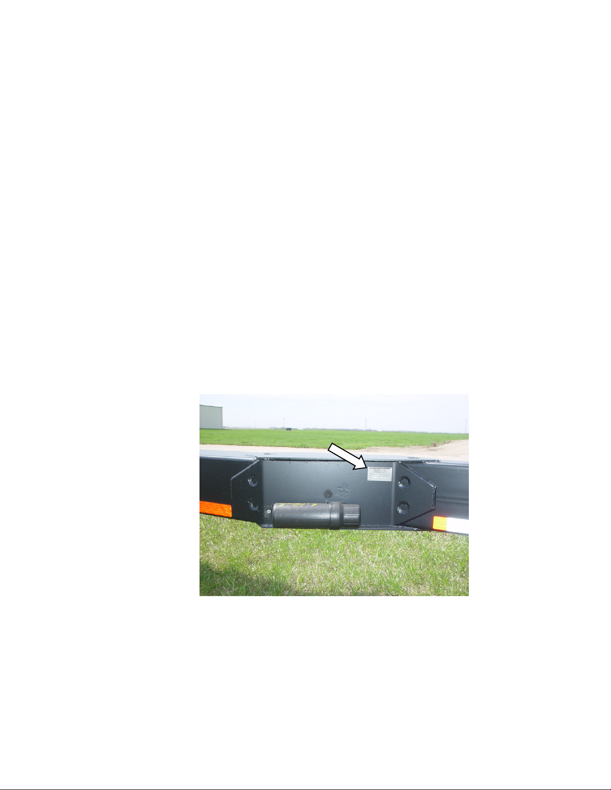
Serial Number plate is located on the right side of the main beam near the front of the Transporter.
Form 169365 Issue – May 2008
Page 2

Page 3

TABLE OF CONTENTS
SECTION G ................................................GENERAL INFORMATION
SECTION UA ................................................. SETUP INSTRUCTIONS
SECTION OM .................................................OPERATOR’S MANUAL
Form 169365 Issue – May 2008
Page 4

Page 5

SECTION G – GENERAL INFORMATION
SECTION G – GENERAL INFORMATION
Section Contents
ITEM DESCRIPTION PAGE G-
1
SAFETY .........................................................................................................................................................1
1.1 SAFETY ALERT SYMBOL ......................................................................................................................1
1.2 SIGNAL WORDS .....................................................................................................................................1
1.3 SAFETY INSTRUCTIONS .......................................................................................................................2
2 RECOMMENDED TORQUES.......................................................................................................................5
2.1 GENERAL ................................................................................................................................................5
2.2 SAE BOLTS .............................................................................................................................................5
2.3 METRIC BOLTS.......................................................................................................................................5
3 ENGLISH/METRIC EQUIVALENTS..............................................................................................................6
Form 169365 Issue – May 2008
Page 6

Page 7

SECTION G – GENERAL INFORMATION
1 SAFETY
1.1 SAFETY ALERT SYMBOL
This safety alert symbol indicates important
safety messages in this manual and on safety
signs on the machine.
This symbol means:
ATTENTION!
BECOME ALERT!
YOUR SAFETY IS INVOLVED!
Carefully read and follow the safety message
accompanying this symbol.
1.2 SIGNAL WORDS
Note the use of the signal words DANGER,
WARNING, and CAUTION with safety
messages. The appropriate signal word for each
message has been selected using the following
guidelines:
DANGER
Indicates an imminently hazardous
situation that, if not avoided, will result in
death or serious injury.
WARNING
Indicates a potentially hazardous situation
that, if not avoided, could result in death or
serious injury. It is also used to alert
against unsafe practices.
CAUTION
Indicates a potentially hazardous situation
that, if not avoided, may result in minor or
moderate injury. It is also used as a
reminder of good safety practices.
WHY IS SAFETY IMPORTANT TO YOU?
ACCIDENTS DISABLE AND KILL
ACCIDENTS COST
ACCIDENTS CAN BE AVOIDED
1.3 SAFETY SIGNS
• Keep safety signs clean and legible at all
times.
• Replace safety signs that are missing or
become illegible.
• If original parts on which a safety sign was
installed are replaced, be sure the repair
part also bears the current safety sign.
• Safety signs are available from your Dealer
Parts Department.
1.3.1 Safety Sign Installation
a. Be sure the installation area is clean and dry.
b. Decide on the exact location before you remove
the decal backing paper.
c. Remove the smaller portion of the split backing
paper.
d. Place the sign in position and slowly peel back
the remaining paper, smoothing the sign as it is
applied.
e. Small air pockets can be smoothed out or
pricked with a pin.
Form 169365 G-1 Issue– May 2008
Page 8
SECTION G – GENERAL INFORMATION
1.3.2 Safety Sign Locations
#188405
Form 169365 G-2 Issue– May 2008
Page 9

SECTION G – GENERAL INFORMATION
1.4 SAFETY INSTRUCTIONS
CAUTION
The following are general farm safety
precautions that should be part of your
operating procedure for all types of
machinery.
Protect yourself.
• Provide a first-aid kit for use in case of
emergencies.
• Keep young children away from machinery at
all times.
• Be aware that accidents often happen when
the operator is tired or in a hurry to get
finished. Take the time to consider the safest
way. Never ignore warning signs of fatigue.
• Wear close-fitting clothing and cover long
hair. Never wear dangling items such as
scarves or bracelets.
• Keep hands, feet, clothing and hair away
from moving parts. Never attempt to clear
obstructions or objects from a machine while
the engine is running.
• Keep all shields in place. Never alter or
remove safety equipment. Make sure
driveline guards can rotate independently of
the shaft and can telescope freely.
• When assembling, operating and servicing
machinery, wear all the protective clothing
and personal safety devices that COULD be
necessary for the job at hand. Don't take
chances.
• You may need:
o a hard hat.
o protective shoes with slip resistant soles.
o protective glasses or goggles.
o heavy gloves.
o wet weather gear.
o respirator or filter mask.
o hearing protection. Be aware that
prolonged exposure to loud noise can
cause impairment or loss of hearing.
Wearing a suitable hearing protective
device such as ear muffs (A) or ear plugs
(B) protects against objectionable or loud
noises.
• Use only service and repair parts made or
approved by the equipment manufacturer.
Substituted parts may not meet strength,
design, or safety requirements.
• Replace any caution, warning, danger, or
instructional safety decal that is unreadable
or is missing. See paragraph for location of
decals.
• Do not modify the machine. Unauthorized
modifications may impair the function and/or
safety and affect machine life.
• Do not allow persons to operate or assemble
this unit until they have developed a
thorough understanding of safety
precautions and how it works.
(continued next page)
A
Form 169365 G-3 Issue– May 2008
B
Page 10

SECTION G – GENERAL INFORMATION
• Stop engine and remove key from ignition
before leaving operator's seat for any
reason. A child or even a pet could engage
an idling machine.
• Keep the area used for servicing machinery
clean and dry. Wet
or oily floors are
slippery. Wet spots
can be dangerous
when working with
electrical
equipment. Be
sure all electrical
outlets and tools
are properly
grounded.
• Use adequate light
for the job at hand.
• Keep machinery clean. Do not allow oil or
grease to accumulate on service platforms,
ladders or controls. Clean machines before
storage.
• Never use gasoline, naphtha or any volatile
material for cleaning purposes. These
materials may be toxic and/or flammable.
• When storing machinery, cover sharp or
extending components to prevent injury from
accidental contact.
Form 169365 G-4 Issue– May 2008
Page 11
SECTION G – GENERAL INFORMATION
2 RECOMMENDED TORQUES
2.1 GENERAL
The tables shown below give correct torque
values for various bolts and capscrews.
• Tighten all bolts to the torques specified in
chart unless otherwise noted throughout this
manual.
• Check tightness of bolts periodically, using
bolt torque chart as a guide.
• Replace hardware with the same strength
bolt.
• Torque figures are valid for non-greased or
non-oiled threads and heads unless
otherwise specified. Do not grease or oil
bolts or capscrews unless specified in this
manual. When using locking elements,
increase torque values by 5%.
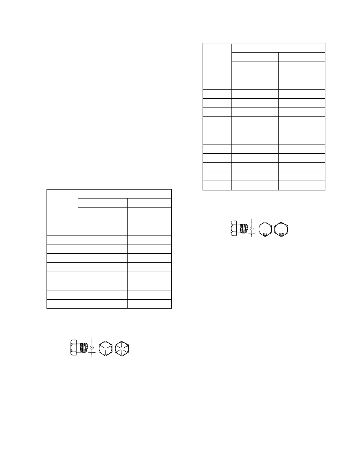
2.2 SAE BOLTS
NC BOLT TORQUE *
BOLT
DIA. "A"
1/4" 9 12 11 15
5/16" 18 24 25
3/8" 32 43 41
7/16" 50 68 70 95
1/2" 75 102 105 142
9/16" 110 149 149 202
5/8" 150 203 200 271
3/4" 265 359 365 495
7/8" 420 569 600 813
1" 640 867 890 1205
* Torque categories for bolts and capscrews are identified by
their head markings.
SAE 5 SAE 8
lbf-ft N·m lbf-ft N·m
34
56
2.3 METRIC BOLTS
NC BOLT TORQUE *
BOLT
DIA. "A"
M3 0.4 0.5 1.3 1.8
M4 2.2 3 3.3 4.5
M5 4 6 7 9
M6 7 10 11 15
M8 18 25 26 35
M10 37 50 52 70
M12 66 90 92 125
M14 103 140 148 200
M16 166 225 229 310
M20 321 435 450 610
M24 553 750 774 1050
M30 1103 1495 1550 2100
M36 1917 2600 2710 3675
* Torque categories for bolts and capscrews are identified by
their head markings.
8.8 10.9
lbf-ft N·m lbf-ft N·m
10.9
8.8
SAE-8
SAE-5
Form 169365 G-5 Issue– May 2008
Page 12

SECTION G – GENERAL INFORMATION
3 ENGLISH/METRIC
EQUIVALENTS
ENGLISH FACTOR SI UNITS (METRIC)
acres x 0.4047 = hectares (ha)
ft/min x 0.3048 = meters/min (m/min)
ft/s x 0.3048 = meters/sec (m/s)
gal
(US)
US
gal/min
(gpm)
hp x 0.7457 = kilowatts (kW)
in.3 x 16.3871
lbf x 4.4482 = Newtons (N)
lbf-ft or
ft-lb
lbf-in.
or in-lbf
mph x 1.6063 = kilometers/hour (km/h)
oz. x 29.5735 = milliliters (ml)
pint
(US)
psi x 6.8948 = kilopascals (kPa)
psi x 0.00689 = megapascals (MPa).
qt. (US) x 0.9464 = liters (L)
x 3.7854 = liters (L)
x 3.7854 = liters/min (L/min)
= cubic centimeters (cm
or cc)
x 1.3558 = Newton meters (N·m)
x 0.1129 = Newton meters (N·m)
x 0.4732 = liters (L)
3
Form 169365 G-6 Issue– May 2008
Page 13

SECTION UA – UNLOADING AND SETUP
Section Contents
ITEM DESCRIPTION PAGE UA-
STEP 1.
STEP 2. CONFIGURE THE TRANSPORTER ..............................................................................................2
STEP 3. SET UP COMBINE HITCH – THREE-AXLE ONLY ........................................................................8
STEP 4. PRE-DELIVERY CHECK ................................................................................................................9
STEP 5. LUBRICATE THE TRANSPORTER................................................................................................9
UNLOAD TRANSPORTER .............................................................................................................1
A. ONE-AXLE..................................................................................................................................2
B. TWO-AXLE .................................................................................................................................3
C. THREE-AXLE..............................................................................................................................4
D. TRANSPORTER ADJUSTMENT PROCEDURES.....................................................................5
I. CUTTERBAR SUPPORTS ....................................................................................................5
II. MOVING REAR AXLES.........................................................................................................5
III. ADJUSTING AXLE SPACING – TWO & THREE AXLE........................................................6
IV. BUMPER................................................................................................................................7
V. FRONT AND REAR SUPPORTS – TWO & THREE AXLE...................................................7
A. TIRE PRESSURE .......................................................................................................................9
B. WHEEL BOLT TORQUE ............................................................................................................9
C. LIGHTS.......................................................................................................................................9
D. BRAKES......................................................................................................................................9
E. BREAKAWAY SWITCH ..............................................................................................................9
F. MANUALS...................................................................................................................................9
Form 169365 Issue– May 2008
Page 14

Page 15
SECTION UA – UNLOADING AND SETUP
STEP 1. UNLOAD TRANSPORTER
CAUTION
To avoid injury to bystanders from being
struck by machinery, do not allow persons
to stand in unloading area.
CAUTION
Equipment used for unloading must meet
or exceed the requirements specified
below. Using inadequate equipment may
result in vehicle tipping or machine
damage.
g. Check for shipping damage and missing parts.
LIFTING VEHICLE
Min. Lifting
Capacity *
Min. Fork Length
* At 48 inches (1220 mm) from back end of
forks.
IMPORTANT
Forklifts are normally rated for a load
located 24 inches (610 mm) ahead of
back end of the forks. To obtain the
forklift capacity at 48 inches (1220 mm),
check with your forklift distributor.
5000 lb. (2270 kg)
60 inches (1524 mm)
CAUTION
Never use the axle or any portion of the
suspension to lift or support the
transporter. This will damage the axle and
lead to premature failure.
a. Remove hauler's tie down straps and chains.
b. Attach sling(s) to transporter. Locate slings on
transporter to ensure it is lifted evenly.
CAUTION
If transporter is not supported properly, it
will have a tendency to rotate as it is lifted,
and may cause serious injury, or damage
adjacent equipment.
c. Approach transporter with forklift or equivalent
from either side of hauling equipment. Attach
slings to lifting device with chains.
d. Lift transporter off trailer bed and back up until
unit clears trailer. Slowly lower to 6 inches (150
mm) from ground.
e. Take to storage or set-up area.
f. Set transporter down securely on level ground.
Form 169365 UA-1 Issue – May 2008
Page 16
SECTION UA – UNLOADING AND SETUP
”
STEP 2. CONFIGURE THE
TRANSPORTER
The transporter must be set up to carry a
specific size and type of header. Refer to
applicable section for each model of transporter.
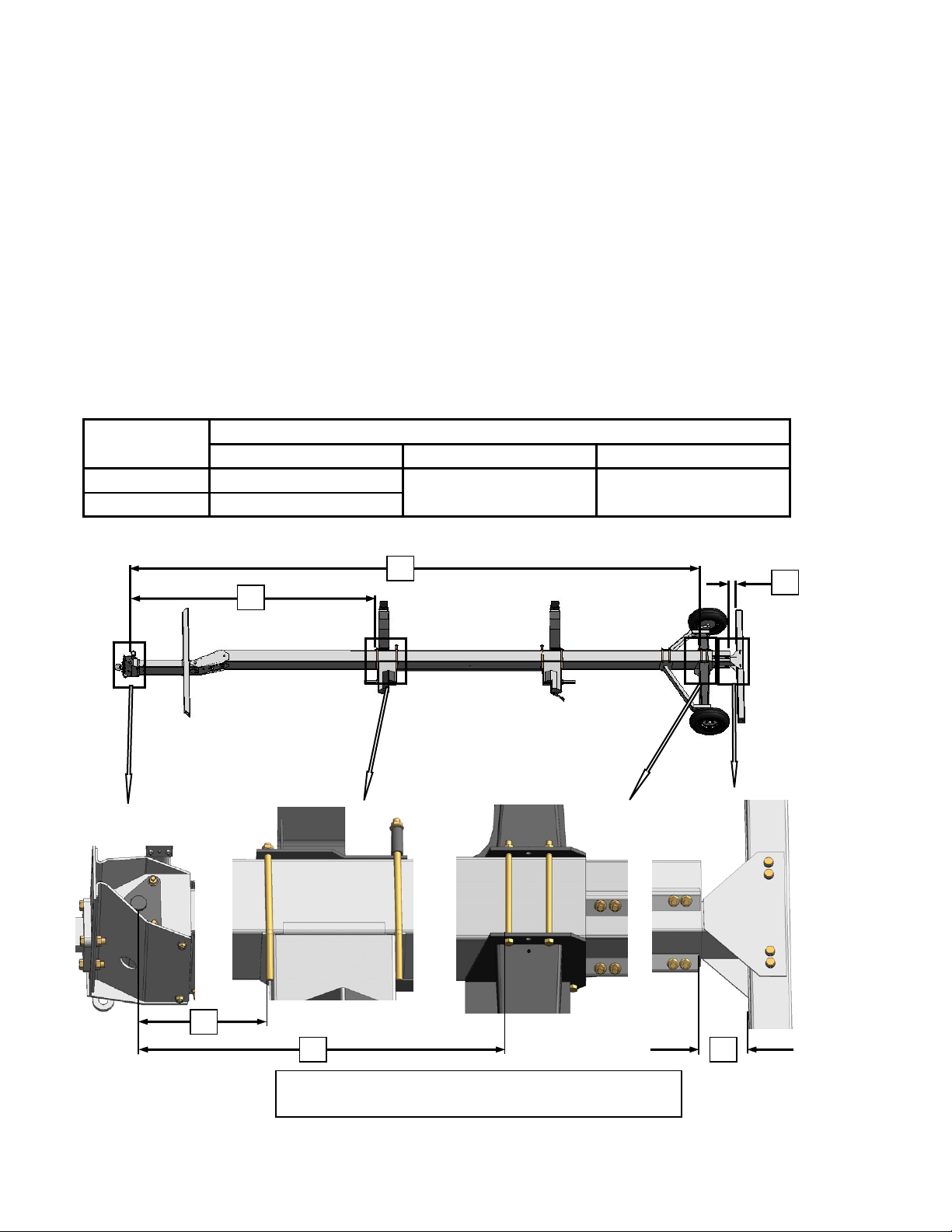
A. ONE-AXLE
The one-axle transporter is designed to carry D Series 25 ft, and 30 ft windrower headers using a truck or an
M Series windrower tractor. Determine the header that the transporter will carry and set up the transporter in
accordance with the following table: Refer to paragraph D, TRANSPORTER ADJUSTMENT PROCEDURES
for instructions.
IMPORTANT
The one-axle transporter is not designed to carry a 30 ft combine header. Do not exceed 5400 lb
(2452 kg) header weight. Ensure attachments and header weight conform.
D SERIES
HEADER SIZE
25’
30’
A B C
181.8 (4618)
162.1 (4118)
A
DIMENSION inches (mm)
423.1 (10747) 4.84 (123)
B
C
A
B C
NOTE
Dimensions “A” and “B
Form 169365 UA-2 Issue – May 2008
are to forward edge of bolts.
Page 17
SECTION UA – UNLOADING AND SETUP
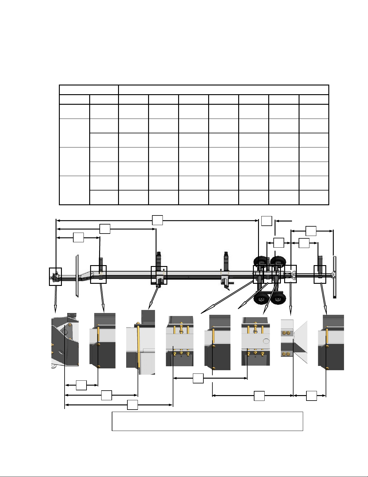
B. TWO-AXLE
The two-axle transporter is designed to carry D Series and FD Series 25 ft, 30 ft, 35 ft, and 40 ft windrower
and combine headers using a truck or an M Series windrower tractor. Determine the header that the
transporter will carry and set up the transporter in accordance with the following table. Refer to paragraph D,
TRANSPORTER ADJUSTMENT PROCEDURES for instructions.
HEADER DIMENSION inches (mm)
SIZE
25’ D
30’
35’
40’
MODEL A B C D E F G
D
FD
D
FD
D
FD
No
Support
No
Support
92.0
(2338)
86.7
(2202)
78.4
(1922)
82.8
(2102)
78.8
(2002)
226.9
(5763)
203.1
(5160)
189.2
(4806)
228.7
(5808)
203.3
(5163)
229.3
(5823)
229.8
(5836)
393.4
(9992 0
393.4
(9992)
393.4
(9992 0
385.5
(9792)
367.8
(9343)
393.4
(9992 0
378.3
(9610)
31.5
(800)
31.5
(800)
31.5
(800)
39.4
(1000)
39.4
(1000)
31.5
(800)
31.5
(800)
No
Support
No
Support
No
Support
30.2
(768)
9.33
(237)
40.8
(1037)
60.5
(1537)
5.67
(144)
15.0
(380)
6.6
(168)
56.9
(1445)
43.9
(1114)
100.0
(2540)
100.4
(2549)
No
Support
No
Support
38.4
(976)
No
Support
No
Support
No
Support
No
Support
A
A
B
B
C
C
D
F
G
E
D
G
E
NOTE
Dimensions “A”, “B”, “C”, “D”, “E”, & “H” are to forward edge of bolts.
Form 169365 UA-3 Issue – May 2008
Page 18
SECTION UA – UNLOADING AND SETUP
,
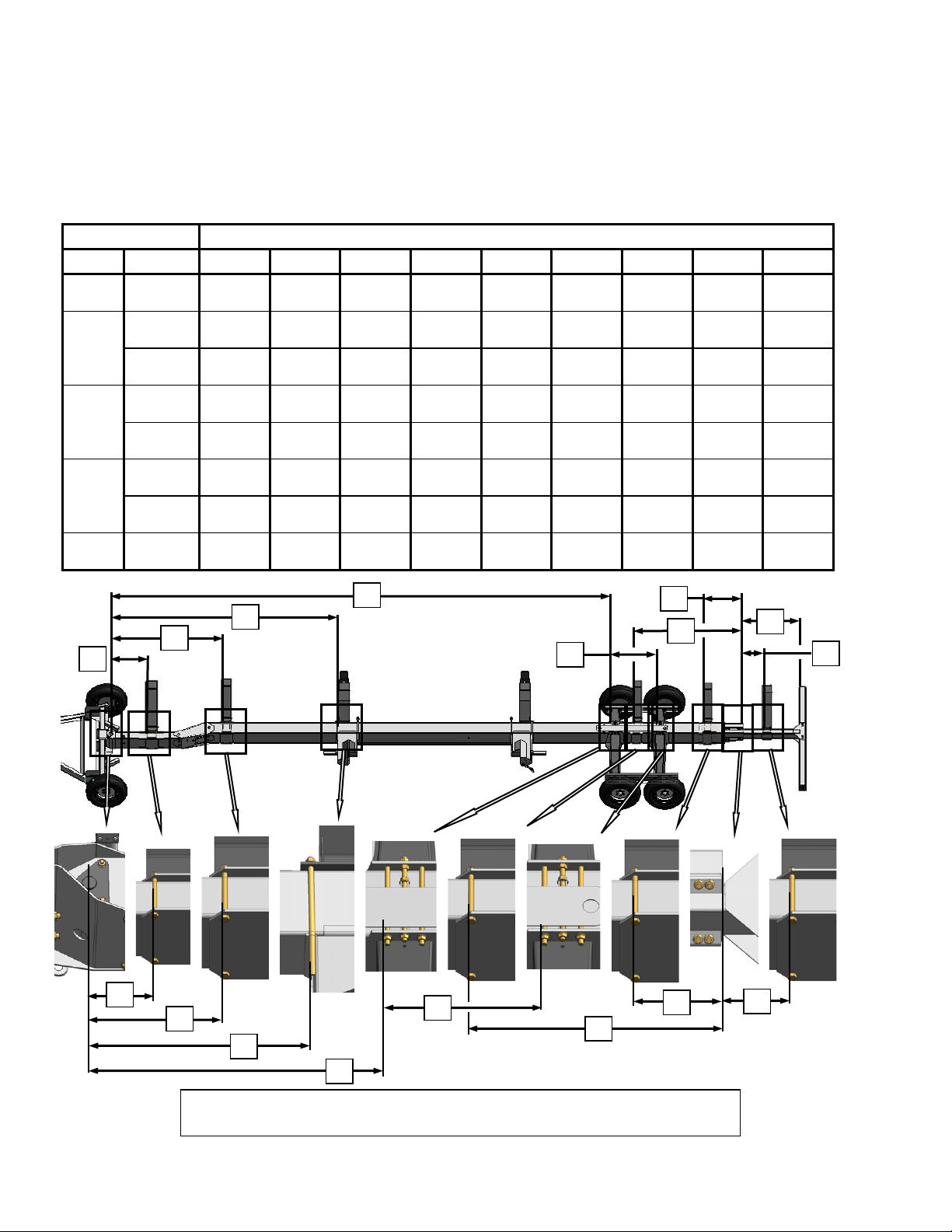
C. THREE-AXLE
The three-axle transporter is designed to carry D Series and FD Series 25 ft, 30 ft, 35 ft, 40 ft, and 45 ft
windrower and combine headers using either a truck, a M Series windrower tractor, or a combine. Determine
the header that the transporter will carry and set up the transporter in accordance with the following table.
Refer to paragraph D, TRANSPORTER ADJUSTMENT PROCEDURES, for adjustment instructions.
HEADER DIMENSION inches (mm)
SIZE MODEL A B C D E F G H J
25’ D
30’
35’
40’
45’
A
D
FD
D
FD
D
FD
D
B
No
Support
No
Support
No
Support
19.5
(495)
19.5
(495)
19.5
(495)
19.5
(495)
19.5
(495)
C
No
Support
No
Support
2402
No
Support
No
Support
No
Support
No
Support
No
Support
191.5
(4863)
187.5
(4763)
189.2
(4805)
140.3
(3563)
138.3
(3513)
167.8
(4263)
167.8
(4263)
191.5
(4852)
D
385.5
(9792)
382.1
(9705)
393.4
(9992)
297.1
(7547)
302.9
(7693)
341.3
(8670)
318.1
(8080)
385.5
(9792)
No
Support
No
Support
No
Support
47.1
(1197)
49.1
(1247)
No
Support
No
Support
No
Support
31.5
(800)
31.5
(800)
31.5
(800)
39.4
(1000)
39.4
(1000)
31.5
(800)
31.5
(800)
31.5
(800)
F
No
Support
No
Support
943
No
Support
No
Support
No
Support
No
Support
No
Support
E
G
5.2
(133)
5.2
(133)
5.2
(133)
5.2
(133)
5.2
(133)
37.8
(960)
37.8
(960)
91.4
(2322)
No
Support
No
Support
No
Support
No
Support
No
Support
1.9 (48)
1.9 (48)
63.1
(1602)
H
J
A
B
F
E
G
J
C
D
NOTE
Dimensions “A”
Form 169365 UA-4 Issue – May 2008
“B”, “C”, “D”, “E”, “F”, “G”, & “J” are to forward edge of bolts.
Page 19
SECTION UA – UNLOADING AND SETUP
D. TRANSPORTER ADJUSTMENT
PROCEDURES
I. CUTTERBAR SUPPORTS
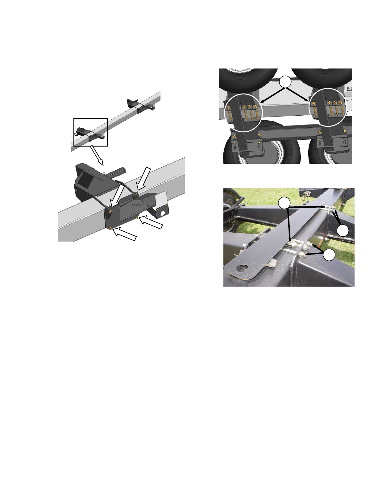
II. MOVING REAR AXLES
Two & Three Axle Transporter Only
A
a. Loosen four lower bolts (A) on each axle
support.
C
B
a. Loosen four nuts on each support.
b. Slide both supports to specified location (see
previous page).
NOTE
Supports are joined by a tie angle and
move together to maintain correct
spacing.
c. Re-tighten nuts. Ensure supports are evenly
clamped onto main beam.
B
b. Loosen two bolts (B) on each axle support
topside.
c. Loosen outer nuts on both adjuster rods (C).
d. Turn inner nuts on both adjuster rods (C) so that
left and right frames separate approximately 3
mm from main beam.
e. Slide tandem axle assembly to desired location.
Holes are provided on adjuster plate for
attaching a winch or come-along.
NOTE
Ensure winch pulls adjuster plate straight
to avoid binding.
f. Tighten inner nuts on adjuster rods (C) against
adjuster plate.
g. Retighten all nuts and bolts. Ensure supports
are evenly clamped onto main beam.
Form 169365 UA-5 Issue – May 2008
Page 20
SECTION UA – UNLOADING AND SETUP
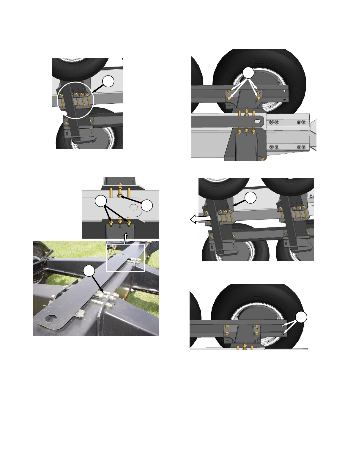
III. ADJUSTING AXLE SPACING – TWO &
THREE AXLE
D
a. Loosen four bolts (D) on underside of axle to be
moved.
f. Remove the four bolts (H) on both sides of rear
H
axle mount (J).
E
G
b. Loosen two bolts (E) on topside of forward axle.
c. Loosen outer nuts on the forward axle adjuster
rod (F).
d. Turn inner nuts on adjuster rod (F) so that left
and right frames separate slightly from main
beam.
e. Remove adjuster rod (G) on rear axle.
F
J
g. Slide axle to new location and line up rear axle
mounting holes (K).
K
h. Re-install four bolts removed at step e. on both
sides of rear axle mount and tighten.
i. Re-install adjuster rod (G) in adjuster plate and
tighten.
j. Tighten all remaining nuts.
Form 169365 UA-6 Issue – May 2008
Page 21

SECTION UA – UNLOADING AND SETUP
IV. BUMPER
A
a. Loosen eight nuts (A) on bumper clamps.
b. Slide bumper (B) to specified location (see
previous page).
c. Re-tighten nuts. Ensure nuts are evenly
tightened.
B
V. FRONT AND REAR SUPPORTS – TWO &
THREE AXLE
D
C
FRONT SUPPORT SHOWN – REAR SUPPORT SIMILAR
a. Loosen four bolts (C) on support (D).
b. Slide support to desired location and retighten
bolts. Ensure supports are evenly clamped onto
main beam.
Form 169365 UA-7 Issue – May 2008
Page 22

SECTION UA – UNLOADING AND SETUP
STEP 3. SET UP COMBINE HITCH
– THREE-AXLE ONLY
The combine hitch can be configured in two
lengths depending on the combine and header
size. The longer hitch is for combines where
there is insufficient clearance between the rear
of the combine and the header reel when
rounding corners.
CAUTION
Towing the transporter with a truck when
the combine hitch is installed is not
recommended for highway travel. If
necessary, a pintle type hitch should be
installed on the truck and the transporter
combine hitch (p/n 113566) in place of the
clevis type hitch.
a. Detach tow-bar from storage position on
transporter.
A
E
e. Install receptacle bracket (E) onto lugs on hitch
with hardware provided.
f. Attach wiring receptacle to bracket with
hardware provided.
G
C
D
B
b. Ensure stop-bolt (A) is installed.
c. Position combine tow-bar (B) inside channel (C)
under existing hitch in either long or short
location. Illustration shows long setup.
d. Install two bolts and castle nuts (D) to secure
combine hitch to channel. Secure castle nuts
with cotter pins.
D
g. Secure wiring to lugs on hitch with clamps and
hardware provided at four locations (G).
h. Connect plug from transporter to receptacle on
combine hitch.
Form 169365 UA-8 Issue – May 2008
Page 23

SECTION UA – UNLOADING AND SETUP
STEP 4. PRE-DELIVERY CHECK
Perform the final checks and adjustments as
listed on the "Pre-Delivery Checklist" (yellow
sheet attached to back of this instruction) to
ensure the machine is field-ready. Refer to the
pages for detailed instructions as indicated on
the checklist.
The completed checklist should be retained
either by the operator or the dealer.
A. TIRE PRESSURE
a. Check tire pressure on all tires. Correct
pressure is 65 psi (448 kPa).
B. WHEEL BOLT TORQUE
1
6
b. Drive slowly forward and apply brakes. Observe
if electric brakes on transporter are operational.
c. There should be no sensation of the transporter
pushing or pulling the tow vehicle.
D. LIGHTS
a. Check function of running lights, signal lights,
hazard lights, and brake lights.
E. BREAKAWAY SWITCH
4
2
a. Check wheel bolt torque on all wheels. Correct
torque is 90-120 ft-lbf (122-163 N·m).
3
5
C. BRAKES
a. Hitch transporter to towing vehicle and connect
transporter wiring harness to towing vehicle.
FRONT VIEW – COVER OPEN
IMPORTANT
Center pin on towing vehicle electrical
receptacle must not be energized,
otherwise the transporter brakes will be
activated. Re-wire receptacle if
necessary.
a. Check breakaway switch operation by firmly
pulling on pin in breakaway switch. The brakes
should activate when the pin is pulled.
F. MANUALS
a. The owner’s manual storage case is located
near the front of the transporter on the right side.
b. Check that it is mounted securely.
c. Store this manual and other applicable
documents in storage case.
STEP 5. LUBRICATE THE
TRANSPORTER
Refer to SECTION OM, Paragraph 4.2,
Lubricating the Transporter
Form 169365 UA-9 Issue – May 2008
Page 24

Page 25

SECTION OM – OPERATOR’S INSTRUCTIONS
Section Contents
ITEM DESCRIPTION PAGE OM-
1
COMPONENT IDENTIFICATION..................................................................................................................3
2 SPECIFICATIONS AND WEIGHT DATA ......................................................................................................4
2.1 SPECIFICATIONS ...................................................................................................................................4
2.2 TRANSPORTER WEIGHT AND TONGUE WEIGHT DATA ...................................................................5
3 OPERATION..................................................................................................................................................6
3.1 OWNER/OPERATOR RESPONSIBILITIES............................................................................................6
3.2 OPERATIONAL SAFETY.........................................................................................................................6
3.3 FIRST USE ..............................................................................................................................................6
3.4 TOWING ONE-AXLE AND TWO-AXLE TRANSPORTERS WITH M SERIES WINDROWER
TRACTOR .........................................................................................................................................................7
3.4.1 Attaching Adapter Hitch to Windrower Tractor ...........................................................................7
3.4.2 Hookup to Windrower Adapter Hitch...........................................................................................8
3.4.3 Unhook From Windrower Adapter Hitch .....................................................................................9
3.4.4 Unhook From Windrower Leaving Adapter Hitch on Transporter...............................................9
3.5 TOWING ONE-AXLE AND TWO-AXLE TRANSPORTERS WITH TRUCK..........................................11
3.5.1 Hookup to Truck........................................................................................................................11
3.5.2 Unhooking from Truck...............................................................................................................12
3.6 TOWING THREE-AXLE TRANSPORTER WITH M SERIES WINDROWER TRACTOR.....................13
3.6.1 Transporter Hookup to Windrower Adapter Hitch.....................................................................13
3.6.2 Unhook From Windrower Leaving Adapter Hitch on Transporter.............................................14
3.6.3 Windrower Hookup to Adapter Hitch on Transporter................................................................15
3.6.4 Transporter Unhook From Windrower Adapter Hitch ...............................................................15
3.7 TOWING THREE-AXLE TRANSPORTER WITH COMBINE ................................................................16
3.7.1 Hookup To Combine .................................................................................................................16
3.7.2 Unhook From Combine.............................................................................................................17
3.8 TOWING THREE-AXLE TRANSPORTER WITH TRUCK.....................................................................18
3.8.1 Hookup to Truck........................................................................................................................18
3.8.2 Unhook from Truck....................................................................................................................18
3.9 LOADING D SERIES WINDROWER HEADER ONTO TRANSPORTER.............................................19
3.9.1 Prepare the Header...................................................................................................................19
3.9.2 Prepare the Transporter............................................................................................................20
3.9.3 Loading Procedure....................................................................................................................20
3.9.4 Engage Cutterbar Tie-downs ....................................................................................................21
3.9.5 Attach Header Anchor Chain ....................................................................................................23
3.10 UNLOADING D SERIES WINDROWER HEADER ...............................................................................24
3.11 LOADING D AND FD SERIES COMBINE HEADER.............................................................................26
3.11.1 Prepare the Header and Transporter........................................................................................26
3.11.2 Loading Procedure....................................................................................................................27
3.12 UNLOADING D AND FD SERIES COMBINE HEADER .......................................................................29
3.13 ATTACHING/DETACHING CA20 COMBINE ADAPTER ......................................................................30
3.14 STORAGE..............................................................................................................................................30
4 MAINTENANCE...........................................................................................................................................31
4.1 RECOMMENDED SAFETY PROCEDURES.........................................................................................31
4.2 LUBRICATING THE TRANSPORTER ..................................................................................................31
4.2.1 Lubricants..................................................................................................................................31
4.2.2 Lubricant Storage......................................................................................................................31
4.2.3 Greasing Requirements ............................................................................................................31
4.3 WHEELS AND TIRES............................................................................................................................32
4.3.1 Wheel Nuts................................................................................................................................32
4.3.2 Wheel - Removal/Installation ....................................................................................................32
4.3.2.1 Removal .................................................................................................................................................. 32
4.3.2.2 Installation ............................................................................................................................................... 33
Form # 169365 Issue – May 2008
Page 26

SECTION OM – OPERATOR’S MANUAL
4.3.3 Tires ..........................................................................................................................................34
4.3.3.1 Inflation ....................................................................................................................................................34
4.3.3.2 Wear ........................................................................................................................................................34
4.4 ELECTRICAL.........................................................................................................................................35
4.4.1 Lights ........................................................................................................................................35
4.4.1.1 Tail/Brake/Signal Replacement................................................................................................................35
4.4.1.2 Clearance Lights ......................................................................................................................................35
4.4.1.3 Red Light Bar ...........................................................................................................................................35
4.4.1.4 License Plate Light...................................................................................................................................35
4.4.2 Electric Brakes ..........................................................................................................................35
4.4.2.1 Wiring.......................................................................................................................................................35
4.4.2.2 Brake Adjustment.....................................................................................................................................35
4.4.2.3 Breakaway Battery...................................................................................................................................36
4.5 MAINTENANCE SCHEDULE................................................................................................................37
5 TROUBLESHOOTING.................................................................................................................................39
Form # 169254 OM-2 Issue – April 2008
Page 27

SECTION OM – OPERATOR’S MANUAL
1 COMPONENT IDENTIFICATION
CUTTERBAR SUPPORT
HEADER LEG SUPPORT
BREAKAWAY SYSTEM BATTERY
MANUAL CASE
CUTTERBAR TIE-DOWN
GUIDE
COMBINE HITCH
TRACTOR/TRUCK HITCH BREAKAWAY SWITCH
CUTTERBAR TIE-DOWN
THREE-AXLE TRANSPORTER
BUMPER
CUTTERBAR SUPPORT
CUTTERBAR TIE-DOWN
HEADER LEG SUPPORT
LIGHTBAR
BREAKAWAY SWITCH
HEIGHT ADJUSTABLE PINTLE HITCH
ONE AND TWO-AXLE TRANSPORTER
Form # 169365 OM-3 Issue – May 2008
Page 28

SECTION OM – OPERATOR’S MANUAL
2 SPECIFICATIONS AND WEIGHT DATA
2.1 SPECIFICATIONS
ITEM
AXLES
MAX GROSS TRANSPORT WEIGHT
LENGTH
WIDTH
TREAD WIDTH
WEIGHT
MINIMUM HITCH LOAD
TIRES
Pressure 65 psi (448 kPa)
MT8-1 MT8-2 MT8-3
One Two Three
8000 lb (3620 kg) 12000 lb (5430 kg) 14000 lb (6335 kg)
467 in. (11866 mm)
2613 lb (1182 kg) 3255 lb (1473 kg) 3755 lb (1699 kg)
2000 lb (905 kg) 3000 lb (1375 kg) <100 lb. (45 kg)
SPECIFICATION
468-563 in.
(11891-14301 mm)
100.75 in. (2560 mm)
88 in. (2235 mm)
ST225/75 R15 LR D
580-617 in.
(14730-15673 mm)
MAX HEADER SIZE
SUSPENSION
ADJUSTABLE CUTTERBAR SUPPORTS
TOWING VEHICLE
TOWING SPEED
BRAKES
FENDERS
30 ft D Series 40 ft D or FD Series 45 ft D or FD Series
Flex Torsion Axle
Two Two Two or Three
Truck, M Series Windrower Tractor
(See Note 2)
Highway
Electric Drum on All Wheels (See Note 4)
Each Wheel
Truck, M Series
Windrower Tractor,
Combine
(See Note 3)
NOTES:
1. Specifications and design are subject to change without notice or obligation to revise previously sold
units.
2. Ensure that truck and truck hitch are rated for maximum gross weight and maximum hitch load.
Hitch loads require a suitably sized truck.
3. Ensure that truck and truck hitch are rated for maximum gross weight.
4. Requires electric brake controller to be installed in truck.
Form # 169365 OM-4 Issue – May 2008
Page 29

SECTION OM – OPERATOR’S MANUAL
2.2 TRANSPORTER WEIGHT AND TONGUE WEIGHT DATA
IMPORTANT: Weights are estimated and owner should check transporter weight when loaded. Weights will
vary significantly depending on header options, (number of reel bats, steel versus plastic fingers etc)
HEADER
SIZE MODEL GROSS TONGUE GROSS TONGUE GROSS TONGUE
25’
D Wind
7995 (3630)
ONE-AXLE TWO-AXLE THREE-AXLE
3179
(1443)
D Comb Do Not Use
30’
D Wind
D Comb
7945
(3607)*
3418
(1552)
FD
D
35’
FD
Do Not Use
D
40’
FD
45’ D
* Do not exceed 5400 lb (2452 kg) header weight. Ensure attachments and header weight conform.
WEIGHT pounds (kilograms)
9764 (4433)
max
9805 (4451)
2718 (1234)
max
3471 (1576)
max
10864
(4932)
11259
3918 (1779)
max
(5112)
10984
(4987)
11421
3661 (1662)
max
(5185)
11489
(5216)
11706
3245 (1473)
max
(5314)
Do Not Use
3743 (1699)
max
11750
(5334) max
11912
(5408) max
12197
(5537) max
12650
(5743)
<500 (227)
Weight
Transfer
Springs Not
Engaged
Form # 169365 OM-5 Issue – May 2008
Page 30

SECTION OM – OPERATOR’S MANUAL
3 OPERATION
3.1 OWNER/OPERATOR
RESPONSIBILITIES
CAUTION
• It is your responsibility to read and
understand this manual completely
before operating the mower
conditioner. Contact your dealer if an
instruction is not clear to you.
• Follow all safety messages in the
manual and on safety signs on the
machine.
• Remember that YOU are the key to
safety. Good safety practices protect
you and the people around you.
• Review the manual and all safety
related items with all operators
annually.
• Be alert for other operators not using
recommended procedures or not
following safety precautions. Correct
these mistakes immediately, before an
accident occurs.
• Do not modify the machine.
Unauthorized modifications may impair
the function and/or safety and affect
machine life.
• The safety information given in this
manual does not replace safety codes,
insurance needs, or laws governing
your area. Be sure your machine meets
the standards set by these regulations.
3.2 OPERATIONAL SAFETY
Follow these safety precautions:
CAUTION
• Follow all safety and operational
instructions given in your towing
vehicle Operator's Manual. If you do
not have a manual, get one from your
dealer and read it thoroughly.
• Never move the unit until you are sure
all bystanders have cleared the area.
• Stop towing vehicle engine and remove
key before adjusting the transporter. A
child or even a pet could engage the
drive.
• Check for excessive vibration and
unusual noises. If there is any
indication of trouble, shut down the
towing vehicle and inspect the
transporter. Follow proper shutdown
procedure:
o engage tractor brake
o disengage PTO
o turn off engine and remove key
• Operate only in daylight or good
artificial light.
• Do not carry passengers on equipment.
• Pick the most level possible route when
towing the transporter across fields.
Avoid edges of ditches, gullies, and
steep hills.
• Be extra careful when working on
inclines.
• Manoeuvre towing vehicle at safe
speeds.
• Avoid loose gravel, rocks, and holes;
they can be dangerous for equipment
operation or movement.
• Allow for transporter length when
turning.
• Ensure towing vehicle is capable of
towing the transporter when empty or
when loaded with a header. Refer to
SECTION OM, Paragraph 2,
Specifications for gross transport
weights.
• To avoid bodily injury and or machine
damage caused by loss of control:
o Reduce transport speed for slippery
or rough conditions.
o Obey all highway traffic regulations
in your area when transporting on
public roads.
3.3 FIRST USE
After attaching transporter to towing vehicle for
the first time, drive slowly, watching and
listening FROM THE OPERATOR'S SEAT for
unusual towing behavior or steering control
problems.
CAUTION
Before investigating an unusual sound or
attempting to correct a problem, shut off
engine, engage parking brake and
remove key.
a. Tighten any loose hardware after the first
5 hours operation. Refer to SECTION G,
Paragraph 2, Recommended Torques.
Form # 169365 OM-6 Issue – May 2008
Page 31

SECTION OM – OPERATOR’S MANUAL
3.4 TOWING ONE-AXLE AND TWOAXLE TRANSPORTERS WITH M
SERIES WINDROWER TRACTOR
The one-axle and two-axle MT8 Header
Transporters can be towed with the MacDon M
Series Windrower Tractor provided that the
MacDon Transporter Adapter Hitch (B5247) is
attached to the tractor.
CAUTION
Towing the Transporter without a header
on the Transporter is not recommended
because of the lack of sufficient weight
on the tractor drive wheels for safe
operation of the tractor.
b. Start tractor and lower windrower lift legs fully
and approach hitch.
c. Line up legs with pockets in hitch and drive
forward until legs fully engage hitch.
CAUTION
If necessary to tow the Transporter
without a header on the Transporter, do
not operate tractor at typical road speed.
Proceed with caution.
3.4.1 Attaching Adapter Hitch to
Windrower Tractor
a. Remove clevis pins from hitch.
d. Rotate stops against legs and insert clevis
pins. Secure with hairpins.
e. Attach safety chain on hitch to center link
mounting bracket on tractor frame. Leave
some slack in chain to allow hitch to be raised
to maximum height of lift linkage. Secure
chain with locking device.
f. Connect wiring harness from hitch to tractor.
Form # 169365 OM-7 Issue – May 2008
Page 32

SECTION OM – OPERATOR’S MANUAL
3.4.2 Hookup to Windrower Adapter Hitch
a. Open pintle on adapter hitch.
b. Start tractor and activate header lift cylinders
on tractor to lower tractor hitch.
c. Slowly approach transporter hitch with tractor
and line up pintle with hitch ring on transporter.
d. Activate header lift cylinders on tractor until
pintle engages hitch ring on transporter. Raise
slightly to take weight of the hitch jack.
e. Stop tractor engine and remove key.
i. Plug in wiring harnesses at tractor hitch and
transporter.
f. Close pintle lock and insert locking pin.
g. Route safety chains through tractor hitch frame
and connect under frame. Ensure hook safety
latches are closed.
h. Turn jack handle to retract jack. Remove pin
from jack and rotate jack to transport position.
Secure jack with pin.
j. Attach breakaway switch lanyard to tractor
adapter hitch.
k. Start tractor and raise header lift legs to full
height (towing mode).
l. Stop tractor engine and remove key.
m. Engage header lift cylinder stops. See tractor
operator’s manual.
n. Remove blocks if used, from transporter
wheels.
Form # 169365 OM-8 Issue – May 2008
Page 33

SECTION OM – OPERATOR’S MANUAL
3.4.3 Unhook From Windrower Adapter
Hitch
a. Stop tractor engine and remove key.
b. Block the transporter wheels to prevent
transporter from moving.
c. Remove pin that holds jack in storage location
on transporter frame. Rotate jack to working
position and re-insert pin to secure jack.
d. Lower jack to the ground. Use a wooden block
if ground is soft.
g. Disconnect breakaway switch lanyard from
windrower hitch.
h. Disconnect electrical plug on windrower hitch.
i. Disengage tractor lift cylinder locks.
j. Start tractor engine and activate header lift
cylinders to lower the hitch and disengage
pintle ring on transporter.
3.4.4 Unhook From Windrower Leaving
Adapter Hitch on Transporter
The following procedure is the normal method
for unhooking the transporter from the
windrower tractor.
e. Remove safety chains from windrower hitch.
f. Remove locking pin from pintle and raise pintle
lock.
a. Stop tractor engine and remove key.
b. Block the transporter wheels to prevent
transporter from moving.
c. Remove pin that holds jack in storage location
on transporter frame. Rotate jack to working
position and re-insert pin to secure jack.
d. Lower jack to the ground. Use a wooden block
if ground is soft.
e. Disengage tractor lift cylinder locks.
f. Start tractor engine and activate header lift
cylinders to lower the adapter hitch onto blocks
or the ground.
(continued next page)
Form # 169365 OM-9 Issue – May 2008
Page 34

SECTION OM – OPERATOR’S MANUAL
g. Stop engine and remove key.
h. Disconnect wiring harness at tractor.
k. Start tractor and back away from hitch.
l. Re-install clevis pins into hitch boots.
i. Remove safety chain from tractor and store on
hitch.
j. Remove clevis pins from tractor legs and set
aside.
Form # 169365 OM-10 Issue – May 2008
Page 35

SECTION OM – OPERATOR’S MANUAL
3.5 TOWING ONE-AXLE AND TWOAXLE TRANSPORTERS WITH
TRUCK
CAUTION
• To avoid bodily injury and/or machine
damage caused by loss of control:
• Check tire condition and pressure prior
to transporting.
• Connect hitch to towing vehicle with a
proper hitch pin with a spring locking
pin or other suitable fastener.
• Attach hitch chain to towing vehicle.
Adjust chain length to remove all slack
except what is needed for turns.
• Ensure wiring is properly connected
and lights and brakes are working
correctly
b. Open pintle and lower transporter hitch onto
truck hitch with jack.
c. Raise jack fully. Remove pin from jack and
rotate to storage location. Secure with pin.
d. Close pintle lock and secure with lynch pin.
CAUTION
Ensure towing vehicle is capable of
handling transporter tongue weight and
gross weight to ensure adequate braking
performance and control.
a. Refer to paragraph 2.2 TRANSPORTER
WEIGHT AND TONGUE WEIGHT DATA for
transporter gross weights and tongue weights.
IMPORTANT
Tongue weight is higher on one and twoaxle transporters than other trailers
because wheels are located to provide
clearances for loading and unloading
procedures.
3.5.1 Hookup to Truck
b. Back up truck to align pintle with transporter
hitch.
a. Shut off truck engine and remove key.
e. Attach safety chains to truck and plug in the
electrical connector to truck receptacle.
FRONT VIEW – COVER OPEN
IMPORTANT
Center pin on towing vehicle electrical
receptacle must not be energized,
otherwise the transporter brakes will be
activated. Re-wire receptacle if
necessary.
(continued next page)
Form # 169365 OM-11 Issue – May 2008
Page 36

SECTION OM – OPERATOR’S MANUAL
f. Check that transporter lights and brakes are
functioning.
g. Attach breakaway lanyard to truck hitch.
3.5.2 Unhooking from Truck
a. Park transporter on level ground.
b. Shutoff truck engine and remove key.
c. Block the transporter wheels.
d. Disconnect electrical plug from truck and store
on transporter.
e. Remove safety chains and breakaway switch
lanyard from truck and store on transporter.
f. Remove lynch pin from pintle and open pintle.
g. Remove pin securing jack in storage position
and rotate jack to working position. Secure
with pin. Place wooden block under jack if
ground is soft.
h. Lower jack to raise transporter hitch ring clear
of truck pintle.
i. Drive truck away from transporter.
Form # 169365 OM-12 Issue – May 2008
Page 37

SECTION OM – OPERATOR’S MANUAL
3.6 TOWING THREE-AXLE
TRANSPORTER WITH M SERIES
WINDROWER TRACTOR
3.6.1 Transporter Hookup to Windrower
Adapter Hitch
CAUTION
Significant weight transfer to tractor is
required for steering and braking in
transport. See tractor operators manual.
d. Slowly approach transporter hitch with tractor
and line up pintle with hitch ring on transporter.
e. Stop tractor engine and remove key.
f. Lift transporter hitch onto tractor pintle hitch.
g. Close pintle lock and insert locking pin.
h. Route safety chains through tractor hitch frame
and connect under frame. Ensure hook safety
latches are closed.
a. Open pintle on tractor hitch.
b. Remove two pins and washers on weight
transfer spring assembly and store in holes in
frame.
c. Start tractor and activate header lift cylinders
to lower tractor hitch to ground.
i. Attach breakaway switch lanyard to tractor
hitch.
j. Retrieve electrical plug from transporter and
connect to receptacle on tractor hitch.
CAUTION
If necessary to tow the Transporter
without a header on the Transporter, do
not operate tractor at typical road speed.
Proceed with caution.
(continued next page)
Form # 169365 OM-13 Issue – May 2008
Page 38

SECTION OM – OPERATOR’S MANUAL
IMPORTANT
If transporter is being moved without a
header on it, do not re-install pins in
weight transfer assembly. Store pins in
holes in frame.
k. If header is on transporter, re-insert pins and
washers in slotted holes weight transfer
assembly.
l. Start tractor and raise header lift legs to full
height (towing mode).
m. Stop tractor engine and remove key.
n. Engage header lift cylinder stops. See tractor
operator’s manual.
o. Remove blocks if used, from transporter
wheels.
f. Disconnect wiring harness at tractor.
g. Remove safety chain from tractor and store on
hitch.
3.6.2 Unhook From Windrower Leaving
Adapter Hitch on Transporter
The following procedure is the normal method
for unhooking the transporter from the
windrower tractor.
a. Stop tractor engine and remove key.
b. Block the transporter wheels to prevent
transporter from moving.
c. Disengage header lift cylinder stops.
d. Start tractor and activate header lift cylinders
to lower hitch to ground.
e. Stop engine and remove key.
h. Remove clevis pins from tractor legs and set
aside.
i. Start tractor and back away from hitch.
j. Re-install clevis pins into hitch boots.
Form # 169365 OM-14 Issue – May 2008
Page 39

SECTION OM – OPERATOR’S MANUAL
3.6.3 Windrower Hookup to Adapter Hitch
on Transporter
Refer to paragraph 3.4.1 Attaching Adapter
Hitch to Windrower Tractor.
3.6.4 Transporter Unhook From
Windrower Adapter Hitch
a. Stop tractor engine and remove key.
b. Block the transporter wheels to prevent
transporter from moving.
c. Disengage header lift cylinder stops.
d. Start tractor and activate header lift cylinders
to lower hitch to ground.
h. Remove safety chains from adapter hitch and
store on transporter hitch.
e. Remove two pins and washers on weight
transfer spring assembly and store in holes in
frame.
i. Lift transporter hitch off tractor adapter pintle
hitch.
f. Disconnect breakaway switch lanyard from
adapter hitch and store on transporter.
g. Disconnect electrical plug on adapter hitch.
Form # 169365 OM-15 Issue – May 2008
Page 40

SECTION OM – OPERATOR’S MANUAL
3.7 TOWING THREE-AXLE
TRANSPORTER WITH COMBINE
Only a three-axle transporter can be towed
with a combine when equipped with the
combine towing hitch assembly.
3.7.1 Hookup to Combine
a. If combine hitch not already installed, refer to
SECTION UA. UNLOADING AND SETUP,
Step 3. Set Up Combine Hitch.
IMPORTANT
Ensure hitch allows sufficient clearance
between combine and header reel.
Adjust hitch if required. Refer to
SECTION UA, Step 3. Set Up Combine
Hitch.
b. Extend the tongue as follows to assist in
hitching to the combine.
4. Lower latch so that forward pin rests on
tongue.
c. Start combine and slowly back up so that
tongue slides back into the tow-bar.
d. Continue to back up until latch re-engages the
tongue.
e. Stop combine engine and remove key.
1. Remove pin in tow-bar latch.
2. Lift latch to disengage tongue.
3. Pull tongue to align with combine hitch
and connect to combine. Refer to
combine Operator’s Manual for
instructions on towing equipment with
the combine.
f. Re-install pin in latch to lock tongue.
g. Attach safety chains to combine.
h. Connect transporter electrical plug to combine
receptacle.
(continued next page)
Form # 169365 OM-16 Issue – May 2008
Page 41

SECTION OM – OPERATOR’S MANUAL
NOTE
Receptacle on combine must be a seven
circuit RV type connector.
FRONT VIEW – COVER OPEN
IMPORTANT
Center pin must not be energized.
i. Attach breakaway switch lanyard to combine.
j. Remove blocks from transporter wheels if
applicable.
3.7.2 Unhook From Combine
a. Park transporter on level ground.
b. Shutoff combine engine and remove key.
c. Block the transporter wheels.
d. Disconnect breakaway switch lanyard from
combine.
e. Disconnect electrical plug from combine and
store on transporter.
f. Remove safety chains and breakaway switch
lanyard from combine and store on transporter.
g. Disconnect transporter hitch from combine.
h. Drive combine away from transporter.
Form # 169365 OM-17 Issue – May 2008
Page 42

SECTION OM – OPERATOR’S MANUAL
3.8 TOWING THREE-AXLE
TRANSPORTER WITH TRUCK
CAUTION
Ensure towing vehicle is capable of
handling transporter tongue weight and
gross weight to ensure adequate braking
performance and control.
3.8.1 Hookup to Truck
a. Refer to paragraph 2.1 TRANSPORTER
WEIGHT AND TONGUE WEIGHT DATA for
transporter gross weights and tongue weights.
b. Back up truck to align pintle with transporter
hitch.
c. Shut off truck engine and remove key.
IMPORTANT
Center pin on towing vehicle electrical
receptacle must not be energized,
otherwise the transporter brakes will be
activated. Re-wire receptacle if
necessary.
g. Check that transporter lights and brakes are
functioning.
h. Attach breakaway lanyard to truck hitch.
d. Open pintle and lift transporter hitch onto truck
hitch.
e. Close pintle lock and secure with lynch pin.
f. Attach safety chains to truck and plug in the
electrical connector to truck receptacle.
3.8.2 Unhook from Truck
a. Park transporter on level ground.
b. Shutoff truck engine and remove key.
c. Block the transporter wheels.
d. Disconnect electrical plug from truck and store
on transporter.
e. Remove safety chains and breakaway switch
lanyard from truck and store on transporter.
f. Remove lynch pin from pintle and open pintle.
g. Lift transporter hitch off truck hitch.
h. Drive truck away from transporter.
Form # 169365 OM-18 Issue – May 2008
Page 43

SECTION OM – OPERATOR’S MANUAL
3.9 LOADING D SERIES WINDROWER
HEADER ONTO TRANSPORTER
a. Set up transporter to suit your header. Refer
to Step 2. Configuring The Transporter in
SECTION UA. UNLOADING AND SETUP.
b. Block the transporter wheels.
3.9.1 Prepare the Header
a. Raise the stabilizer wheels on header as
follows:
C
B
A
D
1. Support wheel weight by lifting slightly
with one hand on handle (A), and pull up
on handle (B) to release lock.
2. Lift wheel with handle (A) to uppermost
position and engage support channel
into slot (C) in upper support.
3. Push down on handle (B) to lock.
b. The right hand stabilizer wheel on 35 ft
headers needs to be removed prior to loading
onto two-axle and three-axle transporters.
1. Remove clevis pin (D) securing axle to
axle support.
2. Remove wheel assembly (E) and reinstall clevis pin in axle or axle support.
3. Store wheel assembly on header deck or
in truck bed.
c. If towing on road or highway with truck,
remove and store the crop dividers in location
provided on end sheet. Refer to header
Operator’s Manual.
E
d. If loading header for the first time, remove the
two leg guides and hardware that are secured
to the transporter left center support. Discard
bolt and nut.
e. Install leg guides on header as follows:
LH LEG
RH LEG
1. Raise header fully, shut down windrower
engine and remove key.
2. Engage both header lift cylinder stops.
3. Locate leg guides on outboard side of
both center legs on header. Secure
each guide with four bolts and nuts.
Form # 169365 OM-19 Issue – May 2008
Page 44

SECTION OM – OPERATOR’S MANUAL
3.9.2 Prepare the Transporter
a. Ensure both cutterbar tie-downs on transporter
are in the down position and the transporter is
cleared of tools or other debris that may
damage the header.
3.9.3 Loading Procedure
a. Disengage header lift cylinder stops and start
windrower.
b. Approach transporter from left hand side, lining
up the mid-point of the header (center-link)
with the mid-point of the two center supports
on the transporter.
NOTE
Orange or red marking tape on the
transporter frame identifies the mid-point
between the center cutterbar supports.
Tape may need to be relocated
depending on header configuration.
Refer to SECTION UA. Step 2.
Configuring the Transporter.
TIP
Mark the center guard with fluorescent
paint/marker or equivalent to assist in
lining up header with transporter. The
b. Remove hairpin on left support tube and slide
support tube to inboard side of support. Reinstall hairpin.
c. Remove hairpin to remove chain from storage
position on support tube.
Form # 169365 OM-20 Issue – May 2008
center guard is at the mid-point of the
header opening.
(continued next page)
Page 45

SECTION OM – OPERATOR’S MANUAL
c. Slowly continue forward until the guards touch
the white plastic stops on the transporter.
Lower header as required so that the white
plastic stops remain visible from the operator’s
station.
d. Slowly lower header onto transporter cutterbar
supports.
IMPORTANT
Header should rest firmly in and against
the support pockets.
g. Lower reel fully and retract to aft position.
h. Shutdown windrower and remove key.
i. Disconnect reel and header drive hydraulics
and store on tractor. Refer to header
operator’s manual.
j. Disengage header float springs and disconnect
center link. Refer to tractor operator’s manual.
e. Back up slightly until cutterbar guard tips
approximately line up with the top plate on the
cutterbar support.
k. Remove the two pins securing header boots to
tractor.
l. Start windrower and back away from header.
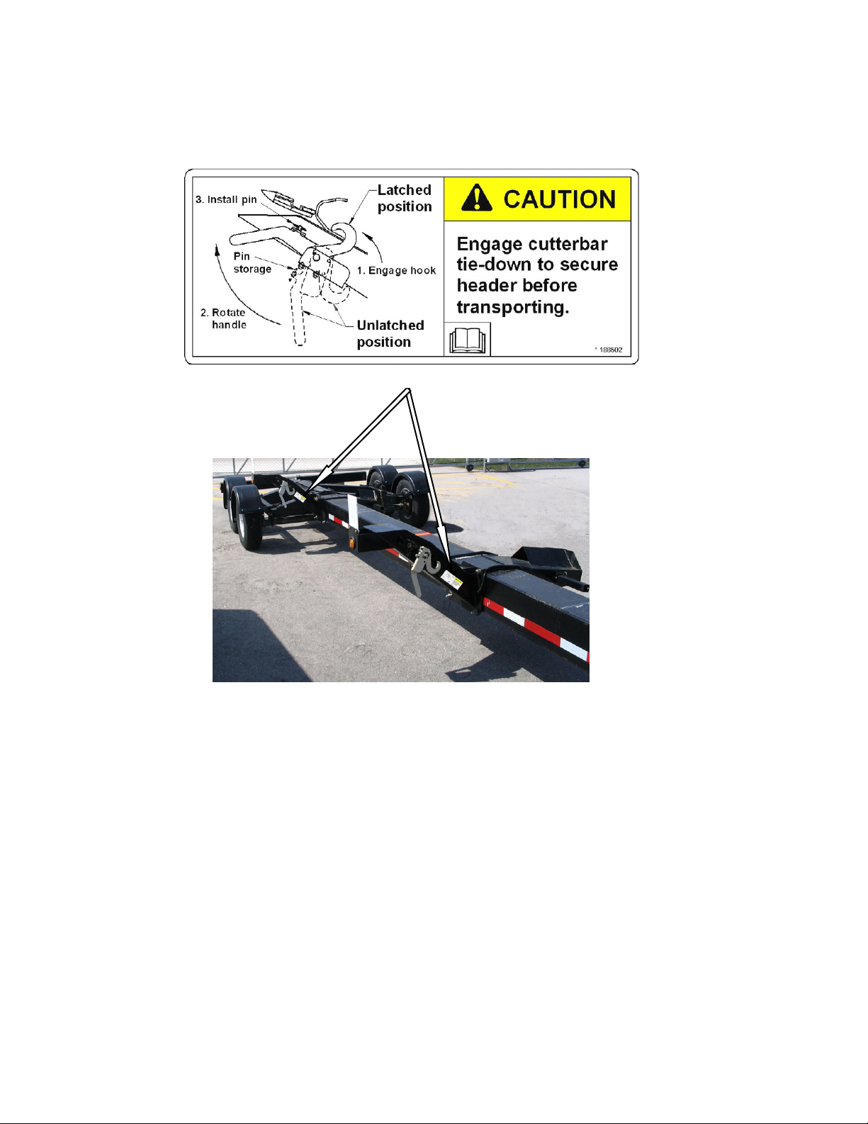
3.9.4 Engage Cutterbar Tie-downs
CAUTION
Cutterbar tie-downs must be engaged
before transporting header. Failure to do
so may result in header shifting on
transporter and damage to header or
transporter.
f. Continue to lower header until leg guides
contact supports at rear of header and header
is resting fully on the transporter.
Form # 169365 OM-21 Issue – May 2008
a. Remove lynch pin from storage location on
lever.
(continued next page)
Page 46

SECTION OM – OPERATOR’S MANUAL
b. Position hook onto cutterbar lower edge.
c. Pull lever to lock hook onto cutterbar. The tie-
down is an over-center locking system and
should require a firm pull to lock the hook.
d. Re-install lynch pin in lever to lock into
position.
e. If the cutterbar tie-down does not latch
properly, adjust as follows:
1. Check that header is properly positioned
on transporter.
3. Back-off the two nuts below pivot with
the lever in the up position.
4. Position tie-down with hook firmly
engaging the cutterbar. Tighten the two
attachment bolts.
5. Lower lever and tighten nuts slightly.
6. Raise lever. Lever should over-center
2. Loosen the two tie-down attachment
bolts.
with a firm pull. Adjust nuts as required.
7. Repeat above steps 2 to 6 for other tiedown.
Form # 169365 OM-22 Issue – May 2008
Page 47

SECTION OM – OPERATOR’S MANUAL
3.9.5 Attach Header Anchor Chain
a. If first use, undo bolt to remove retaining plate
at end of chain.
b. Install retaining plate in keyhole slot in header
RH leg with bolt removed in previous step. Do
not fully tighten as plate must be able to
swivel.
c. Swivel retaining plate and install chain in
keyhole slot. Tighten bolt on plate to secure
chain in slot.
Form # 169365 OM-23 Issue – May 2008
Page 48

SECTION OM – OPERATOR’S MANUAL
3.10 UNLOADING D SERIES
WINDROWER HEADER
a. Block the transporter wheels.
f. Remove pins from header boots.
b. Loosen bolt on anchor chain retaining plate
and swivel plate off chain.
c. Remove chain from slot.
d. Remove lynch pins from both cutterbar tie-
downs and push levers down to disengage
hooks from cutterbar.
g. Rotate latch on centerlink to down position.
h. Approach header with windrower tractor and
line up lift legs with header boots.
i. Continue forward so that tractor legs engage
header boots.
(continued next page)
e. Store lynch pin in hole provided on lever.
Form # 169365 OM-24 Issue – May 2008
Page 49

SECTION OM – OPERATOR’S MANUAL
j. Connect center link as follows:
MECHANICAL LINK – M150
1. Loosen nut and rotate barrel to adjust
length so that link lines up with header
bracket.
2. Install pin and secure with cotter pin.
3. Tighten nut against barrel. A slight tap
with a hammer is sufficient.
HYDRAULIC LINK – M200 STD, M150 OPTION
1. Activate header tilt cylinder switches in
tractor to position center link cylinder so
that it can connect to header.
n. Install pins into tractor legs to secure header
boots onto legs.
o. Back slowly away from transporter.
2. Push down on rod end of link cylinder
until hook engages pin on header and is
locked.
NOTE
If optional auto-connect system is
installed, activate link lift cylinder from in
the cab to lower center link onto header.
k. Activate header lift cylinders on tractor to lift
header slightly. Ensure that centerlink
securely engages pin on header. Raise
header fully.
l. Shutdown tractor engine and remove key.
m. Engage lift cylinder locks on tractor.
p. Secure anchor chain to transporter support
with hairpin.
q. Re-install stabilizer wheel and crop dividers
onto header.
Form # 169365 OM-25 Issue – May 2008
Page 50

SECTION OM – OPERATOR’S MANUAL
3.11 LOADING D AND FD SERIES
COMBINE HEADER
a. Set up transporter to suit your header. Refer
to Step 2. Configuring The Transporter in
SECTION UA. UNLOADING AND SETUP.
b. Block the transporter wheels.
3.11.1 Prepare the Header and Transporter
a. Raise the stabilizer wheels on header as
follows:
C
B
E
d. If loading header for the first time, remove the
two leg guides and hardware that are secured
to the transporter center support. Discard bolt
and nut.
e. Install leg guides on header as follows:
1. Raise header fully, shut down combine
engine and remove key.
2. Engage both header lift cylinder stops.
Refer to combine operator’s manual.
A
D
1. Support wheel weight by lifting slightly
with one hand on handle (A), and pull up
on handle (B) to release lock.
2. Lift wheel with handle (A) to uppermost
position and engage support channel
into slot (C) in upper support.
3. Push down on handle (B) to lock.
b. The right hand stabilizer wheel on 35 ft
headers needs to be removed prior to loading
onto two-axle and three-axle transporters.
1. Remove clevis pin (D) securing axle to
axle support.
2. Remove wheel assembly (E) and reinstall clevis pin in axle or axle support.
3. Store wheel assembly on header deck or
in truck bed.
c. If towing on road or highway with truck,
remove and store the crop dividers in location
provided on end sheet. Refer to header
Operator’s Manual.
RH LEG
LH LEG
3. Insert four bolts in each leg from inside.
NOTE
If necessary, use a pry bar to allow
installation of bolts into leg.
(continued next page)
Form # 169365 OM-26 Issue – May 2008
Page 51

SECTION OM – OPERATOR’S MANUAL
f. Locate leg guides on bolts and secure with
nuts.
g. Ensure both cutterbar tie-downs on transporter
are in the down position and the transporter is
cleared of tools or other debris that may
damage the header.
3.11.2 Loading Procedure
a. Disengage header lift cylinder stops and start
combine.
b. Approach transporter from left hand side, lining
up the mid-point of the header (center-link)
with the mid-point of the two center supports
on the transporter.
NOTE
Orange or red marking tape on the
transporter frame identifies the mid-point
between the center cutterbar supports.
Tape may need to be relocated
depending on header configuration.
Refer to SECTION UA. Step 2.
Configuring the Transporter.
TIP
Mark the center guard with fluorescent
paint/marker or equivalent to assist in
lining up header with transporter. The
center guard is at the mid-point of the
header opening.
c. Slowly continue forward until the guards touch
the white plastic stops on the transporter.
Lower header as required so that the white
plastic stops remain visible from the operator’s
station.
(continued next page)
Form # 169365 OM-27 Issue – May 2008
Page 52

SECTION OM – OPERATOR’S MANUAL
d. Slowly lower header onto transporter cutterbar
supports.
e. Back up slightly until cutterbar guard tips
approximately line up with the top plate on the
cutterbar support.
f. Continue to lower header until leg guides
contact supports at rear of header and the
header is resting fully on the transporter.
IMPORTANT
Header should rest firmly in and against
the support pockets.
RIGID HEADER – LH SUPPORT
RIGID HEADER – RH SUPPORT
FLEX HEADER – LH SUPPORT
FLEX HEADER – RH SUPPORT
g. Detach header/adapter from combine. Refer
to CA20 Combine Adapter Operator’s Manual.
h. Engage cutterbar tie-downs. Refer to
paragraph 3.9.4 Engage Cutterbar Tie-downs.
i. Attach header anchor chain. Refer to
paragraph 3.9.5 Attach Header Anchor Chain.
Form # 169365 OM-28 Issue – May 2008
Page 53

SECTION OM – OPERATOR’S MANUAL
3.12 UNLOADING D AND FD SERIES
COMBINE HEADER
a. Block the transporter wheels.
e. Leave lever in lowered position and store lynch
pin in hole provided on lever.
f. Attach combine to header/adapter. Refer to
CA20 Combine Adapter Operator’s Manual.
g. Activate header lift cylinders on combine to lift
header off transporter.
h. Back slowly away from transporter.
b. Loosen bolt on anchor chain retaining plate
and swivel plate off chain.
c. Remove chain from slot.
d. Remove lynch pins from both cutterbar tie-
downs and push levers down to disengage
hooks from cutterbar.
i. Secure anchor chain to transporter support
with hairpin.
j. Re-install stabilizer wheel (if removed) and
crop dividers onto header.
Form # 169365 OM-29 Issue – May 2008
Page 54

SECTION OM – OPERATOR’S MANUAL
3.13 ATTACHING/DETACHING CA20
COMBINE ADAPTER
The combine and CA20 Combine Adapter may
be detached from the header and then reattached with the header loaded on the MT8
transporter. Refer to the CA20 Combine
Adapter Operator’s Manual for instructions.
3.14 STORAGE
Do the following at the end of each operating
season:
a. Clean the transporter thoroughly.
CAUTION
Never use gasoline, naphtha or any
volatile material for cleaning purposes.
These materials may be toxic and/or
flammable.
b. Store in a dry, protected place if possible.
c. Repaint all worn or chipped painted surfaces to
prevent rust.
d. Apply grease to exposed threads, and sliding
surfaces of components.
e. Check for worn components and repair.
f. Check for broken components and order
replacements from your dealer. Attention to
these items right away will save time and effort
at beginning of next season.
g. Replace or tighten any missing or loose
hardware. Refer to SECTION G, Paragraph 2,
Recommended Torques.
Form # 169365 OM-30 Issue – May 2008
Page 55

SECTION OM – OPERATOR’S MANUAL
4 MAINTENANCE
4.1 RECOMMENDED SAFETY
PROCEDURES
• Park on level surface when possible.
Block wheels securely if windrower is
parked on an incline.
• Follow all safety procedures in Section
G, Paragraph 1, Safety Instructions.
4.2 LUBRICATING THE
TRANSPORTER
4.2.1 Lubricants
LUBRICANT SPEC DESCRIPTION USE
Grease SAE Multi-
Purpose.
High Temp.
Extreme Pressure
(EP). 0-1% Max
Molybdenum
Disulphide (NLGI
Grade 2).
Lithium Complex
Base.
Base Oil Viscosity
of 190-250 CST @
40C.
As Required
Unless
Otherwise
Specified.
4.2.2 Lubricant Storage
a. Use clean containers to handle all lubricants.
b. Store in an area protected from dust, moisture,
and other contaminants.
4.2.3 Greasing Requirements
Refer to Paragraph 4.5 Maintenance Schedule
for lubrication intervals.
b. Inject grease until bearings are fully packed
with grease.
c. Replace rubber end cap.
a. Remove rubber end cap to expose grease
zerk.
Form # 169365 OM-31 Issue – May 2008
Page 56

SECTION OM – OPERATOR’S MANUAL
4.3 WHEELS AND TIRES
DANGER
Stop engine and remove key from ignition
before leaving operator's seat for any
reason. A child or even a pet could
engage an idling machine.
4.3.1 Wheel Nuts
1
6
3
4
5
2
4.3.2 Wheel - Removal/Installation
DANGER
Stop engine and remove key from ignition
before leaving operator's seat for any
reason. A child or even a pet could
engage an idling machine.
4.3.2.1 Removal
IMPORTANT
If transporter is not attached to towing
vehicle, block transporter wheels to
prevent movement.
a. Loosen wheel nuts slightly.
NOTE
Minimum jack capacity – 5000 lb (2270
kg).
IMPORTANT
Check and tighten wheel nuts after the
first hour of operation and every 100
hours thereafter. Maintain 90-120 ft-lbf
(122-163 N·m) torque using tightening
sequence as shown.
IMPORTANT
Whenever a wheel is removed and reinstalled, check torque after one hour of
operation.
b. Position jack and a block under frame close to
wheel.
IMPORTANT
Ensure jack locates on flat area under
frame. Do not locate on axle as damage
may occur and result in premature
failure of the suspension system.
(continued next page)
Form # 169365 OM-32 Issue – May 2008
Page 57

SECTION OM – OPERATOR’S MANUAL
c. Operate jack to raise wheel off ground.
d. Remove wheel nuts and remove wheel.
4.3.2.2 Installation
CAUTION
When installing wheel be sure to use the
holes that are countersunk to match nut
profile. The uncountersunk holes do not
seat the nuts correctly.
IMPORTANT
Be sure valve stem (A) points away from
wheel support.
a. Position wheel on spindle and install nuts.
Partially tighten.
b. Remove blocks or stand, and lower jack until
tire contacts the ground.
1
6
4
2
c. Torque nuts to 90-120 ft-lbf (122-163 N·m) in
accordance with tightening sequence shown.
d. Lower jack completely and remove from work
area.
3
5
Form # 169365 OM-33 Issue – May 2008
Page 58

SECTION OM – OPERATOR’S MANUAL
4.3.3 Tires
WARNING
• Service tires safely.
• A tire can explode during inflation and
cause serious injury or death.
• Do not stand over tire. Use a clip-on
chuck and extension hose.
• Never increase air pressure beyond 40
psi (276 kPa) to seat the bead on the
rim.
• Replace the tire if it has a defect.
• Replace a wheel rim, which has cracks,
wear or severe rust.
• Never weld a wheel rim.
• Never use force on an inflated or
partially inflated tire.
• Make sure the tire is correctly seated
before inflating to operating pressure.
• If the tire is not in correct position on
the rim, or is too full of air, the tire bead
can loosen on one side, causing air to
leak at high speed and with great force.
An air leak of this nature can thrust the
tire in any direction, endangering
anyone in the area.
• Make sure all the air is removed from a
tire before removing the tire from a rim.
• Do not remove, install or make repairs
to a tire on a rim unless you have the
proper equipment and experience to
perform the job.
• Take the tire and rim to a qualified tire
repair shop.
4.3.3.2 Wear
a. Inspect tires as follows and in accordance with
Maintenance Schedule. See paragraph 4.5.
WEAR PATTERN CAUSE ACTION
Cupping
Out of
Balance
Center
Wear
Over
Inflation
Edge
Wear
Under
Inflation
Check Bearing
Adjustment And
Balance Tires.
Adjust Pressure
To Particular
Load Per Tire
Catalog.
Adjust Pressure
To Particular
Load Per Tire
Catalog.
Toe
Wear
Flat
Spots
Side
Wear
Incorrect
Toe-in
Wheel
Lockup and
Skidding
Loss of
Camber or
Overloading
Align.
Avoid Sudden
Stops When
Possible And
Adjust Brakes.
Ensure Load
Doesn’t Exceed
Axle Rating.
Align.
4.3.3.1 Inflation
a. Check tire pressure daily. Maintain pressure
at 65 psi (448 kPa).
Form # 169365 OM-34 Issue – May 2008
Page 59

SECTION OM – OPERATOR’S MANUAL
4.4 ELECTRICAL
4.4.1 Lights
b. Use electrical tape and wire clips as required
to prevent wires from dragging or rubbing.
c. Keep lights clean and replace burnt bulbs.
Refer to Parts Catalog.
4.4.1.1 Tail/Brake/Signal Replacement
a. Using a blade type screwdriver or equivalent,
pry light assembly from rubber mount
b. Disconnect wire and discard light assembly.
c. Connect new light assembly to wire and push
assembly into rubber mount until it is firmly
seated.
4.4.1.4 License Plate Light
a. Loosen screw and pull off cover.
b. Replace light bulb.
c. Reinstall cover and tighten screw.
4.4.2 Electric Brakes
4.4.2.1 Wiring
The transporter electric brake system is
activated when the brakes on the towing
vehicle are applied, sending an electrical
signal to the transporter brakes. Check that
the towing vehicle wiring does not activate the
brakes unless the towing vehicle brakes are
applied. See connector wiring schematic.
4.4.1.2 Clearance Lights
a. Using your fingers, pull light assembly from
rubber mount.
b. Disconnect wire and discard light assembly.
c. Connect new light assembly to wire and push
assembly into rubber mount until it is firmly
seated.
4.4.1.3 Red Light Bar
FRONT VIEW – COVER OPEN
4.4.2.2 Brake Adjustment
IMPORTANT
Adjustments to the electric brakes must
be performed by qualified service
technicians. See your MacDon dealer.
a. Pull off the lens.
b. Replace bulb and reinstall plastic lens.
Form # 169365 OM-35 Issue – May 2008
Page 60

SECTION OM – OPERATOR’S MANUAL
4.4.2.3 Breakaway Battery
a. Remove four screws and two nuts in battery
case cover.
b. Pull off cover slowly as battery is not supported
in case and may fall out.
RED
BLACK
c. Check voltage across terminals with a
voltmeter. It should read 12 volts.
d. To replace battery, pull off spade type
connectors from battery terminals and remove
battery.
e. Position new battery in case and connect blue
wire to red terminal and the white wire to the
black terminal. Refer to Parts Catalog for
battery part number.
f. Re-install cover, ensuring wiring exits the case
through the slot in the cover.
g. Secure cover with four screws and two nuts.
Form # 169365 OM-36 Issue – May 2008
Page 61

SECTION OM – OPERATOR’S MANUAL
frame, e.g. "3 Months or 3000 Miles", service the
4.5 MAINTENANCE SCHEDULE
The following maintenance schedule is a listing of
periodic maintenance procedures, organized by
service intervals. Regular maintenance is the best
insurance against early wear and untimely
breakdowns. Following this schedule will increase
machine life. For detailed instructions, refer to the
specific headings in this manual. Use the lubricant
specified in Paragraph 4.2.1, Lubricants.
Service Intervals: The recommended service
intervals are in hours of operation. Where a
service interval is given in more than one time
machine at whichever interval is reached first.
IMPORTANT
Recommended intervals are for average
conditions. Service the machine more
often if operated under adverse
conditions (severe dust, extra heavy
loads, etc.).
CAUTION
Carefully follow safety messages given
under Paragraph 4.1 Recommended
Safety Procedures.
INTERVAL SERVICE
FIRST USE
EVERY USE
WEEKLY
END OF
SEASON
3 MONTHS OR
3000 MILES
(4830 km)
6 MONTHS OR
6000 MILES
(9660 km)
12 MONTHS OR
12000 MILES
(19320 km)
* IT IS RECOMMENDED THAT ANNUAL MAINTENANCE BE DONE PRIOR TO START OF OPERATING
SEASON.
1. Check brakes operational.
2. Check breakaway system battery and switch operation.
Check tire inflation pressure – 65 psi (448 kPa).
1. Adjust brakes to proper operating clearance.
2. Check wheel nuts and adjust as required.
3. Check tires for wear, cuts, bulging, etc.
1. Check brake magnets for wear and current draw.
2. Check brake controller for correct amperage and modulation.
3. Inspect suspension for deformation, wear, and loose fasteners.
4. Visually inspect wheels for distortion, cracks, or dents.
1. Inspect brake linings for wear or contamination.
2. Inspect wiring for bare spots, fraying, etc.
3. Inspect wheel drum for abnormal wear and scoring.
4. Inspect seals for leakage. Replace if removed.
5. Visually check header support welds for cracks.
Refer To Paragraph 3.3 FIRST USE.
Refer To Paragraph 3.14 STORAGE.
Form # 169365 OM-37 Issue – May 2008
Page 62

SECTION OM – OPERATOR’S MANUAL
ACTION: 9 - Check 6 - Lubricate S - Change
↔ - Adjust
Approximate Mileage
Date
RECORD
MAINTENANCE
FIRST USE
EVERY USE
Serviced By
Refer to Paragraph 3.3, FIRST USE for checklist.
NOTE: A RECORD OF DAILY MAINTENANCE IS NOT
Breakaway Switch Operational
9
NORMALLY REQUIRED BUT IS AT THE
OWNER/OPERATOR’S DISCRETION.
Brakes Operational
9
WEEKLY
Tire Inflation
9
3 MONTHS OR 3000 MILES
(4830 km)
Brake Operating Clearance
↔
Tires
9
Wheel Nut Torque
9
6 MONTHS OR 6000 MILES
(9660 km)
Brake Magnets
9
Brake Controller
9
Suspension
9
Wheels
9
12 MONTHS OR 12000
MILES (19320 km)
Brake Linings
9
Support Welds
9
Wiring
9
Wheel Drum
9
Wheel Bearing Seals
9
Form # 169365 OM-38 Issue – May 2008
Page 63

SECTION OM – OPERATOR’S MANUAL
5 TROUBLESHOOTING
SYMPTOM PROBLEM SOLUTION
Noisy Brakes
Locking Brakes
Transporter Pulls To
One Side
Under Adjustment Adjust. *
Broken Brake Components Replace Components. *
Incorrect Brake Components Install Correct Components. *
Loose, Bent, Or Broken Brake
Components.
Faulty Controller. Test And Correct. *
Insufficient Wheel Load. Adjust System Resistor And
Under Adjustment. Adjust. *
Out-Of-Round Drums. Machine Or Replace. *
Incorrect Tire Pressure. Inflate Evenly On Both Sides
Broken Wires. Find And Repair. -
Wrong Magnet Lead Wire. Correct. *
Unmatched Tires On Same Axle. Match Tires On Same Axle. 4.3.2
Replace Components. *
Synchronize.
To Correct Pressure.
PARA-
GRAPH
*
4.3.3.1
Brakes Dragging
No Brakes
Defective Or Damaged Shoe And
Lining.
One Side Out Of Adjustment. Adjust. *
Over Adjustment. Adjust. *
Out-Of-Round Drums. Machine Or Replace. *
Incorrect Brake Components Install Correct Components. *
Loose, Bent, Or Broken Brake
Components.
Faulty Breakaway Switch. Repair Or Replace. *
Loose Wheel Bearing Adjustment. Adjust. *
Bent Spindle. Replace Axle. *
Severe Under Adjustment. Adjust *
Faulty Controller. Test And Correct. *
Short Circuits. Find And Correct. *
Open Circuits Find And Correct. *
Install New Shoe And Lining. *
Replace Components. *
Form # 169365 OM-39 Issue – May 2008
(Continued next page)
Page 64

SECTION OM – OPERATOR’S MANUAL
SYMPTOM PROBLEM SOLUTION
PARA-
GRAPH
Weak Brakes
Harsh Brakes
Surging Brakes
Brake Adjustment Not Correct. Adjust. *
Corroded Connections. Clean And Correct Cause Of
Corrosion.
Excessively Worn Brake Linings. Replace Shoe And Lining. *
Incorrect Lining. Install Correct Shoe And
Lining.
Grease Or Oil On Lining Or Magnets. Repair Grease Seal. Clean
Or Replace Linings.
Glazed Lining. Refurbish Or Replace. *
Excessive Drum Wear. Replace Drum. *
Overloaded Transporter. Correct. 2
Improper Synchronization. Correct. *
Brake Adjustment Incorrect Adjust. *
Improper Controller. Change. *
Faulty Controller. Test And Correct. *
Grease On Lining Or Magnets. Clean Or Replace. *
Out-Of-Round Drums Or Cracked
Machine Or Replace. *
Drums.
-
*
*
Intermittent Brakes
Brake/Signal Lights
Not Working
Breakaway System
Not Working
* See your MacDon dealer.
Faulty Controller. Test And Correct. *
Broken Wires. Repair Or Replace. -
Loose Connections. Find And Repair. -
Faulty Ground. Find And Repair. -
Burnt Out Bulb. Replace Bulb. 4.4.1
Broken Wire. Find And Replace. -
Towing Vehicle Problem. Find and Correct -
Faulty Switch. Repair Or Replace. *
Faulty Connections. Find And Repair -
Breakaway System Battery Dead. Replace Battery. 4.4.2.3
Form # 169365 OM-40 Issue – May 2008
Page 65

NOTES
Form # 169365 OM-41 Issue – May 2008
 Loading...