

Page 1

D1X and D1XL Series
Draper Header
Unloading and Assembly Instructions (North America)
214778 Revision A
Original Instruction
The harvesting specialists.
Page 2
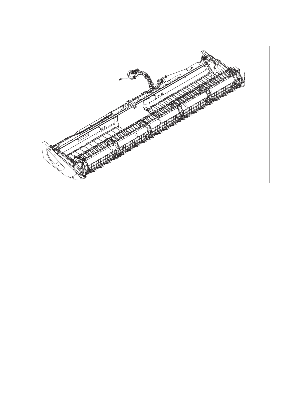
D1XL Draper Header for Self-Propelled Windrowers
1016762
Published: September 2018
Page 3

Introduction
This instruction manual describes the unloading, setup, and predelivery requirements for the MacDon D1X and D1XL Series
Draper Headers for Self-Propelled Windrowers.
To ensure the best performance of this product and the safety of your customers, carefully follow the unload and assembly
procedure from the beginning through to completion.
Some sections/steps apply to multiple header configurations and sizes. Refer to the instructions for your specific header.
Carefully read all the material provided before attempting to unload, assemble, or use the machine.
Retain this instruction for future reference.
NOTE:
Keep your MacDon publications up-to-date. The latest version can be downloaded from our website (www.macdon.com)or
from our Dealer portal (https://portal.macdon.com) (login required).
This document is currently available in English only.
214778 i Revision A
Page 4

List of Revisions
Summary of Change Refer To
Updated illustrations to include outer leg shipping supports
on 4.6–7.6 m (15–25 ft.) headers as well as 9.1–12.2 m (30–
40 ft.) headers.
2.3 Removing Shipping Supports, page 13
Included information regarding installing hose management
arm on 4.6 m (15 ft.) D1X headers.
Added note about quick-disconnect couplers/hard plumb
connections for M1 Series.
Increased detail, illustrations for topic. 4.1 Positioning Transport Lights, page 31
Included information regarding 9-bat reel arm shipping
configuration.
Included additional D1X header sizes to table. 4.7 Adding Ballast, page 47
Added illustration. 5.13 Checking Manuals, page 75
3.1 Installing the Hydraulic Hose Management Arm, page
17
3.4 Connecting Hydraulics, page 28
4.4 Attaching Cam Arms, page 42
214778 ii Revision A
Page 5

TABLE OF CONTENTS
Introduction ................................................................................................................................................i
List of Revisions...........................................................................................................................................ii
Chapter 1: Safety ........................................................................................................................................ 1
1.1 Signal Words .........................................................................................................................................1
1.2 General Safety .......................................................................................................................................2
1.3 Safety Signs ...........................................................................................................................................4
Chapter 2: Unloading.................................................................................................................................. 5
2.1 Unloading Header from Trailer..................................................................................................................5
2.2 Lowering Header ....................................................................................................................................7
2.2.1 Lowering Single-Reel Header..... .......................................................................................................7
2.2.2 Lowering Double-Reel Header ........................................................................................................ 10
2.3 Removing Shipping Supports .................................................................................................................. 13
Chapter 3: Attaching Header to Windrower ........................................................................................... 17
3.1 Installing the Hydraulic Hose Management Arm ......................................................................................... 17
3.2 Attaching Draper Header Supports .......................................................................................................... 22
3.3 Connecting Center-Link.......................................................................................................................... 23
3.4 Connecting Hydraulics ........................................................................................................................... 28
Chapter 4: Assembling the Header .......................................................................................................... 31
4.1 Positioning Transport Lights ................................................................................................................... 31
4.2 Attaching Reel Lift Cylinders ................................................................................................................... 33
4.3 Installing Disc Segments of Outboard Reel Endshields ................................................................................. 41
4.4 Attaching Cam Arms ............................................................................................................................. 42
4.5 Installing Crop Dividers .......................................................................................................................... 44
4.6 Installing Options ................................................................................................................................. 46
4.7 Adding Ballast ...................................................................................................................................... 47
Chapter 5: Performing Predelivery Checks.............................................................................................. 49
5.1 Checking Tire Pressure – Transport and Stabilizer Wheels ............................................................................ 49
5.2 Checking Wheel Bolt Torque................................................................................................................... 50
5.3 Checking Knife Drive Box ... .................................................................................................................... 51
5.4 Checking and Adjusting Knife Drive Belt Tension ..... . .................................................................................. 53
5.4.1 Checking and Tensioning ............................................................................................................... 53
5.4.2 Tensioning Timed Knife Drive Belts ................................................................................................. 54
5.4.3 Tensioning Timed Knife Drive V-Belts............................................................................................... 56
5.5 Centering the Reel ................................................................................................................................ 57
5.5.1 Centering Double Reels ................................................................................................................. 57
5.5.2 Centering Single Reel .................................................................................................................... 58
5.6 Adjusting Draper Tension ....................................................................................................................... 59
214778 iii Revision A
Page 6

TABLE OF CONTENTS
5.7 Checking and Adjusting Draper Seal ......................................................................................................... 61
5.8 Checking and Adjusting Skid Shoe Settings ................................................................................................ 63
5.9 Leveling the Header .............................................................................................................................. 64
5.10 Measuring and Adjusting Reel Clearance to Cutterbar ............................................................................... 65
5.10.1 Measuring Reel Clearance............................................................................................................ 65
5.10.2 Adjusting Reel Clearance ............................................................................................................. 67
5.11 Checking and Adjusting Endshields......................................................................................................... 68
5.12 Lubricating the Header . ....................................................................................................................... 72
5.12.1 Greasing Procedure .................................................................................................................... 72
5.12.2 Lubrication Points ...................................................................................................................... 73
5.13 Checking Manuals............................................................................................................................... 75
Chapter 6: Running up the Header .......................................................................................................... 77
Chapter 7: Performing Post Run-Up Adjustments .................................................................................. 79
7.1 Adjusting Knife ..................................................................................................................................... 79
Chapter 8: Reference................................................................................................................................ 81
8.1 Torque Specifications ............................................................................................................................ 81
8.1.1 SAE Bolt Torque Specifications ....................................................................................................... 81
8.1.2 Metric Bolt Specifications .............................................................................................................. 83
8.1.3 Metric Bolt Specifications Bolting into Cast Aluminum ........................................................................ 85
8.1.4 Flare-Type Hydraulic Fittings ..... ..................................................................................................... 86
8.1.5 O-Ring Boss (ORB) Hydraulic Fittings – Adjustable .............................................................................. 87
8.1.6 O-Ring Boss (ORB) Hydraulic Fittings – Non-Adjustable ....................................................................... 89
8.1.7 O-Ring Face Seal (ORFS) Hydraulic Fittings ........................................................................................ 90
8.1.8 Tapered Pipe Thread Fittings.......................................................................................................... 92
8.2 Lifting Equipment Requirements ............................................................................................................. 93
8.3 Conversion Chart .................................................................................................................................. 94
8.4 Definitions .......................................................................................................................................... 95
Predelivery Checklist ................................................................................................................................ 99
214778 iv Revision A
Page 7

Chapter 1: Safety
1.1 Signal Words
Three signal words, DANGER, WARNING, and CAUTION, are used to alert you to hazardous situations. Two signal words,
IMPORTANT and NOTE identify non-safety related information. Signal words are selected using the following guidelines:
DANGER
Indicates an imminently hazardous situation that, if not avoided, will result in death or serious injury.
WARNING
Indicates a potentially hazardous situation that, if not avoided, could result in death or serious injury. It may also be
used to alert against unsafe practices.
CAUTION
Indicates a potentially hazardous situation that, if not avoided, may result in minor or moderate injury. It may be used
to alert against unsafe practices.
IMPORTANT:
Indicates a situation that, if not avoided, could result in a malfunction or damage to the machine.
NOTE:
Provides additional non-essential information or advice.
214778 1 Revision A
Page 8
1000004
1000005
1010391
SAFETY
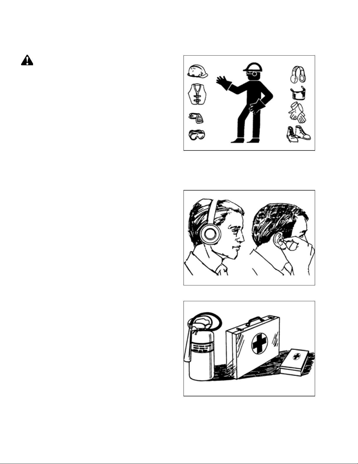
1.2 General Safety
CAUTION
The following are general farm safety precautions that should
be part of your operating procedure for all types of machinery.
Protect yourself.
• When assembling, operating, and servicing machinery, wear
all protective clothing and personal safety devices that could
be necessary for job at hand. Do NOT take chances. You may
need the following:
• Hard hat
• Protective footwear with slip-resistant soles
• Protective glasses or goggles
• Heavy gloves
• Wet weather gear
• Respirator or filter mask
• Be aware that exposure to loud noises can cause hearing
impairment or loss. Wear suitable hearing protection devices
such as earmuffs or earplugs to help protect against loud
noises.
• Provide a first aid kit for use in case of emergencies.
• Keep a fire extinguisher on the machine. Be sure fire
extinguisher is properly maintained. Be familiar with its
proper use.
Figure 1.1: Safety Equipment
Figure 1.2: Safety Equipment
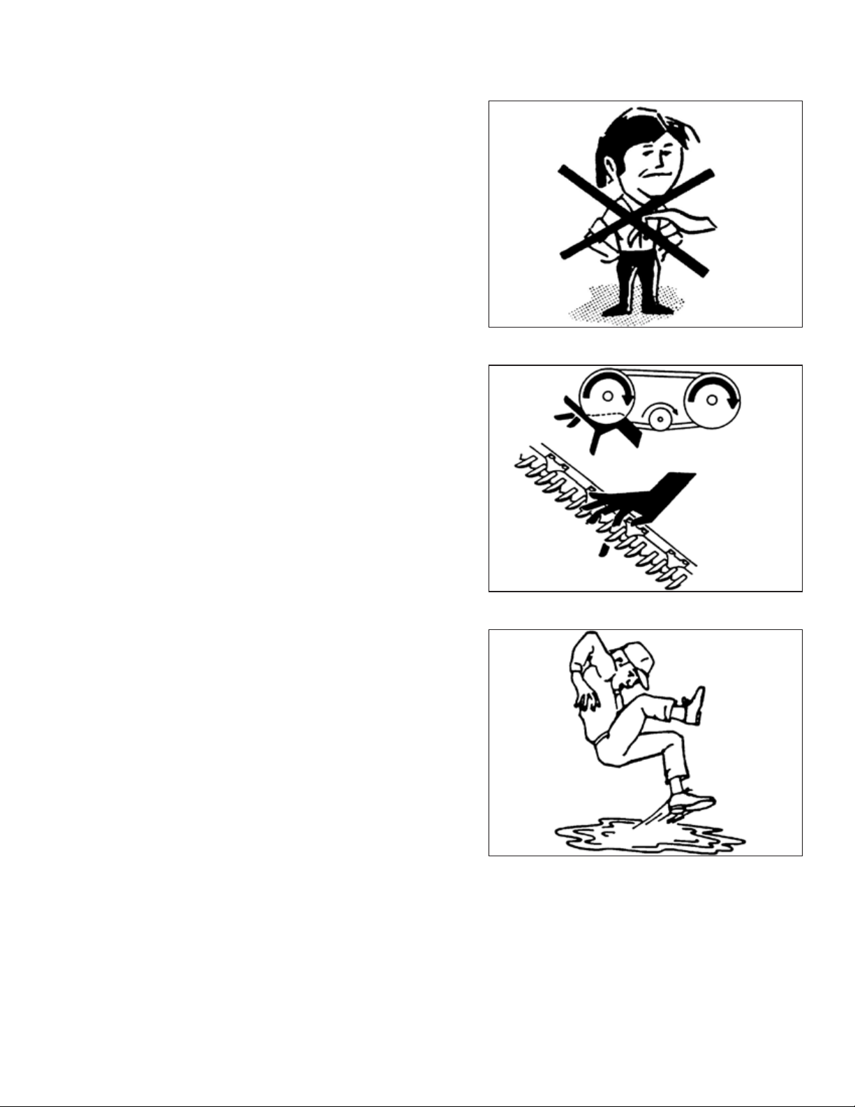
• Keep young children away from machinery at all times.
• Be aware that accidents often happen when Operator is tired
or in a hurry. Take time to consider safest way. NEVER ignore
warning signs of fatigue.
Figure 1.3: Safety Equipment
214778 2 Revision A
Page 9
1000007
1000008
1000009
SAFETY
• Wear close-fitting clothing and cover long hair. NEVER wear
dangling items such as scarves or bracelets.
• Keep all shields in place. NEVER alter or remove safety
equipment. Make sure driveline guards can rotate
independently of shaft and can telescope freely.
• Use only service and repair parts made or approved by
equipment manufacturer. Substituted parts may not meet
strength, design, or safety requirements.
• Keep hands, feet, clothing, and hair away from moving parts.
NEVER attempt to clear obstructions or objects from a
machine while engine is running.
• Do NOT modify machine. Unauthorized modifications may
impair machine function and/or safety. It may also shorten
machine’s life.
Figure 1.4: Safety around Equipment
• To avoid bodily injury or death from unexpected startup of
machine, ALWAYS stop the engine and remove the key from
the ignition before leaving the operator’s seat for any reason.
• Keep service area clean and dry. Wet or oily floors are
slippery. Wet spots can be dangerous when working with
electrical equipment. Be sure all electrical outlets and tools
are properly grounded.
• Keep work area well lit.
• Keep machinery clean. Straw and chaff on a hot engine is a
fire hazard. Do NOT allow oil or grease to accumulate on
service platforms, ladders, or controls. Clean machines before
storage.
• NEVER use gasoline, naphtha, or any volatile material for
cleaning purposes. These materials may be toxic and/or
flammable.
• When storing machinery, cover sharp or extending
components to prevent injury from accidental contact.
Figure 1.5: Safety around Equipment
Figure 1.6: Safety around Equipment
214778 3 Revision A
Page 10
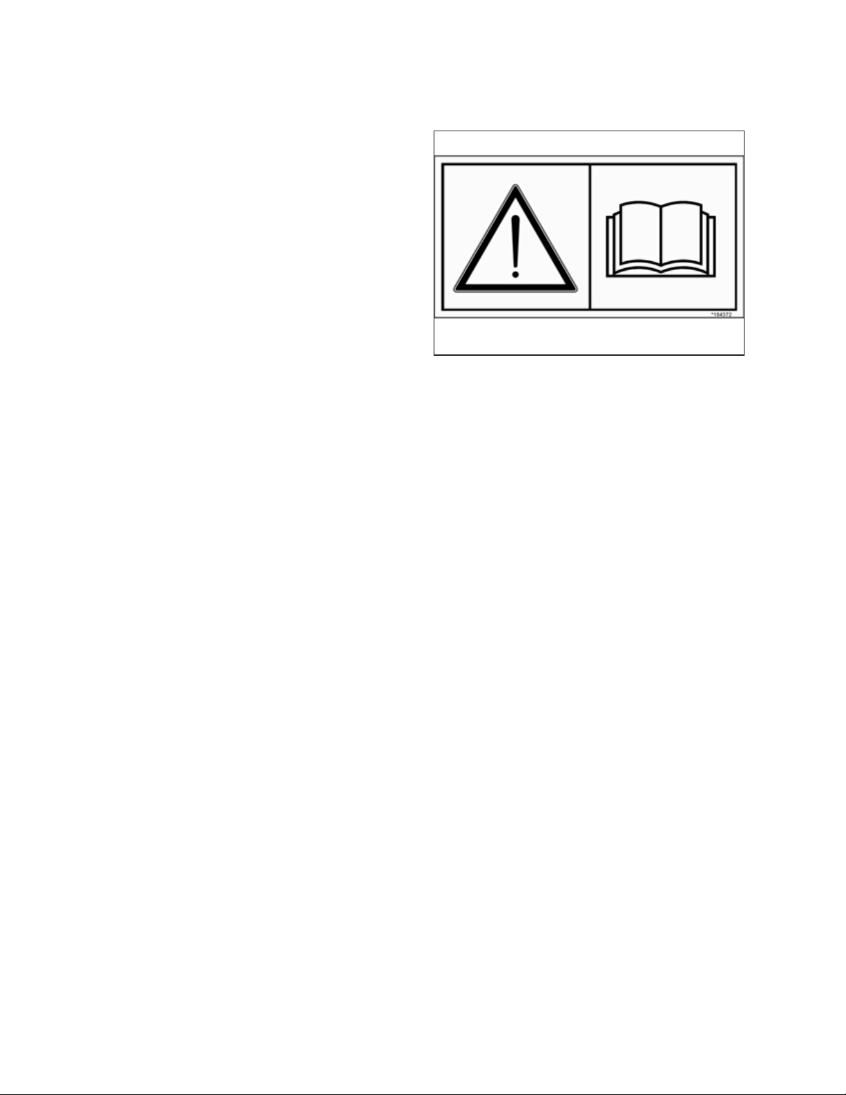
1.3 Safety Signs
1000694
• Keep safety signs clean and legible at all times.
• Replace safety signs that are missing or illegible.
• If original part on which a safety sign was installed is
replaced, be sure the repair part displays the current
safety sign.
• Safety signs are available from your MacDon Dealer.
SAFETY
Figure 1.7: Operator’s Manual Decal
214778 4 Revision A
Page 11
Chapter 2: Unloading
1013855
A
B
C
Perform all procedures in this chapter in the order they are listed.
2.1 Unloading Header from Trailer
The following procedure assumes that two headers were shipped on the trailer.
CAUTION
To avoid injury to bystanders from being struck by machinery, do not allow people to stand in unloading area.
CAUTION
Equipment used for unloading must meet or exceed the requirements specified below. Using inadequate equipment
may result in chain breakage, vehicle tipping, or machine damage.
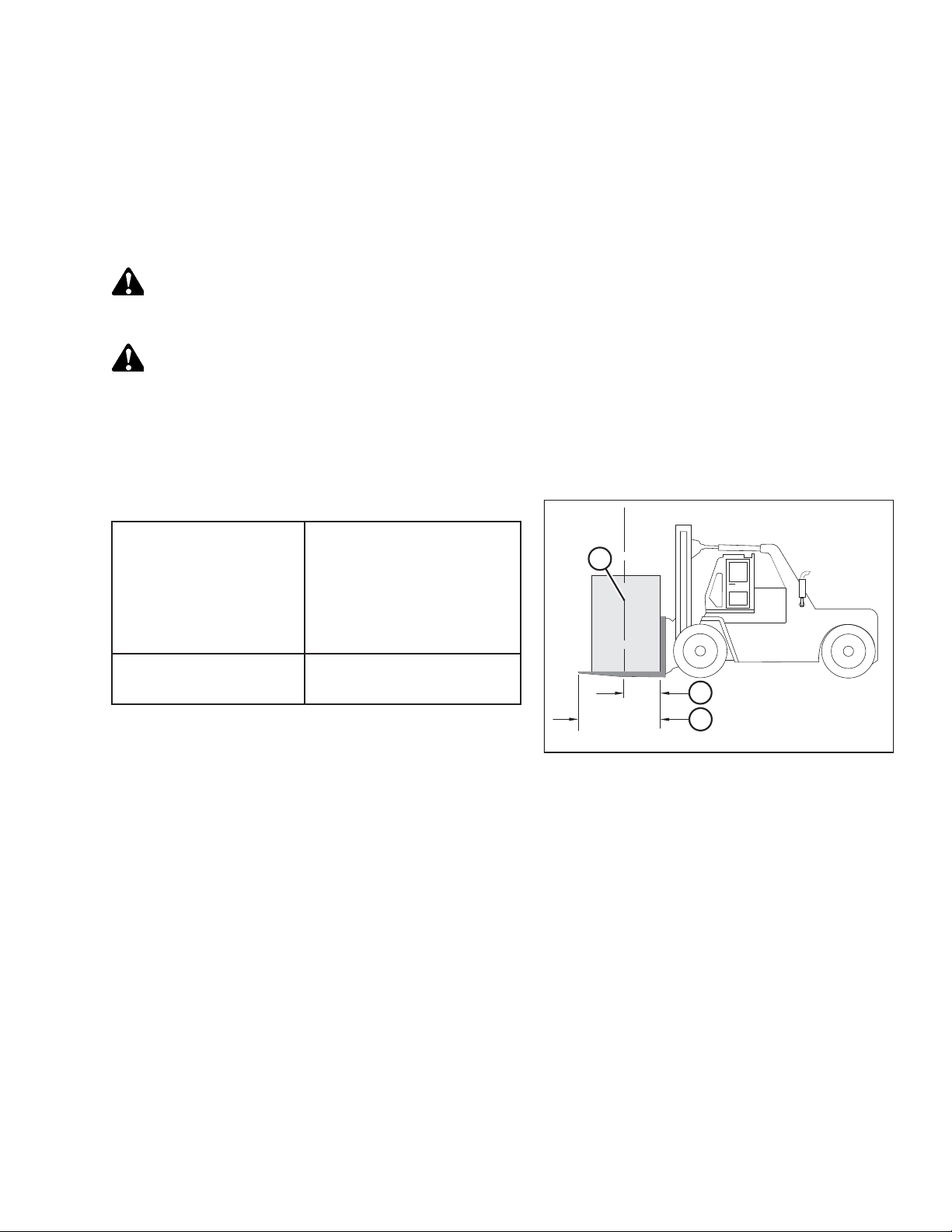
IMPORTANT:
Forklifts are normally rated with the load centered 610 mm (24 in.) from the back end of forks. To obtain forklift capacity
for a load centered at 1220 mm (48 in.), check with your forklift distributor.
Table 2.1 Lifting Vehicle
3178 kg (7000 lb.) load center
Minimum Lifting Capacity
(A) at 1220 mm (48 in.) (B)
from back of forks
Minimum Fork Length (C) 1981 mm (78 in.)
Figure 2.1: Minimum Lifting Capacity
A - Load Center of Gravity
B - Load Center 1220 mm (48 in.) from Back of Forks
C - Minimum Fork Length 1981 mm (78 in.)
To unload headers from a trailer, follow these steps:
1. Move trailer into position and block trailer wheels.
2. Lower trailer storage stands.
214778 5 Revision A
Page 12
1008902
A
B
C
UNLOADING
3. Approach one of the headers and slide forks (A) underneath
the shipping support (B) as far as possible without
contacting the shipping support of second header (C).
IMPORTANT:
Avoid lifting the second header and ensure the forks do not
interfere with the shipping frame. If the forks contact the
second header, the header could be damaged.
4. Remove hauler’s tie-down straps, chains, and wooden
blocks.
5. Slowly raise header off trailer deck.
WARNING
Be sure forks are secure before moving away from load. Stand
clear when lifting.
6. Back up until header clears trailer and slowly lower to
150 mm (6 in.) from ground.
7. Take header to the storage or setup area. Ensure ground is
flat and free of rocks or debris that could damage the
header.
8. Repeat above steps for second header.
9. Check for shipping damage and missing parts.
Figure 2.2: Header Shipping Supports
214778 6 Revision A
Page 13

1008905
A
B
UNLOADING
2.2 Lowering Header
The procedure for lowering the header varies depending on whether the header has a single or double reel. Refer to the
following:
• 2.2.1 Lowering Single-Reel Header, page 7
• 2.2.2 Lowering Double-Reel Header, page 10
2.2.1 Lowering Single-Reel Header
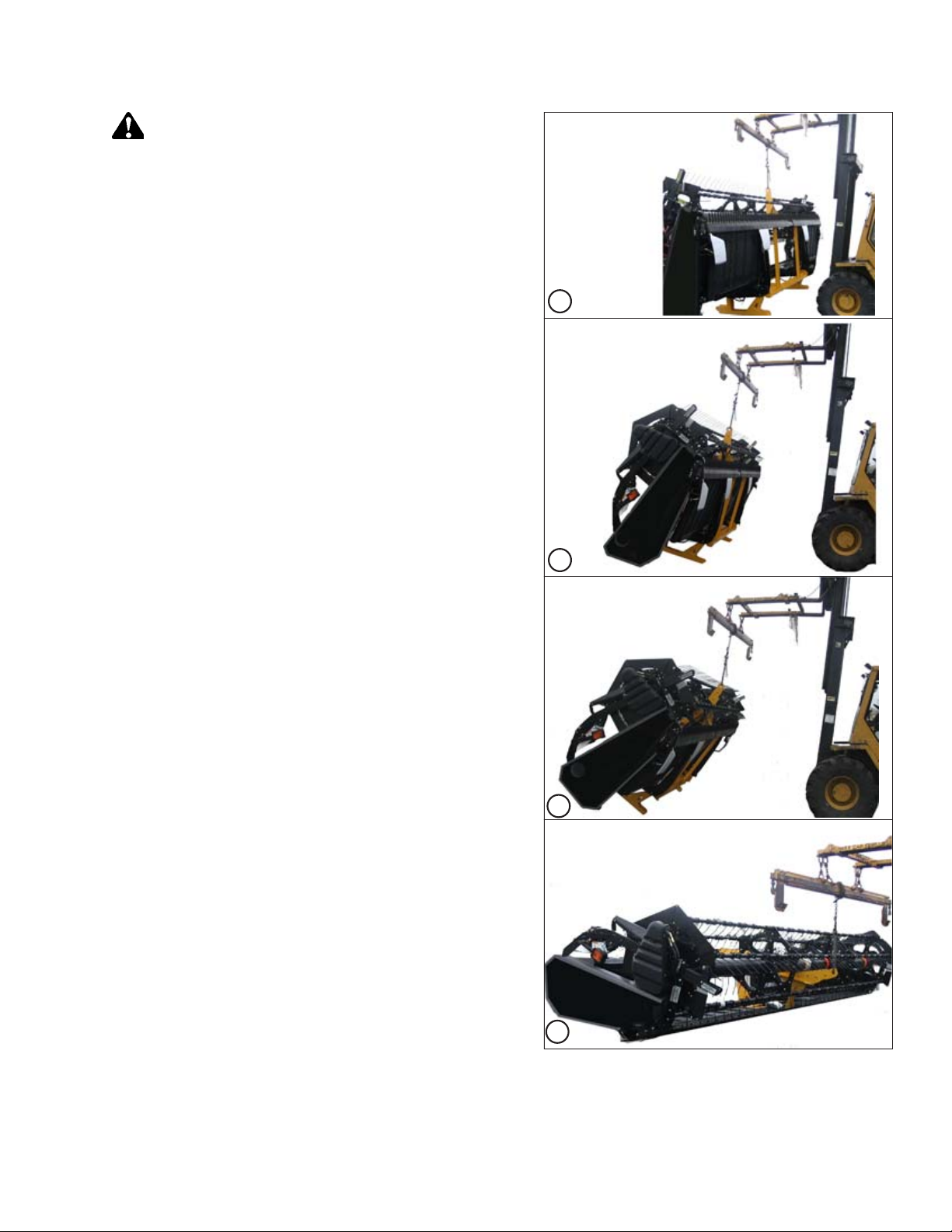
Reposition header in preparation for assembly and setup as follows:
1. Choose an area with level ground.
2. Approach header from its underside and place forks under
top of shipping frame (A).
3. Attach a chain (B) at each end of the shipping frame and
secure other end to lifting vehicle.
Figure 2.3: Shipping Frame
214778 7 Revision A
Page 14
1008906
1
2
3
4
CAUTION
Stand clear when lowering, as machine may swing.
4. Back up SLOWLY while lowering forks until header is just
above the ground. Refer to the four positions in the
illustration.
UNLOADING
Figure 2.4: Lowering the Header
214778 8 Revision A
Page 15

1006363
A
1008297
A
B
UNLOADING
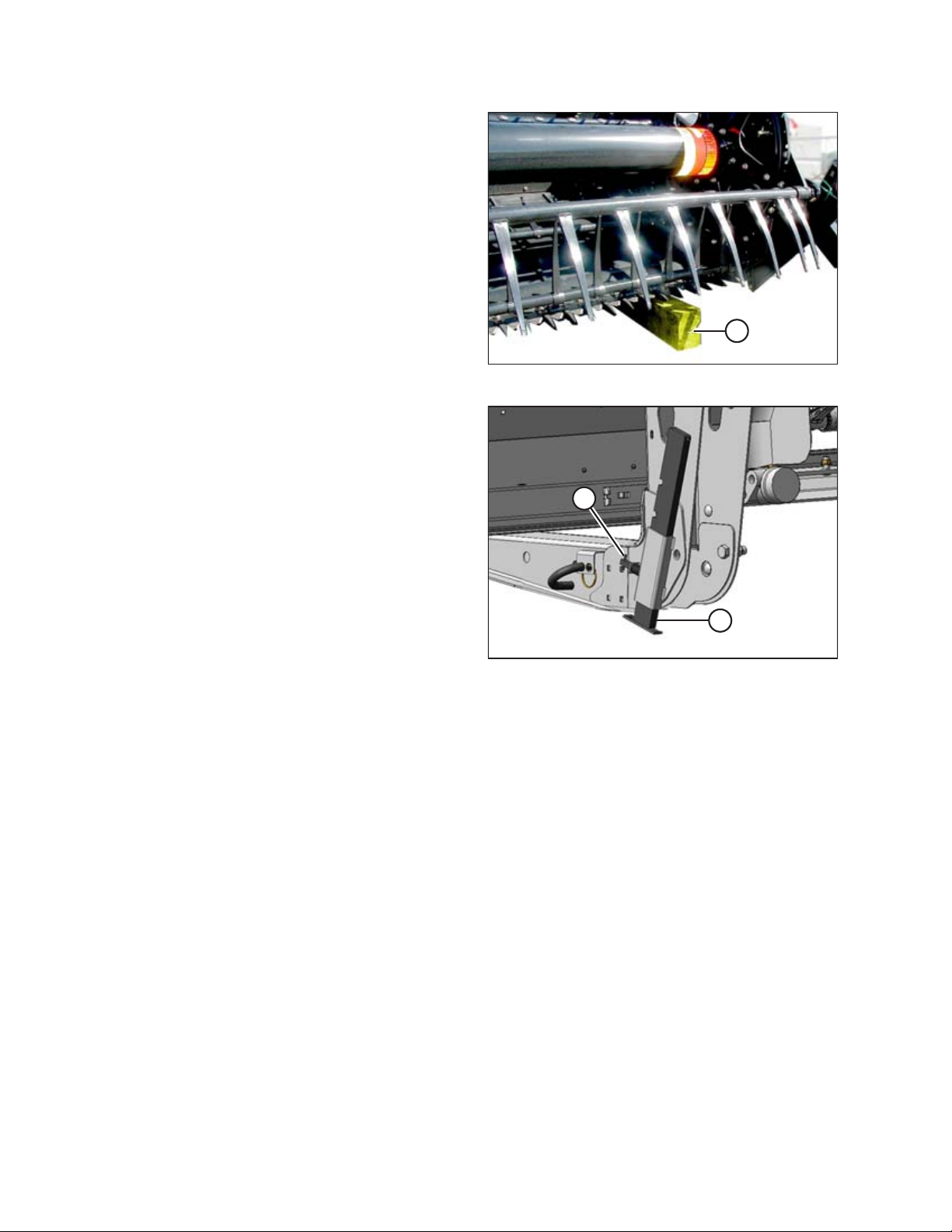
5. Place 150 mm (6 in.) blocks (A) under each end and center
of cutterbar, and then lower header onto blocks.
6. Remove chain and move lifting vehicle to rear of header.
7. Attach chain to center-link anchor on frame tube and raise
rear of header so that stand can be lowered.
8. Lower header stand by pulling pin (A), lowering stand (B),
and releasing pin (A) to secure stand in place.
9. If ground is soft, place a block under the stand.
10. Lower header onto stand.
Figure 2.5: Block under Cutterbar
Figure 2.6: Header Stand
214778 9 Revision A
Page 16
1016592
1016590
A
UNLOADING
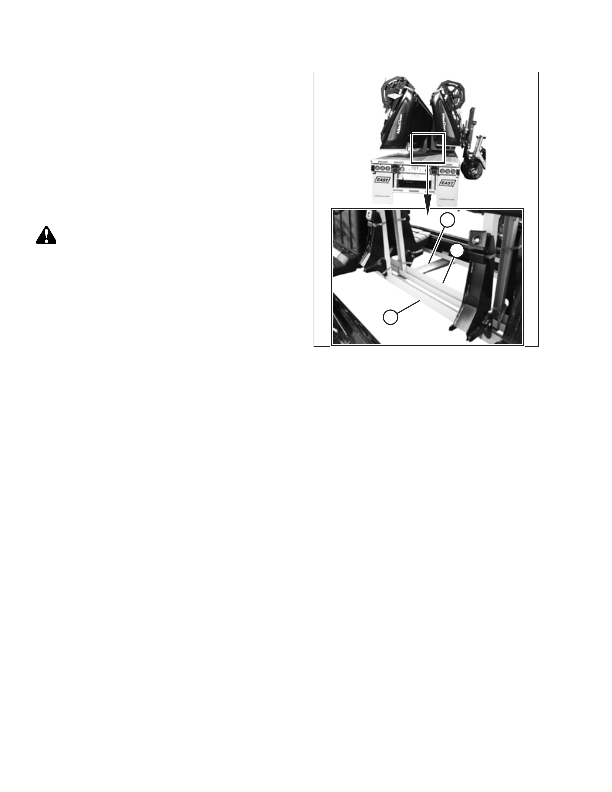
2.2.2 Lowering Double-Reel Header
Reposition header in preparation for assembly and setup as follows:
1. Choose an area with level ground.
2. Drive lifting vehicle to approach header from its underside.
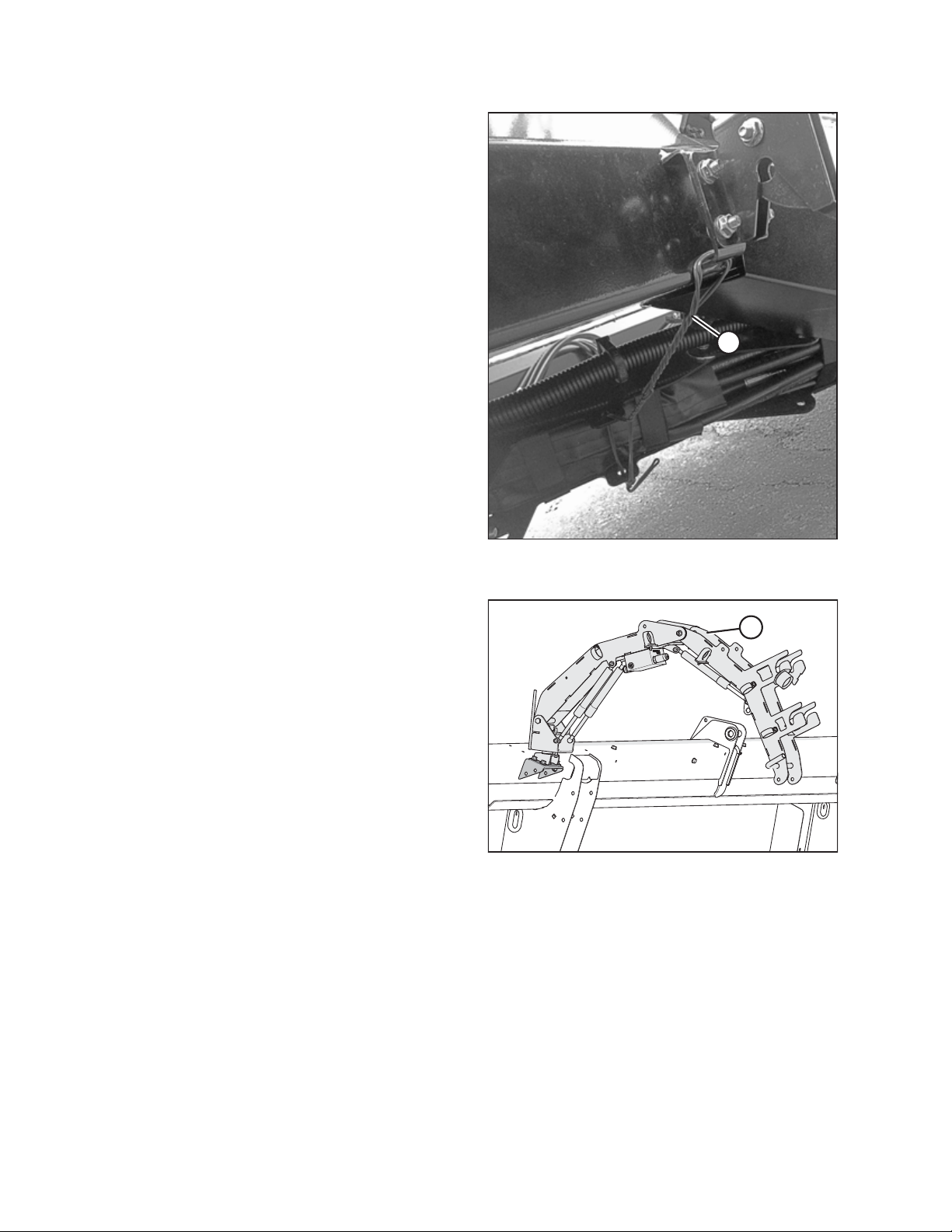
3. Attach a chain to shipping support (A) at center reel arm.
IMPORTANT:
Do NOT lift header at this location. This procedure is only
for laying the machine over into working position.
Figure 2.7: Underside of Header
Figure 2.8: Shipping Support
214778 10 Revision A
Page 17
1008121
1
2
3
4
UNLOADING
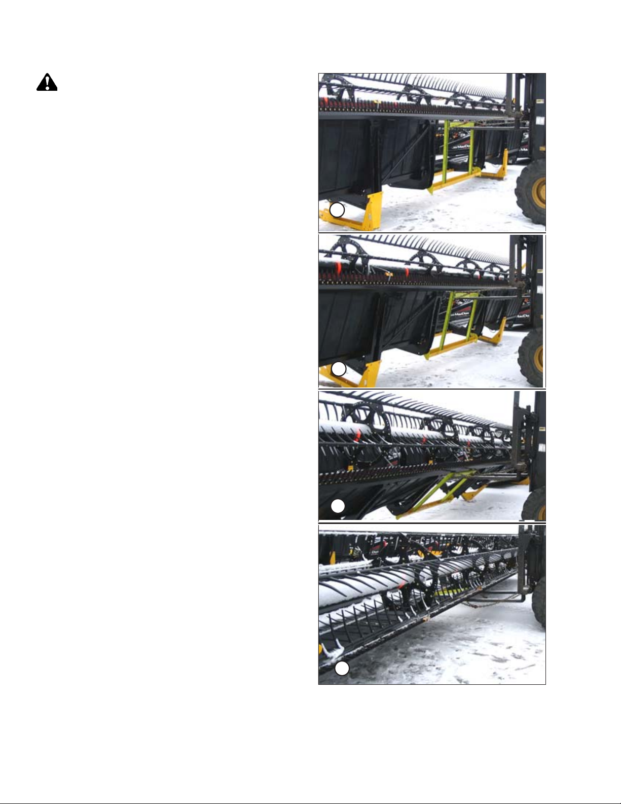
CAUTION
Stand clear when lowering, as machine may swing.
4. Back up SLOWLY while lowering forks until header is just
above the ground. Refer to the four positions in the
illustration.
Figure 2.9: Lowering the Header
214778 11 Revision A
Page 18
1006363
A
1008297
A
B
UNLOADING
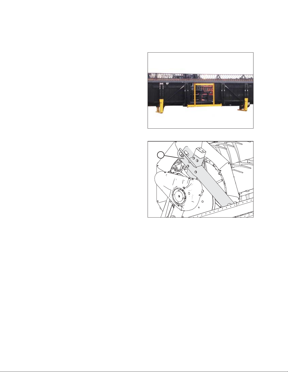
5. Place 150 mm (6 in.) blocks (A) under each end and center
of cutterbar, and then lower header onto blocks.
6. Remove chain and move lifting vehicle to rear of header.
7. Attach chain to center-link anchor on frame tube and raise
rear of header so that stand can be lowered.
8. Lower the header stand: pull pin (A), lower stand (B), and
release pin (A) to secure stand in place.
9. If ground is soft, place a block under the stand.
10. Lower header onto stand.
Figure 2.10: Block under Cutterbar
11. Remove chain.
Figure 2.11: Header Stand
214778 12 Revision A
Page 19
1016847
A
1008913
A
1016591
A
B
UNLOADING
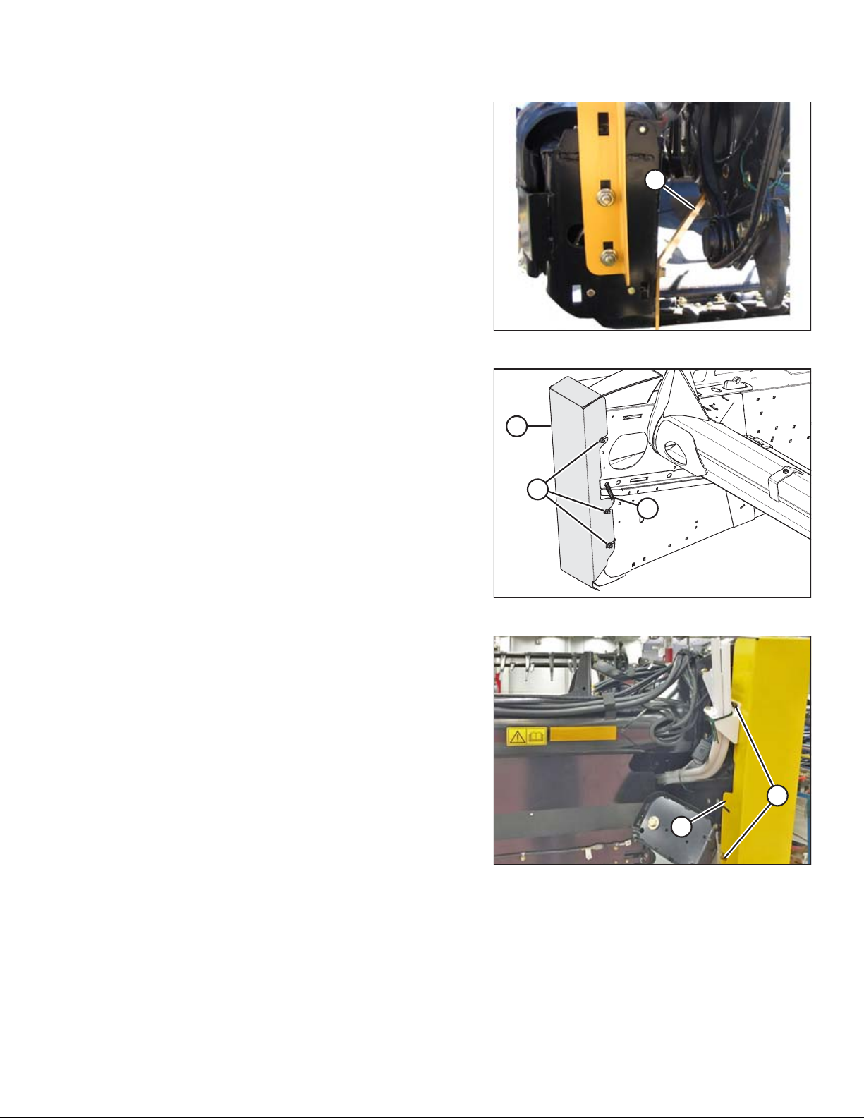
2.3 Removing Shipping Supports
NOTE:
Unless otherwise specified, discard all shipping materials and hardware.
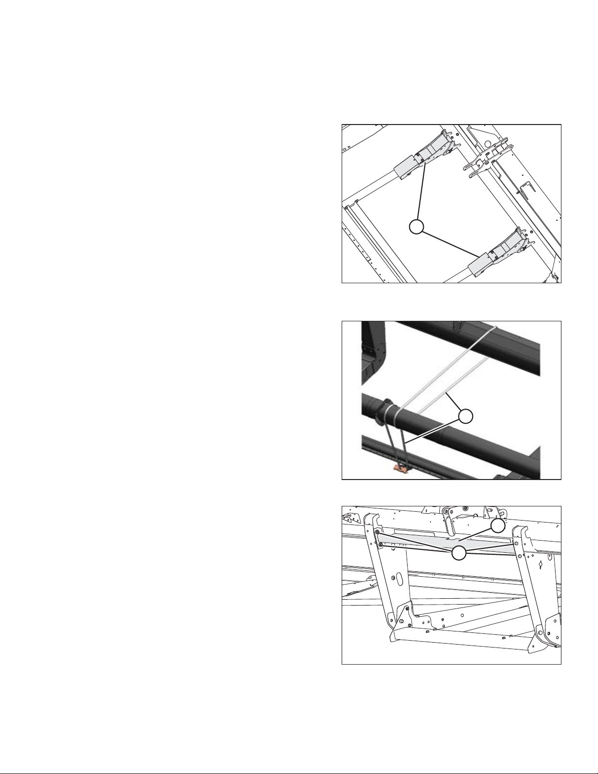
1. Cut straps and remove draper header supports (A) from
shipping support. Set draper header supports aside for
installation.
Figure 2.12: Draper Header Supports and Shipping
Supports
2. Single reel only: Cut banding (A) securing reel to cutterbar
and backtube.
3. Remove four bolts (A) securing upper support (B) to header
legs and remove support.
Figure 2.13: Single Reel
Figure 2.14: Upper Support
214778 13 Revision A
Page 20
1016855
A
B
A
1016583
A
1026957
A
UNLOADING
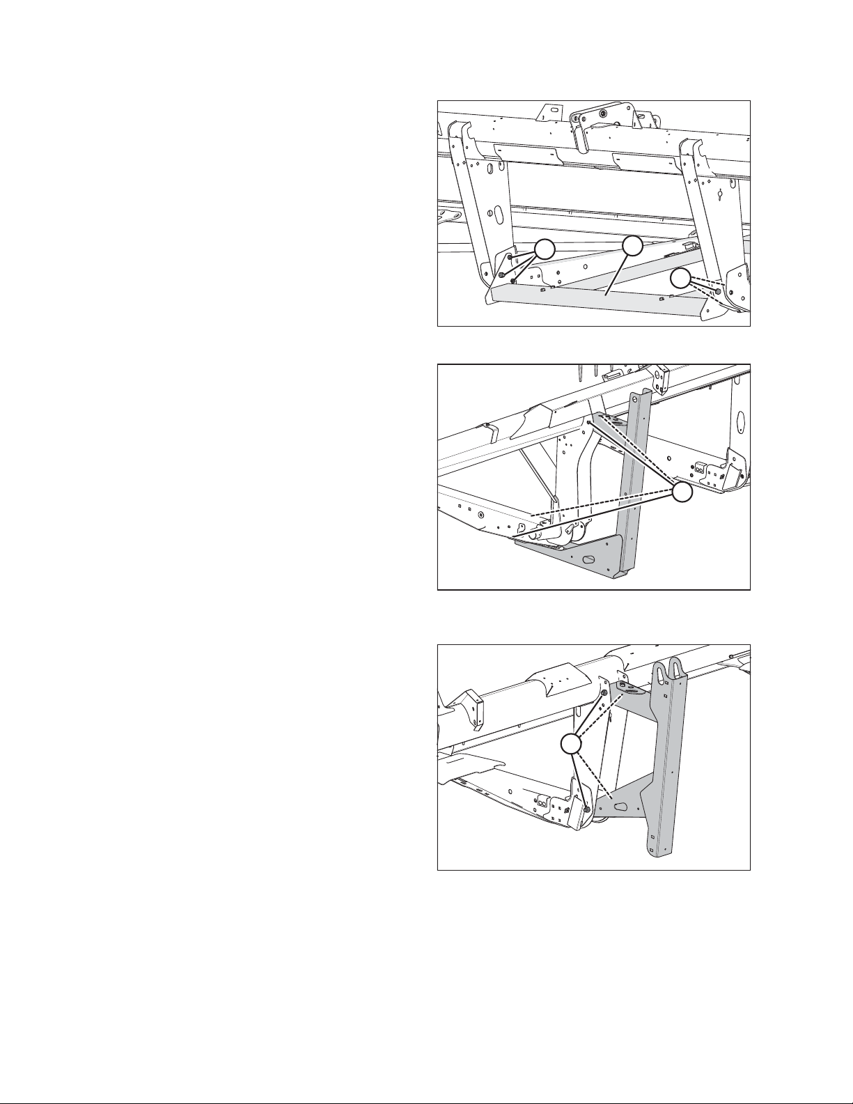
4. Remove six bolts (A) securing lower support (B) to header
legs and remove support.
5. Remove the four bolts (A) from the shipping stands at both
outboard header legs and remove the shipping stands.
Figure 2.15: Lower Support
Figure 2.16: Outer Leg Shipping Support – 9.1–12.2 m
(30–40 ft.)
Figure 2.17: Outer Leg Shipping Support – 4.6–7.6 m
(15–25 ft.)
214778 14 Revision A
Page 21
1008914
A
1026969
A
C
B
1017803
A
B
UNLOADING
6. Remove reel anti-rotation brace (A) from between reel and
endsheet.
7. At the left side of the header, cut and remove the wire (A)
securing the endshield to the panel. Repeat at the
opposite side.
8. Loosen the three nuts (B) securing the shipping support to
the endsheet.
Figure 2.18: Anti-Rotation Brace
9. Slide shipping support (C) backward to remove.
10. Tighten nuts (B).
11. At the right side of the header, loosen the two nuts (A)
securing the shipping support (B) to the endsheet.
12. Slide shipping support (B) backward to remove.
13. Tighten nuts (A).
Figure 2.19: Endsheet Shipping Support
Figure 2.20: Endsheet Shipping Support
214778 15 Revision A
Page 22

Page 23
Chapter 3: Attaching Header to Windrower
1024555
A
B
1017826
A
B
C
Perform all the procedures in this chapter in the order in which they are listed.
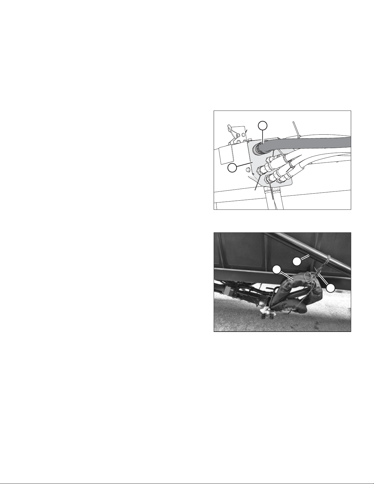
3.1 Installing the Hydraulic Hose Management Arm
The hydraulic hose management arm should be properly installed from shipping position to working position. Lifting
equipment is required to complete this task; the hydraulic hose management arm weighs approximately 54 kg (120 lb.).
1. Disconnect harness connector (A) from the header’s
coupler holder (B).
NOTE:
The harness connector must be disconnected from the
header prior to moving the hose management arm to field
position.
Figure 3.1: Hoses and Connector Attached to
the Header
2. Cut and remove the wire (A) securing the hydraulic hose
management arm (B) to the diagonal brace (C).
Figure 3.2: Hydraulic Hose Management Arm
214778 17 Revision A
Page 24
1020177
A
B
C
1027043
A
B
D
C
1020180
E
B
C
A
DD
ATTACHING HEADER TO WINDROWER
NOTE:
Hydraulic hoses were removed from the illustrations in this
procedure for clarity.
3. Position a sling (A) between the gas spring cylinder (B) and
secure around the support arm (C).
NOTE:
Illustration shows hydraulic hose management arm in
shipping position for a 7.6–10.6 m (25–35 ft.) header.
4. Attach sling (A) to forklift or lifting device.
5. 4.6 m (15 ft.) and 6.1 m (20 ft.) Headers: With the sling
attached to the lifting device and supporting the hose
management arm (A), lift the hydraulic hose management
arm (A) out of the inboard shipping stand (B) and remove
the two bolts and nuts (C) securing shipping stand (B) to
center anchor (D). Retain hardware.
Figure 3.3: Hydraulic Hose Management Arm in
Shipping Position
NOTE:
Sling not shown in illustration.
6. 7.6–10.6 m (25–35 ft.) Headers: Remove the two bolts and
nuts (A) securing the base of the hose management arm (B)
to the frame channel (C). Retain bolts and nuts for use later.
7. Remove the other two bolts and nuts (D) from the shipping
plate (E). Retain bolts and nuts for use later. Discard
shipping plate (E).
Figure 3.4: Hydraulic Hose Management Arm In
Shipping Position – 4.6 m (15 ft.) and 6.1 m (20 ft.)
Headers
214778 18 Revision A
Figure 3.5: Hydraulic Hose Management Arm
Base Frame – 7.6–10.6 m (25– 35 ft.) Headers
Page 25
1027044
A
B
B
B
B
C
D
D
E
E
C
1020181
A
C
B
ATTACHING HEADER TO WINDROWER
8. 4.6 m (15 ft.) and 6.1 m (20 ft.) Headers: With the sling
attached to the lifting device and supporting the hose
management arm (A), remove the two bolts and nuts (B)
securing the hose management arm to outboard shipping
support (C). Retain hardware.
NOTE:
Sling not shown in illustration.
9. Remove bolts and nuts (D) securing shipping support (C) to
the frame channel (E). Discard shipping support (C).
10. 7.6–10.6 m (25–35 ft.) Headers: With the sling attached to
the lifting device and supporting the hose management
arm (A), remove the two bolts and nuts (B) that secure the
hose management arm to the shipping support (C).
Figure 3.6: Hydraulic Hose Management Arm In
Shipping Position – 4.6 m (15 ft.) and 6.1 m (20 ft.)
Headers
Figure 3.7: Hydraulic Hose Management Arm in
Shipping Position – 7.6–10.6 m (25–35 ft.) Headers
214778 19 Revision A
Page 26
1017833
A
1016797
A
ATTACHING HEADER TO WINDROWER
11. 12.2–13.7 m (40–45 ft.) Headers: With the sling attached to
the lifting device and supporting the hose management
arm, cut and remove the wire (A) that secures the hose
management arm to channel latch on top of header
frame tube.
12. With the help of the sling and lifting device, position the
hose management arm (A) as shown.
NOTE:
Sling not shown in illustration.
Figure 3.8: Hose Management Arm in Shipping
Position – 12.2–13.7 m (40–45 ft.) Headers
Figure 3.9: Hose Management Arm in Field Position
214778 20 Revision A
Page 27
1017806
A
B
1020182
C
B
A
1024557
A
B
C
ATTACHING HEADER TO WINDROWER
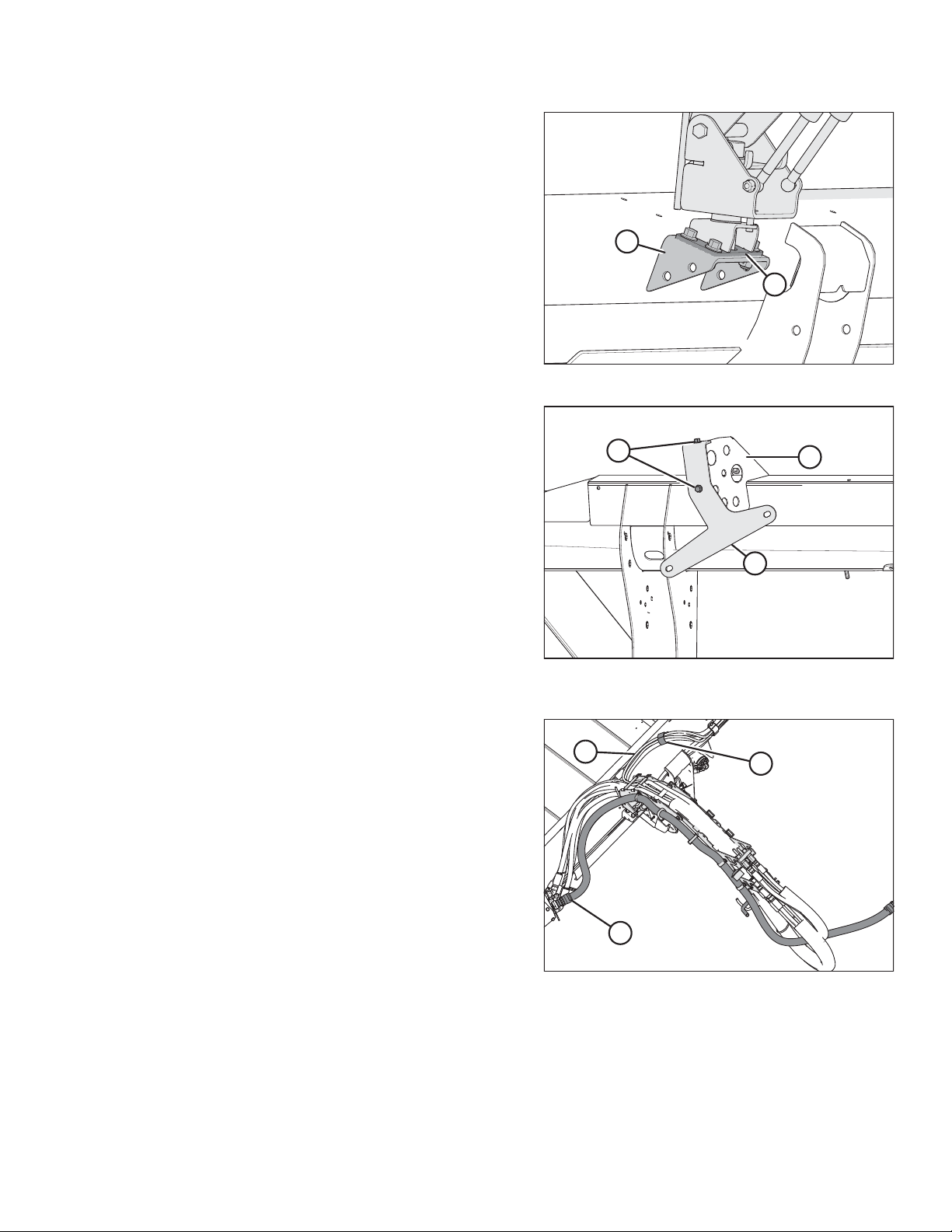
13. Secure the plate support (A) to the frame channel (B) using
the four bolts and nuts previously removed.
14. Remove sling from the hose management arm.
15. 7.6–10.6 m (25–35 ft.) Headers: Remove the two bolts (A)
and shipping support (B) from the coupler holder (C).
Discard shipping support (B) and reinstall the two bolts at
the same location on the coupler holder to secure the
hose cover.
Figure 3.10: Hose Management Arm Plate Support
Figure 3.11: Hose Management Arm Shipping Support
Bracket – 7.6–10.6 m (25–35 ft.) Headers
16. Connect harness connector (C) to the bulkhead on the
header’s coupler holder.
17. Cut the cable tie securing the hoses in position (A), and
secure the hoses with the strap (B) bolted on the frame.
IMPORTANT:
Note the routing of the hoses in the hose management arm
field position shown at right.
Figure 3.12: Hose Management Arm Hose Routing
(Top View)
214778 21 Revision A
Page 28
1015587
A
B
1015593
A
B
C
D
ATTACHING HEADER TO WINDROWER
3.2 Attaching Draper Header Supports
WARNING
To avoid bodily injury or death from unexpected startup of the machine, always stop the engine and remove the key
from the ignition before leaving the operator’s seat for any reason.
1. Retrieve header draper supports removed from shipping supports in Step 1, page 13.
2. Remove hairpin and clevis pin (B) from the draper header
support (A).
3. Position the draper header support (B) on lift linkage (A),
and reinstall clevis pin (C).
NOTE:
To avoid pin snagging the windrow, install the clevis pin on
the outboard side of the draper header support.
4. Secure clevis pin (C) with hairpin (D).
5. Repeat for opposite lift linkage.
Figure 3.13: Draper Header Support
Figure 3.14: Draper Header Support
214778 22 Revision A
Page 29
1016889
A
B
1000754
A
B
1015853
ATTACHING HEADER TO WINDROWER
3.3 Connecting Center-Link
WARNING
To avoid bodily injury or death from unexpected startup of the machine, always stop the engine and remove the key
from the ignition before leaving the operator’s seat for any reason.
1. Stop the engine and remove the key.
2. Hydraulic Center-Link without Self-Alignment: Relocate
pin (A) in frame linkage as required to raise the centerlink (B) until the hook is above the attachment pin on the
header.
IMPORTANT:
If the center-link is too low, it may contact the header as
the windrower approaches the header for hookup.
3. Remove hairpin (A) from pin (B), and remove pin (B) from
header leg. Repeat on the opposite header leg.
CAUTION
Check to be sure all bystanders have cleared the area.
4. Start engine.
CAUTION
When lowering header lift legs without a header or weight box
attached to the windrower, ensure the float springs tension is
fully released to prevent damage to the header lift linkages.
NOTE:
If not prompted by the Harvest Performance Tracker (HPT)
display to remove float, remove float manually by doing the
following:
Figure 3.15: Center-Link without Self-Alignment
Figure 3.16: Header Leg
214778 23 Revision A
Figure 3.17: Header Float Springs
Page 30
1015851
A
B
1019607
A
1018911
A
B
C
D
E
F
ATTACHING HEADER TO WINDROWER
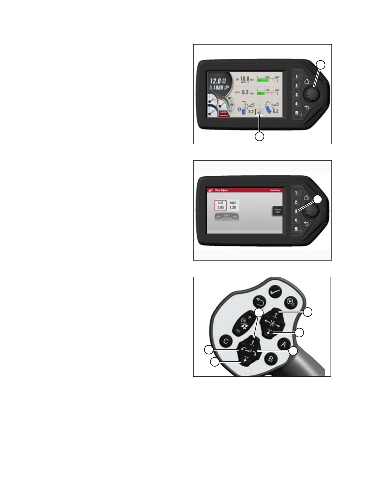
5. In the windrower cab, press scroll knob (A) on HPT to
display the QuickMenu system.
6. Rotate scroll knob (A) to highlight the HEADER FLOAT
symbol (B), and press scroll knob to select.
7. On Float Adjust page, press soft key 3 (A) to remove float.
Figure 3.18: HPT Display
8. Self-Aligning Hydraulic Center-Link:
a. Press HEADER DOWN switch on the ground speed lever
(GSL) to fully retract header lift cylinders.
b. Press REEL UP switch on the GSL to raise the center-link
until the hook is above the attachment pin on the header.
IMPORTANT:
If the center-link is too low, it may contact the header as the
windrower approaches the header for hookup.
Figure 3.19: HPT Display
Figure 3.20: GSL Switches
A - Reel Down B - Reel Up
C - Header Tilt Down D - Header Tilt Up
E - Header Down F - Header Up
214778 24 Revision A
Page 31

1015796
A
B
1016903
A
B
C
ATTACHING HEADER TO WINDROWER
9. Drive the windrower slowly forward until the draper header
supports (A) enter the header legs (B). Continue driving
slowly forward until lift linkages contact the support plates
in the header legs and the header nudges forward.
10. Ensure that lift linkages are properly engaged in header legs
and are contacting the support plates.
11. Self-Aligning Hydraulic Center-Link:
a. Adjust position of the center-link cylinder (A) with the
switches on the GSL until hook (B) is above the header
attachment pin.
IMPORTANT:
Hook release (C) must be down to enable self-locking
mechanism.
Figure 3.21: Header Leg and Draper Header Support
b. If the hook release (C) is open (up), stop the engine and
remove the ignition key. Manually push the hook
release (C) down after the hook engages the header pin.
c. Lower center-link (A) onto the header with REEL DOWN
switch on the GSL until the center-link locks into position
and the hook release (C) is down.
d. Check that center-link is locked onto header by pressing the
REEL UP switch on the GSL.
Figure 3.22: Hydraulic Center-Link
214778 25 Revision A
Page 32

1016901
A
B
1014786
A
1016103
A
ATTACHING HEADER TO WINDROWER
12. Hydraulic Center-Link without Self-Alignment:
a. Press HEADER TILT UP or HEADER TILT DOWN cylinder
switches on the GSL to extend or retract center-link cylinder
until the hook is aligned with the header attachment pin.
b. Stop the engine and remove the key.
c. Push down on rod end of link cylinder (B) until hook
engages and locks onto header pin.
IMPORTANT:
Hook release must be down to enable self-locking
mechanism. If the hook release is open (up), manually push
it down after hook engages pin.
d. Check that center-link (A) is locked onto header by pulling
upward on rod end (B) of cylinder.
CAUTION
Check to be sure all bystanders have cleared the area.
e. Start engine.
13. Press the HEADER UP switch (A) to raise header to
maximum height.
14. Stop the engine and remove the key.
15. Engage safety prop on the windrower’s lift cylinder as
follows:
Figure 3.23: Hydraulic Center-Link
Figure 3.24: GSL
a. Pull lever (A) and rotate toward header to release, and
lower safety prop onto cylinder.
b. Repeat for opposite lift cylinder.
IMPORTANT:
Ensure the safety props engage over the cylinder piston rods. If
safety prop does not engage properly, raise header until prop fits
over the rod.
Figure 3.25: Cylinder Safety Prop
214778 26 Revision A
Page 33

1000771
A
B
C
D
1014791
A
1014802
A
ATTACHING HEADER TO WINDROWER
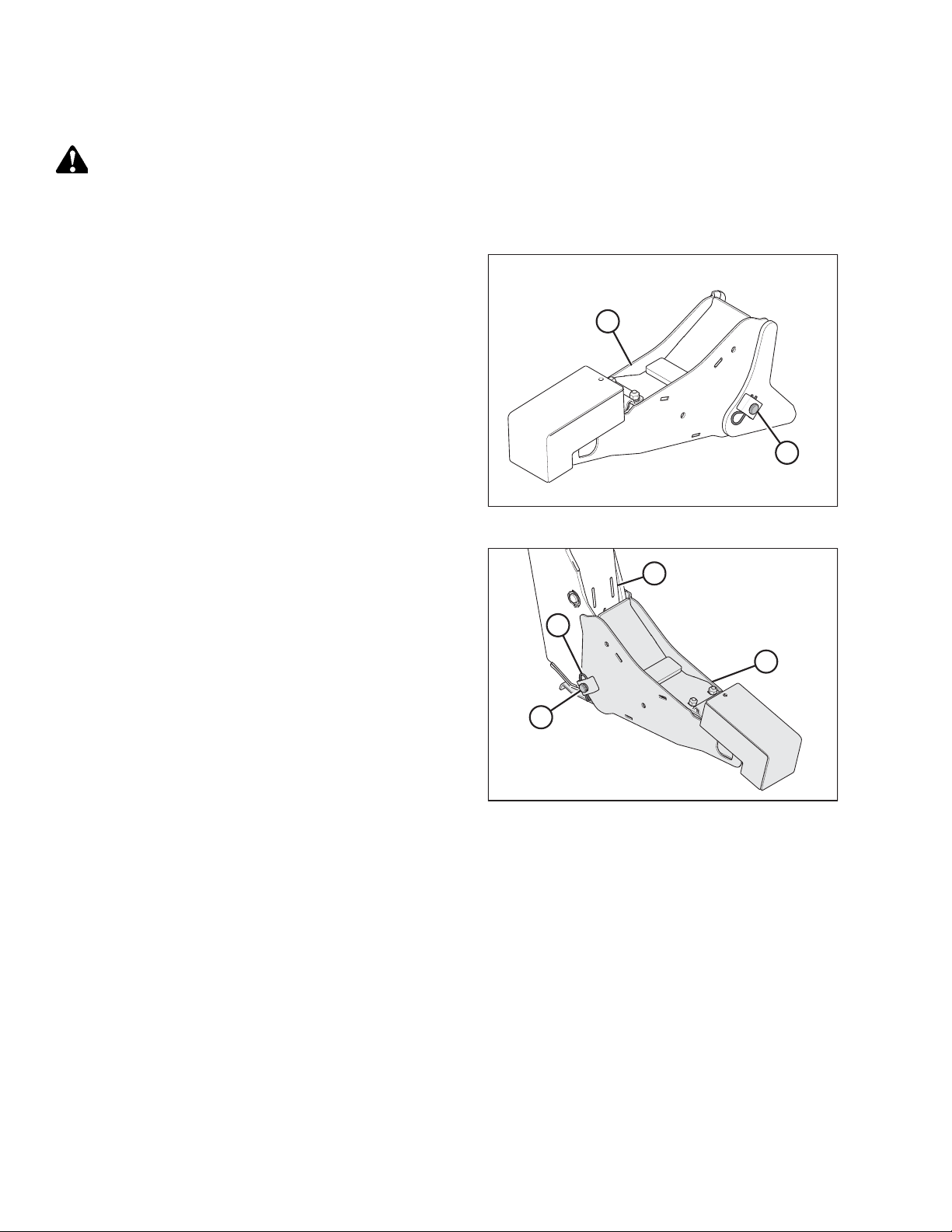
16. Install pin (B) through the header leg (engaging U-bracket in
draper header support) on both sides and secure with a
hairpin (A).
17. Raise header stand (D) to storage position by pulling spring
pin (C) and lifting stand into uppermost position. Release
spring pin.
18. Disengage safety prop by turning lever (A) downward to
raise safety prop until lever locks into vertical position.
NOTE:
If safety prop will not disengage, raise header slightly.
19. Repeat for opposite side.
Figure 3.26: Header Leg
CAUTION
Check to be sure all bystanders have cleared the area.
20. Start engine and press HEADER DOWN switch (A) on GSL to
fully lower header.
21. Stop the engine and remove the key.
Figure 3.27: Cylinder Safety Prop
Figure 3.28: GSL
214778 27 Revision A
Page 34

1024218
A
1015479
A
B
1015686
A
C
B
ATTACHING HEADER TO WINDROWER
3.4 Connecting Hydraulics
IMPORTANT:
To prevent contamination of the hydraulic system, use a clean rag to remove dirt and moisture from all (fixed and
movable) hydraulic couplers.
1. Move arm (A) toward left cab-forward side of windrower.
2. Remove all remaining ties and shipping wire from hose
management arm.
Figure 3.29: Hydraulic Hose Management Arm
3. Ensure cab door is closed on the left cab-forward side of
the windrower.
4. Push latch (B), and pull platform (A) toward walking beam
until it stops and latch engages.
5. Connect hydraulic hose management arm (A) to windrower
by securing the ball joint (B) on arm into the latch
support (C) on windrower leg.
Figure 3.30: Platform
Figure 3.31: Hydraulic Hose Management Arm
214778 28 Revision A
Page 35

1020151
A
B
C
D
E
F
1020152
A
B
C
D
1015479
A
B
ATTACHING HEADER TO WINDROWER
6. Retrieve draper drive and reel control multicoupler (A) from
hose management arm.
7. Push knob (B) on hydraulic receptacle and pull handle (C)
fully away from windrower.
8. Open cover (D) and position coupler onto receptacle. Align
pins in coupler with slots in handle (C) and push handle
toward windrower so that coupler locks onto receptacle
and knob (B) snaps out.
9. Remove cover from electrical connector (E), push electrical
connector onto receptacle, and secure by turning collar on
electrical connector clockwise.
10. Remove hose quick-disconnect (F) from storage location
and connect to receptacle on frame.
NOTE:
Hose quick-disconnect (F) is only present on M1240
machines configured for draper headers and on M1170
machines configured for rotary disc headers.
11. Retrieve knife and reel drive multicoupler (A) from hose
management arm.
12. Push knob (B) on hydraulic receptacle and pull handle (C)
fully away from windrower.
13. Open cover (D) and position coupler onto receptacle. Align
pins in coupler with slots in handle (C) and push handle
toward windrower so that coupler locks onto receptacle
and knob (B) snaps out.
14. Push latch (B) to unlock platform (A).
Figure 3.32: Draper/Reel Multicoupler
Figure 3.33: Knife/Reel Drive Multicoupler
15. Push the platform towards the cab until it stops and latch
engages.
Figure 3.34: Platform
214778 29 Revision A
Page 36

1015750
ATTACHING HEADER TO WINDROWER
16. Ensure hydraulic hose routing is as straight as possible and
avoids potential rub/wear points.
Figure 3.35: Hydraulic Multicouplers and Hose
Routing
214778 30 Revision A
Page 37

Chapter 4: Assembling the Header
1023878
B
A
1023569
A
B
Perform all the procedures in this chapter in the order in which they are listed.
4.1 Positioning Transport Lights
Transport lights are located on each outboard reel arm. They are shipped in an inverted position on the inboard sides of
the reel arms.
1. Remove lock nut (B) holding right light assembly (A) to reel
arm and remove light assembly. Retain lock nut.
Figure 4.1: Right Light Assembly in Shipping Position
2. Position the right light assembly (A) perpendicular to right
reel arm and attach using retained lock nut (B).
NOTE:
Light assembly should rotate with normal hand force yet
maintain its position.
Figure 4.2: Right Transport Light
214778 31 Revision A
Page 38

1023912
A
B
1023919
A
B
ASSEMBLING THE HEADER
3. Remove lock nut (A) holding left light assembly (B) to reel
arm and remove light assembly. Retain lock nut.
4. Position the left light assembly (B) perpendicular to left reel
arm and attach using retained lock nut (A).
NOTE:
Light assembly should rotate with normal hand force yet
maintain its position.
Figure 4.3: Left Light Assembly in Shipping Position
Figure 4.4: Left Transport Light
214778 32 Revision A
Page 39

1024660
1
2
A
A
A
1014042
A
ASSEMBLING THE HEADER
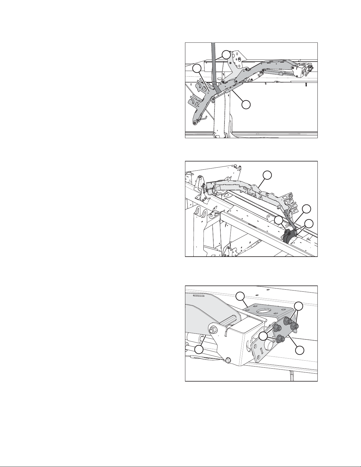
4.2 Attaching Reel Lift Cylinders
CAUTION
Bolts (A) (with tags) on reel arms keep the reel from sliding
forward. Ensure fore-aft cylinders are attached before
removing bolts.
Figure 4.5: Right Reel Arm
1 - Single Reel 2 - Double Reel
Figure 4.6: Left Reel Arm
214778 33 Revision A
Page 40

1008126
A
B
1006382
A
1001081
A
ASSEMBLING THE HEADER
NOTE:
Some parts removed from illustration for clarity.
1. Position sling (A) around the reel tube (B) close to the
outboard end of reel and attach sling to a forklift or
equivalent lifting device.
2. Remove shipping wire/banding from the reel lift cylinder.
3. Lift reel and remove two top bolts (A) on outboard reel arm
supports. Repeat for opposite side.
Figure 4.7: Reel Tube
4. Double-reel headers only: Lift reel and remove two top
bolts (A) on center reel arm to allow the center reel arm
to move.
Figure 4.8: Outboard Reel Arm Support
Figure 4.9: Center Reel Arm – Double Reel Only
214778 34 Revision A
Page 41

1008127
A
B
1006381
A
B
ASSEMBLING THE HEADER
5. Lift reel and remove pins from the endsheet and the
reel arm.
6. Align the reel lift cylinder mounting holes until they line up
with the lug on endsheet and the hole in the reel arm.
7. Secure cylinder to endsheet and reel arm with pins
as shown.
• Insert cotter pin (A) OUTBOARD at reel arm
• Insert cotter pin (B) INBOARD at endsheet
8. Move reel safety props (A) to engaged position (B) at
outer arm.
Figure 4.10: Right Reel Lift Cylinder
Figure 4.11: Reel Safety Props
214778 35 Revision A
Page 42

1006380
A
1019106
A
B
1008131
A
ASSEMBLING THE HEADER
9. For double reel only:
a. Position sling (A) around the reel tube near the reel center
support arm.
b. Lift reel to gain access to the center lift cylinder.
c. Remove shipping wire and banding from center reel lift
cylinder.
10. For double reel only:
a. Remove 3/4 in. socket head bolt and 5/8 in. nut from
cylinder rod end. Retain hardware.
b. Attach rod end of cylinder (B) to reel arm with socket head
bolt and nut (A). Access hardware through holes in reel arm
braces.
Figure 4.12: Lifting the Reel – Double Reel Only
c. Torque bolt and nut (A) to 54–61 Nm (40–45 lbf·ft).
d. Remove pin at barrel end of cylinder.
e. Adjust reel height so pin can be installed at barrel end of
cylinder and mounting structure.
11. Reposition the sling (A) around reel tube near the opposite
outboard reel arm.
12. Remove shipping wire and banding from the reel lift
cylinder.
Figure 4.13: Reel Arm Braces
Figure 4.14: Outboard Reel Arm
214778 36 Revision A
Page 43

1008132
A
B
1006381
A
B
ASSEMBLING THE HEADER
13. Lift reel and remove pins from the endsheet (B) and the
reel arm (A).
14. Align the reel lift cylinder mounting holes until they line up
with the lug on endsheet and the hole in the reel arm.
15. Secure cylinder to endsheet and reel arm with pins
as shown.
• Insert cotter pin (A) OUTBOARD at reel arm
• Insert cotter pin (B) INBOARD at endsheet
16. Move the reel safety props (A) to engaged position (B).
Figure 4.15: Left Reel Lift Cylinder
Figure 4.16: Reel Safety Prop
214778 37 Revision A
Page 44

1001080
A
B
1006378
A
ASSEMBLING THE HEADER
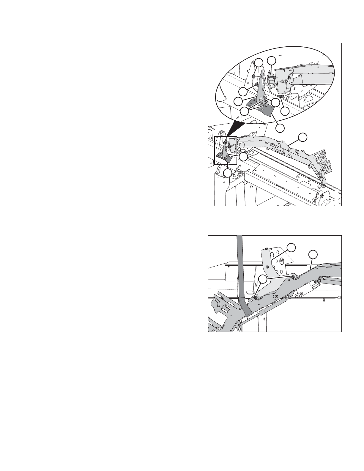
17. Double reel only: Remove the remaining bolt (A),
disengage center reel arm shipping support (B) from
cutterbar, and remove shipping support.
18. Remove bolts (A) from reel arm support at endsheet and
remove support. Repeat at other side.
Figure 4.17: Center Reel Arm Shipping Support
Figure 4.18: Outboard Reel Arm Supports
214778 38 Revision A
Page 45

1024661
1
2
A
A
A
1014042
A
ASSEMBLING THE HEADER
19. Remove brace bolts and tags (A) locking the reel fore-aft
position at outer reel arms.
NOTE:
Do NOT use hydraulic pressure to move fore-aft cylinder to
aid in removing brace bolts. Cylinder damage may occur.
Figure 4.19: Right Reel Arm
1 - Single Reel 2 - Double Reel
Figure 4.20: Left Reel Arm
214778 39 Revision A
Page 46

1013700
A
B
A
ASSEMBLING THE HEADER
20. Double reel only: Remove the remaining three bolts (A)
locking the reel fore-aft position at the center reel arm and
remove shipping channel (B).
Figure 4.21: Center Reel Arm Shipping Channel –
Double-Reel Only
214778 40 Revision A
Page 47

1017008
A
1017010
A
B
C
1017011
A
B
C
D
E
ASSEMBLING THE HEADER
4.3 Installing Disc Segments of Outboard Reel Endshields
To meet the trucking load regulations for the maximum load
width and height, two disc segments of the reel endshields (A)
may have been removed from the right reel (tail end) and left
reel (cam end). Check if reel endshields are completely installed.
If not, install the two disc segments as follows:
Figure 4.22: Partially Installed Reel Endshield – Cam
End Shown, Tail End Similar
1. Retrieve the bag of hardware removed from the center
draper support.
2. Remove the two bolts (A) securing the disc segments to
support tabs. Retain for reinstallation later.
3. Engage slots on disc segment (B) on endshield support
tabs (C).
4. Secure the other end of the disc segment to support using
the bolt (A) that was removed earlier.
5. Position last disc segment (B) in front of disc segment (C)
and behind disc segment (D), engage endshield support
tabs through all disc segments, and secure with two
bolts (E).
NOTE:
It may be necessary to loosen hardware and use a pry tool
to secure the last disc segment in place.
6. Repeat procedure at the opposite side.
Figure 4.23: Reel Endshield
Figure 4.24: Reel Endshield
214778 41 Revision A
Page 48

1026970
A
B
1026960
A
B
C
1008160
A
ASSEMBLING THE HEADER
4.4 Attaching Cam Arms
To attach the reel cam arms, follow these steps:
NOTE:
On nine-bat reel headers, one cam arm assembly was removed and secured to the tine tube for shipping purposes.
1. Nine-bat reel headers: Remove shipping wire (A) and foam,
and remove cam arm assembly (B) from the tine tube.
Figure 4.25: Cam Arm in Shipping Position
2. Nine-bat reel headers: Install cam arm assembly (A) onto
arm (B), and secure with 1/2 in. smooth face lock nut (C).
Torque to 75 Nm (55 lbf·ft).
3. Rotate the reel manually until the tine bars with
disconnected cam links are accessible.
4. Remove shipping wire (A) (if not already removed).
Figure 4.26: Cam Arm Assembly
Figure 4.27: Disconnected Cam Links and
Shipping Wire
214778 42 Revision A
Page 49

1009261
A
1024826
A
B
C
D
B
ASSEMBLING THE HEADER
5. Remove bag of hardware (A) from tine bar. It contains
hardware for cam links and endshields.
6. Rotate tine bar crank (A) and position link (B) so
attachment holes in bar crank are aligned with hole in link.
7. Install bolt (C) in link and position shim (D) on bolt so that
shim is between link and tine bar crank.
NOTE:
Bolts are precoated with Loctite
®
, so no further locking
method is required.
Figure 4.28: Hardware Bag Right Reel
8. Realign link (B) and tine bar crank (A) and thread in bolt (C).
9. Repeat for remaining tine bars and torque bolts to 165 Nm
(120 lbf·ft).
Figure 4.29: Bar Crank Attachment Holes and Link
Alignment
214778 43 Revision A
Page 50

1024477
A
B
C
D
1008371
A
B
C
1007923
A
B
ASSEMBLING THE HEADER
4.5 Installing Crop Dividers
One crop and two divider rods are stored on the right inboard side of the endsheet; the other crop divider is stored on the
left inboard side of the endsheet.
1. Loosen the bolt at location (A) on the lock tab securing the
divider rods (B) to the storage bracket (C).
2. Remove divider rods (B) from the storage bracket (C) and
pull away from the lower divider rod support (D). Set aside
for installation later.
3. Return lock tab to its original position and tighten bolt at
location (A).
Figure 4.30: Divider Rods on Endsheet
4. Support the crop divider, remove shipping wire (A) at front
end, and remove bolt (B).
5. Remove bolt and washer (C).
6. Position crop divider as shown and insert lugs (A) into
slots (B) in endsheet.
Figure 4.31: Crop Divider on Endsheet
Figure 4.32: Crop Divider Lugs and Endsheet Slots
214778 44 Revision A
Page 51

1007922
A
B
1016511
A
B
1007921
A
ASSEMBLING THE HEADER
7. Lift forward end of divider up to endsheet and install
washer (A) and bolt (B).
8. Position divider rod (B) on tip of crop divider as shown and
tighten bolt (A).
Figure 4.33: Installing Divider
Figure 4.34: Divider Rod on Crop Divider
9. Check that divider does NOT move laterally. Adjust bolts (A)
as required to tighten divider and remove lateral play when
pulling at divider tip.
10. Repeat Step 4, page 44 to Step 9, page 45 on the left side
of the header.
Figure 4.35: Adjustment Hardware
214778 45 Revision A
Page 52

ASSEMBLING THE HEADER
4.6 Installing Options
Retrieve the kits supplied as options with the header, and install them according to the instructions supplied with each kit.
214778 46 Revision A
Page 53

ASSEMBLING THE HEADER
4.7 Adding Ballast
M1 Series windrowers use counterweight kits to add ballast. The counterweights are used to improve a windrower’s
balance while operating with a header. Each kit comes with eight counterweights totaling 163 kg (360 lb.) and required
hardware. The M1 Series windrowers will hold a maximum of 24 counterweights totaling 490 kg (1080 lb.).
Table 4.1, page 47 lists the number of counterweight kits required for each D1XL Series and D125X header configuration.
Install them according to the instructions supplied with each kit.
Table 4.1 Available Ballast Kits for Different Header Types and Configurations
Header Type
D115X
D120X
D125X
D130XL
D130XL
D135XL
D135XL
D135XL
D135XL
Description
4.6 m (15 ft.) single reel,
double knife, timed
6.1 m (20 ft.) single reel,
double knife, timed
7.6 m (25 ft.) single reel,
double knife, timed
9.1 m (30 ft.) single reel,
double knife, timed
9.1 m (30 ft.) single reel,
double knife, timed
10.6 m (35 ft.) single reel,
double knife, untimed
10.6 m (35 ft.) single reel,
double knife, untimed
10.6 m (35 ft.) single reel,
double knife, untimed
10.6 m (35 ft.) double reel,
double knife, untimed
Header Configuration
Base
Base
Base
Transport
Transport,
Upper cross auger,
Vertical knives
Base
Transport
Transport,
Upper cross auger,
Vertical knives
Base
Initial Rear
Ballast Kit
––
––
––
––
––
––
––
––
––
Additional Rear
Ballast Kits
D135XL
D135XL
D140XL
D140XL
D140XL
D145XL
214778 47 Revision A
10.6 m (35 ft.) double reel,
double knife, untimed
10.6 m (35 ft.) double reel,
double knife, untimed
12.2 m (40 ft.) double reel,
double knife, untimed
12.2 m (40 ft.) double reel,
double knife, untimed
12.2 m (40 ft.) double reel,
double knife, untimed
13.7 m (45 ft.) double reel,
double knife, untimed
Transport
Transport,
Upper cross auger,
Vertical knives
Base
Transport
Transport,
Upper cross auger,
Vertical knives
Base
––
––
––
––
1
1
–
–
Page 54

ASSEMBLING THE HEADER
Table 4.1 Available Ballast Kits for Different Header Types and Configurations (continued)
Header Type
D145XL
D145XL
Description
13.7 m (45 ft.) double reel,
double knife, untimed
13.7 m (45 ft.) double reel,
double knife, untimed
Header Configuration
Initial Rear
Ballast Kit
Transport 1 1
Transport,
Upper cross auger,
11
Vertical knives
Additional Rear
Ballast Kits
When the recommended fluid ballast has been added, proceed to 5 Performing Predelivery Checks, page 49.
214778 48 Revision A
Page 55

Chapter 5: Performing Predelivery Checks
This machine has been set at the factory and should not require further adjustments; however, the following checks will
ensure your machine provides maximum performance. If adjustments are necessary, follow the procedures in this chapter.
WARNING
To avoid bodily injury or death from unexpected startup of machine, always stop engine and remove key before
adjusting machine.
IMPORTANT:
To avoid machine damage, check that no shipping material has fallen into the machine.
1. Perform the final checks as listed on the Predelivery Checklist (yellow sheet attached to this instruction – Predelivery
Checklist, page 99) to ensure the machine is field-ready. Refer to the following pages for detailed instructions as
indicated on the Checklist. The completed Checklist should be retained by either the Operator or the Dealer.
5.1 Checking Tire Pressure – Transport and Stabilizer Wheels
Check tire inflation pressure. If necessary, inflate tires according to the following table:
Table 5.1 Tire Inflation Pressure
Tire Size
Goodyear Wrangler RT/S 205/75 R15
Carlisle and Titan
IMPORTANT:
Do NOT exceed maximum pressure specified on tire sidewall.
ST205/75 R15
Pressure
276 kPa (40 psi)
448 kPa (65 psi)
214778 49 Revision A
Page 56

1001277
2
3
4
5
6
1
PERFORMING PREDELIVERY CHECKS
5.2 Checking Wheel Bolt Torque
Perform the following procedure to ensure that transport and stabilizer wheel bolts are correctly torqued:
1. Check wheel bolt torque is 110–120 Nm (80–90 lbf·ft) and
adjust as necessary. Refer to bolt tightening sequence
illustration.
Figure 5.1: Sequence for Tightening Bolts
214778 50 Revision A
Page 57

1024277
A
B
1024800
A
B
PERFORMING PREDELIVERY CHECKS
5.3 Checking Knife Drive Box
Single-knife headers have one knife-drive box and double-knife headers have two knife-drive boxes. To access the knife
drive box(es), endshield(s) must be fully opened.
WARNING
To avoid bodily injury or death from unexpected startup of machine, always stop engine and remove key before making
adjustments to machine.
1. Press down on the latch in the opening (A) on the inboard
side of the endsheet.
2. Pull endshield open using handle depression (B).
3. Swivel the endshield toward the back of the header and use
the safety latch (B) to secure the endshield support tube (A)
to the endsheet.
Figure 5.2: Endshield Latch Access
Figure 5.3: Left Endshield Support Tube
214778 51 Revision A
Page 58

1020658
A
B
D
E
C
PERFORMING PREDELIVERY CHECKS
IMPORTANT:
The knife drive box breather is shipped in position (A)
(forward) to prevent oil loss during transport. The breather
MUST be repositioned to location (B) to prevent oil loss
during normal operation. Failure to do so can result in
damage to the knife drive box.
4. Check position of plug (A) and breather (B) at knife drive
box. Position MUST be as shown.
5. Remove breather (B) and check oil level. The oil level
should be between the bottom edge (C) of the lower
hole (D) and the bottom (E) of the breather.
NOTE:
Check oil level with top of knife drive box horizontal and
with the breather (B) screwed in.
6. Reinstall breather and tighten.
Figure 5.4: Knife Drive Box
214778 52 Revision A
Page 59

1022180
A
B
C
1002468
A
B
C
PERFORMING PREDELIVERY CHECKS
5.4 Checking and Adjusting Knife Drive Belt Tension
Proceed to the section that applies to the header’s knife drive configuration:
• 5.4.1 Checking and Tensioning, page 53
• 5.4.2 Tensioning Timed Knife Drive Belts, page 54
• 5.4.3 Tensioning Timed Knife Drive V-Belts, page 56
Single-knife headers have one knife-drive belt and double-knife headers have two knife-drive belts.
5.4.1 Checking and Tensioning
WARNING
To avoid bodily injury or death from unexpected startup of machine, always stop engine and remove key before making
adjustments to machine.
IMPORTANT:
To prolong the belt and drive life, do NOT overtighten the belt.
1. Open the left endshield.
NOTE:
Belt guide removed for illustration purposes.
2. Loosen the two bolts (A) securing the motor assembly to
the header endsheet.
3. Check drive belt tension. A properly tensioned drive belt (C)
should deflect 24–28 mm (15/16–1-1/8 in.) when 133 N
(30 lbf) of force is applied at the midspan. If the belt needs
to be tensioned, turn the adjuster bolt (B) clockwise to
move the drive motor until proper tension is set.
4. Ensure the clearance between belt (A) and belt guide (B) is
1 mm (1/16 in.).
5. Loosen the three bolts (C), and adjust the position of
guide (B) as required.
6. Tighten the three bolts (C).
7. Close the endshield.
8. Double-knife headers only: Repeat procedure on the other
side of the header.
Figure 5.5: Knife Drive
214778 53 Revision A
Figure 5.6: Knife Drive
Page 60

1019546
A
B
1020049
A
B
C
PERFORMING PREDELIVERY CHECKS
5.4.2 Tensioning Timed Knife Drive Belts
The procedure for tensioning timed knife drive belts is the same for both sides of the header. The illustrations shown are
for the left side —the right side is opposite.
IMPORTANT:
To prolong belt and drive life, do NOT overtighten belt.
IMPORTANT:
Do NOT use the adjuster bolt at the drive pulley to adjust timing belt tension.
1. Open the endshield.
2. Loosen two nuts (A) enough to allow the idler pulleys (B)
to pivot.
3. Thread flange nut (C) down adjuster bolt (B) to push the
bracket (A) up.
NOTE:
Tension is checked at midspan of the belts. The belts should
deflect 20 mm (3/4 in.) with 89 N (20 lbf) of force applied.
Figure 5.7: Left Knife Drive
Figure 5.8: Left Knife Drive
214778 54 Revision A
Page 61

1019546
A
B
1020051
B
A
1019643
A
B
C
D
E
F
PERFORMING PREDELIVERY CHECKS
4. Tighten nuts (A) on idler pulleys (B) to 217 Nm (160 lbf·ft).
5. Tighten jam nut (A) to prevent loosening of the adjuster
bolt (B).
Figure 5.9: Left Knife Drive
6. Ensure there is a clearance of 2.5–3.5 mm (1/8 in.) between
the lower belt (A) and lower guide (B).
7. If necessary, loosen the three bolts (C) and adjust lower
guide (B) as required. Tighten bolts.
8. Check that upper belt (D) and upper guide (E) have a
clearance of 1.5–2.5 mm (1/16–1/8 in.). If necessary, loosen
the two bolts (F) and adjust as required. Tighten the bolts.
9. Repeat procedure for other side of header.
Figure 5.10: Left Knife Drive
Figure 5.11: Left Knife Drive
214778 55 Revision A
Page 62

1016806
A
B
C
PERFORMING PREDELIVERY CHECKS
5.4.3 Tensioning Timed Knife Drive V-Belts
1. Loosen the two bolts (A).
2. Turn drawbolt (B) clockwise to tighten or counterclockwise
to loosen belts (C) tension.
NOTE:
Tension is checked at midspan of the belts. The belts should
deflect 4 mm (5/32 in.) with 52–77 N (12–17 lbf) of force
applied to each belt.
3. Tighten bolts (A).
Figure 5.12: Knife Drive V-belts
214778 56 Revision A
Page 63

1019035
A
1026077
B
C
B
A
PERFORMING PREDELIVERY CHECKS
5.5 Centering the Reel
Refer to the topic for header type:
• 5.5.1 Centering Double Reels, page 57
• 5.5.2 Centering Single Reel, page 58
5.5.1 Centering Double Reels
WARNING
To avoid bodily injury or death from unexpected startup of machine, always stop engine and remove key before
adjusting machine.
1. Measure clearances at locations (A) between reels and both
endsheets. The clearances should be the same if the reels
are centered. If the reels are not centered, proceed to
Step 2, page 57.
Figure 5.13: Double Reel Measurement Locations
2. Loosen bolts (A) on each brace (B) located on both sides of
the reel center support arm (C).
3. Move the forward end of the reel center support arm (C)
laterally as required, to center both reels.
4. Tighten bolts (A) and torque to 382 Nm (282 lbf∙ft).
Figure 5.14: Reel Center Support Arm
214778 57 Revision A
Page 64

1001595
A
1016444
A
B
C
PERFORMING PREDELIVERY CHECKS
5.5.2 Centering Single Reel
WARNING
To avoid bodily injury or death from unexpected startup of machine, always stop engine and remove key before
adjusting machine.
1. Measure the clearance at locations (A) between the reel
and endsheets. The clearances should be the same if the
reel is centered.
• If the reel is not centered, proceed to Step 2, page 58.
• If the reel is centered, proceed to 5.6 Adjusting Draper
Tension, page 59.
Figure 5.15: Single Reel Measurement Locations
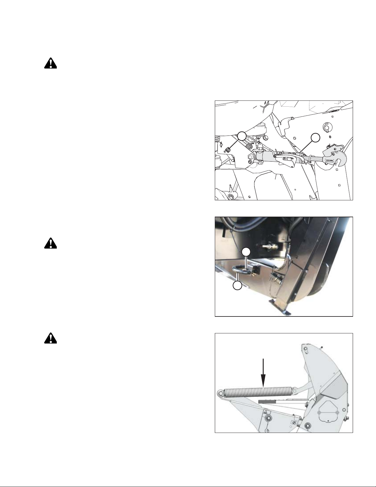
2. Loosen bolt (A) on the brace (B) at both ends of the reel.
3. Move the forward end of the reel support arm (C) laterally
as required, to center the reel.
4. Tighten bolt (A) and torque to 359 Nm (265 lbf∙ft). Repeat
at opposite side.
Figure 5.16: Reel Support Arm
214778 58 Revision A
Page 65

1008647
A
1008417
A
1008418
A
B
PERFORMING PREDELIVERY CHECKS
5.6 Adjusting Draper Tension
WARNING
To avoid bodily injury or death from unexpected start-up or fall of raised machine, always stop engine, remove key, and
engage safety props before going under machine for any reason.
1. Ensure the white indicator bar (A) is at the halfway point in
the window.
WARNING
Check to be sure all bystanders have cleared the area.
2. Start the engine and fully raise the header.
3. Shut down the windrower and remove the key from the
ignition.
4. Engage the header safety props.
Figure 5.17: Left Side Tension Adjuster Shown – Right
Side Opposite
5. Ensure the draper guide (the rubber track on the underside
of the draper) is properly engaged in the groove (A) on the
drive roller.
6. Ensure the idler roller (A) is between the draper guides (B).
Figure 5.18: Drive Roller
214778 59 Revision A
Figure 5.19: Idler Roller
Page 66

1021001
A
B
C
D
E
PERFORMING PREDELIVERY CHECKS
IMPORTANT:
Do NOT adjust nut (C). This nut is used for draper
alignment only.
7. To loosen draper tension, turn adjuster bolt (A)
counterclockwise. The white indicator bar (B) will move
outboard in the direction of arrow (D) to indicate that the
draper is loosening. Loosen until the white indicator bar is
at the halfway point in the window.
8. To tighten draper tension, turn adjuster bolt (A) clockwise.
The white indicator bar (B) will move inboard in the
direction of arrow (E) to indicate that the draper is
tightening. Tighten until the white indicator bar is at the
halfway point in the window.
IMPORTANT:
To avoid premature failure of the draper, draper rollers,
and/or tightener components, do NOT operate if the white
bar is not visible.
IMPORTANT:
To prevent scooping dirt, ensure the draper is tight enough
that it does not sag below the point where the cutterbar
contacts the ground.
Figure 5.20: Left Side Tension Adjuster Shown – Right
Side Opposite
214778 60 Revision A
Page 67

1014214
A
B
1014218
A
1009729
A
B
PERFORMING PREDELIVERY CHECKS
5.7 Checking and Adjusting Draper Seal
Maintain the deck height such that the draper runs just below the cutterbar.
IMPORTANT:
New factory-installed drapers are pressure and heat checked at
the factory. The gap between the draper (A) and cutterbar (B) is
set to 1–3 mm (1/32–1/8 in.). To prevent material from entering
the drapers and cutterbar, you may need to decrease the deck
clearance to 0 mm (0 in.) after an initial break-in period of
approximately 50 hours.
1. Check deck height. Draper (A) should run just below
cutterbar (B) with a gap of 1–3 mm (1/32–1/8 in.) between
the top of deck front track and cutterbar.
• If deck height is acceptable, skip the remaining steps
and proceed to 5.8 Checking and Adjusting Skid Shoe
Settings, page 63.
• If deck height is NOT acceptable, adjust seal as
described in the following steps:
NOTE:
Take measurement at deck supports (A) with the header in
working position. There are between two and five supports
per deck depending on header size.
Figure 5.21: Draper/Cutterbar Gap
2. Loosen tension on drapers. For instructions, refer to 5.6
Adjusting Draper Tension, page 59.
3. Lift draper (A) up at front edge past cutterbar (B).
Figure 5.22: Draper Deck Supports
Figure 5.23: Draper and Cutterbar
214778 61 Revision A
Page 68

1003841
A
B
C
PERFORMING PREDELIVERY CHECKS
4. Loosen two lock nuts (A) a half-turn on deck support (B).
NOTE:
Deck shown with draper removed.
5. Tap deck (C) to lower deck relative to supports and achieve
the recommended setting. Tap support (B) using a punch to
raise deck relative to supports.
6. Tighten deck support hardware (A).
7. Tension drapers. Refer to 5.6 Adjusting Draper Tension,
page 59.
Figure 5.24: Draper Deck Supports
214778 62 Revision A
Page 69

1007626
A
C
B
1007911
A
B
C
PERFORMING PREDELIVERY CHECKS
5.8 Checking and Adjusting Skid Shoe Settings
To check and adjust skid shoes, follow these steps:
WARNING
To avoid bodily injury or death from unexpected start-up or fall of raised machine, always stop engine, remove key, and
engage safety props before going under machine for any reason.
DANGER
Engage header safety props and reel props before working under header or reel.
1. Check the adjustment hole positions on the lugs (A) on
each skid shoe. They should be the same.
2. If necessary, adjust skid shoe as follows:
a. Remove lynch pin (B).
b. Hold shoe and remove pin (C) by disengaging frame and
then pulling away from shoe.
c. Raise or lower skid shoe to desired position using holes in
support as a guide.
d. Reinsert pin (C), engage in frame, and secure with lynch
pin (B).
e. Check that all skid shoes are adjusted to the same position.
Figure 5.25: Inner Skid Shoe
Figure 5.26: Outer Skid Shoe
214778 63 Revision A
Page 70

PERFORMING PREDELIVERY CHECKS
5.9 Leveling the Header
The windrower linkages are factory-set to provide the proper level for the header and should not normally require
adjustment.
1. If the header is not level, check the pressure of the windrower’s tires to ensure they are properly inflated (refer to
your windrower operator’s manual).
2. If the header is still not level, adjust the windrower linkages as required (refer to the appropriate section in the
windrower operator’s manual).
NOTE:
The float springs are NOT used to level the header.
214778 64 Revision A
Page 71

1005640
X
1019036
A
PERFORMING PREDELIVERY CHECKS
5.10 Measuring and Adjusting Reel Clearance to Cutterbar
The minimum clearance between the reel fingers and the cutterbar ensures that the reel fingers do not contact the
cutterbar during operation. The clearance is set at the factory, but some adjustment may be necessary before operation.
The finger to guard/cutterbar clearances with reels fully lowered are shown in Table 5.2, page 65.
Table 5.2 Finger to Guard/Cutterbar Clearance
Header Width
4.6 m (15 ft.)
6.1 m (20 ft.)
7.6 m (25 ft.)
9.1 m (30 ft.)
10.7 m (35 ft.)
12.2 m (40 ft.)
13.7 m (45 ft.)
(X) 3 mm (+/- 1/8 in.) at Reel Ends
Single Reel Double Reel
20 mm
(3/4 in.)
20 mm
(3/4 in.)
25 mm
(1 in.)
55 mm
(2-11/64 in.)
70 mm
(2-3/4 in.)
—
—
5.10.1 Measuring Reel Clearance
DANGER
—
—
—
25 mm
(1 in.)
25 mm
(1 in.)
25 mm
(1 in.)
25 mm
(1 in.)
Figure 5.27: Finger Clearance
To avoid bodily injury or death from unexpected start-up or fall of raised machine, always stop engine, remove key, and
engage safety props before going under header for any reason.
1. Park the header on level ground.
2. Set the fore-aft position to the middle position 5 on the
fore-aft position decal (A).
3. Lower the reel fully.
4. Shut down the engine and remove key from the ignition.
Figure 5.28: Fore-Aft Position
214778 65 Revision A
Page 72

1012625
X
C
B
1001595
A
1001596
A
PERFORMING PREDELIVERY CHECKS
5. Measure the clearance (X) at all possible points of contact
(between points [B] and [C] at the ends of each reel [A]) as
shown in Figure 5.30, page 66 and 5.31, page 66.
NOTE:
The reel is factory-set to provide more clearance at the
center of the reel than at the ends (frown) to compensate
for reel flexing.
NOTE:
When measuring reel clearance at the center of a doublereel header, measure the lowest reel.
6. Check all possible points of contact between points (B)
and (C). Depending on the reel fore-aft position, minimum
clearance can result at the guard tine, hold-down, or
cutterbar.
7. Adjust the reel if necessary. Refer to 5.10.2 Adjusting Reel
Clearance, page 67.
Figure 5.29: Reel Clearance
Figure 5.30: Single Reel Measurement Locations –
Two Places
Figure 5.31: Double Reel Measurement Locations –
Four Places
214778 66 Revision A
Page 73

1001329
A
B
1009601
A
B
C
PERFORMING PREDELIVERY CHECKS
5.10.2 Adjusting Reel Clearance
DANGER
To avoid bodily injury or death from unexpected start-up or fall of raised machine, always stop engine, remove key, and
engage safety props before going under header for any reason.
1. Shut down the engine, and remove the key from the
ignition.
2. Adjust outboard reel arm lift cylinders to set clearance at
outboard ends of reel as follows:
a. Loosen bolt (A).
b. Turn cylinder rod (B) out of clevis to raise reel and increase
clearance to cutterbar, or turn cylinder rod into clevis to
lower reel and decrease clearance.
c. Tighten bolt (A).
d. Repeat at opposite side.
Figure 5.32: Outside Reel Arm
3. For double reel: Adjust center arm lift cylinder stop (A) to
change clearance at inboard ends of reels as follows:
a. Loosen nut (B).
b. Turn nut (C) counterclockwise to raise reel and increase
clearance to cutterbar, or clockwise to lower reel and
decrease clearance.
c. Tighten nut (B).
Figure 5.33: Underside of Center Arm
4. Check measurements and, if necessary, repeat adjustment procedures.
5. Move reel back to ensure steel end fingers do not contact deflector shields.
6. If contact occurs, adjust reel upward to maintain clearance at all reel fore-aft positions. If contact cannot be avoided
after adjusting the reel, trim steel end fingers to obtain proper clearance.
7. Periodically check for evidence of contact during operation, and adjust clearance as required.
214778 67 Revision A
Page 74

1001672
X
1024273
B
A
PERFORMING PREDELIVERY CHECKS
5.11 Checking and Adjusting Endshields
Endshields are subject to expansion or contraction caused by large temperature variations. The position of the top pin and
lower latch can be adjusted to compensate for dimensional changes.
Checking the endshield:
1. Check gap (X) between front end of the shields and the
header frame and compare to the values in Table 5.3, page
68.
Table 5.3 Endshield Gap at Various Temperatures
Temperature in °C(°F)
7 (45)
18 (65)
29 (85)
41 (105)
Gap (X)
mm (in.)
13–18 (1/2–23/32)
10–15 (3/8–19/32)
7–12 (9/32–15/32)
4–9 (5/32–11/32)
2. If the endshield gap is correct, skip to the next procedure. If
adjustment is required, proceed to Step 1, page 68.
Opening the endshield:
1. To unlock the shield, push the release lever (A) located on
the backside of the endshield.
Figure 5.34: Gap between Endshield and
Header Frame
2. Pull endshield open using handle depression (B).
214778 68 Revision A
Figure 5.35: Left Endshield
Page 75

1024275
A
B
C
1012300
A
B
1025332
A
B
A
A
A
PERFORMING PREDELIVERY CHECKS
3. Pull endshield at handle depression (A). Endshield is
retained by a hinge tab (B) and will open in direction (C).
4. Pull the endshield free of hinge tab (A) if additional
clearance is required, and swing shield towards the rear of
the header.
5. Engage safety catch (B) on hinge arm to secure the shield in
fully-open position.
Figure 5.36: Left Endshield
Figure 5.37: Left Endshield
Adjusting the endshield gap:
1. Loosen the four bolts (A) on support tube bracket (B).
NOTE:
D1X header shown in illustration. D1XL header similar.
Figure 5.38: Left Endshield Support Tube on
D1X Header
214778 69 Revision A
Page 76

1024666
A
B
1025332
A
B
A
A
A
1012300
A
B
PERFORMING PREDELIVERY CHECKS
2. Loosen the three bolts (A) on latch assembly (B).
3. Adjust latch assembly (B) to achieve the desired gap
between the front end of the shield and the header frame.
Refer to Table 5.3, page 68 for the recommended endshield
gap at various temperatures.
4. Tighten the three bolts (A) on the latch assembly.
5. Tighten the four bolts (A) on support tube bracket (B).
NOTE:
D1X header shown in illustration. D1XL header similar.
6. Close endshield.
Figure 5.39: Left Endshield Latch Assembly
Closing the endshield:
1. Disengage lock (B) to allow endshield to move.
2. Insert front of endshield behind hinge tab (A) and into
divider cone.
Figure 5.40: Left Endshield Support Tube on
D1X Header
Figure 5.41: Left Endshield
214778 70 Revision A
Page 77

1024276
A
PERFORMING PREDELIVERY CHECKS
3. Swing endshield in direction (A) into closed position.
Engage lock with a firm push.
4. Verify that endshield is locked.
Figure 5.42: Left Endshield
214778 71 Revision A
Page 78

1001335
1001333
PERFORMING PREDELIVERY CHECKS
5.12 Lubricating the Header
Table 5.4 Recommended Lubricant
Specification
SAE multipurpose
SAE multipurpose
Description
High temperature, extreme pressure (EP2) performance with 1%
max molybdenum disulphide (NLGI Grade 2) lithium base
High temperature, extreme pressure (EP) performance with 10%
max molybdenum disulphide (NLGI Grade 2) lithium base
As required unless
otherwise specified
Driveline slip-joints
Use
5.12.1 Greasing Procedure
Greasing points are identified on the machine by decals showing a grease gun and grease interval in hours of operation.
Grease point layout decals are located on the header.
WARNING
To avoid bodily injury or death from unexpected start-up of machine, always stop engine and remove key from ignition
before leaving operator’s seat for any reason.
1. Wipe grease fitting with a clean cloth before greasing to
avoid injecting dirt and grit.
IMPORTANT:
Use clean, high-temperature, extreme-pressure grease only.
2. Inject grease through fitting with grease gun until grease
overflows fitting (except where noted).
3. Leave excess grease on fitting to keep out dirt.
4. Replace any loose or broken fittings immediately.
5. Remove and thoroughly clean any fitting that will not take
grease. Also clean lubricant passageway. Replace fitting if
necessary.
Figure 5.43: Single-Knife Header Grease Point
Layout Decal
Figure 5.44: Double-Knife Header Grease Point
Layout Decal
214778 72 Revision A
Page 79

1004720
A
PERFORMING PREDELIVERY CHECKS
5.12.2 Lubrication Points
Knifehead
IMPORTANT:
Overgreasing can cause the knife to bend and make contact
with the guards closest to the knifehead. Check for signs of
excessive heating on first few guards after greasing. If required,
relieve some pressure by removing the grease fitting.
• To prevent binding and/or excessive wear caused by knife
pressing on guards, do NOT overgrease the knifehead (A).
• Apply only 1–2 pumps of grease with a grease gun, or just
until the knifehead starts to move away from the arm. Do
NOT use an electric grease gun.
• If more than 6–8 pumps of the grease gun are required to
fill the cavity, replace the seal in the knifehead.
• Check for signs of excessive heating on first few guards after
greasing. If required, relieve pressure by pressing check-ball
in grease fitting.
NOTE:
Use high temperature extreme pressure (EP2) performance with
1% max molybdenum disulphide (NLGI Grade 2) lithium base
grease unless otherwise specified.
Figure 5.45: Knifehead
Single Knife – One Place Double Knife – Two Places
214778 73 Revision A
Page 80

1008943
C
A
B
D
PERFORMING PREDELIVERY CHECKS
IMPORTANT:
The reel U-joint (C) has an extended lubrication cross and bearing kit. Stop greasing when greasing becomes difficult or if
U-joint stops taking grease. OVERGREASING WILL DAMAGE U-JOINT. Six to eight pumps is sufficient at first grease
(factory). As U-joint wears and requires more than six pumps, grease the joint more often.
Figure 5.46: Reel Shaft Bearings
A - Reel Shaft Right Bearing (One Place) B - Reel Center Bearing (One Place)
C - Reel U-joint (One Place) D - Reel Shaft left Bearing (One Place)
214778 74 Revision A
Page 81

1024802
A
1016518
PERFORMING PREDELIVERY CHECKS
5.13 Checking Manuals
Check the manual case contents. The manual case is located inside the left endshield.
1. Open the left endshield. Remove the cable tie on manual
case (A).
2. Confirm that the case contains the following manuals:
• Operator’s Manual
• Quick Card
• Parts Catalog
3. Close case and endshield.
Figure 5.47: Manual Case
Figure 5.48: D1XL Series Manuals
214778 75 Revision A
Page 82

Page 83

Chapter 6: Running up the Header
To run up the header, follow these steps:
CAUTION
Clear the area of other persons, pets etc. Keep children away from machinery. Walk around the machine to be sure no
one is under, on, or close to it.
CAUTION
Before investigating an unusual sound or attempting to correct a problem, shut off engine, engage parking brake, and
remove key.
1. Start the windrower and run header for 5 minutes, watching and listening FROM THE OPERATOR’S SEAT for binding or
interfering parts.
NOTE:
Reels and drapers will not operate until oil flow fills the lines.
2. Run header for an additional 10 minutes at operating speed, watching and listening FROM THE OPERATOR’S SEAT for
binding or interfering parts.
3. Shut down the windrower and remove key.
4. Perform the run-up check as listed on the Predelivery Checklist (yellow sheet attached to this instruction) Predelivery
Checklist, page 99.
214778 77 Revision A
Page 84

Page 85

Chapter 7: Performing Post Run-Up Adjustments
1007894
A
B
1001260
Stop engine and perform post run-up check as listed on the Predelivery Checklist (yellow sheet attached to this instruction
Predelivery Checklist, page 99) to ensure machine is field-ready.
WARNING
To avoid bodily injury or death from unexpected startup of machine, always stop engine and remove key before
adjusting machine.
It may be necessary to adjust the knife after the run-up. Refer to 7.1 Adjusting Knife, page 79.
7.1 Adjusting Knife
WARNING
To avoid bodily injury or death from unexpected startup of machine, always stop engine and remove key before
adjusting machine.
1. Stop engine and remove the key.
2. Check guards for signs of heating during run-up due to
insufficient clearance between guard and knife.
3. If heating is evident, check gap between knifehead (A) and
pitman arm (B). A business card should slide easily through
the gap. If not, adjust gap by loosening bolt and tapping
knifehead (A) with a hammer. Retighten bolt.
Figure 7.1: Knifehead and Pitman Arm
4. Adjust guard alignment as necessary using guard
straightening tool (MD #140135). Adjust guard tips upwards
by positioning tool as shown, and pulling up.
Figure 7.2: Straightening Tool – Upward Adjustment
214778 79 Revision A
Page 86

1001261
PERFORMING POST RUN-UP ADJUSTMENTS
5. Adjust guard tips downward by positioning tool as shown,
and pushing down.
Figure 7.3: Straightening Tool – Downward
Adjustment
214778 80 Revision A
Page 87

Chapter 8: Reference
A
1004958
B
C
D
8.1 Torque Specifications
The following tables provide correct torque values for various bolts, cap screws, and hydraulic fittings.
• Tighten all bolts to torque values specified in charts (unless otherwise noted throughout this manual).
• Replace hardware with same strength and grade of bolt.
• Use torque value tables as a guide and periodically check tightness of bolts.
• Understand torque categories for bolts and cap screws by using their identifying head markings.
Jam nuts
When applying torque to finished jam nuts, multiply the torque applied to regular nuts by f=0.65.
Self-tapping screws
Standard torque is to be used (NOT to be used on critical or structurally important joints).
8.1.1 SAE Bolt Torque Specifications
Torque values shown in following tables are valid for non-greased, or non-oiled threads and heads; therefore, do NOT
grease or oil bolts or cap screws unless otherwise specified in this manual.
Table 8.1 SAE Grade 5 Bolt and Grade 5 Free Spinning Nut
Nominal
Size (A)
1/4-20
5/16-18
3/8-16
7/16-14
1/2-13
9/16-12
5/8-11
3/4-10
7/8-9
1-8 825 912 611 676
Torque (Nm) Torque (lbf·ft) (*lbf·in)
Min.
11.9 13.2
24.6 27.1
44
70
106 118 79 87
153 170
212 234
380 420 281 311
606 669 449 496
Max.
48 32 36
77
Min.
*106 *117
*218 *241
52
114
157
Max.
57
126
173
Figure 8.1: Bolt Grades
A - Nominal Size B - SAE-8
C - SAE-5 D - SAE-2
214778 81 Revision A
Page 88

A
1004958
B
C
D
A
1004958
B
C
D
REFERENCE
Table 8.2 SAE Grade 5 Bolt and Grade F Distorted Thread Nut
Nominal
Size (A)
1/4-20
5/16-18
3/8-16
7/16-14
1/2-13
9/16-12
5/8-11
3/4-10
7/8-9
Torque (Nm) Torque (lbf·ft) (*lbf·in)
Min.
Max.
8.1 9
16.7 18.5
Min.
*72 *80
*149 *164
Max.
30 33 22 24
48 53 35 39
73 80
105 116
144
160 107 118
54
77
259 286 192 212
413
456
306 338
59
86
1-8 619 684 459 507
Table 8.3 SAE Grade 8 Bolt and Grade G Distorted Thread Nut
Nominal
Size (A)
1/4-20
5/16-18
3/8-16
7/16-14
1/2-13
9/16-12
5/8-11
3/4-10
7/8-9
Torque (Nm) Torque (lbf·ft) (*lbf·in)
Min.
Max.
16.8 18.6
Min.
*150 *165
Max.
24 26 18 19
42 46 31 34
67
74
50
102 113 76 84
148 163 109 121
204 225
151 167
362 400 268 296
583 644 432
477
55
1-8 874 966 647 716
Figure 8.2: Bolt Grades
A - Nominal Size B - SAE-8
C - SAE-5 D - SAE-2
Figure 8.3: Bolt Grades
A - Nominal Size B - SAE-8
C - SAE-5 D - SAE-2
214778 82 Revision A
Page 89

A
1004958
B
C
D
10013701001370
A
REFERENCE
Table 8.4 SAE Grade 8 Bolt and Grade 8 Free Spinning Nut
Nominal
Size (A)
1/4-20
5/16-18
3/8-16
7/16-14
1/2-13
9/16-12
5/8-11
3/4-10
7/8-9
Torque (Nm) Torque (lbf·ft) (*lbf·in)
Min.
Max.
16.8 18.6
Min.
*150 *165
Max.
35 38 26 28
61 68 46 50
98 109 73 81
150 166
217 239 160
111
123
177
299 330 221 345
531 587 393 435
855 945 633 700
1-8 1165 1288 863 954
8.1.2 Metric Bolt Specifications
Table 8.5 Metric Class 8.8 Bolts and Class 9 Free Spinning Nut
Nominal
Size (A)
3-0.5
Torque (Nm)
Min.
1.4
Max.
1.6
3.5-0.6 2.2 2.5
4-0.7 3.3 3.7
5-0.8 6.7
6-1.0
11.4
7.4
12.6
8-1.25 28 30 20 23
10-1.5
55
60 40
12-1.75 95 105 70 78
14-2.0 152 168 113 124
16-2.0 236 261
20-2.5 460 509 341 377
24-3.0 796 879 589
Torque (lbf·ft) (*lbf·in)
Min.
Max.
*13 *14
*20 *22
*29 *32
*59 *66
*101 *112
45
175
193
651
Figure 8.4: Bolt Grades
A - Nominal Size B - SAE-8
C - SAE-5 D - SAE-2
Figure 8.5: Bolt Grades
214778 83 Revision A
Page 90

10013701001370
A
Table 8.6 Metric Class 8.8 Bolts and Class 9 Distorted
10013701001370
A
Thread Nut
REFERENCE
Nominal
Size (A)
3-0.5
Torque (Nm)
Min.
1 1.1
Max.
3.5-0.6 1.5 1.7
4-0.7 2.3 2.5
5-0.8
6-1.0
4.5
7.7
8-1.25 18.8 20.8
10-1.5 37
5
8.6
41
Torque (lbf·ft) (*lbf·in)
Min.
*9 *10
*14 *15
*20 *22
*40 *45
*69 *76
*167 *185
28 30
12-1.75 65 72 48 53
14-2.0 104
115 77
16-2.0 161 178 119 132
20-2.5 314 347 233 257
24-3.0 543 600 402
Table 8.7 Metric Class 10.9 Bolts and Class 10 Free
Spinning Nut
Nominal
Size (A)
Torque (Nm)
Min.
Max.
3-0.5 1.8 2
3.5-0.6 2.8 3.1
4-0.7 4.2 4.6
5-0.8 8.4 9.3
6-1.0 14.3 15.8
Torque (lbf·ft) (*lbf·in)
Min.
*18 *19
*27 *30
*41 *45
*82 *91
*140 *154
8-1.25 38 42 28 31
10-1.5
12-1.75 132
75
83 56 62
145
97 108
14-2.0 210 232 156 172
16-2.0 326 360 242 267
20-2.5 637 704 472 521
24-3.0 1101 1217 815 901
Max.
Figure 8.6: Bolt Grades
85
444
Max.
Figure 8.7: Bolt Grades
214778 84 Revision A
Page 91

10013701001370
A
Table 8.8 Metric Class 10.9 Bolts and Class 10 Distorted
10013701001370
A
Thread Nut
REFERENCE
Nominal
Size (A)
Torque (Nm)
Min.
Max.
3-0.5 1.3
3.5-0.6 2.1 2.3
4-0.7 3.1 3.4
5-0.8 6.3
6-1.0 10.7 11.8
1.5
7
Torque (lbf·ft) (*lbf·in)
Min.
Max.
*12 *13
*19 *21
*28 *31
*56 *62
*95 *105
8-1.25 26 29 19 21
10-1.5
51
12-1.75 90 99 66 73
57
38 42
Figure 8.8: Bolt Grades
14-2.0 143 158 106 117
16-2.0 222 246 165 182
20-2.5 434 480 322 356
24-3.0 750 829 556 614
8.1.3 Metric Bolt Specifications Bolting into Cast Aluminum
Table 8.9 Metric Bolt Bolting into Cast Aluminum
Bolt Torque
Nominal
Size (A)
M3
M4
M5
M6 9 6 12 9
M8 20
M10 40 28
M12 70 52 100 73
M14
M16
8.8
(Cast Aluminum)
Nm
lbf·ft
–– –
––
––
14
10.9
(Cast Aluminum)
Nm
lbf·ft
1
4
8
2.6
5.5
28 20
55
40
–– – –
–– – –
Figure 8.9: Bolt Grades
214778 85 Revision A
Page 92

1003430
A
C
D
B
E
REFERENCE
8.1.4 Flare-Type Hydraulic Fittings
1. Check flare (A) and flare seat (B) for defects that might
cause leakage.
2. Align tube (C) with fitting (D) and thread nut (E) onto fitting
without lubrication until contact has been made between
flared surfaces.
3. Torque fitting nut (E) to specified number of flats from
finger tight (FFFT) or to a given torque value in Table 8.10,
page 86.
4. Use two wrenches to prevent fitting (D) from rotating. Place
one wrench on fitting body (D), and tighten nut (E) with
other wrench to torque shown.
5. Assess final condition of connection.
Table 8.10 Flare-Type Hydraulic Tube Fittings
SAE Dash Size
-2
-3
-4
-5
-6
-8
-10
-12
-14
-16
-20
Thread Size (in.)
5/16–24
3/8–24
7/16–20
1/2–20
9/16–18
3/4–16
7/8–14
1-1/16–12
1-3/16–12
1-5/16–12
1-5/8–12
Figure 8.10: Hydraulic Fitting
Torque Value
Nm
4–53–4
7–85–6
18–19 13–14
1
Flats from Finger Tight (FFFT)
lbf·ft Tube
2-1/2
Swivel Nut or
——
——
19–21 14–15 2 2
30–33 22–24 2
57–63 42–46 2
81–89 60–66
113–124 83–91
136–149 100–110
160–
176 118–130
228–250 168–184
1-1/2 1-1/2
1-1/2 1-1/4
1-1/2 1-1/4
1-1/2
11
Hose
2
1-1/2
1-1/2
1
-24
-32
1-7/8–12
2-1/2–12
-40 3–12
264–291 195–215 1 1
359–395 265–291 1 1
——
11
1. Torque values shown are based on lubricated connections as in reassembly.
214778 86 Revision A
Page 93

1003431
A
B
C
D
1003432
D
A
E
B
C
REFERENCE
8.1.5 O-Ring Boss (ORB) Hydraulic Fittings – Adjustable
1. Inspect O-ring (A) and seat (B) for dirt or obvious defects.
2. Back off lock nut (C) as far as possible. Ensure that
washer (D) is loose and is pushed toward lock nut (C) as far
as possible.
3. Check that O-ring (A) is NOT on threads and adjust if
necessary.
4. Apply hydraulic system oil to O-ring (A).
Figure 8.11: Hydraulic Fitting
5. Install fitting (B) into port until backup washer (D) and
O-ring (A) contact part face (E).
6. Position angle fittings by unscrewing no more than
one turn.
7. Turn lock nut (C) down to washer (D) and tighten to torque
shown. Use two wrenches, one on fitting (B) and other on
lock nut (C).
8. Check final condition of fitting.
Figure 8.12: Hydraulic Fitting
214778 87 Revision A
Page 94

REFERENCE
Table 8.11 O-Ring Boss (ORB) Hydraulic Fittings (Adjustable)
2
SAE Dash Size
Thread Size (in.)
Torque Value
Nm
-2 5/16–24 6–7 *53–62
-3 3/8–24 12–13 *106–115
-4 7/16–20 19–21 14–15
-5 1/2–20 21–33 15–24
-6 9/16–18 26–29 19–21
-8 3/4–16 46–50 34–37
-10 7/8–14 75–82 55–60
-12 1-1/16–12 120–132 88–97
-14 1-3/8–12 153–168 113–124
-16 1-5/16–12 176–193 130–142
-20 1-5/8–12 221–243 163–179
-24 1-7/8–12 270–298 199–220
-32 2-1/2–12 332–365 245–269
lbf·ft (*lbf·in)
2. Torque values shown are based on lubricated connections as in reassembly.
214778 88 Revision A
Page 95

1004663
A
B
C
REFERENCE
8.1.6 O-Ring Boss (ORB) Hydraulic Fittings – Non-Adjustable
1. Inspect O-ring (A) and seat (B) for dirt or obvious defects.
2. Check that O-ring (A) is NOT on threads and adjust if
necessary.
3. Apply hydraulic system oil to O-ring.
4. Install fitting (C) into port until fitting is hand-tight.
5. Torque fitting (C) according to values in Table 8.12, page
89.
6. Check final condition of fitting.
Figure 8.13: Hydraulic Fitting
Table 8.12 O-Ring Boss (ORB) Hydraulic Fittings – Non-Adjustable
3
SAE Dash Size
Thread Size (in.)
Torque Value
Nm lbf·ft (*lbf·in)
-2 5/16–24 6–7 *53–62
-3 3/8–24 12–13 *106–115
-4 7/16–20 19–21 14–15
-5 1/2–20 21–33 15–24
-6 9/16–18 26–29 19–21
-8 3/4–16 46–50 34–37
-10 7/8–14 75–82 55–60
-12 1-1/16–12 120–132 88–97
-14 1-3/8–12 153–168 113–124
-16 1-5/16–12 176–193 130–142
-20 1-5/8–12 221–243 163–179
-24 1-7/8–12 270–298 199–220
-32 2-1/2–12 332–365 245–269
3. Torque values shown are based on lubricated connections as in reassembly.
214778 89 Revision A
Page 96

1001376
1001377
A
B
C
D
E
REFERENCE
8.1.7 O-Ring Face Seal (ORFS) Hydraulic Fittings
1. Check components to ensure that sealing surfaces and
fitting threads are free of burrs, nicks, scratches, or any
foreign material.
2. Apply hydraulic system oil to O-ring (B).
3. Align tube or hose assembly so that flat face of sleeve (A)
or (C) comes in full contact with O-ring (B).
Figure 8.14: Hydraulic Fitting
4. Thread tube or hose nut (D) until hand-tight. The nut
should turn freely until it is bottomed out.
5. Torque fittings according to values in Table 8.13, page 91.
NOTE:
If applicable, hold hex on fitting body (E) to prevent
rotation of fitting body and hose when tightening fitting
nut (D).
6. Use three wrenches when assembling unions or joining two
hoses together.
7. Check final condition of fitting.
Figure 8.15: Hydraulic Fitting
214778 90 Revision A
Page 97

Table 8.13 O-Ring Face Seal (ORFS) Hydraulic Fittings
REFERENCE
SAE Dash Size
-3
-4
-5 Note
-6
-8
-10
-12
-14 Note
-16
-20
-24 1–2
-32
Thread Size (in.) Tube O.D. (in.)
5
Note
3/16
9/16 1/4
5
5/16
11/16 3/8
13/16 1/2
1
5/8
1-3/16 3/4
5
1-7/16
7/8
1 150–165 111–122
1-11/16 1-1/4
1-1/2
2-1/2
2 510–561 376–414
Torque Value
Nm
4
lbf·ft
––
25–28 18–21
––
40–44 29–32
55–61
41–45
80–88 59–65
115–127 85–94
––
205–226 151–167
315–347 232–256
4. Torque values and angles shown are based on lubricated connection as in reassembly.
5. O-ring face seal type end not defined for this tube size.
214778 91 Revision A
Page 98

REFERENCE
8.1.8 Tapered Pipe Thread Fittings
Assemble pipe fittings as follows:
1. Check components to ensure that fitting and port threads are free of burrs, nicks and scratches, or any form of
contamination.
2. Apply pipe thread sealant (paste type) to external pipe threads.
3. Thread fitting into port until hand-tight.
4. Torque connector to appropriate torque angle. The Turns From Finger Tight (TFFT) values are shown in Table 8.14,
page 92. Make sure that tube end of a shaped connector (typically 45 degree or 90 degree) is aligned to receive
incoming tube or hose assembly. Always finish alignment of fitting in tightening direction. Never back off (loosen) pipe
threaded connectors to achieve alignment.
5. Clean all residue and any excess thread conditioner with appropriate cleaner.
6. Assess final condition of fitting. Pay special attention to possibility of cracks to port opening.
7. Mark final position of fitting. If a fitting leaks, disassemble fitting and check for damage.
NOTE:
Overtorque failure of fittings may not be evident until fittings are disassembled.
Table 8.14 Hydraulic Fitting Pipe Thread
Tapered Pipe Thread Size
1/8–27
1/4–18
3/8–18
1/2–14
3/4–14
1–11 1/2
1 1/4–11 1/2
1 1/2–11 1/2
2–11 1/2
Recommended TFFT Recommended FFFT
2–312–18
2–312–18
2–312–18
2–312–18
1.5–2.5 12–18
1.5–2.5 9–15
1.5–2.5 9–15
1.5–2.5 9–15
1.5–2.5 9–15
214778 92 Revision A
Page 99

1013855
A
B
C
REFERENCE
8.2 Lifting Equipment Requirements
The following topic describes the minimum equipment requirements for lifting headers.
WARNING
To avoid injury to bystanders from being struck by machinery, do not allow people to stand in unloading area.
CAUTION
Equipment used for loading and unloading must meet or exceed the minimum specified requirements. Using
inadequate equipment may result in vehicle tipping, machine damage, or chain breakage.
IMPORTANT:
Forklifts are normally rated for a load center 610 mm (24 in.)
ahead of back end of the forks. To obtain the forklift capacity for
a load center (A) at 1220 mm (48 in.) (B), check with your forklift
distributor. The minimum fork length (C) is 1981 mm (78 in.).
Figure 8.16: Minimum Lifting Capacity
A - Load Center of Gravity
B - Load Center 1220 mm (48 in.) from Back of Forks
C - Minimum Fork Length 1981 mm (78 in.)
Table 8.15 Lifting Vehicle Requirements
Minimum Capacity
Minimum Fork Length
3178 kg (7000 lb.) at 1220 mm (48 in.)
from back end of forks
1981 mm (78 in.)
Table 8.16 Lifting Chain Requirements
Type
Minimum Load
Overhead lifting quality (1/2 in.)
2270 kg (5000 lb.)
214778 93 Revision A
Page 100

8.3 Conversion Chart
Table 8.17 Conversion Chart
REFERENCE
Quantity
SI Units (Metric)
Unit Name
Area
Flow liters per minute
hectare ha
L/min
Force Newton N
Length millimeter
Length
Power
Pressure
Pressure
Pressure
meter
kilowatt kW
kilopascal kPa
megapascal
bar (Non-SI)
mm
m
MPa x 145.038 =
bar
Torque Newton meter Nm
Torque
Temperature
Velocity
Velocity meters per second
Newton meter Nm x 8.8507 =
degrees Celsius
meters per minute
°C
m/min
m/s
Abbreviation
Factor
x 2.4710 =
x 0.2642 =
x 0.2248 =
x 0.0394 =
x 3.2808 =
x 1.341 =
x 0.145 =
x 14.5038 =
x 0.7376 =
(°C x 1.8) + 32 =
x 3.2808 =
x 3.2808 =
US Customary Units (Standard)
Unit Name
Abbreviation
acre acres
US gallons per minute
gpm
pound force lbf
inch
in.
foot ft.
horsepower hp
pounds per square inch
pounds per square inch
pounds per square inch
pound feet or
foot pounds
pound inches or
inch pounds
degrees Fahrenheit
feet per minute
feet per second
psi
psi
psi
lbf·ft
lbf·in
°F
ft/min
ft/s
Velocity kilometers per hour
Volume liter
km/h
L
Volume milliliter ml
Volume cubic centimeter
cm
Weight kilogram kg
3
or cc
x 0.6214 =
x 0.2642 =
x 0.0338 =
x 0.061 =
x 2.2046 =
miles per hour mph
US gallon US gal
ounce oz.
3
cubic inch
in.
pound lb.
214778 94 Revision A
 Loading...