

Page 1

®
D65 Harvest Header
for Combines
OPERATOR’S MANUAL
Part #169593 Rev. B
$15
Page 2
This Manual contains instructions for “SAFETY”, “OPERATION”, and “MAINTENANCE/SERVICE” information for your
new MacDon Model D65 Harvest Header
®
for combines.
MACDON D65 HARVEST HEADER®
Page 3
1 INTRODUCTION
This instructional manual contains information on the D65 Harvest Header
It must be used in conjunction with your Combine Operator's Manual.
The D65 Harvest Header
®
is specially designed as a straight cut header, and is equipped to work well in all
straight cut conditions, whether cutting on or above the ground.
The CA25 Combine Adapter allows any D65 header to be easily attached to your specific combine.
CAREFULLY READ ALL THE MATERIAL PROVIDED BEFORE ATTEMPTING TO UNLOAD, ASSEMBLE, OR
USE THE MACHINE.
Use this manual as your first source of information about the machine. If you follow the instructions given here,
your header will work well for many years. If you require more detailed service information, a Service Manual is
available from your MacDon Dealer.
The Table of Contents and the Index will guide you to specific areas. Study the Table of Contents to familiarize
yourself with how the material is organized.
Keep this manual handy for frequent reference, and to pass on
to new Operators or Owners.
A storage case for this manual is located inside the header left
endshield.
Call your MacDon Dealer if you need assistance, information,
or additional copies of this manual.
Published November, 2012
®
and the CA25 Combine Adapter.
169593 1 Revision B
Page 4
2 MODEL AND SERIAL NUMBER
NOTE: Right hand (RH) and left hand (LH) designations are determined from the Operator’s position, facing
forward.
Record the Model Number, Serial Number, and Model Year of the Header, Slow Speed Transport/Stabilizer
Wheel Option (if installed), and the Combine Adapter on the lines below:
HEADER MODEL______________SERIAL NO._____________ ____YEAR_____
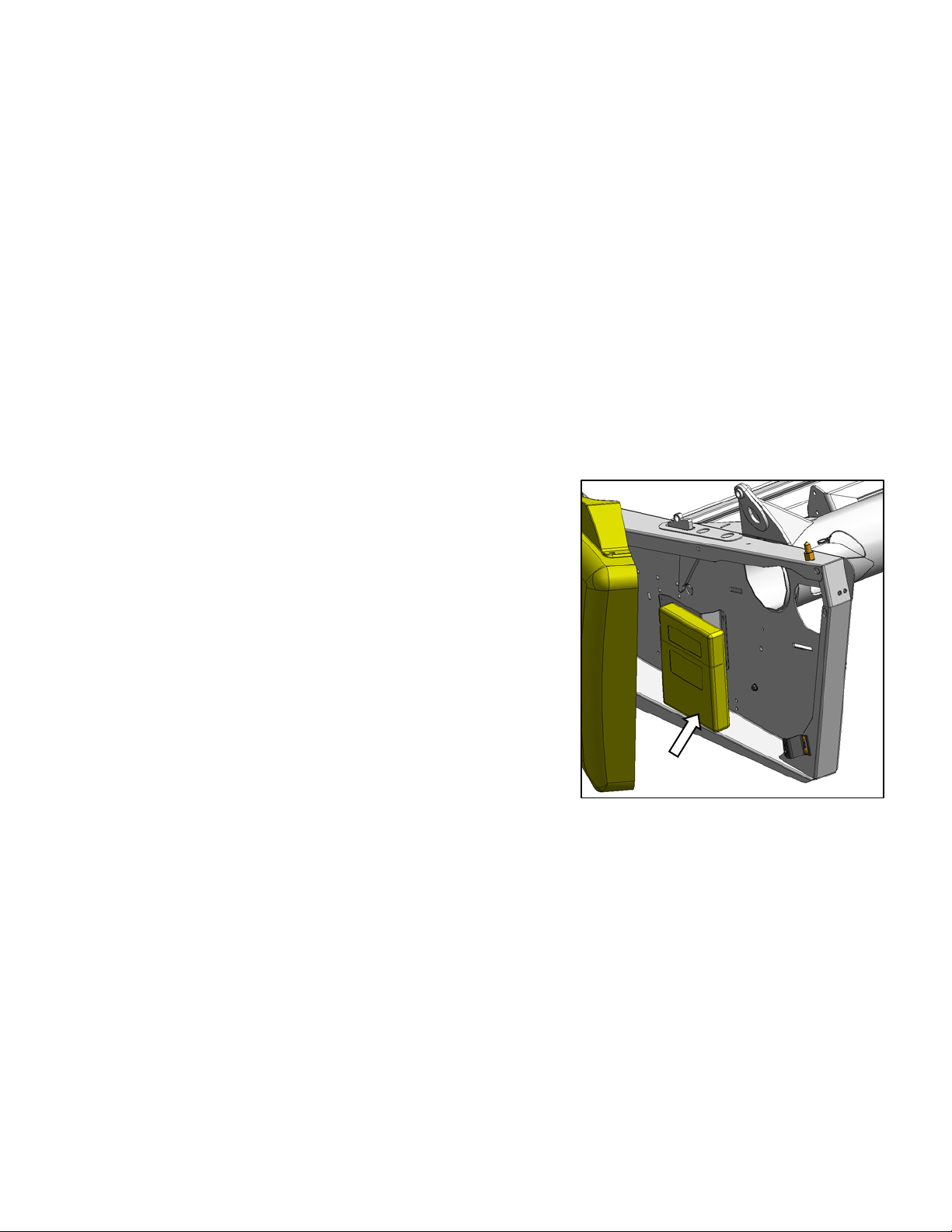
Serial Number Plate is located on the underside of the LH endsheet.
ADAPTER MODEL________SERIAL NO.______________YEAR_____
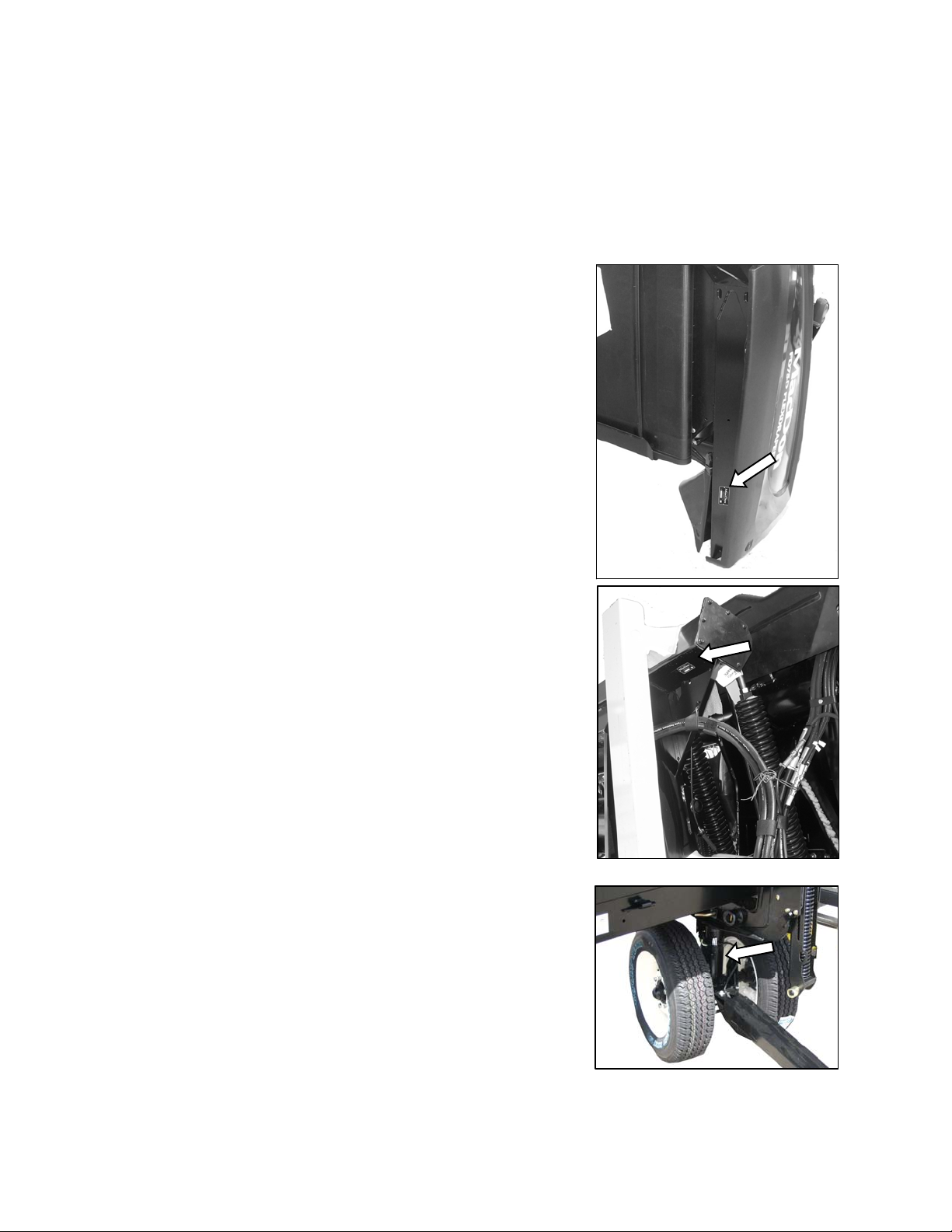
Serial Number Plate is located on the underside of the reservoir at the right
end.
SLOW SPEED TRANSPORT/STABILIZER WHEEL OPTION
SERIAL NO.__________________YEAR_____
Serial Number Plate is located on the left hand wheel pivot tube.
Form 169593 2 Revision B
Page 5

CONTENTS
Section/Title Page
1 INTRODUCTION ............................................................................................................................................. 1
2 MODEL AND SERIAL NUMBER .................................................................................................................... 2
3 SAFETY ........................................................................................................................................................... 6
3.1 SAFETY ALERT SYMBOL .................................................................................................................... 6
3.2 SIGNAL WORDS................................................................................................................................... 6
3.3 SAFETY DECALS ................................................................................................................................. 6
3.3.1 Safety Decal Installation ............................................................................................................... 6
3.3.2 Safety Decal Locations ................................................................................................................. 7
3.3.3 Safety Sign Definitions ................................................................................................................ 13
3.4 GENERAL SAFETY ............................................................................................................................ 16
4 DEFINITIONS ................................................................................................................................................ 18
5 COMPONENT IDENTIFICATION .................................................................................................................. 19
5.1 COMBINE HEADER ............................................................................................................................ 19
5.2 COMBINE ADAPTER .......................................................................................................................... 20
6 SPECIFICATIONS ......................................................................................................................................... 21
7 OPERATION .................................................................................................................................................. 23
7.1 OWNER/OPERATOR RESPONSIBILITIES ....................................................................................... 23
7.2 OPERATIONAL SAFETY .................................................................................................................... 23
7.2.1 Header Lift Cylinder Locks .......................................................................................................... 24
7.2.2 Reel Props .................................................................................................................................. 24
7.2.3 Endshields ................................................................................................................................... 25
7.2.4 Daily Start-Up Check................................................................................................................... 27
7.3 HEADER ATTACHMENT / DETACHMENT ........................................................................................ 28
7.3.1 Adapter Set-up ............................................................................................................................ 28
7.3.2 Case IH 7010, 8010, 7120, 8120, 5088, 6088, 7088 .................................................................. 31
7.3.3 John Deere 60, 70, and S Series ................................................................................................ 35
7.3.4 CAT Lexion 500, 700 Series ....................................................................................................... 39
7.3.5 New Holland CR, CX................................................................................................................... 43
7.3.6 AGCO .......................................................................................................................................... 47
7.4 ATTACHING AND DETACHING HEADER WITH ADAPTER ............................................................. 52
7.4.1 Detaching .................................................................................................................................... 52
7.4.2 Attaching ..................................................................................................................................... 55
7.5 BREAK-IN PERIOD ............................................................................................................................. 59
7.6 SHUTDOWN PROCEDURE ............................................................................................................... 59
7.7 HEADER CONTROLS ........................................................................................................................ 59
7.8 HEADER SET-UP ............................................................................................................................... 60
7.8.1 Header Settings .......................................................................................................................... 60
7.8.2 Pickup Reel Settings ................................................................................................................... 61
7.9 HEADER OPERATING VARIABLES .................................................................................................. 63
7.9.1 Cutting Height ............................................................................................................................. 63
7.9.2 Header Float ............................................................................................................................... 66
7.9.3 Header Angle .............................................................................................................................. 69
7.9.4 Reel Speed ................................................................................................................................. 70
7.9.5 Ground Speed ............................................................................................................................. 71
7.9.6 Draper Speed .............................................................................................................................. 72
7.9.7 Knife Speed ................................................................................................................................. 73
7.9.8 Reel Height ................................................................................................................................. 74
7.9.9 Reel Fore-Aft Position ................................................................................................................. 74
7.9.10 Reel Tine Pitch ............................................................................................................................ 78
7.9.11 Crop Divider Rods ....................................................................................................................... 80
7.9.12 Crop Dividers .............................................................................................................................. 80
169593 3 Revision B
Page 6

CONTENTS
Section/Title Page
7.9.13 Rice Dividers ............................................................................................................................... 82
7.10 KNIFE HEAD SHIELD ......................................................................................................................... 83
7.11 HEADER LEVELLING ......................................................................................................................... 84
7.12 UNPLUGGING CUTTERBAR .............................................................................................................. 85
7.13 UNPLUGGING ADAPTER ................................................................................................................... 85
7.14 UPPER CROSS AUGER ..................................................................................................................... 86
7.15 TRANSPORTING HEADER ................................................................................................................ 87
7.15.1 Combine ...................................................................................................................................... 87
7.15.2 Towing ......................................................................................................................................... 87
7.15.3 Converting from Transport to Field Position ................................................................................ 88
7.15.4 Converting from Field to Transport Position ................................................................................ 93
8 MAINTENANCE AND SERVICING ............................................................................................................... 96
8.1 PREPARATION FOR SERVICING ...................................................................................................... 96
8.2 RECOMMENDED SAFETY PROCEDURES ...................................................................................... 96
8.3 MAINTENANCE SPECIFICATIONS .................................................................................................... 97
8.3.1 Recommended Torques .............................................................................................................. 97
8.3.2 Roller Chain Installation............................................................................................................. 100
8.3.3 Sealed Bearing Installation ........................................................................................................ 100
8.3.4 Recommended Fluids and Lubricants ....................................................................................... 101
8.3.5 Conversion Chart ....................................................................................................................... 102
8.4 MAINTENANCE REQUIREMENTS ................................................................................................... 103
8.4.1 Maintenance Schedule/Record ................................................................................................. 104
8.4.2 Break-In Inspections .................................................................................................................. 106
8.4.3 Pre-Season/Annual Service ...................................................................................................... 107
8.4.4 End of Season ........................................................................................................................... 107
8.4.5 Lubrication and Servicing .......................................................................................................... 108
8.5 HYDRAULICS .................................................................................................................................... 118
8.5.1 Reservoir ................................................................................................................................... 118
8.5.2 Hydraulic Oil Filter ..................................................................................................................... 120
8.5.3 Hoses and Lines ........................................................................................................................ 120
8.6 ELECTRICAL ..................................................................................................................................... 121
8.7 MAIN DRIVE ...................................................................................................................................... 121
8.7.1 Driveline Removal ..................................................................................................................... 121
8.7.2 Driveline Installation .................................................................................................................. 122
8.7.3 Guard Removal ......................................................................................................................... 122
8.7.4 Guard Installation ...................................................................................................................... 123
8.7.5 Gearbox Drive Chain Adjustment .............................................................................................. 124
8.8 AUGER .............................................................................................................................................. 125
8.8.1 Auger Pan Clearance ................................................................................................................ 125
8.8.2 Auger Drive Chain Adjustment .................................................................................................. 126
8.8.3 Auger Drive Chain Replacement ............................................................................................... 127
8.8.4 Auger Tine Replacement ........................................................................................................... 128
8.9 SICKLE AND SICKLE DRIVE ............................................................................................................ 130
8.9.1 Sickle Sections .......................................................................................................................... 130
8.9.2 Sickle Removal .......................................................................................................................... 131
8.9.3 Sickle Head Bearing Replacement ............................................................................................ 131
8.9.4 Sickle Installation ....................................................................................................................... 132
8.9.5 Spare Sickle .............................................................................................................................. 132
8.9.6 Sickle Guards ............................................................................................................................ 133
8.9.7 Sickle Hold-Downs .................................................................................................................... 135
8.9.8 Sickle Drive Belts: Non-Timed Drive ......................................................................................... 136
8.9.9 Double Knife Drive Belts: Timed Drive ...................................................................................... 137
169593 4 Revision B
Page 7

CONTENTS
Section/Title Page
Sickle Drive Box ........................................................................................................................ 142
8.9.10
8.10 ADAPTER FEED DRAPER ............................................................................................................... 145
8.10.1 Draper Tension Adjustment ...................................................................................................... 145
8.10.2 Replacing Draper ...................................................................................................................... 145
8.11 HEADER DRAPERS ......................................................................................................................... 147
8.11.1 Header Draper Tension Adjustment ......................................................................................... 147
8.11.2 Replacing Split Draper .............................................................................................................. 147
8.11.3 Header Draper Alignment ......................................................................................................... 149
8.11.4 Draper Roller Maintenance ....................................................................................................... 150
8.11.5 Deck Height ............................................................................................................................... 152
8.12 REEL AND REEL DRIVE .................................................................................................................. 153
8.12.1 Reel Clearance to Cutterbar ..................................................................................................... 153
8.12.2 Reel Frown Adjustment ............................................................................................................. 155
8.12.3 Reel Centering .......................................................................................................................... 155
8.12.4 Reel Drive Chain ....................................................................................................................... 156
8.12.5 Reel Drive Sprocket .................................................................................................................. 163
8.12.6 Reel Drive U-joint: Double Reel ................................................................................................ 167
8.12.7 Reel Drive Motor ....................................................................................................................... 169
8.12.8 Reel Speed Sensor ................................................................................................................... 174
8.12.9 Reel Tines ................................................................................................................................. 177
8.12.10 Tine Tube Bushings .................................................................................................................. 179
8.13 TRANSPORT SYSTEM (OPTIONAL) .................................................................................................. 183
8.13.1 Wheel Bolt Torque .................................................................................................................... 183
8.13.2 Axle Bolts .................................................................................................................................. 183
8.13.3 Tire Inflation .............................................................................................................................. 184
9 TROUBLESHOOTING ................................................................................................................................ 185
9.1 CROP LOSS AT CUTTERBAR ......................................................................................................... 185
9.2 CUTTING ACTION AND SICKLE COMPONENTS ........................................................................... 186
9.3 REEL DELIVERY .............................................................................................................................. 188
9.4 HEADER AND DRAPERS ................................................................................................................. 190
9.5 CUTTING EDIBLE BEANS ................................................................................................................ 193
10 OPTIONS AND ATTACHMENTS ............................................................................................................... 196
10.1 ADJUSTABLE SKID SHOES WITH POLY COVER .......................................................................... 196
10.2 STUB GUARD CONVERSION KIT ................................................................................................... 196
10.3 STABILIZER WHEELS ...................................................................................................................... 196
10.4 STABILIZER/TRANSPORT WHEELS .............................................................................................. 196
10.5 LODGED CROP REEL FINGER KIT ................................................................................................. 197
10.6 VERTICAL KNIFE MOUNTS ............................................................................................................. 197
10.7 UPPER CROSS AUGER ................................................................................................................... 197
10.8 REEL ENDSHIELD KIT ..................................................................................................................... 197
10.9 ROCK RETARDER KIT ..................................................................................................................... 198
10.10 RICE DIVIDER RODS ....................................................................................................................... 198
10.11 DIVIDER LATCH KIT ......................................................................................................................... 198
10.12 DELICATE SEED SAVER KIT ........................................................................................................... 198
10.13 KNIFE HEAD SHIELD ....................................................................................................................... 198
10.14 DRAPER WIDE DEFLECTOR KIT .................................................................................................... 198
11 UNLOADING AND ASSEMBLY ................................................................................................................. 199
INDEX ………………………………………………………………………………….……………....…………..….200
169593 5 Revision B
Page 8
SECTION 3. SAFETY
3 SAFETY
3.1 SAFETY ALERT SYMBOL
This safety alert symbol indicates important
safety messages in this manual and on safety
decals on the machine.
This symbol means:
ATTENTION!
BECOME ALERT!
YOUR SAFETY IS INVOLVED!
Carefully read and follow the safety message
accompanying this symbol.
WHY IS SAFETY IMPORTANT TO YOU?
ACCIDENTS DISABLE AND KILL.
ACCIDENTS COST.
ACCIDENTS CAN BE AVOIDED.
3.2 SIGNAL WORDS
Note the use of the signal words DANGER,
WARNING, and CAUTION with safety messages.
The appropriate signal word for each message has
been selected using the following guidelines:
DANGER
Indicates an imminently hazardous
situation that, if not avoided, will result in
death or serious injury.
WARNING
Indicates a potentially hazardous situation
that, if not avoided, could result in death
or serious injury. It is also used to alert
against unsafe practices.
CAUTION
Indicates a potentially hazardous situation
that, if not avoided, may result in minor or
moderate injury. It is also used as a
reminder of good safety practices.
3.3 SAFETY DECALS
a. The safety decals appear on the header at the
locations shown on pages 7 to 11.
b. Keep safety decals clean and legible at all
times.
c. Replace safety decals that are missing or
become illegible.
d. If original parts on which a safety decal was
installed are replaced, be sure the repair part
also bears the current safety decal.
e. Safety decals are available from your MacDon
Dealer Parts Department.
3.3.1 Safety Decal Installation
a. Be sure the installation area is clean and dry.
b. Decide on the exact location before you remove
the decal backing paper.
c. Remove the smaller portion of the split backing
paper.
d. Place the decal in position and slowly peel back
the remaining paper, smoothing the decal as it
is applied.
e. Small air pockets can be smoothed out or
pricked with a pin.
169593 6 Revision B
Page 9
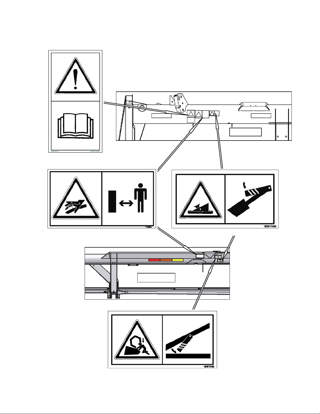
3.3.2 Safety Decal Locations
BOTH ENDS #113482
SECTION 3. SAFETY
20 FT
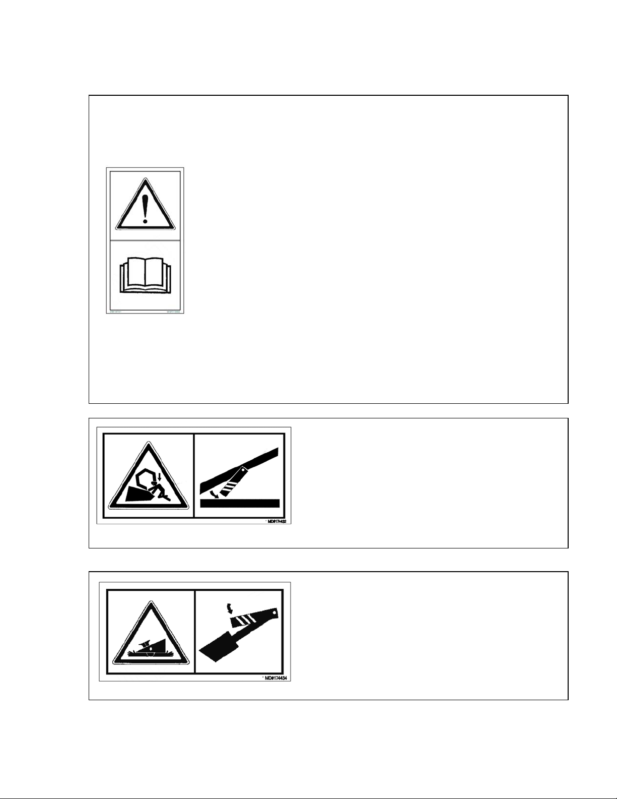
BACKTUBE #174474
BACKTUBE - BOTH ENDS #174434
BACKTUBE #174432
169593 7 Revision B
Page 10
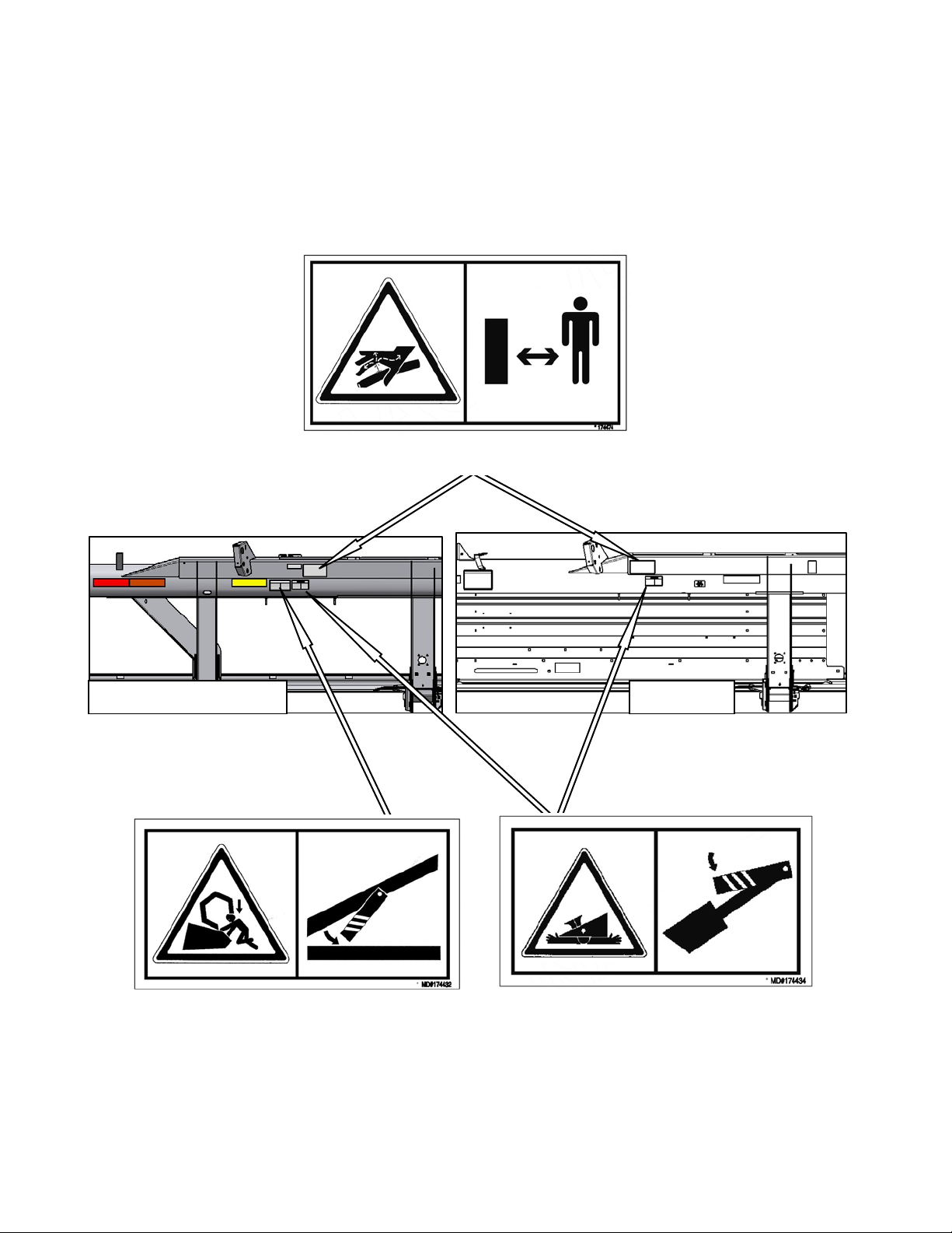
Safety Decal Locations (cont’d)
SECTION 3. SAFETY
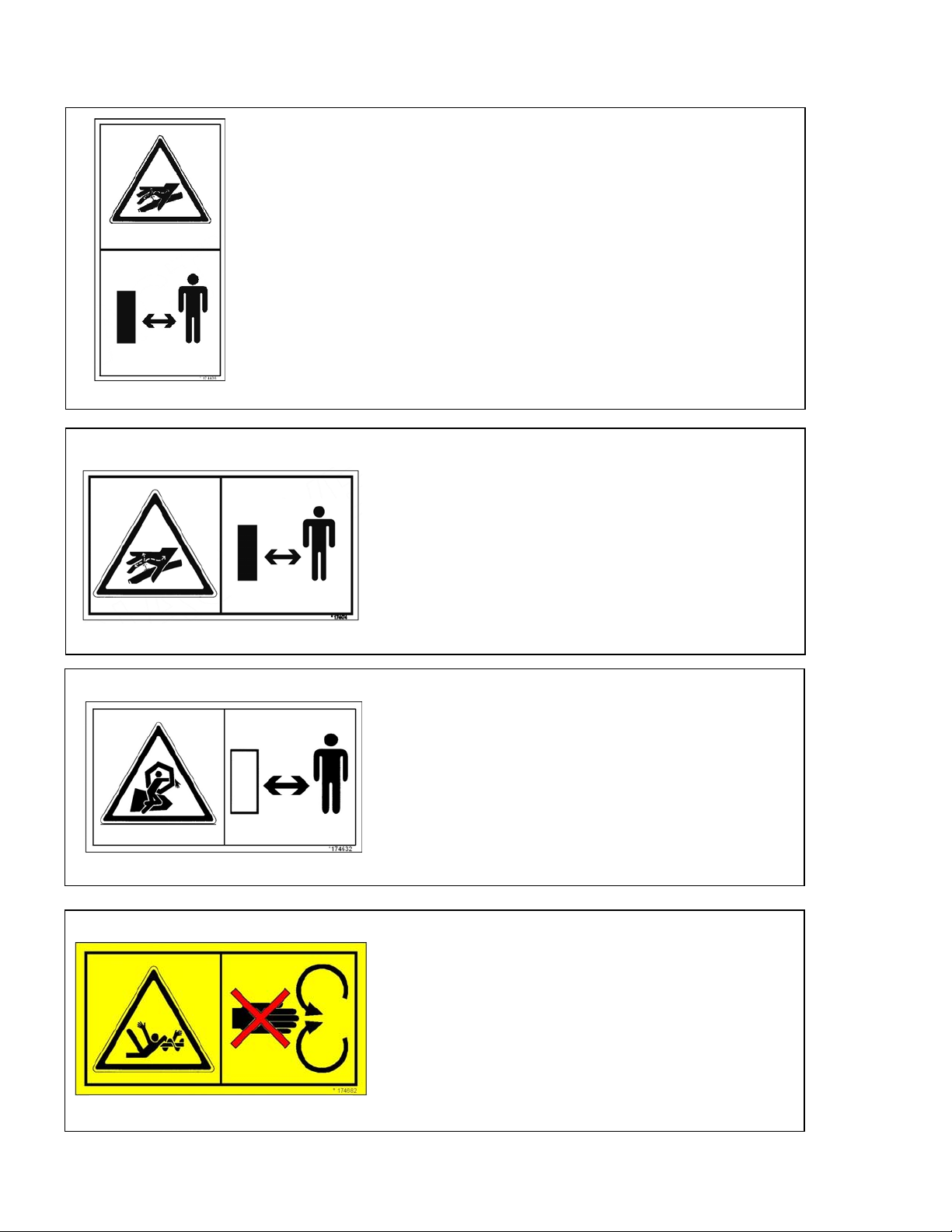
BACK TUBE - BOTH ENDS
30, 35, 40 FT 25 FT
BACK TUBE - DOUBLE REEL ONLY
#174432
BACK TUBE - BOTH ENDS
#174434
169593 8 Revision B
Page 11
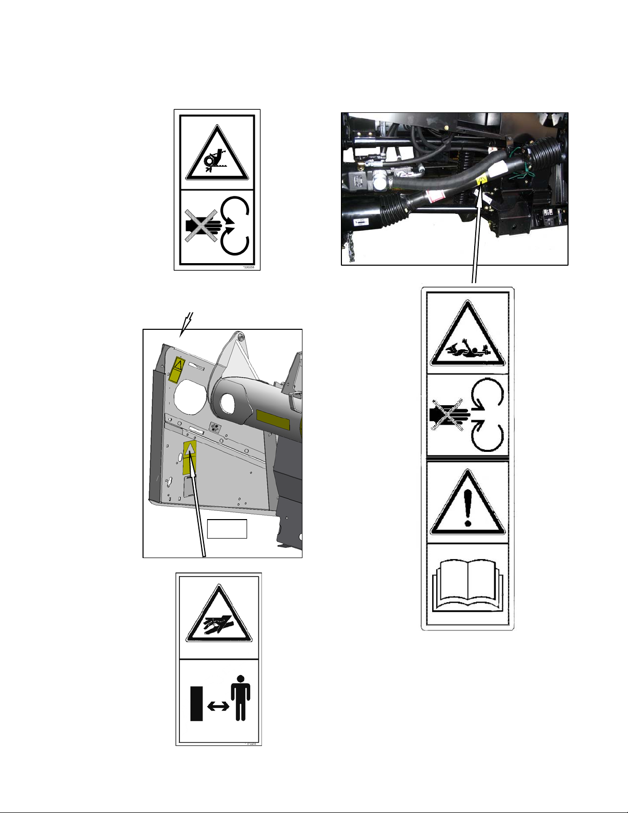
Safety Decal Locations (cont’d)
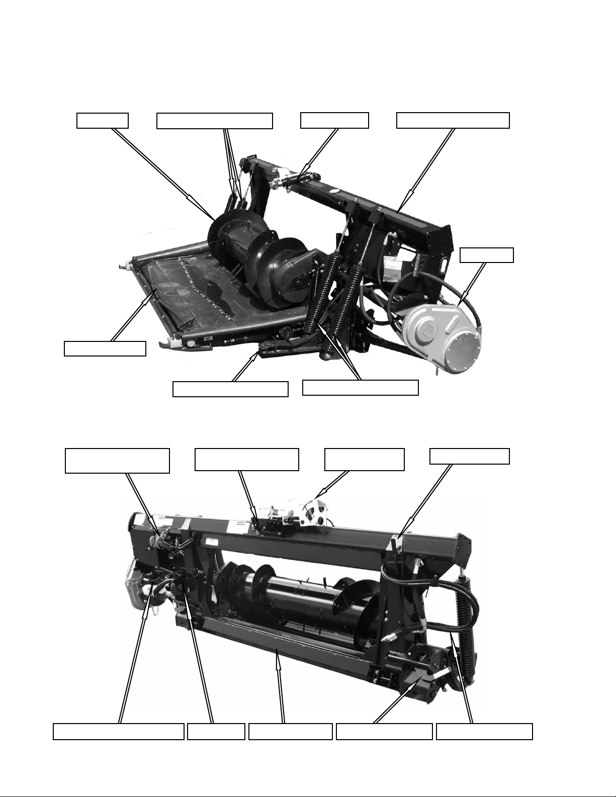
BOTH ENDS - DOUBLE KNIFE
LEFT END - SINGLE KNIFE
#220238
SECTION 3. SAFETY
ALL
DRIVELINE
#194521
LEFT END #174436
169593 9 Revision B
Page 12
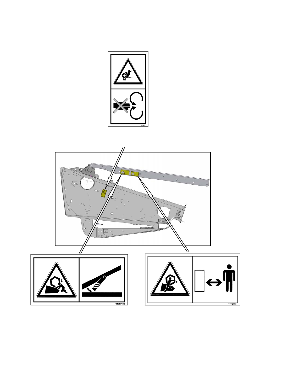
Safety Decal Locations (cont’d)
BOTH ENDS - DOUBLE KNIFE
SECTION 3. SAFETY
LEFT END - SINGLE KNIFE
#220238
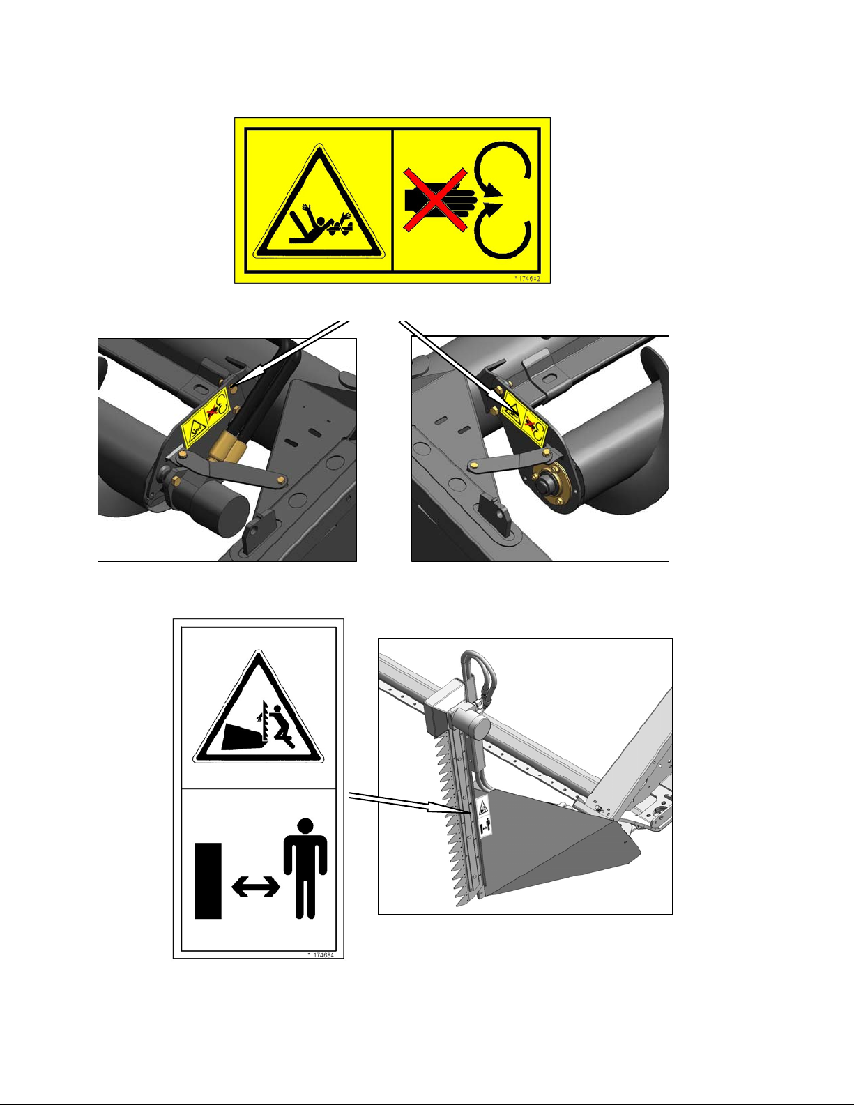
REEL ARMS
#174432
169593 10 Revision B
LH & RH REEL ARMS
#174632
Page 13
Safety Decal Locations (cont’d)
SECTION 3. SAFETY
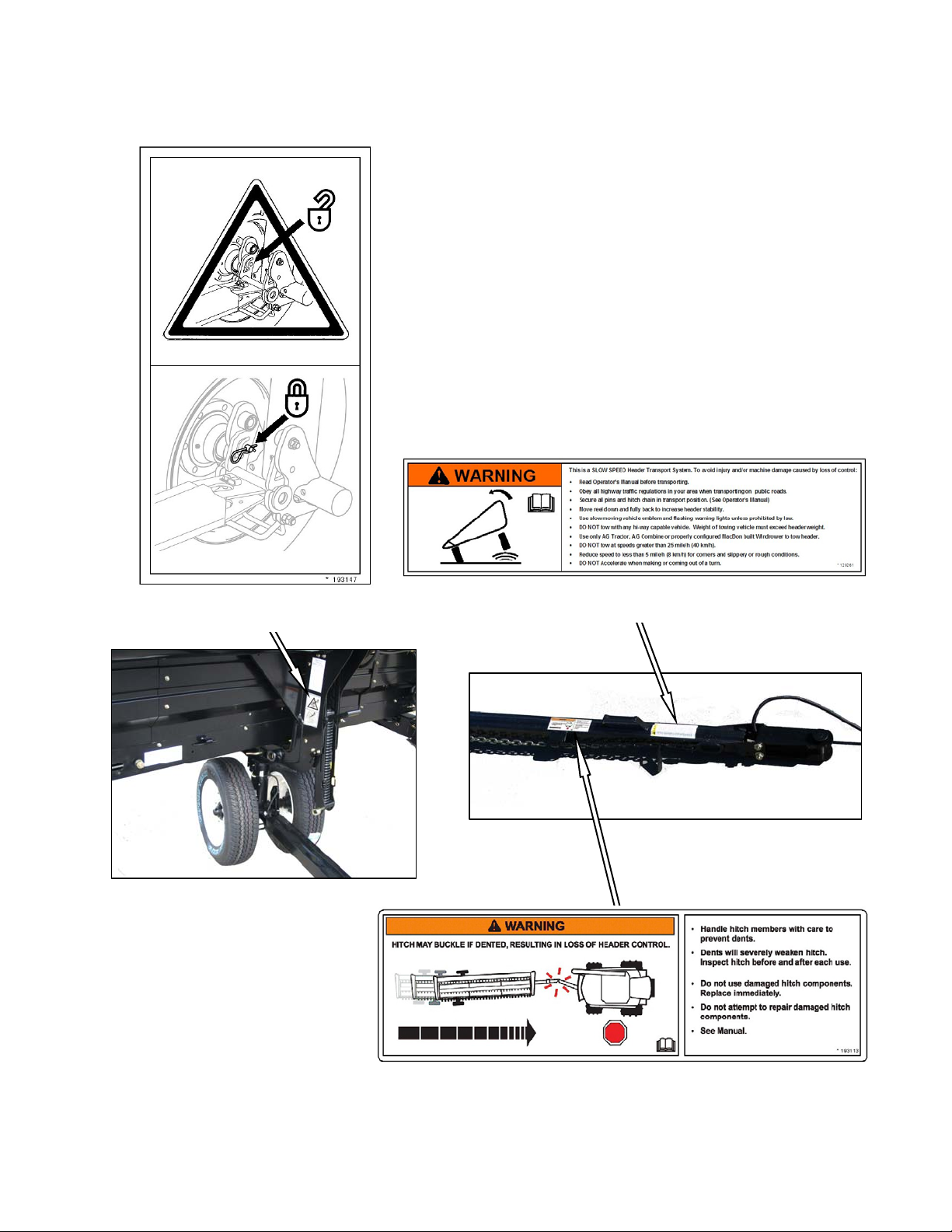
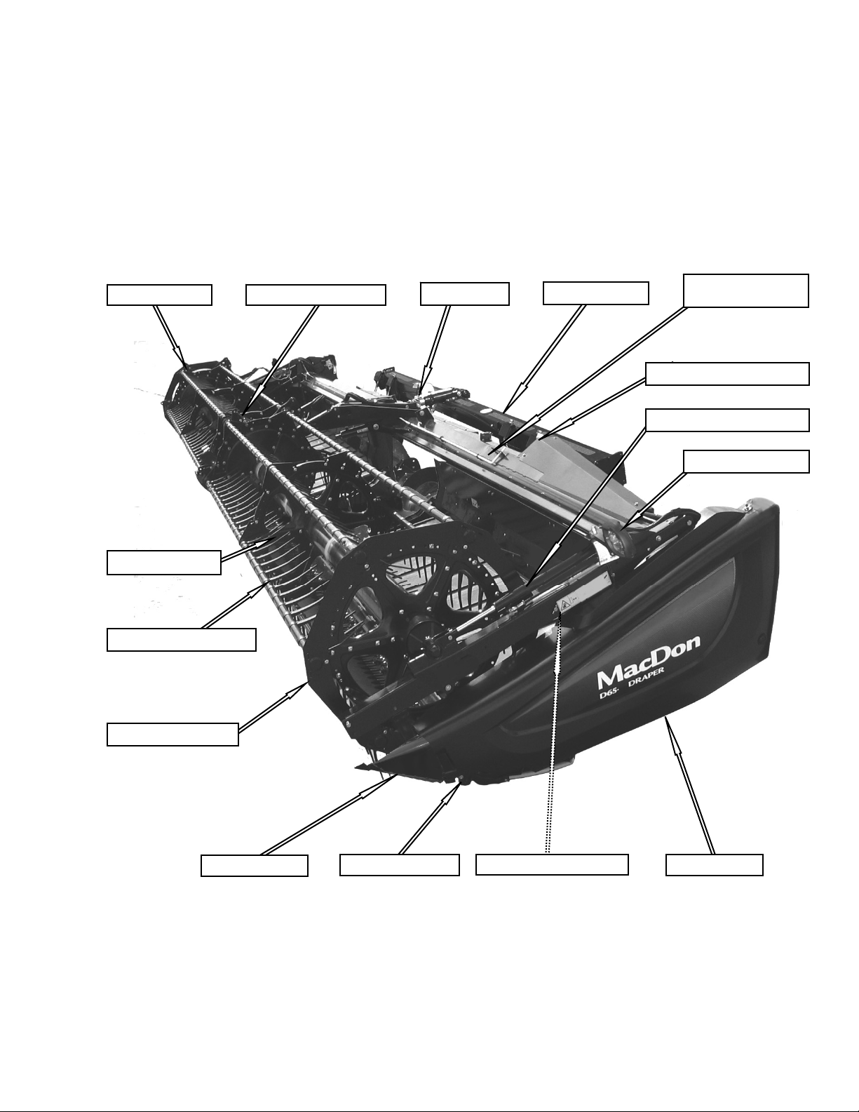
FRONT TRANSPORT LEG
#193147
TOW-BAR
#129261
TOW-BAR
#193113
169593 11 Revision B
Page 14
Safety Decal Locations (cont’d)
SECTION 3. SAFETY
UPPER CROSS AUGER
#174682
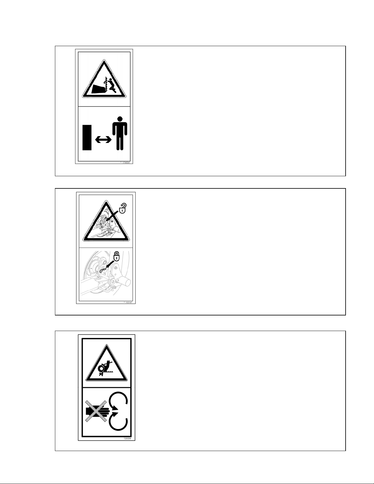
LH AND RH
VERTICAL KNIFE
#174684
169593 12 Revision B
Page 15
3.3.3 Safety Sign Definitions
General Hazard Pertaining To Machine Operation And Servicing.
To avoid injury or death from improper or unsafe machine operation:
Read the Operator’s Man ual, and follow all safet y instructions. If you do not have
a manual, obtain one from your dealer.
Do not allow untrained persons to operate the machine.
Review safety instructions with all operators annually.
Ensure that all safety signs are installed and legible.
Make certain everyone is clear of machine before starting engine and during
operation.
Keep riders off the machine.
Keep all shields in place, and stay clear of moving parts.
Disengage header driv e, put transmission in neutral and wait for all movement to
113482
stop before leaving operator’s position.
Shut off engine and remove key from ignition before servicing, adjusting,
lubricating, cleaning, or unplugging machine.
Engage locks to prevent l owering of header or reel befor e servicing in the raised
position.
Use slow moving vehicle emblem and flash ing warning lights when operating on
roadways unless prohibited by law.
SECTION 3. SAFETY
CAUTION
174432
174434
Reel Hazard
WARNING
To avoid injury from fall of raised reel; fully raise reel,
stop engine, remove key, and engage mechanical lock
on each reel support arm before working on or under
reel.
See Operator’s Manual.
Header Hazard
DANGER
Rest header on ground or engage mechanical locks
before going under unit.
169593 13 Revision B
Page 16
174436
174474
SECTION 3. SAFETY
High Pressure Oil Hazard
WARNING
Do not go near leaks
High pressure oil easily punctures skin causing serious in jury, gangrene or
death.
If injured, seek emergency m edical help. Immediate surger y is required to
remove oil.
Do not use finger or skin to check for leaks.
Lower load or relieve hydraulic pressure before loosening fittings.
Hydraulic Oil Pressure Hazard
CAUTION
Do not go near leaks
High pressure oil easily punctures skin causing serious
injury, gangrene or death.
If injured, seek emergency medical help.
Immediate surgery is required to remove oil.
Do not use finger or skin to check for leaks.
Lower load or relieve pressure before loosening fittings.
Reel Entanglement Hazard
CAUTION
To avoid injury from entanglement with rotating reel,
stand clear of header while machine is running.
174632
Auger Entanglement Hazard
CAUTION
To avoid injury from entanglement with rotating
auger, stand clear of header while machine is
running.
174682
169593 14 Revision B
Page 17
SECTION 3. SAFETY
Sharp Component Hazard
CAUTION
Knife Sections are Sharp
Wear heavy canvas or leather gloves when working with knife.
Be sure no one is near the vertical knife when removing or rotating
knife.
174684
193147
Transport/Roading Hazard
WARNING
Before Transporting
Ensure tow-bar lock mechanism is locked.
Keep Shields in Place Hazard
WARNING
To avoid injury, stop engine before opening power drive system
shield.
Keep all shields in place.
220238
169593 15 Revision B
Page 18

SECTION 3. SAFETY
3.4 GENERAL SAFETY
CAUTION
The following are general farm safety
precautions that should be part of your
operating procedure for all types of
machinery.
Protect yourself. When assembling,
operating and servicing machinery, wear
all the protective clothing and personal
safety devices that COULD be necessary
for the job at hand. Don't take chances.
You may need:
o a hard hat.
o protective shoes with slip
resistant soles.
o protective glasses or goggles.
o heavy gloves.
o wet weather gear.
o respirator or filter mask.
Provide a first-aid kit for use in case of
emergencies.
Keep a fire extinguisher on the machine.
Be sure the extinguisher is properly
maintained and be familiar with its
proper use.
Keep young children away from
machinery at all times.
Be aware that accidents often happen
when the Operator is tired or in a hurry
to get finished. Take the time to
consider the safest way. Never ignore
warning signs of fatigue.
Wear close-fitting clothing
and cover long hair.
Never wear dangling items
such as scarves or
bracelets.
Keep hands, feet, clothing and hair away
from moving parts. Never attempt to
clear obstructions or objects from a
machine while the engine is running.
A
B
o hearing protection. Be aware that
prolonged exposure to loud
noise can cause impairment or
loss of hearing. Wearing a
suitable hearing protective
device such as ear muffs (A) or
ear plugs (B) protects against
objectionable or loud noises.
169593 16 Revision B
Keep all shields in place. Never alter or
remove safety equipment. Make sure
driveline guards can rotate
independently of the shaft and can
telescope freely.
(continued next page)
Page 19

SECTION 3. SAFETY
Use only service and repair parts made
or approved by the equipment
manufacturer. Substituted parts may not
meet strength, design, or safety
requirements.
Do NOT modify the machine.
Unauthorized modifications may impair
the function and/or safety and affect
machine life.
Stop engine, and remove key from
ignition before leaving Operator's seat
for any reason. A child or even a pet
could engage an idling machine.
Keep the area used for servicing
machinery clean and dry. Wet or oily
floors are slippery. Wet spots can be
dangerous when working with electrical
equipment. Be sure all electrical outlets
and tools are properly grounded.
Use adequate light for the job at hand.
Keep machinery clean. Straw and chaff
on a hot engine are a fire hazard. Do
NOT allow oil or grease to accumulate
on service platforms, ladders or
controls. Clean machines before
storage.
Never use gasoline, naphtha or any
volatile material for cleaning purposes.
These materials may be toxic and/or
flammable.
When storing machinery, cover sharp or
extending components to prevent injury
from accidental contact.
169593 17 Revision B
Page 20

SECTION 4. DEFINITIONS
4 DEFINITIONS
The following terms/abbreviations may be used in this manual:
TERM DEFINITION
AHHC
API
ASTM
Center-link
DK
GSL
Header
rpm
SAE
SK
spm
Tractor
Automatic Header Height Control
American Petroleum Institute
American Society Of Testing and Materials
A hydraulic cylinder or turnbuckle type link between the header and the
machine that tilts the header
Double Knife
Ground Speed Lever
A machine that cuts and lays crop into a windrow, and is attached to a
self-propelled windrower or combine
Revolutions per minute
Society Of Automotive Engineers
Single Knife
Strokes per minute
Agricultural type tractor
Truck
A four-wheel highway/road vehicle weighing no less than
7500 lb. (3400 kg)
169593 18 Revision B
Page 21
SECTION 5. COMPONENT IDENTIFICATION
5 COMPONENT IDENTIFICATION
5.1 COMBINE HEADER
PICK-UP REEL
TRANSITION PAN
PICK-UP REEL FINGERS
REEL DRIVE AND CAM
CENTER-LINK
CA25 ADAPTER
CENTER REEL ARM
PROP HANDLE
HYDRAULIC CONNECTIONS
REEL FORE-AFT CYLINDER
TRANSPORT LIGHT
REEL ENDSHIELDS
CROP DIVIDER
169593 19 Revision B
SICKLE DRIVE BOX
REEL LIFT CYLINDER
ENDSHIELD
Page 22
SECTION 5. COMPONENT IDENTIFICATION
5.2 COMBINE ADAPTER
AUGER
FEED DRAPER
HEADER FLOAT SPRINGS
HEADER SUPPORT ARM
CENTER-LINK HYDRAULIC RESERVOIR
GEARBOX
HEADER FLOAT SPRINGS
COMBINE HYDRAULICS
MULTI-COUPLER
RESERVOIR OIL LEVEL
SIGHT GLASS
DRIVELINE DRAPER / KNIFE DRIVE PUMP
TRANSITION FRAME
HEADER AUTO
HEIGHT CONTROL
HEADER FLOAT LOCK
TORQUE WRENCH
HOSES TO HEADER
169593 20 Revision B
Page 23

6 SPECIFICATIONS
HEADER SIZE 20 FT 25 FT 30 FT 35 FT 40 FT 45 FT
OVERALL
Width
(Inches [mm])
Length
(Inches [mm])
Height -Transport
Estimated Weight Range
Base Header - No Adapter (lb [kg])
CUTTERBAR
Width (Inches (mm)
Header Cutting
Height
Guard Angle (Cutterbar on Ground)
SICKLE
Drive Type
Sickle Speed
Strokes Per Minute)
(
Stroke
Sections - Over-Serrated and
Bolted (serrations/inch)
Guards and Hold-Downs
CONVEYOR AND DECKS
Draper Drive
Draper Width
Draper Speed
Delivery Opening Width
REEL
Drive
Speed
Quantity of Tine Tubes
Effective Reel Diameter
Transport (Reel Full Aft)
with CA25 Adapter
Field
Transport
(with Tow Pole)
Shortest Center-Link
Longest Center-Link
Single Knife (SK)
Double Knife (DK)
Single Knife (SK)
Double Knife (DK)
Solid
Pointed
Stub
Tip Radius Range
SECTION 6. SPECIFICATIONS
106 (2684) Long Dividers Installed
98 (2500) Long Dividers Removed
255 (6479) 315 (8003) 375 (9527) 435 (11051) 495 (12575) 555 (14099)
Not Applicable
3400 (1544)
240 (6096) 300 (7620) 360 (9144) 420 (10668) 480 (12192) 540 (13716)
1-5/16 in. (32 mm)
below ground – 52-5/16 in.
(1328 mm) above
4-5/8 in. (117 mm) below
ground – 46-7/8 in. (1192 mm)
Hydraulic Motor / Two ‘B’ Timing Belts / Two Heavy Duty (MD)
Not Applicable 1200–1450 1200–1400 1100–1300 1050–1200 Not Applicable
Sheet Metal HD Not Applicable
9 6 / 9 5 / 6 5
3500–4100
(1589–1861)
above
7.0°–12.4° 2.0°–7.4°
Hydraulic Motor / ‘C’ Belt/Heavy Duty (MD) Sickle Drive Box
Sickle Drive Boxes
1400–1700 1200–1500 1100–1400
14 9 / 14 9
Case Hardened or Double Heat Treated / Sheet Metal / Adjuster Bolt
Hydraulic From Combine Hydraulic Oil Supply
505-3/4
(12845)
97 in. (2464 mm)
4200–5100
(1907–2315)
13/16 in. (20 mm) below ground–52-13/16 in. (1340 mm) above
4-1/8 in. (105 mm) below ground–47-3/8 in. (1204 mm) above
3 in. (76 mm)
41-5/8 in. (1057 mm)
247–464 ft/min (75–141 m/min)
73-5/8 in. (1870 mm)
65 in. (1650 mm)
30-3/16–31-1/2 in. (766–800 mm)
4700–5700
(2134–2588)
Hydraulic
0–67 rpm
547-1/2
(13907)
601-1/2
(15278)
5400–5800
(2451–2633)
Two Hydraulic Motors To ‘C’
Belts, Untimed To Heavy Duty
(MD) Sickle Drive Boxes.
631-1/2 (16040)
6200 (2815)
HD Plastic -
Fingers
Type Steel
Spacing
SR
Steel or Plastic
- DR
6 in. (152 mm)
HD Plastic
(continued next page)
169593 21 Revision B
Page 24

SECTION 6. SPECIFICATIONS
HEADER SIZE 20 FT 25 FT 30 FT 35 FT 40 FT 45 FT
UPPER CROSS AUGER
Outside Diameter
Weight (lb [kg])
STABILIZER WHEELS / SLOW SPEED TRANSPORT
Size
Pressure
COMBINE ADAPTER
Width
Length
Height
Weight
Main Drive
Gearbox Capacity
Drive
Auger
Type
Speed
Drive
Feed Draper
Type
Width
Speed
Reservoir Capacity
Maximum Operating Pressure
Filter
Header Draper Drive Pump
Sickle Drive Pump
Adapter Header Flotation
135 (62) 205 (93) 235 (107) 265 (120) 295 (134)
Not Applicable
3500 psi (24132 kPa) Piston Pump, 3700 psi (25510 kPa) Gear Pump
12 in. (305 mm)
ST205/75 R15
Load Range E - 85 psi (586 kPa)
151 inches (3835 mm)
70 inches (1778 mm)
50 inches (1270 mm)
2,050 lb (930 kg)
Combine Driven Piston Pump and Gear Pump Through Gearbox
5 Pints (2.5 liters)
Chain
Auger - 14 inches (356 mm) with 4 inch (102 mm) Flighting
150 rpm (Combine Dependent)
Hydraulic Motor from Combine Driven Pump
Self-Tracking Rubber Coated Polyester Fabric With Rubber Slats
78-3/4 inches (2000 mm)
350–400 ft / min (107–122 meters / min)
16 U.S. gal (60 liters)
10 micron #151975
1.01 in.3 (16.5 cc) Gear Pump
1.8–2.7 in.3 (29.5–44.2 cc) Piston Pump
7–8 inches (178–203 mm) vertical, 4 degrees rotation
Header Angle Control
Combine Requirement
* See chart under Knife Speed for recommended range.
Mechanical or Hydraulic From Combine Hydraulic Oil Supply
(With Solenoid Valve To Toggle To Reel Fore-aft / Header Tilt)
Class 5 or Higher
NOTES: 1. Specifications and design are subject to change without notice or obligation to revise previously sold units.
169593 22 Revision B
2. Weights do not include options.
Page 25
SECTION 7. OPERATION
7 OPERATION
7.1 OWNER/OPERATOR
RESPONSIBILITIES
CAUTION
It is your responsibility to read and
understand this manual completely
before operating the header. Contact
your MacDon Dealer if an instruction is
not clear to you.
Follow all safety messages in the
manual and on safety decals on the
machine.
Remember that YOU are the key to
safety. Good safety practices protect
you and the people around you.
Before allowing anyone to operate the
header, for however short a time or
distance, make sure they have been
instructed in its safe and proper use.
Review the manual and all safety related
items with all Operators annually.
Be alert for other Operators not using
recommended procedures or not
following safety precautions. Correct
these mistakes immediately, before an
accident occurs.
Do NOT modify the machine.
Unauthorized modifications may impair
the function and/or safety and affect
machine life.
The safety information given in this
manual does not replace safety codes,
insurance needs, or laws governing
your area. Be sure your machine meets
the standards set by these regulations.
7.2 OPERATIONAL SAFETY
Follow these safety precautions:
CAUTION
Follow all safety and operational
instructions given in your Operator's
Manuals. If you do not have a combine
manual, get one from your MacDon
Dealer and read it thoroughly.
Never attempt to start the engine or
operate the machine except from the
combine seat.
Check the operation of all controls in a
safe clear area before starting work.
Do NOT allow riders on combine.
Never start or move the machine until
you are sure all bystanders have cleared
the area.
Avoid travelling over loose fill, rocks,
ditches or holes.
Drive slowly through gates and
doorways.
When working on inclines, travel uphill
or downhill when possible. Be sure to
keep transmission in gear when
travelling downhill.
Never attempt to get on or off a moving
machine.
Do NOT leave Operator’s station while
the engine is running.
(continued next page)
169593 23 Revision B
Page 26
SECTION 7. OPERATION
Stop engine, and remove key before
adjusting or removing plugged material
from the machine. A child or even a pet
could engage the drive.
Check for excessive vibration and
unusual noises. If there is any indication
of trouble, shut down and inspect the
machine. Follow proper shutdown
procedure. Refer to Section 7.6
SHUTDOWN PROCEDURE.
Operate only in daylight or good
artificial light.
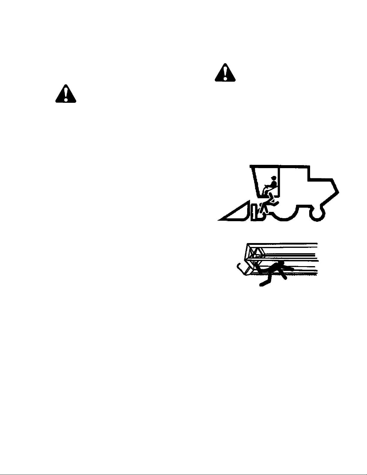
7.2.1 Header Lift Cylinder Locks
DANGER
To avoid bodily injury or death from fall of
raised machine, always engage lift
cylinder stops before going under header
for any reason. See your Combine
Operator’s Manual for instructions for use
and storage of header lift cylinder stops
7.2.2 Reel Props
WARNING
To avoid bodily injury from fall of raised
reel, always engage reel props before
going under raised reel for any reason.
IMPORTANT
To prevent damage to reel support
arms, do not transport header with
reel props engaged.
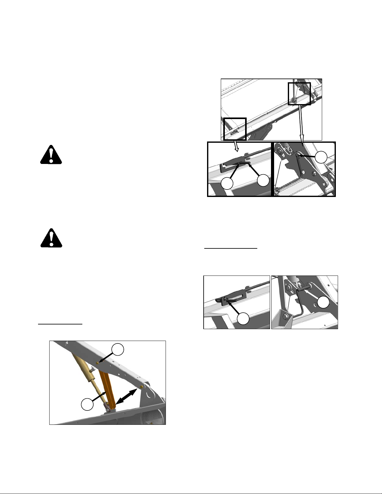
Reel props are located at the reel support arms.
Engage Props:
NOTE
Keep pivot bolt (B) properly tightened
so prop remains in stored position
when not in use, yet can be engaged
with hand force.
D
E
c. At center arm, use handle (C) to move lock rod
to inboard position (E), engaging pin (D) into
lock in arm.
d. Lower reel until props contact cylinder mounts
on outer reel arms, and pin at center arm.
Disengage Props:
a. Raise reel to maximum height.
b. At outer arms, push props (A) back inside arms.
F
C
C
a. Raise reel to maximum height.
B
A
b. At outer arms, move props (A) to engaged
position (shown).
169593 24 Revision B
c. At center arm, use handle (C) to move lock rod
to outboard position (F).
Page 27
SECTION 7. OPERATION
7.2.3 Endshields
Headers are fitted with a hinged polyethylene
endshield on both ends of the header.
7.2.3.1 Opening
C
B
A
F
E
D
NOTE
If more access is required to front of
drives area, carefully disengage front
of shield from tab (E), and swing front
of shield away from header.
IMPORTANT
Do NOT force shield once it has
reached its end of travel as damage to
the shield structure can occur.
NOTE
If complete access to the endsheet
area is required, the shield can be
removed. See Section 7.2.3.3
Removing (below).
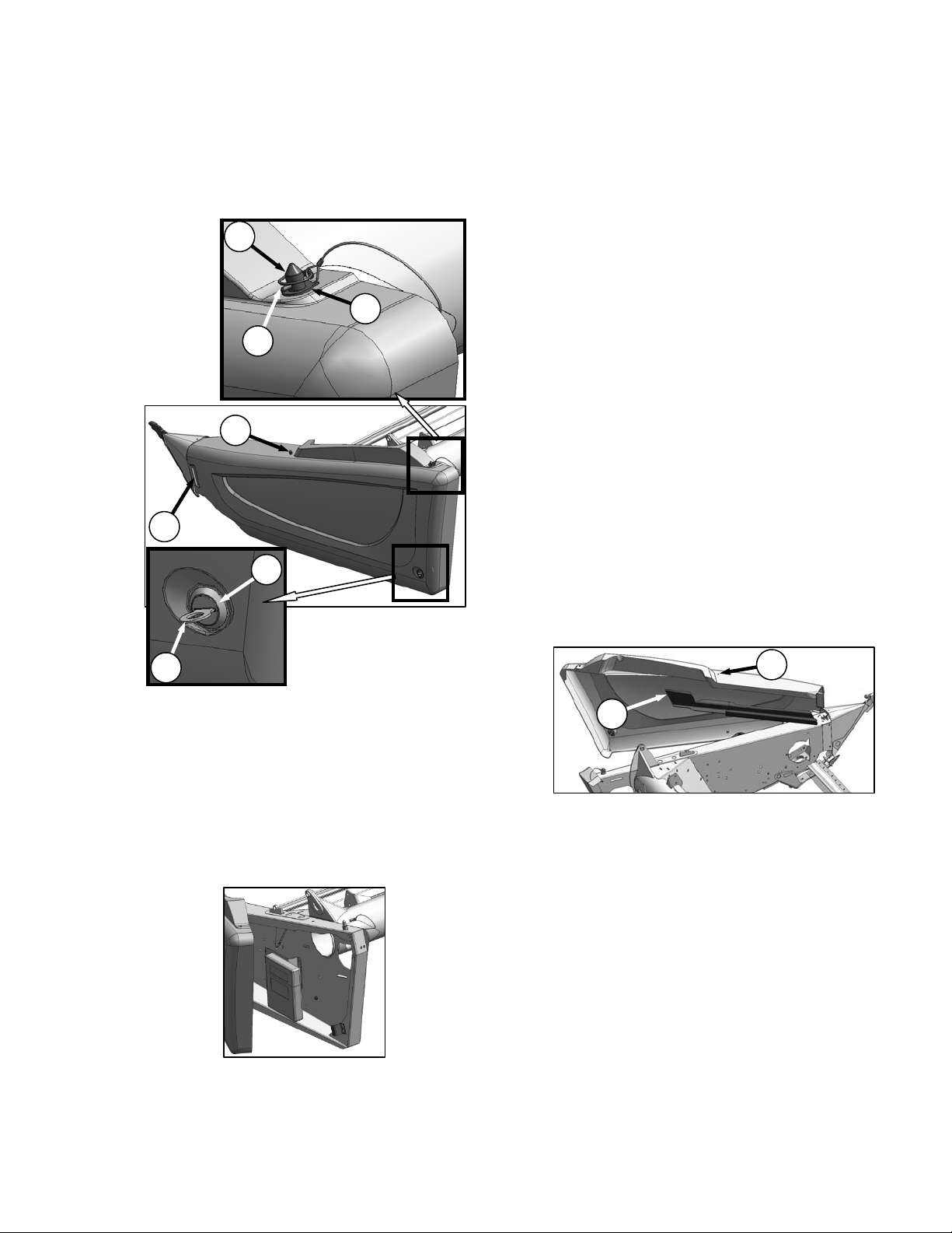
7.2.3.2 Closing
a. Maintain forward pressure and swing rear of
shield towards header.
b. Lift shield, and engage pin (C) on top of frame
endsheet.
c. Push in shield to engage lower latch (D).
d. Use tool (B) to lock lower latch (D).
e. Replace tool (B) and lynch pin (A) on top pin
(C).
7.2.3.3 Removing
a. Open endshield. See Section 7.2.3.1 Opening
(in previous column).
B
a. Remove lynch pin (A), and tool (B) from pin (C)
at top rear of endshield.
b. Use tool (B) to unlock latch (D) at lower rear
corner of endshield.
c. Lift shield at aft end to clear pin (C).
d. Swing shield out and away from header while
maintaining forward pressure to prevent shield
from slipping out of tab (E) at front of endsheet.
IMPORTANT
Shield is designed to open sufficiently
for normal access to the drive system
and manual case as shown.
F
G
b. Remove acorn nut (F), and lift endshield off
support (G)
.
169593 25 Revision B
Page 28
SECTION 7. OPERATION
7.2.3.4 Installing
G
G
H
a. Position endshield on endshield support (G),
and locate hole on the stud (H).
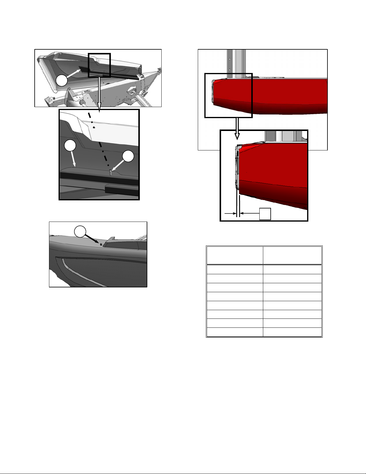
7.2.3.5 Adjustment
X
F
b. Secure endshield with acorn nut (F).
c. Close endshield. See Section 7.2.3.2 Closing
(on previous page).
NOTE
Plastic endshields are subject to
expansion or contraction depending
on large temperature variations. Top
pin and lower latch bracket positions
can be adjusted to compensate for
dimensional changes. Refer to next
section.
a. Check gap ‘X’ between the front end of shield
and header frame, and compare to chart below.
TEMPERATURE
Degrees ˚F (˚C)
25 (-4) 1-1/8 (28)
45 (7) 1 (24)
65 (18) 13/16 (20)
85 (29) 5/8 (16)
105 (41) 1/2 (12)
125 (52) 5/16 (8)
145 (63) 3/16 (4)
165 (89) 0
GAP ‘X’
Inches (mm)
(continued next page)
169593 26 Revision B
Page 29
SECTION 7. OPERATION
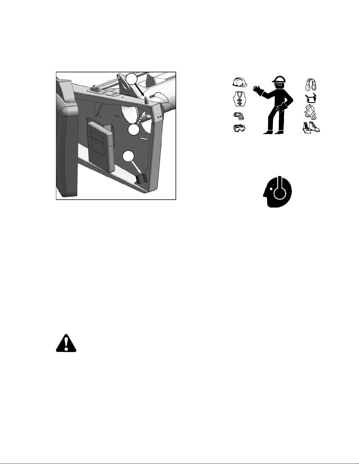
b. If adjustments are required, proceed as follows:
1. Open endshield. See Section 7.2.3.1
Opening.
B
A
C
As well, carry with you any protective
clothing and personal safety devices
that COULD be necessary through the
day. Don't take chances.
You may need:
o a hard hat
o protective glasses or goggles
o heavy gloves
o respirator or filter mask
o wet weather gear
2. From inside endsheet, loosen nut (A) on
pin (B) with a 3/4 inch socket.
3. Close endshield, and adjust position to
achieve the gap ‘X’ between the front end
of shield and header frame. (on previous
page).
4. Open endshield, and tighten nut (A).
5. To achieve a snug fit between top of shield
and header frame, and to ensure that
endshield is fully engaged on pin (B),
loosen bolts on catch (C), and adjust catch
as required to re-position shield.
6. Tighten bolts on catch (C).
7. Close endshield.
7.2.4 Daily Start-Up Check
Do the following each day before start-up:
CAUTION
Clear the area of other persons, pets etc.
Keep children away from machinery.
Walk around the machine to be sure no
one is under, on, or close to it.
Wear close fitting clothing and
protective shoes with slip resistant
soles.
Remove foreign objects from the
machine and surrounding area.
o Protect against noise. Wear a
suitable hearing protective device
such as ear muffs or ear plugs to
protect against objectionable or
uncomfortable loud noises.
a. Check the machine for leaks or any parts that
are missing, broken, or not working correctly.
NOTE:
Use proper procedure when searching
for pressurized fluid leaks. Refer to
Section 8.5 HYDRAULICS.
b. Clean all lights and reflective surfaces on the
machine.
c. Perform all Daily maintenance. Refer to Section
8.4.1 Maintenance Schedule/Record.
169593 27 Revision B
Page 30
SECTION 7. OPERATION
7.3 HEADER ATTACHMENT /
DETACHMENT
The header/adapter is configured to each
particular model of combine at the factory.
These combines are:
COMBINE SECTION
Case IH 7010, 8010, 7120,
8120, 5088, 6088, 7088
John Deere 60, 70 and
S Series
CAT Lexion 500, 700
(R Series)
New Holland CR, CX
AGCO Gleaner R, S Series
Challenger 660, 670, 680B
Massey 9690, 9790, 9895
This section includes instructions on setting up,
attaching, and detaching the header to the
combines listed above.
IMPORTANT
Ensure applicable functions (AHHC,
Draper Header Option, Hydraulic
Center-Link Option, Hydraulic Reel
Drive, etc.) are enabled on the
combine and in the combine
computer. Failure to do so may
result in improper header operation.
7.3.1 Adapter Set-up
7.3.2
7.3.3
7.3.4
7.3.5
7.3.6
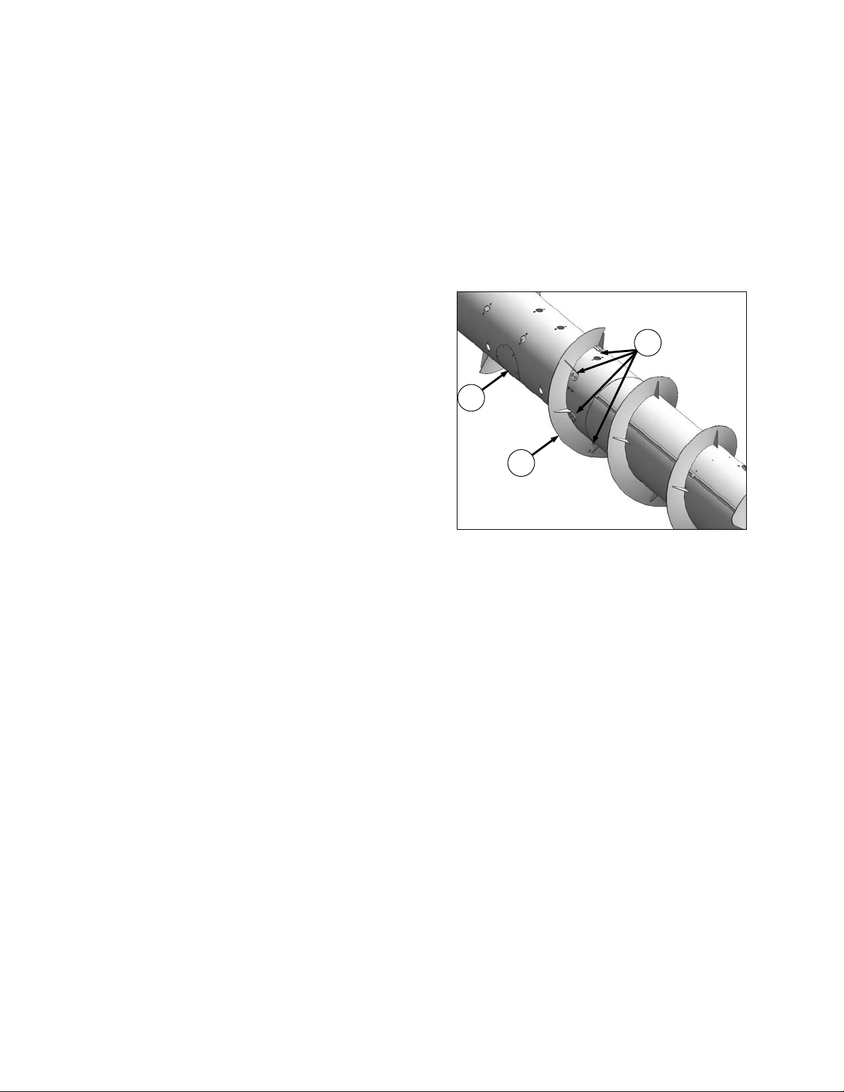
7.3.1.1 Flighting Extensions
Flighting extension kits may have been supplied
with your header to improve feeding in certain
crops such as rice. Installation instructions are
included with the kits.
They are not recommended in cereal crops.
APPLICABLE COMBINES: All except New
Holland CR960, 9060, 970, 9070, and 9080.
If necessary, remove auger flighting extensions
as follows:
B
A
C
a. Remove access cover (A).
b. Remove eight bolts (B), washers, and nuts that
secure flighting extension (C) to auger and
remove extension.
c. Repeat for other flighting extension.
d. Re-install access cover (A).
The following sections outline recommended
adapter set-up guidelines, depending on your
combine and crop.
The recommendations cannot cover all
conditions.
If feeding problems develop with adapter
operation. For detailed information, refer to
Section 9 TROUBLESHOOTING.
169593 28 Revision B
Page 31

SECTION 7. OPERATION
7.3.1.2 Stripper Bars
Stripper bar kits may have been supplied with
your header to improve feeding in certain crops
such as rice. Installation instructions are
included with the kits.
They are not recommended in cereal crops.
APPLICABLE COMBINES: All except New
Holland CR960, 9060, 970, 9070, and 9080.
If necessary, remove auger stripper bars as
follows:
B
A
7.3.1.3 Auger Drive
The adapter auger is chain driven from a
sprocket that is mounted on the input shaft from
the combine, and which is enclosed in the drive
gearbox.
The speed is determined by the combine input
shaft, and is matched to each particular
combine, so no adjustment is necessary.
However, optional drive sprockets are available
to change the auger speed to optimize auger
performance. See your MacDon Dealer.
NOTE
For special conditions, 20T, 22T, and
26T sprockets are available to change
adapter feed auger speed. Consult
with your MacDon Dealer.
a. Remove four bolts (A) and nuts securing bars
(B) to adapter frame and remove bars.
b. Repeat for opposite set of stripper bars.
169593 29 Revision B
Page 32

SECTION 7. OPERATION
7.3.1.4 CR Feeder Deflectors
For New Holland CR 960, 9070, and 9080
combines, feeder kits have been installed on
the adapter at the factory to improve feeding
into the feeder house.
They may also have been installed as an option
on older machines. If necessary, they can be
removed.
CA25 adapters for the CR Models listed have
short feeder kits installed at the factory. Long
feeder kits are provided for narrow feeder
house combines, and are dealer-installed to
replace the short feeder kits.
A
B
LH SHOWN - RH OPPOSITE
COMBINE
MODEL
CR970,
9070, 9080
CR960,
9060, 940,
9040
FEEDER
HOUSE SIZE
Wide
Narrow
FEEDER KIT SIZE
Short: 7-7/8 in.
(200 mm)
Long: 12-13/16 in.
(325 mm)
If required, replace the feeder deflectors as
follows:
A
b. Remove two bolts (B), and nuts securing
deflector (A) to adapter frame and remove
deflector.
c. Position replacement deflector, and secure with
bolts (B) and nuts. Maintain dimension ’X’ from
existing deflector for replacement deflector.
d. Repeat for opposite deflector.
e. After attaching header to combine, extend
center-link fully, and check gap ’X’ between
deflector and pan.
f. Maintain 7/8 +/- 1/8 in. (22 +/- 3 mm).
X
a. Determine position of existing deflector (A) by
measuring gap ‘X’ between deflector forward
edge and pan.
169593 30 Revision B
Page 33

SECTION 7. OPERATION - CASE IH
7.3.2 Case IH 7010, 8010, 7120, 8120, 5088,
6088, 7088
7.3.2.1 Attachment
c. Lift lever (C) on adapter at left side of feeder
house, and push handle (D) on combine to
engage locks (E) on both sides of the feeder
house.
d. Push down on lever (C) so that slot in lever
engages handle to lock handle in place.
e. If lock (E) does not fully engage pin on adapter
when (C) and (D) are engaged, loosen bolts
(F), and adjust lock as required. Re-tighten
bolts.
f. Connect combine hydraulic quick coupler to
receptacle (G) on adapter as follows:
A
a. Slowly drive combine up to adapter until feeder
house saddle (A) is directly under the adapter
top cross member (B).
b. Raise feeder house slightly to lift adapter,
ensuring feeder saddle is properly engaged in
adapter frame.
B
CAUTION
Stop engine, and remove key from ignition
before leaving Operator's seat for any
reason. A child or even a pet could engage
an idling machine.
H
N
J
G
K
1. Open cover (H).
2. Push in lock button (J), and pull handle (K)
to full open position.
L
D
3. Remove coupler (L) from combine, and
C
E
F
169593 31 Revision B
clean mating surfaces.
M
(continued next page)
Page 34

SECTION 7. OPERATION - CASE IH
M
G
J
K
4. Position onto adapter receptacle (G), and
push handle (K) to engage coupler pins into
receptacle.
5. Push handle to closed position until lock
button (J) snaps out.
g. Remove cover on adapter electrical receptacle
(N).
h. Remove electrical connector (M) from storage
cup on combine, and route to adapter
receptacle.
i. Align lugs on connector with slots in receptacle,
push connector onto receptacle, and turn collar
on connector to lock it in place.
P
Q
k. Pull back collar (P) on end of driveline, and
push onto combine output shaft (Q) until collar
locks.
R
LOCK
UNLOCK
S
l. Disengage both adapter float locks by moving
latch (R) away from adapter, and moving lever
(S) at each lock to lowest position.
O
j. Rotate disc (O) on adapter driveline storage
hook, and remove driveline from hook.
169593 32 Revision B
Page 35

SECTION 7. OPERATION - CASE IH
7.3.2.2 Detachment
a. Choose a level area. Position header slightly
above ground. Stop engine, and remove key.
DANGER
To avoid bodily injury or death from fall of
raised machine, always engage lift
cylinder stops before going under header
for any reason. See your Combine
Operator’s Manual for instructions for use
and storage of header lift cylinder stops.
IMPORTANT
If stabilizer wheels are installed, set
wheels to storage or uppermost
working position. Otherwise header
may tilt forward so that
re-attachment will be difficult. Refer
to Section 7.9.1 Cutting Height.
CAUTION
Stop engine, and remove key from ignition
before leaving Operator's seat for any
reason. A child or even a pet could engage
an idling machine.
LOCK
UNLOCK
b. Engage both adapter float locks by lifting lever
(A) at each lock until it latches into lock position.
IMPORTANT
If slow speed transport wheels are
installed, header may be detached
in either Transport or Field mode.
A
B
D
C
c. Disconnect driveshaft (B) from combine, and
slide driveshaft in hook (C) so that disc (D)
drops to secure driveshaft.
H
E
J
If detaching with wheel in Field
mode, set wheels to storage or
uppermost working position. Refer
to Section 7.9.1 Cutting Height.
169593 33 Revision B
d. Remove electrical connector (E), and replace
cover.
(continued next page)
Page 36

H
SECTION 7. OPERATION - CASE IH
M
E
F
G
e. Push in lock button (F), and pull handle (G) to
release coupler (H). Position coupler (H) onto
storage plate (J) on combine.
f. Place electrical connector (E) in storage cup on
plate on combine (J).
K
N
L
h. Lift lever (L), pull and lower handle (M) to
disengage feeder house/adapter lock (N).
i. Lower feeder house until it disengages adapter
support.
j. Slowly back combine away from adapter.
F
G
g. Push handle (G) to closed pos
button
(F) snaps out. Close cover (K).
ition until lock
169593 34 Revision B
Page 37

SECTION 7. OPERATION - JOHN DEERE 60, 70, and S SERIES
7.3.3 John Deere 60, 70, and S Series
Contour Master, Level Land
7.3.3.1 Attachment
C
D
B
A
B
f. Check that bolts (E) on adapter brackets are
tight.
g. If pins (B) do not fully engage adapter brackets,
loosen bolts (E), and adjust bracket as required.
Re-tighten bolts.
h. Remove blocks from under cutterbar.
i. Start engine, and lower header.
E
a. Push handle (A) on combine coupler toward
feeder house to retract pins (B) at bottom
corners of feeder house.
b. Slowly drive combine up to adapter until feeder
house saddle (C) is directly under the adapter
top cross member (D).
c. Raise feeder house to lift adapter, ensuring
feeder saddle is properly engaged in adapter
frame.
d. Raise or lower header until slightly off the
ground.
CAUTION
Stop engine, and remove key from ignition
before leaving Operator's seat for any
reason. A child or even a pet could engage
an idling machine.
A
G
F
j. Pull handle (F) on adapter to release coupler
(G) from storage position. Remove coupler,
and push handle back into adapter to store.
k. Attach coupler (G) to combine as follows:
A
B
e. Pull handle (A) to engage pins (B) in adapter.
169593 35 Revision B
1. Handle (A) should be in the nearly-up
position. Clean receptacle.
(continued next page)
Page 38

SECTION 7. OPERATION - JOHN DEERE 60, 70, and S SERIES
H
L
G
J
K
A
2. Locate coupler (G) onto receptacle, and
pull handle (A) so that lugs on coupler are
engaged into handle.
3. Pull handle to full horizontal position as
shown.
4. Slide latch (H) to lock handle in position,
and secure with lynch pin (J).
5. If adapter is equipped with reel
fore-aft / header tilt selector, connect
harness (K) to combine connector (L).
P
LOCK
Q
UNLOCK
n. Disengage both adapter float locks by moving
latch (P) away from adapter, and moving lever
(Q) at each lock to lowest position.
M
l. Rotate disc (M) on adapter driveline storage
hook, and remove driveline from hook.
O
N
m. Pull back collar (N) on end of driveline, and
push onto combine output shaft (O) until collar
locks.
169593 36 Revision B
Page 39

SECTION 7. OPERATION - JOHN DEERE 60, 70, and S SERIES
7.3.3.2 Detachment
a. Choose a level area. Position header slightly
above ground. Stop engine, and remove key.
DANGER
To avoid bodily injury or death from fall of
raised machine, always engage lift
cylinder stops before going under header
for any reason. See your Combine
Operator’s Manual for instructions for use
and storage of header lift cylinder stops.
CAUTION
IMPORTANT
If stabilizer wheels are installed, set
wheels to storage or uppermost
working position. Otherwise header
may tilt forward so that
re-attachment will be difficult. Refer
to Section 7.9.1 Cutting Height.
B
C
Stop engine, and remove key from ignition
before leaving Operator's seat for any
reason. A child or even a pet could engage
an idling machine.
LOCK
A
UNLOCK
b. Engage both adapter float locks by lifting lever
(A) at each lock until it latches into the lock
position.
IMPORTANT
If slow speed transport wheels are
installed, header may be detached
in either Transport or Field mode.
c. Open shield (B) on combine. Pull back collar
on driveline, and pull driveline (C) off combine
output shaft.
E
D
d. Slide driveline in hook (D) so that disc (E) drops
to secure driveline.
If detaching with wheel in Field
mode, set wheels to storage or
uppermost working position.
Otherwise header may tilt forward
so that re-attachment will be difficult.
Refer to Section 7.9.1 Cutting
Height.
169593 37 Revision B
e. Lift handle (F) on adapter.
F
(continued next page)
Page 40

SECTION 7. OPERATION - JOHN DEERE 60, 70, and S SERIES
f. Disconnect hydraulic/electrical coupler from
combine as follows:
J
G
H
P
K
K
1. Disconnect harness (P) from combine
harness.
2. Remove lynch pin (H), and slide lock (J) to
release handle (K).
K
G
3. Lift handle (K) to full vertical position to
release coupler (G) from combine.
L
5. Push handle (K) on combine toward feeder
house to disengage feeder house pin (L)
from adapter.
N
M
g. Lower feeder house until saddle (M)
disengages and clears adapter support (N).
h. Slowly back combine away from adapter.
G
F
4. Position coupler (G) on adapter receptacle,
and lower handle (F) to lock coupler.
169593 38 Revision B
Page 41

SECTION 7. OPERATION - CAT LEXION
7.3.4 CAT Lexion 500, 700 Series
7.3.4.1 Attachment
A
B
a. Handle (A) on the CA25 adapter should be in
raised position, and pins (B) at bottom corners
of adapter retracted.
b. Slowly drive combine up to adapter until feeder
house is directly under the adapter top cross
member.
CAUTION
Stop engine, and remove key from ignition
before leaving Operator's seat for any
reason. A child or even a pet could engage
an idling machine.
B
E
e. Remove locking pin (E) from adapter pin (B).
A
B
E
D
C
D
C
c. Raise feeder house to lift adapter, ensuring
feeder house posts (C) are properly engaged in
adapter frame (D).
d. Position header slightly off the ground.
f. Lower handle (A) to engage adapter pins (B)
into feeder house. Re-insert locking pin (E),
and secure with hairpin.
(continued next page)
169593 39 Revision B
Page 42

SECTION 7. OPERATION - CAT LEXION
g. Connect hydraulic hoses as follows:
G
F
J
1. Unscrew knob (F) on combine coupler (G)
to release coupler from combine
receptacle.
J
2. Remove cover (J) from adapter receptacle.
K
L
F
h. Place cover (J) on combine receptacle.
N
i. Rotate disc (N) on adapter driveline storage
hook, and remove driveline from hook.
O
M
G
3. Clean mating surface of coupler (G), and
locate onto adapter receptacle (K).
4. Turn knob (F) to secure coupler to
receptacle.
5. Connect combine harness (L) to reel
fore-aft/header tilt selector receptacle (M).
169593 40 Revision B
j. Attach driveline to combine output shaft (O).
(continued next page)
Page 43

P
SECTION 7. OPERATION - CAT LEXION
b. Engage the adapter float locks by lifting lever
(A) at both locks until it latches into the lock
position.
IMPORTANT
If slow speed transport wheels are
installed, header may be detached
in either Transport or Field mode.
LOCK
Q
UNLOCK
k. Disengage both adapter float locks by moving
latch (P) away from adapter, and moving lever
(Q) at each lock to lowest position.
7.3.4.2 Detachment
a. Choose a level area. Position header slightly
off the ground. Stop engine, and remove key.
DANGER
To avoid bodily injury or death from fall of
raised machine, always engage lift
cylinder stops before going under header
for any reason. See your Combine
Operator’s Manual for instructions for use
and storage of header lift cylinder stops.
If detaching with wheel in Field
mode, set wheels to storage or
uppermost working position.
Otherwise header may tilt forward
so that re-attachment will be difficult.
Refer to Section 7.9.1 Cutting
Height.
IMPORTANT
If stabilizer wheels are installed, set
wheels to storage or uppermost
working position. Otherwise header
may tilt forward so that
re-attachment will be difficult. Refer
to Section 7.9.1 Cutting Height.
B
CAUTION
c. Disconnect driveline (B) from combine.
Stop engine, and remove key from ignition
before leaving Operator's seat for any
reason. A child or even a pet could engage
an idling machine.
D
C
LOCK
A
d. Slide driveline in hook (C) so that disc (D) drops
to secure driveline.
UNLOCK
169593 41 Revision B
(continued next page)
Page 44

SECTION 7. OPERATION - CAT LEXION
e. Disconnect hydraulics/electrical from adapter as
follows:
G
1. Unplug electrical connector (E) from
adapter receptacle.
2. Unscrew knob (F) on coupler (G) to release
coupler from adapter.
F
E
H
5. Place cover (H) on adapter receptacle.
L
K
H
3. Remove cover (H) from combine
receptacle.
F
G
4. Locate coupler (G) onto combine
receptacle, and turn knob (F) to secure
coupler to receptacle.
J
f. Remove locking pin (J) from adapter pin (K).
g. Raise handle (L) to disengage adapter pins (K)
from feeder house. Replace locking pin (J) in
adapter pin, and secure with hairpin.
N
M
h. Lower feeder house to ground until feeder
house posts (M) disengage adapter (N).
i. Slowly back combine away from adapter.
169593 42 Revision B
Page 45

SECTION 7. OPERATION - NEW HOLLAND CR, CX
7.3.5 New Holland CR, CX
7.3.5.1 Attachment
B
A
a. Ensure handle (A) is positioned so that hooks
(B) can engage adapter.
A
B
F
E
G
d. Lift lever (E) on adapter at left side of feeder
house, and push handle (A) on combine so that
hooks (B) engage pins (F) on both sides of the
feeder house.
e. Push down on lever (E) so that slot in lever
engages handle to lock handle in place.
f. If hook (B) does not
fully engage pin on adapter
when (A) and (E) are engaged, loosen bolts
(G), and adjust lock as required. Re-tighten
bolts.
C
D
b. Slowly drive combine up to adapter until feeder
house saddle (C) is directly under the adapter
top cross member (D).
c. Raise feeder house to lift adapter, ensuring
feeder saddle is properly engaged in adapter
frame.
CAUTION
Stop engine, and remove key from ignition
before leaving Operator's seat for any
reason. A child or even a pet could engage
an idling machine.
J
K
L
g. Open cover (J).
h. Push in lock button (K), and pull handle (L)
halfway up to open position.
(continued next page)
169593 43 Revision B
Page 46

SECTION 7. OPERATON - NEW HOLLAND CR, CX
N
H
i. Remove hydraulic quick coupler (H) from
storage plate on combine, and clean mating
surface of coupler.
N
H
K
L
j. Position coupler (H) onto adapter receptacle,
and push handle (L) to engage pins into
receptacle.
k. Push handle (L) to closed position until lock
button (K) snaps out.
l. Remove cover on adapter electrical receptacle.
m. Remove connector (N) from combine.
n. Align lugs on connector (N) with slots in adapter
receptacle, and push connector onto
receptacle. Turn collar on connector to lock it in
place.
P
o. Rotate disc (P) on adapter driveline storage
hook, and remove driveline from hook.
Q
p. Pull back collar on end of driveline, and push
onto combine output shaft (Q) until collar locks.
R
LOCK
S
UNLOCK
q. Disengage both adapter float locks by moving
latch (R) away from adapter, and moving lever
(S) at each lock to lowest position.
169593 44 Revision B
Page 47

SECTION 7. OPERATION - NEW HOLLAND CR, CX
7.3.5.2 Detachment
a. Choose a level area. Position header slightly
off the ground. Stop engine, and remove key.
IMPORTANT
If stabilizer wheels are installed, set
wheels to storage or uppermost
working position. Otherwise header
may tilt forward so that
re-attachment will be difficult. Refer
to Section 7.9.1 Cutting Height.
DANGER
To avoid bodily injury or death from fall of
raised machine, always engage lift
cylinder stops before going under header
for any reason. See your Combine
Operator’s Manual for instructions for use
and storage of header lift cylinder stops.
CAUTION
Stop engine, and remove key from ignition
before leaving Operator's seat for any
reason. A child or even a pet could engage
an idling machine.
LOCK
A
B
B
D
C
c. Disconnect driveshaft (B) from combine, and
slide driveshaft in hook (C) so that disc (D)
drops to secure driveshaft.
E
K
UNLOCK
b. Engage the adapter float locks by lifting lever
(A) at each lock until it latches into the lock
position.
IMPORTANT
If slow speed transport wheels are
installed, header may be detached
in either Transport or Field mode.
If detaching with wheel in Field
mode, set wheels to storage or
uppermost working position.
Otherwise header may tilt forward
so that re-attachment will be difficult.
Refer to Section 7.9.1 Cutting
Height.
169593 45 Revision B
d. Remove hydraulic quick coupler (E) from
F
G
receptacle on adapter as follows:
1. Push in lock button (F), and pull handle (G)
to release coupler (E).
(continued next page)
Page 48

SECTION 7. OPERATON - NEW HOLLAND CR, CX
H
M
F
G
2. Push handle (G) to closed position until
lock button (F) snaps out. Close cover (H).
J
L
E
3. Position coupler (E) onto storage plate (J)
on combine.
e. Remove electrical connector (K) from adapter,
and connect to combine at (L). Replace cover
(M) on adapter receptacle.
Q
R
g. Lower feeder house until feeder house (Q)
disengages adapter support (R).
h. Slowly back combine away from adapter.
O
P
N
f. Lift lever (N), and pull and lower handle (O) to
disengage feeder house/adapter lock (P).
169593 46 Revision B
Page 49

SECTION 7. OPERATON - AGCO
7.3.6 AGCO
Gleaner R and S Series
Challenger 660, 670, 680B
Massey 9690, 9790, 9895
7.3.6.1 Attachment
ALL EXCEPT GLEANER ‘R’ & ‘S’ SERIES
A
ALL EXCEPT GLEANER ‘R’ & ‘S’ SERIES
and ‘LL’ MODEL
D
GLEANER ‘R’ & ‘S’ SERIES
D
B
‘LL’ MODEL
GLEANER ‘R’ & ‘S’ SERIES
B
A
a. Retract lugs (A) at base of feeder-house with
lock handle (B).
D
C
E
b. Slowly drive combine up to adapter until feeder
house is directly under the adapter top cross
member (C), and alignment pins (D) are aligned
with holes (E) in adapter frame.
(continued next page)
169593 47 Revision B
Page 50

SECTION 7. OPERATION - AGCO
F
c. Raise feeder house to lift adapter, ensuring
feeder house saddle (F) and alignment pins are
properly engaged in adapter frame.
d. Raise header slightly off the ground.
CAUTION
f. Connect adapter hydraulic quick coupler to
combine receptacle as follows:
G
H
1. Raise handle (G) to release coupler (H)
from adapter.
Stop engine, and remove key from ignition
before leaving Operator's seat for any
reason. A child or even a pet could engage
an idling machine.
ALL EXCEPT GLEANER ‘R’ & ‘S’ SERIES
A
GLEANER ‘R’ & ‘S’ SERIES
B
B
K
2. Push handle (J) on combine to full open
position.
3. Clean mating surfaces of coupler and
receptacle if necessary.
M
L
J
J
A
4. Position coupler (H) onto combine
receptacle (K), and pull handle (J) to fully
engage coupler into receptacle.
e. Engage lugs (A) with adapter using lock handle
(B).
169593 48 Revision B
5. Connect reel fore-aft/header tilt selector
harness (L) to combine harness (M).
(continued next page)
H
Page 51

SECTION 7. OPERATON - AGCO
N
g. Rotate disc (N) on adapter driveline storage
hook, and remove driveline from hook.
O
P
h. Pull back collar (O) on end of driveline, and
push onto combine output shaft (P) until collar
locks.
Q
LOCK
R
UNLOCK
i. Disengage both adapter flo
at locks by moving
latch (Q) away from adapter, and moving lever
(R) at each lock to lowest position.
169593 49 Revision B
Page 52

SECTION 7. OPERATION - AGCO
7.3.6.2 Detachment
a. Choose a level area. Position header slightly
off the ground. Stop engine, and remove key
IMPORTANT
If stabilizer wheels are installed, set
wheels to storage or uppermost
working position. Otherwise header
may tilt forward so that
re-attachment will be difficult. Refer
to Section 7.9.1 Cutting Height.
DANGER
To avoid bodily injury or death from fall of
raised machine, always engage lift
cylinder stops before going under header
for any reason. See your Combine
Operator’s Manual for instructions for use
and storage of header lift cylinder stops.
CAUTION
Stop engine, and remove key from ignition
before leaving Operator's seat for any
reason. A child or even a pet could engage
an idling machine.
LOCK
A
B
D
C
c. Disconnect driveshaft (B) from combine, and
slide driveshaft in hook (C) so that disc (D)
drops to secure driveshaft.
UNLOCK
E
b. Engage the adapter float locks by lifting lever
(A) at each lock until it latches into the lock
position.
IMPORTANT
If slow speed transport wheels are
installed, header may be detached
in either Transport or Field mode.
If detaching with wheel in Field
mode, set wheels to storage or
uppermost working position.
Otherwise header may tilt forward
so that re-attachment will be difficult.
Refer to Section 7.9.1 Cutting
Height.
169593 50 Revision B
d. Disconnect harness at connector (E).
e. Move handle (F) on combine multi-coupler to
full open position to release coupler (G) from
combine.
G
(continued next page)
F
Page 53

SECTION 7. OPERATON - AGCO
H
G
f. Raise handle (H) on adapter, and place coupler
(G) on adapter receptacle.
g. Lower handle (H) to lock coupler.
ALL EXCEPT GLEANER ‘R’ & ‘S’ SERIES
L
i. Lower feeder house until saddle (L) disengages
and clears adapter support.
j. Slowly back combine away from adapter.
J
GLEANER ‘R’ & ‘S’ SERIES
K
K
J
h. Retract lugs (J) at base of feeder-house with
lock handle (K).
169593 51 Revision B
Page 54

SECTION 7. OPERATION - ADAPTER
7.4 ATTACHING AND DETACHING
HEADER WITH ADAPTER
Using this procedure, the adapter remains
attached to the combine, and is appropriate
when:
detaching the header for use on a
windrower,
changing headers, or
performing certain maintenance tasks.
The procedure is the same for all makes and
models of combines. The headers can be
attached to the adapter from either Field
configuration or Transport configuration.
7.4.1 Detaching
a. Disconnect adapter deck from cutterbar as
follows:
1. Start engine, and tilt header to almost full
forward position to increase clearance
under adapter feed draper.
2. Stop engine, and remove key.
WARNING
B
A
3. Remove two hex head bolts (A) attaching
filler (B) to transition pan at front corners,
and fold back filler (B) for access to latch
(C).
E
D
C
F
4. Rotate latch (C) down with a 15/16 wrench
on hex (D) so that bolt (E) can be removed.
5. Rotate latch (C) up and back to lower
adapter deck and disengage transition pan
Keep hands clear of the area between
guards and sickle at all times.
CAUTION
Wear heavy gloves when working around
or handling sickles.
169593 52 Revision B
tube (F).
6. Re-install bolt (E).
7. Repeat for other side of the feed draper
deck.
(continued next page)
Page 55

G
LOCK
SECTION 7. OPERATION - ADAPTER
NOTE
Stabilizer/Transport wheels can be
used to support header.
f. Disengage lift cylinder locks.
g. Start engine and lower header until it rests on
blocks (K) (or stabilizer wheels) and the ground.
NOTE
Length of hydraulic center-link may
need to be adjusted to relieve load on
link.
UNLOCK
b. Engage the adapter float locks by lifting lever
(G) until it latches into the lock position.
DANGER
To avoid bodily injury or death from fall of
raised machine, always engage lift
cylinder stops before going under header
for any reason. See your Combine
Operator’s Manual for instructions for use
and storage of header lift cylinder stops.
c. Disengage reel props, start engine, lower reel
and raise header fully. Stop engine, remove
key, and engage combine lift cylinder locks.
H
J
CAUTION
Stop engine, and remove key from ignition
before leaving Operator's seat for any
reason. A child or even a pet could engage
an idling machine.
h. Stop engine, and remove key from ignition.
i. Disconnect hydraulic ce nter-link:
L
M
1. Remove lynch pin and clevis pin (L), then
lift center-link (M) clear of bracket.
2. Replace pin (L), and secure with lynch pin.
(continued next page)
d. Remove ring (H) from pin (J), and remove pins
from header legs at delivery opening.
K
GROUND
e. Place two 6 inch (150 mm) blocks (K) under
header legs at delivery opening.
169593 53 Revision B
Page 56

P
SECTION 7. OPERATION - ADAPTER
j. Disconnect knife and draper drive hydraulic
hoses at bracket. Cap off ends immediately to
avoid loss of oil.
k. Store and secure hoses on adapter frame.
l. If quick disconnects are installed, disconnect as
follows:
O
N
1. Line up slot (N) in collar with pin (O) on
connector.
2. Push collar toward pin, and pull connector
to disengage.
3. Install plugs or caps on hose ends
(if equipped).
m. Disconnect electrical connector (P) by turning
collar counterclockwise, and pulling connector
to disengage.
n. Store and secure hoses and electrical
connector on adapter.
o. Disconnect reel hydraulics. Cap off end
immediately to avoid loss of oil.
p. Store and secure hoses to adapter frame.
q. Ensure header is on ground, or is supported by
wheels in Transport mode.
r. Start engine, and slowly back combine away
from header.
s. Stop engine, and remove key.
H
J
t. Replace pin (J) in header legs, and secure with
ring (H).
169593 54 Revision B
Page 57

SECTION 7. OPERATION - ADAPTER
7.4.2 Attaching
The D65 Harvest Header® can be attached to
the adapter from either Field configuration or
Transport configuration.
NOTE
Stabilizer/Transport wheels can be
used to support header. Refer to
Section 7.9.1 Cutting Height.
A
E
c. Ensure latches (E) at front corners of adapter
are rotated towards the rear of adapter.
CAUTION
Be sure all bystanders are clear of
machine before starting engine or
engaging any header drives.
B
a. Prop up hydraulic center-link (A) with pin or
equivalent tool at (B).
CAUTION
Stop engine, and remove key from ignition
before leaving Operator's seat for any
reason. A child or even a pet could engage
an idling machine.
C
G
d. Start engine, and lower combine feeder house
so that adapter arms (F) are aligned with
header legs (G).
e. Drive slowly forward, maintaining alignment
between adapter arms (F) and header legs (G).
f. Keep adapter arms (F) just under the legs (G)
to ensure adapter legs seat properly in the
header linkage supports at (H).
IMPORTANT
Keep hydraulic hoses clear to
prevent damage when driving into
header.
H
F
g. Continue forward until adapter arms (F) contact
D
b. Remove ring (C) from pin (D) and remove pins
from header legs at delivery opening.
169593 55 Revision B
stops in legs (G).
(continued next page)
Page 58

SECTION 7. OPERATION - ADAPTER
CAUTION
J
B
Always connect center-link before fully
raising header.
CAUTION
Be sure all bystanders are clear of
machine before starting engine or
A
engaging any header drives.
l. Start engine and raise adapter slowly, making
sure adapter legs engage in header legs.
m. Raise header fully, stop engine, and remove
key.
h. Adjust length of center-link (A) with header
angle hydraulics to approximately align eye (J)
on center-link with hole in header bracket.
i. Shut down engine, and remove key.
j. Connect center-link:
1. Pull pin (B) part way out of bracket, and
remove prop from under center-link (A).
B
A
2. Install pin (B) through center-link (A) and
bracket, and secure with lynch pin.
DANGER
To avoid bodily injury or death from fall of
raised machine, always engage lift
cylinder stops before going under header
for any reason. See your Combine
Operator’s Manual for instructions for use
and storage of header lift cylinder stops.
n. Engage header lift cylinder stops on combine.
C
D
o. Replace pin (D) in header legs, and secure with
ring (C).
p. Remove lift cylinder locks, start engine, and
lower header to ground. Adjust header angle to
the shallowest setting (shortest center-link).
(continued next page)
k. Connect reel hydraulics at right end of adapter
matching colored plastic ties.
169593 56 Revision B
Page 59

SECTION 7. OPERATION - ADAPTER
q. Raise reel fully, shut down engine, and remove
key from ignition.
r. Engage reel props.
WARNING
Keep hands clear of the area between
guards and sickle at all times.
s. Attach adapter feed deck:
E
4. Repeat for other side of feed draper deck.
N
O
t. Install fillers (N) at each front corner of feed
deck with two 3/8 inch x 0.75 long hex head
bolts (O)
at each location.
L
K
1. Remove bolts (K) at either side of opening
to allow attachment of adapter deck.
2. Rotate latches (E) forward and down
engage transition pan tube (L).
K
M
3. Rotate latches (E) down with a 15/16 in.
wrench on hex (M) to raise feed deck so
that bolt (K) can be re-installed to lock the
latch position.
E
P
u. Connect knife and draper drive hydraulics as
shown above, matching colored plastic cable
ties.
v. Attach electrical connector (P):
1. Remove cover on receptacle.
2. Align lugs on conne
receptacle, push connector onto receptacle
and turn collar on connector to lock it in
place.
3. Attach cover to mating cover on combine
wiring harness.
ctor with slots in
(continued next page)
169593 57 Revision B
Page 60

SECTION 7. OPERATION - ADAPTER
w. If quick disconnects are installed, connect as
follows:
1. Remove covers (if installed) from
receptacles and hose ends.
2. Check connectors and clean if required.
3. Push hose connector onto mating
receptacle until collar on receptacle snaps
into lock position.
NOTE
Ensure hoses are clear of driveline
and adjacent structure.
NOTE
It is not necessary to bleed the system
by loosening fittings.
x. Check float, and if the header is level. Refer to
Section 7.9.2 Header Float and Section 7.11
HEADER LEVELLING.
169593 58 Revision B
Page 61

SECTION 7. OPERATION
7.5 BREAK-IN PERIOD
a. After attaching header to combine for the first
time, operate the machine with reel drapers and
sickle running slowly for 5 minutes, watching
and listening FROM THE OPERATOR'S SEAT
for binding or interfering parts.
NOTE
Reel and side drapers will not operate
until oil flow fills the lines.
CAUTION
Before investigating an unusual sound or
attempting to correct a problem, shut off
engine, and remove key.
Until you become familiar with the
sound and feel of your new header, be
extra alert and attentive.
b. Perform the items specified in to Section 8.4.2
Break-In Inspections.
7.6 SHUTDOWN PROCEDURE
NOTE
7.7 HEADER CONTROLS
CAUTION
Be sure all bystanders are clear of
machine before starting engine or
engaging any header drives.
See your Combine Operator's Manual for
identification of in-cab controls for:
Header Drive Clutch
Header Height
Header Angle
Ground Speed
Reel Speed
Reel Height
Reel Fore-Aft Position
CAUTION
Before leaving the combine seat for any
reason:
Park on level ground if possible.
Lower the header fully.
Place all controls in NEUTRAL or PARK.
Disengage header drive.
Stop engine, and remove key from
ignition.
Wait for all movement to stop.
169593 59 Revision B
Page 62

SECTION 7. OPERATION
7.8 HEADER SET-UP
7.8.1 Header Settings
This table is a guideline for setting up the D65 Harvest Header ®. Settings other than those suggested can be
made to suit various crops and conditions not covered here. See also Section 7.8.2 Pickup Reel Settings.
Crop
Type
CerealsCanola
Soybeans Delta R i ce Californi a R i ce
Flax
Peas
Lentils
Stubble
Height
(in.)
0
4–8
10 +
4–8
10 +
0
4–8
10 +
2–6
8 +
0
2–6
0
0
Crop
Condition
Light
Normal
Heavy
Lodged
Light
Normal
Heavy
Lodged
Light
Normal
Heavy
Lodged
Light
Normal
Heavy
Lodged
Light
Normal
Heavy
Lodged
Light
Normal
Heavy
Lodged
Light
Normal
Heavy
Lodged
Light
Normal
Heavy
Lodged
Light
Normal
Heavy
Lodged
Light
Normal
Heavy
Lodged
Light
Normal
Heavy
Lodged
Light
Normal
Heavy
Lodged
Light
Normal
Heavy
Lodged
Light
Normal
Heavy
Lodged
Draper
Divider
Speed
Header Angle
Rods
Off 8 600–650 3 10–15
On
Off 525–600 3 or 4 5–10 4 or 5 Not Required
Off 8 B - C 600–650 4 10–15
Off D 525–600 3 or 4 5–10 4 or 5 Down Not Required
Off 8 600–650 4 10–15
On 2
Off 525–600 3 or 4 5–10 4 or 5
On
On
Whisker
(Note 6)
Whisker
(Note 5)
Whisker
(Note 5)
Off
Off
On
On
On
On
(Notes 1 and 4)
Setting
(Note 7)
7
7
7
7
8 Down
7 D 525–600 2 5–10 Center or Down
7
81 or 2
7 D 525–600 2 or 3 5–10
4
4
4
6
6
8 D 600–650 5–10
7
8 B - C 5–10
7
7
8 600–650 5–10
7
B - C
A 550–600On
A
B - C
A 600–650 2 5–10 Down
B - C
A 600–650 5–10
B - C
D 600–650 10–15 6 or 7
D 525–600 5–10
D 600–650 10–15
D 525–600 4 5–10
A 600–650 10–15
B - C 550–600
D 525–600 4 5–10
D 600–650 10–15
B - C 550–600
D 525–600 3 or 4 5–10 4 or 5
A 600–650 10–15
B - C
D 525–600 3 or 4 5–10 4 or 5
B - C
D 525–600 5–10
A
B - C
D 5–10 Down
B - C
D 525–600 5–10
B - C
D 525–600 5–10
Knife
Reel Cam
Speed
(Note 2)
Setting
2 or 3
2 or 3 6 or 7
Setting
550–600
550–600
550–600
550–600
550–600B - C
550–600B - C
550–600
550–600
600–650
600–650 5–10
550–600 10
550–600
Reel
Speed %
(Note 3)
2
2
2
3
3
210
2
2
26 or 7
Skid Shoe
Reel
Position
Position
6 or 7
102
Up or Center Storage
Stabilizer
(Note
Wheel
4)
4 and 5)
(Notes
Upper Cr o s s
Auger
Not Required
Recommended
Notes
Note 1:
Set header angle
as shallow as
6 or 7
10
Center or Down
Note 5
Not Required
Recommended
possible (setting A)
with center-link and
skid shoes while
maintaining cutting
height.
6 or 7
10
Note 5
Not RequiredNot Applicable
Note 2:
6 or 7
3 or 4
Center or Down
Note 5 Recommended
101
Minimum knife
drive pulley rpm.
Applicable onl y t o
single-knife
headers.
6 or 7
10
3 or 4
RecommendedNote 5Not Applicable
Note 3:
Percentage above
10
Up or Center Storage Not Required
4 or 5
ground speed.
Note 4:
10
6 or 7
Not RequiredNote 5Center or Down
Cutting height is
controlled with a
combination of skid
shoes and header
10
6 or 7
Not Applicable Note 5 Not Required
6 or 7
10
Not RequiredNote 5Center or Down
angle.
Note 5:
Stabilizer wheels
are used to limit
the side to side
movement when
cutting off the
10
Not Applicable Note 5
Not Required
ground in rolling
terrain, and to
minimize bouncing.
Not RequiredStorageUp or Center6 or 7
Note 6:
Available through
your Dealer Parts
6 or 7
Center or Down
Note 5 Not Required
10
Department.
Whis k er divider not
required on both
ends of header.
6 or 7
4 or 5
RecommendedStorageUp or Cent er
Note 7:
Setting on CA25
10
StorageUp or Cent er
Not Required
draper control.
169593 60 Revision B
Page 63

SECTION 7. OPERATION
7.8.2 Pickup Reel Settings
The following chart illustrates the profile of the reel at each cam or finger pitch setting as well as the reel
position relative to the ground at different positions on the reel arm. Refer to the chart in the previous
section for applicability of each finger pattern and reel position. See NOTES on the next page.
CAM SETTING NUMBER
(Finger Speed Gain)
1
(0)
2
(20%)
REEL POSITION
NUMBER
6 or 7
3 or 4
REEL FINGER PATTERN
3
6 or 7
(30%)
4
2 or 3
(35%)
169593 61 Revision B
Page 64

SECTION 7. OPERATION
NOTES:
a. Adjust reel forward to get closer to ground when tilting header back. Fingers/Tines will dig into ground
at extreme reel forward positions, so adjust skid shoes or header angle to compensate. Adjust reel
rearward to get reel further away from ground when tilting header forward.
b. Header Tilt can be increased to get reel closer to ground or decreased to get reel further away from
ground while keeping material flowing onto drapers.
c. To leave maximum amount of stubble behind in lodged crop, raise header but increase header tilt to
keep reel close to ground. Position the reel fully forward.
d. Reel may have to be moved back to prevent lumps or plugging on cutterbar in thinner crops.
e. Minimum crop carrying capacity (minimum area of exposed draper between reel and header backsheet)
occurs with the reel in the furthest aft position.
f. Maximum crop carrying capacity (maximum area of exposed draper between reel and header
backsheet) occurs with the reel in the furthest forward position.
g. The tip speed of the fingers/tines at the cutterbar becomes higher than the reel speed at higher cam
settings due the nature of the cam action. Refer to Reel Settings Chart on previous page.
169593 62 Revision B
Page 65

SECTION 7. OPERATION
7.9 HEADER OPERATING VARIABLES
Satisfactory function of the header in all
situations requires making proper adjustments
to suit various crops and conditions.
Correct operation reduces crop loss and allows
cutting of more acres. As well, proper
adjustments and timely maintenance will
increase the length of service you receive from
the machine.
The variables listed below and detailed on the
following pages will affect the performance of
the machine. You will quickly become adept at
adjusting the machine to give you the desired
results.
VARIABLE SECTION
Cutting Height
Header Float
Header Angle
Reel Speed
Ground Speed
Draper Speed
Knife Speed
Reel Height
Reel Fore-Aft Position
Reel Tine Pitch
Crop Divider Rods
7.9.1
7.9.2
7.9.3
7.9.4
7.9.5
7.9.6
7.9.7
7.9.8
7.9.9
7.9.10
7.9.11
The proper setting requires ‘balancing’ the
amount of header weight carried by the float
and the stabilizer wheels.
Refer to Section 7.8.1 Header Settings for
recommended use in specific crops and crop
conditions.
CAUTION
Stop engine, and remove key from ignition
before leaving Operator's seat for any
reason. A child or even a pet could engage
an idling machine.
a. Raise the header so that the stabilizer wheels
are off the ground. Shut down engine, and
remove the key.
b. Check that the float is working properly. See
Section 7.9.2 Header Float.
c. Set up the stabilizer wheels, if installed, as
follows: Otherwise, proceed to step d. on next
page.
CAUTION
Handle may be under tension, especially
when the wheels are on the ground. Raise
header so that wheels are off the ground
before making adjustments.
7.9.1 Cutting Height
Harvest Headers are designed to allow an
Operator to cut the crop above the ground for a
desired stubble height, or to cut the crop at
ground level with the header on the ground.
Cutting height will vary, depending on factors
including whether windrowing or straightcutting, type of crop, etc.
7.9.1.1 Cutting Off The Ground
Cutting height is controlled with a combination
of header lift cylinder adjustment and a
stabilizer wheel system, or a stabilizer/slow
speed transport wheel system.
The stabilizing wheel system in both options is
designed to minimize bouncing at the header
ends, and may be used to float the headers to
achieve an even cutting height when cutting
above ground level in cereal grains.
The system can provide very even stubble
height and greatly reduced operator fatigue.
C
A
B
LH SHOWN - RH OPPOSITE
1. Support wheel weight by lifting slightly with
one hand on handle B. Pull up on handle
(A) to release lock.
2. Lift wheel with handle (B) and engage
support channel into center slot (C) in
upper support.
3. Push down on handle (A) to lock.
(continued next page)
169593 63 Revision B
Page 66

SECTION 7. OPERATION
(
A
4. Lower header to desired cutting height
using combine controls, and check spring
length as shown. Re-adjust wheels as
required to achieve range.
IMPORTANT
Continuous operation with
excessive spring
compression
(i.e. spring length
shorter than
(11-5/8 in. [295 mm])
can result in damage to
suspension system.
d. Set up the stabilizer/slow speed
transport wheels, if installed, as follows:
Otherwise, proceed to step e.
1. Adjust right wheels as follows:
RELEASE
F
LOCK
12-5/8 in +/-1.0
320 mm +/-25)
G
E
2. Adjust left wheels as follows:
H
RELEASE
F
LOCK
i. Support wheel weight by lifting slightly
with one hand. Pull up on handle (F) to
release lock.
ii. Lift wheels to desired height, and
engage support channel into slot (H) in
upper support.
iii. Push down on handle (F) to lock.
D
iv. Lower header to desired cutting height
using combine controls, and check load
indicator as shown below. Re-adjust
wheels as required to achieve range
between 2 and 3 as shown below.
IMPORTANT
TRANSPORT TO FIELD - RH SIDE
i. Remove hairpin (D) from latch.
ii. Disengage latch (E) and lift right wheel
out of hook, and place on ground as
shown. This reduces weight of
assembly, and makes adjusting wheel
position easier.
iii. Support left wheel weight by lifting
slightly with one hand. Pull up on
handle (F) to release lock.
iv. Lift left wheel to desired height, and
engage support channel into slot (G) in
upper support.
v. Push down on handle (F) to lock.
vi. Lift right hand wheel back into field
position, and ensure latch (E) is
engaged.
vii. Secure latch with hairpin (D).
Continuous
operation with
excessive spring
compression
(i.e. load indicator
reading greater
than #4) can
result in damage
to suspension
system.
e. Adjust header angle to desired working angle
with the machine’s header angle controls. If
angle is not critical, set it to mid-position.
f. Use the combine AHHC to automatically
maintain cutting height. Refer to your combine
Operator’s Manual and AHHC instructions for
details.
NOTE
Header angle adjustments or AHHC
ground pressure control may be used
for ’on-the-go’ cut height adjustments.
169593 64 Revision B
Page 67

SECTION 7. OPERATION
7.9.1.2 Cutting On The Ground
Cutting on the ground is controlled with a
combination of skid shoes, header angle, and
float adjustment, and not with the header lift
cylinders.
NOTE
Skid shoes are standard equipment
on the D65 header.
Having the header ride on the skid shoes allows
the float linkage to float the header over
obstacles and follow ground contours, rather
than supporting the header with the cylinders.
Lowering the skid shoes or decreasing the
header angle increases the cutting height. This
may be desirable in stony conditions, to reduce
damage to cutting components. Also, a longer
stubble length helps material dry faster.
Raising the skid shoes and increasing the
header angle allows the crop to be shaved.
Refer to Section 7.8.1 Header Settings for
recommended skid shoe positions in specific
crops and crop conditions.
Set up the header as follows:
a. Fully raise the stabilizer wheels, or slow speed
transport wheels if installed. Refer to previous
section.
1. Remove lynch pin (A) at each skid shoe
(B).
2. Hold shoe, and remove pin (C) by
disengaging frame, and then pulling away
from shoe.
3. Raise or lower skid shoe to desired position
using holes in support as a guide.
4. Re-install pin (C), engage in frame, and
secure with lynch pin (A).
Inner Skid Shoes
E
1. Remove lynch pin (D).
2. Hold shoe (E), and remove pin (F) by
pulling down to disengage frame, and then
pulling away from shoe.
3. Raise or lower skid shoe (E) to desired
position using holes in support (G) as a
guide.
G
D
F
DANGER
To avoid bodily injury or death from
unexpected start-up or fall of raised
machine, stop engine, remove key, and
engage lift cylinder stops before going
under machine to adjust skid shoes or for
any reason.
b. Fully raise header, engage lift cylinder stops,
shut off engine and remove key.
c. Adjust skid shoes to achieve desired cutting
height as follows:
Outer Skid Shoes
A
C
B
D
F
4. Re-insert pin (F), engage in frame, and
secure with lynch pin (D).
d. Check that skid shoes are adjusted to the same
position.
e. Adjust header angle to desired working position
using the machine’s header angle controls. If
angle is not critical, set it to mid-position.
f. Check header float as described in the following
Section 7.9.2 Header Float.
169593 65 Revision B
Page 68

SECTION 7. OPERATION
7.9.2 Header Float
D65 combine headers perform best with
minimum extra weight on the header, under
normal conditions.
7.9.2.1 Header Float Locks
The function of the header float locks is to lock
and unlock the header float system. There are
two locks - one on each side of the adapter.
IMPORTANT
The float locks must be engaged
when the header is being
transported with the adapter
attached so there is no relative
movement between the adapter and
header during transport.
The float locks must also be locked
during detachment from the
combine to allow the feeder house
to release the adapter.
7.9.2.2 Checking and Adjusting Float
a. Park combine on level surface.
b. Fully lower the reel and adjust the fore-aft
position between 5 and 6 on decal on the right
side reel arm.
A
LOCK
B
UNLOCK
a. Disengage
float locks by moving latch (A)
downward, and moving lever (B) at each lock to
lowest position. In this position, the header is
unlocked, and can float with respect to the
adapter.
b. Engage
the float locks by moving lever (B) up
to its highest position. In this position, the
header cannot move with respect to the
adapter.
c. Adjust center-link to mid-range (between B and
C on cylinder indicator).
d. Position cutterbar 8–12 in. (200–300 mm) off
the ground.
CAUTION
Stop engine, and remove key from ignition
before leaving Operator's seat for any
reason. A child or even a pet could engage
an idling machine.
e. Stop engine, and remove key from ignition.
f. Check that adapter is level. If the adapter is not
level, perform the following checks prior to
adjusting the leveling linkages.
IMPORTANT
The adapter float springs are not
used to level the header.
Check combine tire pressures.
Check that the combine feeder house is
level. Refer to combine operator’s manual.
Check that top of adapter is level with
combine axle.
(continued next page)
169593 66 Revision B
Page 69

SECTION 7. OPERATION
D
B
UNLOCK
g. Move both header float lock levers (B) down
(UNLOCK).
h. If header is equipped with stabilizer wheels or
slow speed transport wheels, place them in
storage position.
D
F
E
RIGHT SIDE
j. Place torque wrench (D) onto float lock at (E).
Note position of wrench for checking RH or LH
side.
k. Push down on wrench to rotate bell crank (F)
forward.
G
i. Remove special torque wrench (D) from
storage position at RH side of adapter frame.
Pull slightly in direction shown to disengage
wrench from hook.
F
169593 67 Revision B
D
E
LEFT SIDE
l. Continue pushing down on the wrench until
indicator (G) reaches a maximum reading and
begins to decrease. Note the maximum
reading. Repeat for opposite side.
Use the table below as a guide for float
settings.
HEADER SIZE
(FT)
20, 25, 30
and 35 FT
40 and 45 FT 2 to 2-1/2 2-1/2 to 3
TORQUE SETTINGS
CUTTING ON
THE GROUND
1-1/2 to 2 2 to 2-1/2
CUTTING OFF
THE GROUND
(continued next page)
Page 70

SECTION 7. OPERATION
m. If reading on wrench is high, header is heavy.
If reading on wrench is low, header is light.
H
NOTE
If adequate header float cannot be
achieved using all of the available
adjustments, an optional heavy duty
spring is available. See your MacDon
Dealer or Parts Catalog for ordering
information.
J
LEFT SIDE FLOAT RIGHT SIDE FLOAT
n. To increase float (lighten header), turn bolts
(H) and (J) clockwise.
NOTE
Loosen jam nuts on adjuster bolts
before adjusting, and re-tighten once
complete.
o. To decrease float (increase header weight),
turn bolts (H) and (J) counterclockwise.
p. Use the following guidelines when adjusting
float:
1. For Single Knife Headers: Adjust the float
so the wrench reading is equal for both
sides.
2. For 40 and 45 ft. Double Knife Headers:
Adjust the float so that torque settings are
equal for both sides, and then loosen both
right side spring bolts two turns.
3. Turn each bolt pair equal amounts. After
adjustment has been made, repeat torque
wrench reading procedure.
4. To avoid frequent breakage of sickle
components, scooping soil, or soil build-up
at cutterbar in wet conditions, header float
should be set as light as possible without
causing excessive bouncing.
5. With a light float setting, it may be
necessary to use a slower ground speed to
avoid excessive bouncing and leaving a
ragged cut.
6. The stabilizer wheels may be used in
conjunction with float to minimize bouncing
at the header ends and control cut height
when cutting off the ground. Refer to
Section 7.9.1 Cutting Height for details.
7.9.2.3 Setting Feeder House Height and
Header Angle
L
K
a. Adjust feeder house height while watching float
indicator (K) to set cutterbar down force
(normally 2 on indicator). Lower feeder house
height to increase ground pressure (decrease
float). Indicator reading will increase.
NOTE
Installation of the auto header height
controller attachment is recommended
for cutting on the ground if the
combine is equipped to interface with
it.
b. When cutting on ground, adjust header angle to
achieve desired stubble height. Header angle
indicator (L) indicates A for shallowest
angle/higher stubble, and D for steepest
angle/lower stubble.
c. Decrease header angle to minimize pushing
soil.
NOTE
Header angle and reel fore-aft position
changes do not significantly affect
header float (downforce).
169593 68 Revision B
Page 71

SECTION 7. OPERATION
7.9.3 Header Angle
Header angle is the angle between the drapers
and the ground, and is adjustable to
accommodate crop conditions and/or soil type.
The following table summarizes the adjustment
range:
HEADER SIZE
(FT)
DRAPER
ANGLE
GUARD
ANGLE
SHORTEST CENTER-LINK
GUARD ANGLE
LONGEST CENTER-LINK
GUARD ANGLE
HEADER ANGLE
HEADER ANGLE
Guard angle is similar to header angle which is
the angle between the guard upper surface and
the ground. Refer to illustration above.
Flatter header angles are recommended for
normal crop conditions and for stony ground
because it minimizes sickle section breakage
and reduces soil scooping or build-up at the
cutterbar in wet conditions.
Steeper angles are recommended in downed
crops for better lifting action, or for cutting close
to the ground in soybeans for example.
20 and 25 ft. 13.0°–18.4°
30, 35, 40
and 45 ft.
13.0°–18.4° 2.0°–7.4°
7.0°
–12.4°
7.9.3.1 Angle Adjustment
The header angle is varied by adjusting the
length of the center-link between the combine
adapter and the header.
Refer to your Combine Operator’s Manual for
adjusting the header angle.
Refer to Section 7.8.1 Header Settings for
recommended header angle in specific crops
and crop conditions.
169593 69 Revision B
Page 72

7.9.4 Reel Speed
SECTION 7. OPERATION
7.9.4.1 Optional Reel Drive Sprockets
Reel speed affects feeding of crop into the
sickle and onto the drapers, as well as the
smoothness and evenness of the delivered
crop.
Operating the reel too fast or too slow relative
to ground speed will cause bunching. At the
proper speed, the reel discs should appear to
be being driven by the ground.
If they look like they are skidding relative to
ground, the reel is turning too slow.
If they look like they are spinning
excessively relative to the ground, reel
speed may be too fast.
In standing crop, reel speed should be just
faster than or equal to ground speed, sweeping
crop across the sickle.
Flattened crop or a crop that is leaning away
from the cutterbar requires a higher reel speed
in relation to ground speed. This can be
achieved by increasing reel speed, decreasing
ground speed, or both.
Excessive shattering of grain heads or crop loss
over the header back tube may be indications
that reel speed is too fast. Excessive reel speed
causes undue wear of reel components and
unnecessary load on reel drive, resulting in
uneven reel motion.
MACHINE
HYDRAULICS
All All Standard 19 Tooth
2000–2100 psi
(13.79–14.48
MPa)
2500 psi
(17.24 MPa)
3000 psi
(20.68 MPa)
Low Flow
under 11 gpm
COMBINE APPLICATION
AGCO
Transverse
Rotary.
CAT 500,
700 Series.
AGCO Axial
Rotary.
NH CR, CX.
Case IH
7010, 8010,
7120, 8120,
88 Series.
---
Combining
Down Rice
Combining
Light Crops
Above 10 mph
(16 km/hr)
DRIVE
SPROCKET
10 Tooth
12 Tooth
14 Tooth
21 Tooth
Sprockets are available as an option to the
factory installed sprocket. See your MacDon
Dealer Parts Department to order sprockets.
Refer to Section 8.12.5 Reel Drive Sprocket for
installation details.
Generally, 9-bat reels can effectively operate at
lower reel speed, while minimizing crop loss in
shatter prone crops.
Refer to Section 7.8.1 Header Settings for
recommended reel speeds in specific crops and
crop conditions.
The reel speed is adjustable with the controls in
the combine cab. Refer to your Combine
Operator’s Manual for adjustment details.
169593 70 Revision B
Page 73

SECTION 7. OPERATION
7.9.5 Ground Speed
Ground speed should be such that the sickle
can cut crop smoothly and cleanly, while giving
the desired delivery of material to the opening.
Excessive ground speed results in ragged
cutting.
In tough-to-cut crops, reduce ground speed to
reduce loads on cutting components and drives.
When cutting very light crops (e.g. short
soybeans), ground speed may have to be
reduced to allow reel to pull in small and short
plants.
Start at 3.0–3.5 mph (4.8–5.8 km/h), and adjust
as required.
1.6 3.2 4.8 6.4 8.0 9.7 11.3 12.9 14.5 16.1 17.7 19.3
70
60
50
40
30
acres/hour
20
10
0
123456789101112
Higher ground speeds require heavier float settings
to prevent excessive bouncing that would result in
increased cutting component damage. In most
cases, as ground speed is increased, draper and
reel speed should be increased to handle the extra
material.
The chart below indicates the relationship between
ground speed and area cut for the four header
sizes.
Example shown below: At a ground speed of
6 miles per hour (9.7 km/h) with a 45 ft. header, the
area cut in one hour would be approximately
33 acres (13.4 hectares).
kilometers/hour
28
26
45 FT
40 FT
35 FT
30 FT
25 FT
20 FT
24
22
20
18
16
14
12
10
8
6
4
2
0
hectares/hou r
m iles/hour
169593 71 Revision B
Page 74

SECTION 7. OPERATION
7.9.6 Draper Speed
C
A
The speed of the header/side drapers (A) is
adjusted at the flow control (B) on the CA25
adapter. The control has values 0–9 on the
barrel with a notch on the hydraulic
compartment cover to set the desired draper
speed.
Refer to the Section 7.8.1 Header Settings for
guidelines on setting the proper draper speed
for optimum feeding of the crop
NOTE
If sufficient draper speed cannot be
achieved, a possible cause is low
relief pressure. Refer to the Technical
Service Manual for checking and
adjusting relief pressure.
The adapter feed draper (C) is driven by the
adapter mounted hydraulic pump. The speed is
factory-set, and cannot be adjusted.
B
a. The draper speed control is factory-set to ‘6’.
This setting should satisfy normal crop feeding.
b. If a different draper speed is desired, shut down
the combine, and adjust the control accordingly.
169593 72 Revision B
Page 75

SECTION 7. OPERATION
7.9.7 Knife Speed
The header knife drive is driven by the adapter
mounted hydraulic pump. The knife drive
speed is factory-set for a feeder house speed of
575 rpm for CNH and John Deere CA25
Adapters, and 780 rpm for AGCO and Lexion
CA25 Adapters.
IMPORTANT
For variable speed feeder houses,
this will be the minimum speed
setting.
IMPORTANT
To operate variable speed feeder
house at greater than minimum
speed, flow to the knife drive motor
must be reduced to prevent
excessive speeds which could result
in premature knife failure.
IMPORTANT
Check that the knife speed is in the
range shown in the chart below
using the procedure that follows.
If adjustment is required, contact
your MacDon Dealer or refer to the
Header Technical Manual.
a. Stop combine engine, and remove key from
ignition.
b. Open the LH endshield.
WARNING
Ensure bystanders are clear before
starting.
c. Start combine engine, engage the header drive,
and run the combine at operating rpm.
RECOMMENDED KNIFE DRIVE
HEADER SIZE
(FT)
20
25
30
35
40
45
SPEED RANGE (RPM)
SINGLE KNIFE
DRIVE (SKD)
N/A
600–725
600–700
550–650
525–600
N/A
DOUBLE KNIVE
DRIVE (DKD)
700–850
600–750
550–700
Refer also to Section 7.8.1 Header Settings for
recommended knife speeds in specific crops
and crop conditions.
WARNING
Stop combine engine, and remove key
before making adjustments to machine. A
child or even a pet could engage the drive.
d. Have someone check the rpm of the sickle
drive box pulley using a hand held tachometer.
e. Shut down the combine.
f. Compare actual pulley rpm with the values in
the chart in the previous column.
g. If adjustment to the sickle drive box pulley rpm
is necessary, contact your MacDon Dealer or
refer to the Header Technical Manual.
169593 73 Revision B
Page 76

SECTION 7. OPERATION
7.9.8 Reel Height
Depending on crop height, adjust reel height to
carry material through the sickle onto the
drapers. Operate combine hydraulics as
required. Refer also to Section 7.9.9 Reel
Fore-Aft Position.
REEL HEIGHT CHART
CROP CONDITION REEL POSITION
Down
Combining Down Rice
Bushy or Heavy Standing Up
Indications that reel may be too low are:
crop loss over the header back tube,
disturbance of crop on the drapers by
the reel fingers, or
crop being pushed down by the tine
tubes.
Maintain adequate clearance to
prevent fingers contacting the knife
or the ground. Refer to Section
8.12.1 Reel Clearance to Cutterbar.
Refer to Section 7.8.1 Header Settings for
recommended reel height in specific crops and
crop conditions.
(Also Increase Reel Speed
and/or Cam Setting)
IMPORTANT
7.9.9 Reel Fore-Aft Position
Reel position has been found to be a critical
factor in achieving good results in adverse
conditions. The reel position is factory-set for
average straight standing crop, and can be
adjusted forward and backward for different
crop conditions.
A decal is provided on the reel right support
arm for identifying a preferred position. The
back edge of the reel cam disc is the gauge
indicator.
Refer to Section 7.8.1 Header Settings for
recommended reel positions in specific crops
and crop conditions.
7.9.9.1 Hydraulic Adjustment: Fore-Aft
h. Select the fore-aft adjust mode on the selector
switch in the cab.
i. Operate the hydraulics to move the reel to the
desired position, again using the gauge as a
reference.
j. Check reel clearance to cutterbar after making
changes to cam setting. Refer to Section
8.12.1 Reel Clearance to Cutterbar for
measurements and adjustment procedures.
IMPORTANT
Operating with the reel too far
forward can cause the fingers to
contact the ground before the
cutterbar. Lower the skid shoes or
adjust header tilt as required when
operating with the reel in this
position, otherwise, damage to the
fingers will occur.
(continued next page)
169593 74 Revision B
Page 77

SECTION 7. OPERATION
7.9.9.2 Fore-Aft Cylinder Position: Double
Reel
The reel can be moved approximately nine
inches further aft by re-positioning the cylinders
on the reel arms. This may be desirable when
straight-combining canola.
a. Position reel fully aft with support arms
horizontal. Stop engine, and remove key.
WARNING
Stop combine engine, and remove key
before making adjustments to machine. A
child or even a pet could engage the drive.
b. Re-position center arm cylinder as follows:
NOTE
Reel components are not shown for
clarity.
B
C
c. Re-position right arm cylinder as follows:
NOTE
Reel components are not shown for
clarity.
E
F
D
FORWARD POSITION
A
FORWARD POSITION
A
REARWARD POSITION
1. Remove four bolts (A) securing cylinder
bracket (B) to reel arm.
2. Push reel back until bracket (B) lines up
with the aft set of holes (C).
3. Re-install the four bolts (A) to secure
bracket to reel arm at new position.
D
REARWARD POSITION
1. Remove four bolts (D) securing cylinder
bracket (E) to reel arm.
2. Push reel back until bracket (E) lines up
with the aft set of holes (F).
3. Re-install the four bolts (D) to secure
bracket to reel arm at new position.
(continued next page)
169593 75 Revision B
Page 78

SECTION 7. OPERATION
d. Re-position left arm cylinder as follows:
NOTE
Reel components are not shown for
clarity.
D
D
C
FORWARD POSITION
B
D
A
D
1. Remove pin (A) securing cylinder (B) to
bracket/light assembly (C).
2. Remove bolts (D) securing bracket (C) to
reel arm and remove bracket/light
assembly.
3. If necessary, remove plastic tie securing
harness to bracket or reel arm.
4. Swivel light to working position as shown.
5. Re-position bracket/light assembly (C) on
reel arm as shown, and re-install the four
bolts (D) to secure bracket to reel arm.
Tighten bolts.
6. Push reel back, and re-install cylinder (B) to
bracket with pin (A). Secure pin with cotter
pin.
7. Secure light harness to bracket with plastic
tie wrap.
e. Check reel clearance to back sheet, upper
cross auger (if installed) and reel braces.
f. Adjust reel tine pitch if required. Refer to
Section 7.9.10 Reel Tine Pitch, or Section
8.12.1 Reel Clearance to Cutterbar for
adjustment procedures.
B
C
REARWARD POSITION
A
D
D
169593 76 Revision B
Page 79

SECTION 7. OPERATION
7.9.9.3 Fore-Aft Cylinder Position: Single
Reel
The reel can be moved approximately nine
inches further aft by re-positioning the cylinders
on the reel arms. This may be desirable when
straight-combining canola.
a. Position reel fully aft with support arms
horizontal. Stop engine, and remove key.
WARNING
Stop combine engine, and remove key
before making adjustments to machine. A
child or even a pet could engage the drive.
b. Re-position right arm cylinder as follows:
NOTE
Reel components are not shown for
clarity.
E
c. Re-position left arm cylinder as per Section
7.9.9.2 Fore-Aft Cylinder Position: Double Reel,
step d.
d. Check reel clearance to back sheet, upper
cross auger (if installed) and reel braces.
e. Adjust reel tine pitch if required. Refer to
Section 7.9.10 Reel Tine Pitch, or Section
8.12.1 Reel Clearance to Cutterbar for
adjustment procedures.
F
D
FORWARD POSITION
D
REARWARD POSITION
1. Remove four bolts (D) securing cylinder
bracket (E) to reel arm.
2. Push reel back until bracket (E) lines up
with the aft set of holes (F).
3. Re-install the four bolts (D) to secure
bracket to reel arm at new position.
169593 77 Revision B
Page 80

SECTION 7. OPERATION
7.9.10 Reel Tine Pitch
IMPORTANT
The following describes the concept
and operational guidelines of the
pickup reel. Please read carefully
before operating the machine.
7.9.10.1 Concept
The pickup reel is designed to pick up flattened
and severely lodged crops.
It is not always necessary to increase the tine
pitch (higher cam setting) to pick up crops that
are lodged, but rather, the cam settings are
mainly used to determine how the crop will get
delivered to the drapers.
The position of the fingers relative to ground
(tine pitch) is not significantly affected by the
cam setting. For example, the cam position
range is 33 degrees, but the corresponding
finger pitch range is only 5 degrees at the
lowest point of reel rotation.
For best performance, use the minimum cam
setting that will deliver the crop past the rear
edge of the cutterbar and onto the drapers.
7.9.10.2 Operating Guidelines
The following outlines the function of each cam
setting and includes guidelines for set-up in
various crop conditions. The setting numbers
are visible above the slots on the cam disc.
Refer to Section 7.9.10.3 Cam Adjustment.
Cam Position 1: Delivers the most even
crop flow onto the drapers without fluffing
up or disturbing the material. The crop is
released quite close to the cutterbar, and
works best with the cutterbar on the
ground. Some crops will not be delivered
past the cutterbar when the cutterbar is
raised off the ground, and the reel is
pushed forward. Initially, have the reel
speed set about equal to the ground speed.
Cam Position 2: Recommended starting
position for most crops and conditions.
This setting gives a fingertip speed
approximately 20% faster than the reel
speed.
o If crops tend to stall on the cutterbar
with the reel in a forward position, the
cam setting should be increased to
push the crop past the rear edge of the
cutterbar.
o If the crop getting fluffed, or the flow
across the drapers is disrupted, the
cam setting should be decreased.
Cam Positions 3 and 4: Mainly used to
leave long stubble. Allows the reel to reach
forward and lift the crop a
onto the drapers. The further forward the
reel, the higher the cam setting should be.
Cam Position 4 would be used with the
reel being fully forward to leave maximum
amount of stubble in lodged crops. This
setting gives a finger tip speed
approximately 30% faster than the reel
speed.
Cam Position 4, Header Angle At
Maximum, and Reel Fully Forward
provides maximum amount of reel reach
below cutterbar to pick up lodged crops,
and gives a finger tip speed approximately
35% faster than the reel speed.
Cutting height is set to approximately 8 inches
(203 mm) to leave a significant amount of
stubble. In damp materials such as rice, it is
possible to double ground speed because the
amount of material that is being cut is less.
NOTE
High cam settings with the reel fore-aft
position at 4–5, severely decrease the
draper capacity because the reel
disrupts crop flow across the drapers.
The fingers are still engaged in the
crop that is moving on the drapers.
High cam settings are recommended
only with the reel at or close to full
forward settings.
IMPORTANT
The reel to cutterbar clearance
should always be checked
following adjustments to reel tine
pitch and reel fore-aft position.
Refer to Section 8.12.1 Reel
Clearance to Cutterbar.
Refer to Section 7.8.1 Header Settings for
recommended reel tine pitch in specific crops
and crop conditions.
cross the knife and
169593 78 Revision B
Page 81

SECTION 7. OPERATION
7.9.10.3 Cam Adjustment
WARNING
Stop combine engine, and remove key
before making adjustments to machine. A
child or even a pet could engage the drive.
C
B
a. Using a 3/4 in. wrench, turn the cam latch pin
(A) counterclockwise to release the cam disc.
IMPORTANT
Secure cam position before
operating machine.
b. Use the wrench on bolt (B) to rotate cam disc,
and align latch pin (A) with desired hole (1 to 4)
at (C) in cam disc.
Bolt (B) is through cam disc. Some
parts shown transparent for visibility.
A
NOTE
c. Turn latch pin (A) clockwise to engage and lock
cam disc.
d. Repeat above procedure for the other reel.
169593 79 Revision B
Page 82

SECTION 7. OPERATION
7.9.11 Crop Divider Rods
Divider rods are removable. The removable
divider rods are suitable when crop is down,
while the crop divider without rods is better in
standing crops. See chart below for
recommended rod use for various crops and
Section 7.8.1 Header Settings for
recommended reel height in specific crops and
crop conditions.
WITH
DIVIDER RODS
WITHOUT
DIVIDER RODS
7.9.12 Crop Dividers
The crop dividers are removable to suit
installation of vertical knives, and to decrease
transport width.
DANGER
To avoid bodily injury or death from
unexpected start-up or fall of raised
machine, stop engine, remove key, and
engage lift cylinder stops before going
under machine to remove crop dividers or
for any reason.
Lodged Cereal
Peas
Lentils
Canola
Winter Forage
Sudan Grass
Flax
Alfalfa
Grass Seed
Soybeans
Remove divider rods as follows:
a. Loosen bolt (A), and remove rod (B).
Standing Cereal
Edible Beans
Soybeans
Rice
Milo
A
B
7.9.12.1 Removal
Headers with Latch Option
a. Raise header and engage header lift cylinder
lockouts. Refer to your Combine Operator’s
Manual. Stop engine, and remove key.
b. Open header endshields. See 7.2.3 Endshields.
E
C
c. Lift safety lever (C).
d. Hold onto divider (D), push lever (E) to open
latch and lower divider.
e. Lift divider off endsheet, and store as follows:
D
F
G
1. Locate pin (F) on divider in hole in
endsheet at location shown.
2. Lift divider, and locate lugs (G) on divider
into bracket on endsheet. Ensure lugs
b. Store both rods on the inboard side of the right
endsheet.
169593 80 Revision B
f. Close header endshield.
engage bracket.
(continued next page)
Page 83

Headers Without Latch Option
SECTION 7. OPERATION
a. Raise header, and engage lift cylinder lockouts.
Refer to combine operating manual.
b. Open header endshield. Refer to Section 7.2.3
Endshields.
c. Remove bolt (A).
B
A
d. Lower divider (B).
e. Lift divider off endsheet.
f. Close header endshield.
7.9.12.2 Installation
Headers with Latch Option
C
D
c. Position crop divider as shown by locating lugs
(C) in holes in endsheet.
E
F
d. Lift forward end of divider until pin (D) at top of
divider engages and closes latch (E).
e. Push safety lever (F) down to lock pin in latch.
a. Open header endshield.
D
C
b. At divider storage location, lift divider to
disengage lugs (C) at lower end, and then lower
it slightly to disengage pin (D) from endsheet.
G
f. Check that divider does not move laterally.
Adjust bolts (G) as required to tighten divider
and remove lateral play when pulling at divider
tip.
g. Close endshield.
(continued next page)
169593 81 Revision B
Page 84

SECTION 7. OPERATION
Headers Without Latch Option
a. Open endshield.
b. Remove from storage.
A
c. Position crop divider as shown by locating lugs
(A) in holes in endsheet.
7.9.13 Rice Dividers
Optional special rice dividers can be installed
and used when required. See Section 10.10
RICE DIVIDER RODS.
The installation and removal procedures are the
same as for the standard crop dividers.
C
B
D
D
d. Lift forward end of divider, and install bolt (B)
and special stepped washer (C) (step towards
divider). Tighten bolt.
e. Check that divider does not move laterally.
Adjust bolts (D) as required to tighten divider
and remove lateral play when pulling at divider
tip.
f. Close endshield.
169593 82 Revision B
Page 85

7.10 KNIFE HEAD SHIELD
SECTION 7. OPERATION
The shield attaches to the endsheet, and
reduces the knife head opening to prevent cut
crop from accumulating in knife head cut-out
creating plugging.
It is recommended that the shield(s) be installed
when harvesting severely lodged crop or any
crop condition where plugging occurs at knife
head cut-out.
The shield(s) and mounting hardware are
available from your MacDon Dealer, and are
installed as follows:
IMPORTANT
Shields should be removed when
cutting with cutterbar on ground in
muddy conditions. Mud may pack
into cavity behind shield, and cause
sickle drive box failures.
NOTE
Shields are slightly different depending
on header size and guard
configuration. Ensure proper shield is
used. See Parts Catalog for proper
replacement parts.
a. Raise reel fully, lower header to ground, shut
down combine, and remove key.
CAUTION
Always engage reel props before working
under reel.
b. Engage reel arm locks.
B
A
c. Locate knife head shield (A) against endsheet
as shown.
d. Orient the shield so that cutout matches profile
of knife head and/or hold-downs.
e. Bend shield along slit to conform to endsheet.
f. Place shield on endsheet, align mounting holes,
and install two 3/8 in. x 1/2 Torx
(B).
g. Snug up bolts just enough so that shield can be
adjusted as close as possible to knife head.
h. Manually rotate sickle drive box pulley to move
knife, and check for areas of contact between
the knife head and shield.
i. If required, adjust shield to avoid interference
with the knife.
j. Tighten bolts.
®
head bolts
DANGER
To avoid bodily injury or death from
unexpected start-up or fall of raised
machine, stop engine, remove key, and
engage lift cylinder stops before going
under machine.
NOTE
The knife head shield is supplied in
flattened form, and can be bent to suit
installation on pointed or stub guard
cutterbars, and on double knife
headers.
CAUTION
Wear heavy gloves when working around
or handling sickles.
169593 83 Revision B
Page 86

SECTION 7. OPERATION
7.11 HEADER LEVELLING
The adapter is factory-set to provide the proper
level for the header, and should not normally
require adjustment.
If the header is not level, perform the following
checks prior to adjusting the leveling linkages.
IMPORTANT
The adapter float springs are not
used to level the header.
Check combine tire pressures.
Check that the combine feeder house is
level. Refer to your Combine Operator’s
Manual.
Check that top of adapter is level with
combine axle.
Make fine adjustments to header leveling as
follows:
a. Park combine on level ground.
b. Check float lock is disengaged (so header can
float).
c. Check and set float adjustment. Refer to
Section 7.9.2 Header Float.
d. Set header approximately 6 inches (150 mm)
off ground, and check that float linkage is
against down stops. Note high and low end of
header.
1. Turn low-side nut clockwise to raise
header.
2. Turn high-side nut counterclockwise to
lower header.
NOTE
Adjustment of more than two turns in
either direction may adversely affect
header float.
1/8 in.(2–3 mm) MIN.
Always be sure there is a minimum
1/8 inch (2 to 3 mm) clearance
between frame and back of bellcrank
lever as shown.
NOTE
Float does not require adjustment
after levelling header.
A
B
e. Adjust level with nut (A) at each float lock as
follows. Use small adjustments (1/4
–1/2 turn),
and adjust each side equally but in opposite
directions:
NOTE
Set screw (B) does not require
loosening for adjustments up to
one-half turn of nut (A).
169593 84 Revision B
Page 87

SECTION 7. OPERATION
7.12 UNPLUGGING CUTTERBAR
a. Stop forward movement of machine, and
disengage header drives.
b. With header on ground, back up several feet,
and engage header drive clutch.
CAUTION
Lowering rotating reel on a plugged
cutterbar will damage the reel
components.
c. If plug does not clear, disengage header drive
clutch, and raise header fully.
WARNING
Stop engine, and remove key before
removing plugged material from header. A
child or even a pet could engage the drive.
d. Shut off engine, remove key, and engage park
brake.
e. Engage header lift cylinder locks.
7.13 UNPLUGGING ADAPTER
a. Stop forward movement of the machine, and
disengage header drives.
b. Raise header slightly off the ground, and raise
the reel.
c. Activate the header reverse drive control on
combine, and engage the header drive.
d. When plug clears, disengage header drive, and
deactivate the reverse switch.
e. Re-engage header drive.
WARNING
Wear heavy gloves when working around
sickle.
f. Clean off cutterbar by hand.
NOTE
If sickle plugging persists, see
Section 9 TROUBLESHOOTING.
169593 85 Revision B
Page 88

7.14 UPPER CROSS AUGER
SECTION 7. OPERATION
a. Lower header to ground, shut down combine,
and remove key.
The cross auger helps deliver very bulky crops
across the header onto the windrow or into the
combine.
Removable beater bars assist in delivering
material through the header opening, but if
wrapping occurs, the beater bars can be
removed as follows:
C
B
DOUBLE REEL HEADERS
C
A
A
B
WARNING
Stop engine, and remove key before
removing plugged material from header. A
child or even a pet could engage the drive.
SINGLE REEL HEADERS
b. Remove bolts (A) securing bars (B) and clamps
(C) to auger tubes, and remove bars and
clamps.
To re-install the beater bars:
a. Locate one beater bar (B) with one clamp set
(C) on auger tube, and loosely secure with
carriage bolt (A) and nut. Bolt head must face
direction of auger rotation.
b. Locate remaining clamp sets on tube, and
loosely attach to beater bar with carriage bolts
and nuts. Bolt heads must face direction of
auger rotation.
c. Position second beater bar in clamps, and
secure with carriage bolts and nuts.
d. Tighten bolts.
169593 86 Revision B
Page 89

SECTION 7. OPERATION
7.15 TRANSPORTING HEADER
WARNING
Do NOT drive combine with header
attached on a road or highway at night, or
in conditions which reduce visibility, such
as fog or rain. The width of the header
may not be apparent under these
conditions.
7.15.1 Combine
CAUTION
Check local laws for width regulations
and lighting or marking requirements
before transporting on roads.
Follow all recommended procedures in
your Combine Operator's Manual for
transporting, towing etc.
Disengage header drive clutch when
travelling to and from the field.
Before driving combine on a roadway,
be sure flashing amber lamps, red tail
lamps and head lamps are clean and
working properly. Pivot amber lamps for
best visibility by approaching traffic.
Always use these lamps on roads to
provide adequate warning to other
vehicles.
Do NOT use field lamps on roads, they
may confuse other drivers.
Before driving on a roadway, clean slow
moving vehicle emblem and reflectors.
Adjust rear view mirror and clean
windows.
Lower the reel fully and raise header
unless transporting in hills. Maintain
adequate visibility and be alert for
roadside obstructions, oncoming traffic
and bridges.
When travelling downhill, reduce speed
and keep header at a minimum height.
This provides maximum stability if
forward motion is stopped for any
reason. Raise header completely at
bottom of grade to avoid contacting
ground.
Travel speed should be such that
complete control and machine stability
are maintained at all times.
7.15.2 Towing
The header can be towed behind the combine
or with the Slow Speed Transport/Stabilizer
Wheel option, or on an approved header
transporter. Refer to your Combine Operator’s
Manual, or see your MacDon Dealer.
7.15.2.1 Attaching Header To Towing Vehicle
CAUTION
To avoid bodily injury and/or machine
damage caused by loss of control:
Weight of towing vehicle must exceed
header weight to ensure adequate
braking performance and control.
Do NOT tow with any highway capable
vehicle. Use only an agricultural tractor,
agricultural combine, or properly
configured MacDon windrower.
Ensure that reel is down and fully back
on support arms to increase header
stability in transport. For headers with
hydraulic reel fore-aft, never connect the
fore-aft couplers to each other. This
would complete the circuit, and allow
the reel to creep forward in transport,
resulting in instability.
Check that all pins are properly secured
in Transport position at wheel supports,
hitch and cutterbar support.
Check tire condition and pressure prior
to transporting.
Connect hitch to towing vehicle with a
proper hitch pin with a spring locking
pin or other suitable fastener.
Attach safety hitch chain to towing
vehicle. Adjust safety chain length to
remove all slack except what is needed
for turns.
Connect header wiring harness 7-pole
plug to mating receptacle on towing
vehicle. (The 7-pole receptacle is
available from your MacDon Dealer
Parts Department).
Ensure lights are functioning properly,
and clean the slow moving vehicle
emblem and other reflectors. Use
flashing warning lights unless
prohibited by law.
169593 87 Revision B
Page 90

SECTION 7. OPERATION
7.15.2.2 Towing The Header
CAUTION
THIS IS INTENDED AS SLOW SPEED
TRANSPORT.
7.15.3 Converting from Transport to Field
Position
a. Block the tires to prevent header rolling, and
unhook from towing vehicle.
b. Remove tow-bar as follows:
CAUTION
To avoid bodily injury and or machine
damage caused by loss of control:
Do NOT exceed 25 mph (40 km/h).
Reduce transport speed to less than
5 mph (8 km/h) for corners and slippery
or rough conditions.
Do NOT accelerate when making or
coming out of a turn.
Obey all highway traffic regulations in
your area when transporting on public
roads. Use flashing amber lights unless
prohibited by law.
A
D
B
C
1. Disconnect wiring connector (A) on tow-bar.
2. Remove pin (B) from tow-bar, and
disassemble forward section (C) from aft
section (D).
E
3. Disconnect wiring connector (E) at front
wheel.
(continued next page)
169593 88 Revision B
Page 91

SECTION 7. OPERATION
G
H
4. Remove clevis pin (F), and set aside for
later installation.
5. Push latch (G), and lift tow-bar (H) from
hook. Release latch.
c. Store tow-bar on header as follows:
1. Locate larger end of one section of tow-bar
in cradle (K) on header back-tube.
F
2. For clevis or pintle end of tow-bar, secure in
support (L) on endsheet with hitch pin (M).
Secure with lynch pin.
3. Install rubber strap (N) on cradle.
4. Similarly locate other section of tow-bar in
cradle at other end of header.
5. Secure tube end in support (O) with clevis
pin (P). Secure with hairpin.
6. Install rubber strap (N) on cradle.
d. Attach header to combine. Refer to Section 7.3
HEADER ATTACHMENT/DETACHMENT.
IMPORTANT
Carrying the tow-bar on the header
will affect the main header float.
Refer to Section 7.9.2 Header Float
for adjustment procedures.
M
N
P
K
L
CLEVIS
O
M
L
PINTLE
169593 89 Revision B
Page 92

SECTION 7. OPERATION
7.15.3.1 Front Wheels To Field Position
DANGER
C
RELEASE
To avoid bodily injury or death from
unexpected start-up or fall of raised
header, stop engine, remove key, and
engage header lift cylinder stops before
going under header for any reason.
a. Raise header fully.
b. Swivel wheel assembly so that wheels are
aligned with lower frame.
A
LOCK
TRANSPORT TO FIELD - FRONT WHEELS
d. Pull handle (C) to release and lower the
linkage.
D
E
B
A
TRANSPORT TO FIELD - FRONT WHEELS
c. Remove pin (A), and pull wheel assembly
towards rear of header. Store pin (A) in hole at
top of leg.
F
TRANSPORT TO FIELD - FRONT WHEELS
e. Align lift hook (D) with lug (E), and lift wheel
assembly to engage pin in hook. Ensure latch
(F) is engaged.
f. Install clevis pin (B), and secure with hairpin.
F
Release
C
Lock
TRANSPORT TO FIELD - FRONT WHEELS
g. Lift wheel assembly to desired height, and slide
linkage (F) into appropriate slot in vertical
support.
h. Push down on handle (C) to lock.
169593 90 Revision B
Page 93

SECTION 7. OPERATION
7.15.3.2 Rear Wheels To Field Position
F
A
TRANSPORT TO FIELD - LH WHEEL
a. Pull pin (A) at left wheel, swivel wheel
clockwise, and lock with pin (A).
C
RELEASE
E
LOCK
D
B
K
H
G
J
TRANSPORT TO FIELD - RH WHEEL
f. At right cutterbar wheel, pull pin (F) on brace
(G), disengage brace from cutterbar, and lower
the brace against axle (H).
g. Remove pin (J), lower the support (K) onto axle,
and re-insert pin into support.
h. Swing axle clockwise to rear of header.
G
M
Release
TRANSPORT TO FIELD - LH WHEEL
F
Lock
N
b. Remove pin at (B). Store pin at (C) as shown.
c. Pull handle (D) to release.
d. Lift wheel to desired height, and engage
L
support channel into slot (E) in upper support.
e. Push down on handle (D) to lock.
TRANSPORT TO FIELD - RH SIDE
O
i. Pull pin (L) at right wheel, swivel wheel
counterclockwise to position shown, and lock
with pin.
j. Remove hairpin (M) from latch (N).
k. Lift wheel, lift latch (N), and engage lug (O) onto
left axle. Ensure latch closes.
l. Secure latch with hairpin (M).
(continued next page)
169593 91 Revision B
Page 94

SECTION 7. OPERATION
IMPORTANT
Check that wheels are locked and
that handle is in locked position.
FIELD POSITION - LH FIELD POSITION - RH SIDE
m. The conversion is complete when the wheels
are as shown.
169593 92 Revision B
Page 95

SECTION 7. OPERATION
7.15.4 Converting from Field to Transport
Position
Raise header fully, and proceed as follows:
DANGER
To avoid bodily injury or death from
unexpected start-up or fall of raised
header, stop engine, remove key, and
engage header lift cylinder stops before
going under header for any reason.
7.15.4.1 Left Wheels To Transport Position
CAUTION
Stand clear of wheels and release linkage
carefully as wheels will drop once the
mechanism is released.
C
c. Place suspension assembly in full upward
position (E) in leg, and lower handle (F) to lock.
D
FIELD TO TRANSPORT - LH SIDE
G
L
D
A
B
FIELD TO TRANSPORT - LH SIDE
a. Remove clevis pin (A).
b. Pull latch handle (B), and disengage link (C)
from lug (D) to lower wheels.
E
FIELD TO TRANSPORT - LH SIDE
d. Remove pin (G) from storage at top of leg,
move and swivel wheels clockwise so that lug
(D) faces forward.
e. Insert pin (G), and turn pin to lock.
J
A
H
K
FIELD TO TRANSPORT - LH SIDE
Lock
F
f. Locate tow-bar (H) onto axle, and push against
latch (J) until tow-bar pins drop into hooks (K).
g. Check that latch (J) has engaged tow-bar.
h. Install clevis pin (A), and secure with hairpin.
FIELD TO TRANSPORT - LH SIDE
169593 93 Revision B
i. Connect plug (L) for lights.
Page 96

SECTION 7. OPERATION
7.15.4.2 Right Side Wheels To Transport
Position
RELEASE
C
A
LOCK
D
FIELD TO TRANSPORT - RH SIDE
a. At wheels at the right end of header, remove
hairpin (A) from latch.
b. Lift latch (B), disengage right axle, and lower to
ground.
B
CAUTION
Stand clear of wheels and release linkage
carefully as wheels will drop once the
mechanism is released.
c. Carefully pull handle (C) to release the spring,
and let the wheel drop to the ground.
d. Lift wheel and linkage with handle (D), and
position linkage in second slot from bottom.
e. Lower handle (C) to lock.
FIELD TO TRANSPORT - LH WHEEL
h. Left wheel is now in Transport position as
shown above.
i. Pull pin (J), swivel wheel clockwise as shown,
and lock with pin (J).
J
FIELD TO TRANSPORT - RH SIDE
E
G
H
FIELD TO TRANSPORT - RH SIDE
f. Remove pin (E), and install at (F) to secure
linkage. Turn pin (E) to lock.
g. To position the left wheel (G), pull pin (H),
swivel wheel counterclockwise, and re-lock with
pin (H).
169593 94 Revision B
F
K
FIELD TO TRANSPORT - RH WHEEL
j. Swivel the right axle (K) to front of heade
(continued next page)
r.
Page 97

SECTION 7. OPERATION
Q
O
P
M
N
L
TRANSPORT POSITION - RH WHEEL
k. Remove pin (L), raise support (M) to position
shown, and re-insert pin (L).
IMPORTANT
Ensure pin (L) engages the tube on
the axle.
l. Swing brace (N) into position as shown, and
insert brace into slot (O) behind cutterbar.
Position brace so that pin (P) engages hole in
bracket (Q).
m. Right hand wheel is now in Transport position.
169593 95 Revision B
Page 98

SECTION 8. MAINTENANCE AND SERVICING
8 MAINTENANCE AND
SERVICING
The following instructions are provided to assist
Operator in the use of header.
Detailed maintenance, service, and parts
information are contained in the Technical
Manual and the Parts Catalog which are
available from your MacDon Dealer.
8.1 PREPARATION FOR SERVICING
CAUTION
To avoid personal injury, before servicing
header or opening drive covers:
1. Fully lower the header. If necessary
to service in the raised position,
always engage lift cylinder stops.
2. Stop engine, and remove key.
Be prepared if an accident should occur.
Know where the first aid kit and fire
extinguishers are located and how to
use them.
3. Engage park brake.
4. Wait for all moving parts to stop.
8.2 RECOMMENDED SAFETY
PROCEDURES
Park on level surface when possible.
Block wheels securely if combine is
parked on an incline. Follow all
recommendations in your Combine
Operator's Manual.
Wear close-fitting clothing, and cover
long hair. Never wear dangling items
such as scarves or bracelets.
Wear protective shoes with slip-
resistant soles, a hard hat, protective
glasses or goggles and heavy gloves.
If more than one person is servicing the
machine at the same time, be aware that
rotating a driveline or other
mechanically driven component by hand
(for example, accessing a lube fitting)
will cause drive components in other
areas (belts, pulleys, and sickle) to
move. Stay clear of driven components
at all times.
Keep the service area clean and dry. Wet
or oily floors are slippery. Wet spots can
be dangerous when working with
electrical equipment. Be sure all
electrical outlets and tools are properly
grounded.
Use adequate light for the job at hand.
Replace all shields removed or opened
for service.
Use only service and repair parts made
or approved by the equipment
manufacturer. Substituted parts may not
meet strength, design or safety
requirements.
Keep the machine clean. Never use
gasoline, naphtha or any volatile
material for cleaning purposes. These
materials may be toxic and/or
flammable.
169593 96 Revision B
Page 99

SECTION 8. MAINTENANCE AND SERVICING
8.3 MAINTENANCE SPECIFICATIONS
8.3.1.2 Metric Bolts
8.3.1 Recommended Torques
Tighten all bolts to the torques specified in
chart (unless otherwise noted throughout
this manual).
Check tightness of bolts periodically, using
bolt torque chart as a guide.
Replace hardware with the same strength
bolt.
Torque figures are valid for non-greased or
non-oiled threads and heads (unless
otherwise specified).
Do not grease or oil bolts or capscrews
unless specified in this manual.
When using locking elements, increase
torque values by 5%.
8.3.1.1 SAE Bolts
BOLT
DIA. "A"
(in.)
1/4 9 12 11 15
5/16 18 24 25 34
3/8 32 43 41 56
7/16 50 68 70 95
lbf·ft N·m lbf·ft N·m
NC BOLT TORQUE*
SAE-5 SAE-8
BOLT
DIA.
"A"
M3 0.4 0.5 1.3 1.8
M4 2.2 3 3.3 4.5
M5 4 6 7 9
M6 7 10 11 15
M8 18 25 26 35
M10 37 50 52 70
M12 66 90 92 125
M14 103 140 148 200
M16 166 225 229 310
M20 321 435 450 610
M24 553 750 774 1050
M30 1103 1495 1550 2100
M36 1917 2600 2710 3675
STD COARSE BOLT TORQUE*
8.8 10.9
lbf·ft N·m lbf·ft N·m
* Torque categories for bolts and capscrews are identified
by their head markings.
1/2 75 102 105 142
9/16 110 149 149 202
5/8 150 203 200 271
3/4
7/8 420 569 600 813
1 640 867 890 1205
265 359
365 495
* Torque categories for bolts and capscrews are identified
by their head markings.
SAE-5 SAE-8
169593 97 Revision B
Page 100

SECTION 8. MAINTENANCE AND SERVICING
R
8.3.1.3 Flare Type Hydraulic Fittings
8.3.1.4 O-ring Type Hydraulic Fittings
FLARE
FLARESEAT
NUT
BODY
a. Check flare and flare seat for defects that might
cause leakage.
b. Align tube with fitting before tightening.
c. Lubricate connection, and hand-tighten swivel
nut until snug.
d. To prevent twisting the tube(s), use two
wrenches. Place one wrench on the connector
body, and with the second, tighten the swivel
nut to the torque shown.
TUBE
SIZE
SAE
O.D.
NO.
(in.)
3 3/16 3/8 7/16 6 8 1 1/6
4 1/4
5 5/16
6 3/8
8 1/2
10 5/8
12 3/4
14 7/8
16 1
* Torque values shown are based on lubricated connections as
in re-assembly.
THD
SIZE
(in.)
7/16
1/2
9/16
3/4
7/8
1-1/16
1-3/16
1-5/16
NUT
SIZE
ACROSS
FLATS
(in.)
9/16 9 12 1 1/6
5/8 12 16 1 1/6
11/16 18 24 1 1/6
7/8 34 46 1 1/6
1-1/4 75 102 3/4 1/8
1-3/8 90 122 3/4 1/8
1-1/2 105 142 3/4 1/8
TORQUE
VALUE*
ft·lbf N·m Flats Turns
1 46 62 1 1/6
RECOMMENDED
TURNS TO
TIGHTEN
(AFTER FINGER
TIGHTENING)
FITTING
SEAT
LOCK
WASHE
O-RING
GROOVE
a. Inspect O-ring and seat for dirt or obvious
defects.
A
B
C
b. On angle fittings, back off the lock nut until
washer (A) bottoms out at top of groove (B) in
fitting.
c. Hand-tighten fitting until back up washer (A) or
washer face (if straight fitting) bottoms on part
face (C), and O-ring is seated.
d. Position angle fittings by unscrewing no more
than one turn.
e. Tighten straight fittings to torque shown.
f. Tighten angle fittings to torque shown in the
following table, while holding body of fitting with
a wrench.
RECOMMENDED
TURNS TO TIGHTEN
(AFTER FINGER
TIGHTENING)
SAE
NO.
THD
SIZE
(in.)
NUT SIZE
ACROSS
FLATS
(in.)
TORQUE
VALUE*
ft·lbf N·m Flats Turns
3 3/8 1/2 6 8 3 3/8
4 7/16 9/16 9 12 4 7/16
5 1/2 5/8 12 16 5 1/2
6 9/16 11/16 18 24 6 9/16
8 3/4 7/8 34 46 8 3/4
10 7/8 1 46 62 10 7/8
12 1-1/16 1-1/4 75 102 12 1-1/16
14 1-3/16 1-3/8 90 122 14 1-3/16
16 1-5/16 1-1/2 105 142 16 1-5/16
20 1-5/8 1-7/8 140 190 20 1-5/8
24 1-7/8 2-1/8 160 217 24 1-7/8
* Torque values shown are based on lubricated connections as
in re-assembly.
169593 98 Revision B
 Loading...