


Owner’s manual
Hi-Fi-Stereo- LV4787
Video recorder LV4981  LV4767
LV4765
LV4747
LV4745
● HQ (High Quality) picture enhancement system
● Full function infra-red remote control handset
● Programmable 88 channel memory with Frequency synthesised tuner
● ACMS (Automatic Channel Memory System) plus - the channels will be preset, sorted and memorized automatically.
● 7 event/1 month programmable timer
● Built-in ShowView programming ● Recording and playback for 16:9
Wide-screen format
● Energy Saving function
● ICON O.S.D (On Screen Display) - Enables menu to display on the blue picture and actual picture.
● NTSC playback on PAL TV ● PREMIERE Compatible
● LP - Long Play - recording and playback
● Logic & Picture Search ● Lock
● Auto Power on and Play
● Fine still, Frame advance & Slow functions
● Real Time Counter ● Quick Start function
● Auto Tracking System
● Reception of Stereo, Bilingual & Mono sound
● Hi-Fi Audio System
● Simulcast Recording
Model No. GC987P1/GC981P1/GC967P1/GC961P1/GC947P1/GC941P1
Part No. MFL46896863
Welcome to LG
Thank you for buying this LG video cassette recorder Model
LV4787/LV4981/LV4767/LV4765/LV4747/LV4745.
Before using your video recorder you need to be familiar with the names of some of the buttons on the remote control handset (see OPERATING THE VIDEO RECORDER, pages 4 to 6), and you need to set up the video recorder so that it can receive the TV stations in your area and so that your TV set can receive pictures from it (see p 12 to 14).
Installation
POWER
This Video Recorder operates on a mains supply of 200-240V~, 50 Hz.
SERVICE
Never remove the cover of the video recorder. There are no user serviceable parts inside. If it does not operate properly, unplug it and contact your dealer.
PRECAUTIONS
For safe operation and satisfactory performance of your video recorder, keep the following in mind when selecting a place for its installation.
●Shield it from direct sunlight and keep it away from sources of intense heat.
●Avoid dusty or humid places.
●Install the video recorder in a horizontal position only.
●Avoid locations subject to strong vibration.
●Do not place the video recorder near strong magnetic fields.
●Do not move the video recorder from a cold to a hot location or vice versa.
MOISTURE CONDENSATION
Under special conditions like moving your video recorder from a cold to a warm room, moisture condensation can build up on the head drum, one of the most crucial parts of the video recorder. In order to prevent in such case any damage to your video recorder HEAD DRUM, connect the video recorder power cord to the AC line, press the “ 

 ” button on and allow at least 2 hours for the video recorder to dry out.
CONDENSATION IS LIKELY TO OCCUR WHEN:
The video recorder is moved from a cold room to a warm room or from outdoors to
inside your home.
●A cold room is heated quickly.
●The humidity is very high.
The apparatus shall not be exposed to dripping or splashing and that no objects filled with liquids, such as vases, shall be placed on the apparatus.
This product is manufactured to comply with EMC Directive 2004/108/EC Low Voltage Directive and 2006/95/EC.
European representative :
LG Electronics Service Europe B.V.
Veluwezoom 15, 1327 AE Almere, The Netherlands (Tel : +31–036–547–8940)
2

Contents
|
Operating the video recorder |
4-6 |
|
|
|
|
The remote control handset |
4-5 |
|
|
|
The front & back of the video recorder |
6 |
|
|
Installing your video recorder |
7-9 |
|
|
|
|
|
|
|
|
Setting the VCR output channel |
10 |
|
|
|
On screen displays |
11 |
|
|
|
Storing TV stations |
12-16 |
|
|
|
|
Automatic tuning |
12 |
|
|
|
Manual tuning |
13-14 |
|
|
|
Moving the programme order of the “TV station table” menu |
15 |
|
|
|
Clearing stations from the “TV station table” menu |
16 |
|
|
Time and date setting |
17 |
|
|
|
Using the VCR to play back a tape |
18-19 |
|
|
|
|
Loading & Unloading a video cassette |
18 |
|
|
|
Types of video cassette |
18 |
|
|
|
How to using the Energy saving mode |
18 |
|
|
|
Normal playback |
19 |
|
|
|
Still picture playback |
19 |
|
|
|
CM (Commercial Message) Skip |
19 |
|
|
Other playback features |
20-22 |
|
|
|
|
|
|
|
|
|
Fast forward, Rewind |
20 |
|
|
|
Logic & picture search |
20 |
|
|
|
OPR (Optimum Picture Response) |
20 |
|
|
|
Slow motion playback, Shuttle |
21 |
|
|
|
Selection of the colour system |
22 |
|
|
|
Recording with decoder |
22 |
|
|
Using the video recorder to record |
23-24 |
|
|
|
|
|
|
|
|
|
To record |
23-24 |
|
|
|
Immediate timer (ITR) |
24 |
|
|
Programming the video recorder timer |
25-29 |
|
|
|
|
Introduction to ShowView |
25 |
|
|
|
ShowView programming on the TV screen |
25-26 |
|
|
|
Recorder timer programming using the on screen displays |
27-28 |
|
|
|
Checking & clearing stored timer programmes |
29 |
|
|
|
Overlapping timer programmes |
29 |
|
|
Other features |
30-33 |
|
|
|
|
|
|
|
|
|
Introduction |
30 |
|
|
|
Digital tape counter, Remaining tape volume, Memory stop |
31 |
|
|
|
Tracking controls |
32 |
|
|
|
Automatic playback, memory power shut-off |
32 |
|
|
|
The child lock, 16:9 Compatibility, Self-Diagnosis |
33 |
|
|
The Hi-Fi stereo sound system |
34 |
|
|
|
|
|
|
|
|
Recording from another equipment |
35 |
|
|
|
|
|
|
|
|
ez (easy) operations |
36 |
|
|
|
Controlling the TV |
37 |
|
|
|
Specifications |
38 |
|
|
|
|
|
|
|
|
Before calling for service . . . |
39 |
|
|
|
|
|
|
|
3
1


 2
2


3
4
5
6
7
8
9
10
11
12
Operating the video recorder
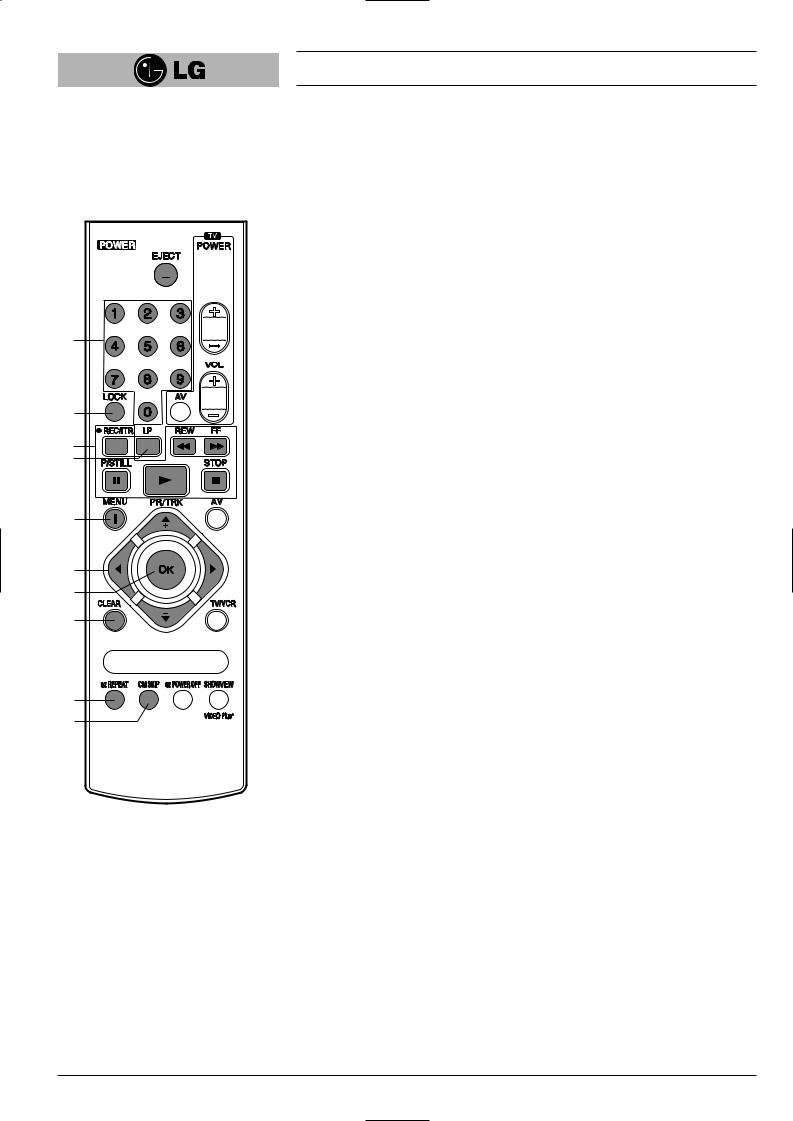
The Remote Control Handset
This video recorder is designed so that almost all of its functions can be controlled from the REMOTE CONTROL HANDSET. This must have a “line of sight” to the sensor on the front of the video recorder. It must be within an angle of 30 degrees either side of the centre. The maximum operating distance is about 7.5m (25 feet). Some functions can also be controlled with the controls on the FRONT PANEL of the video recorder.
1 |
POWER |
|
To switch the video recorder on and off. |
2 |
EJECT |
|
To eject a tape (see p 18). |
3 |
NUMBER BUTTONS: |
|
To select programme channels. To programme numeric information into On |
|
screen displays. |
4 |
LOCK |
|
To turn the LOCK function on/off (see p 33). |
5 |
Basic operation buttons; |
|
● P/STILL (see p 19, 23). |
|
● REWIND/REVIEW (see p 20). |
|
● PLAY (see p 19). |
|
● FAST FORWARD/CUE (see p 20). |
|
● STOP (see p 19). |
|
● REC/ITR (see p 23 to 24). |
6 |
TAPE SPEED SELECT (LP) |
|
To select the recording speed of the tape (see p 23). |
7 |
i (MENU) |
|
To display the on screen display (OSD) menu (see p 11). |
8 |
CURSORS (D, E, F, G)/PR(+/-)/TRK(+/-) |
|
DE: |
|
● During OSD menu, for moving the cursor, selection bar up or down. |
|
● Switches one channel programme up or down. |
|
● During playback, tracking control. |
|
● During still playback, adjusting vertical tremble. |
|
● To adjust manual fine tune for receiving normal audio and picture (see p 13). |
|
F G: |
|
● During OSD menu, for moving the cursor to the left or right. |
|
● Adjust the playback speed (see p 21). |
9 |
● To clear a data (see p 29). |
OK |
● Confirms menu selection (see p 11). ● Calls the on screen display (see p 31).
● To switch the display on the TV screen between the current time, the tape counter (in hours and minutes) and the remaining tape volume (see p 31).
This function will only operate when a tape is loaded.
10 CLEARTo reset the tape counter to zero (see p 31).
11
12 To fast forward picture search through 30 seconds of recording (see p 19).
4
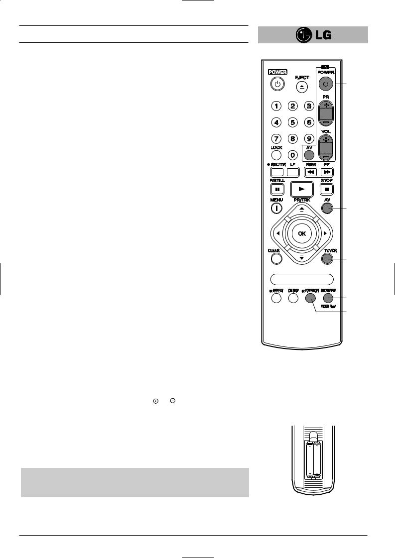
Operating the video recorder |
|
13 TV Control Buttons (see p 37) |
|
TV POWER: Turns on or off the TV. |
|
TV PR +/–: Selects TV’s channel. |
13 |
TV VOL +/–: Adjusts TV’s volume. |
|
TV AV: Selects the TV’s source. |
|
14 AVSelect input source for recording into tape (see p 23, 37).
15 TV/VCR
Set this button to;
●VCR: To monitor, view playback or view the video recorder’s tuner.
●TV: To watch TV or view another programme while recording one programme (see p 24).
16 SHOWVIEW (LV4787/LV4767/LV4747)
To display the programme menu for ShowView programming on the handset (see p 25 to 26).
17 ez POWER OFF
(see p 36).
14
15
16
17
How to install batteries
The wireless remote control is powered by two “AAA” size batteries.
1 |
Remove the battery compartment lid. |
(Lift it up while pressing the tap forward.) |
|
2 |
Load the new batteries with their polarities ( and ) aligned properly and replace |
the lid. |
AAA
AAA
●Do not use an old and a new battery together, and never use an alkaline battery with a manganese battery.
●If you do not intend to use the remote control unit for a long period of time, remove the batteries and store them in a cool, dry place.
5
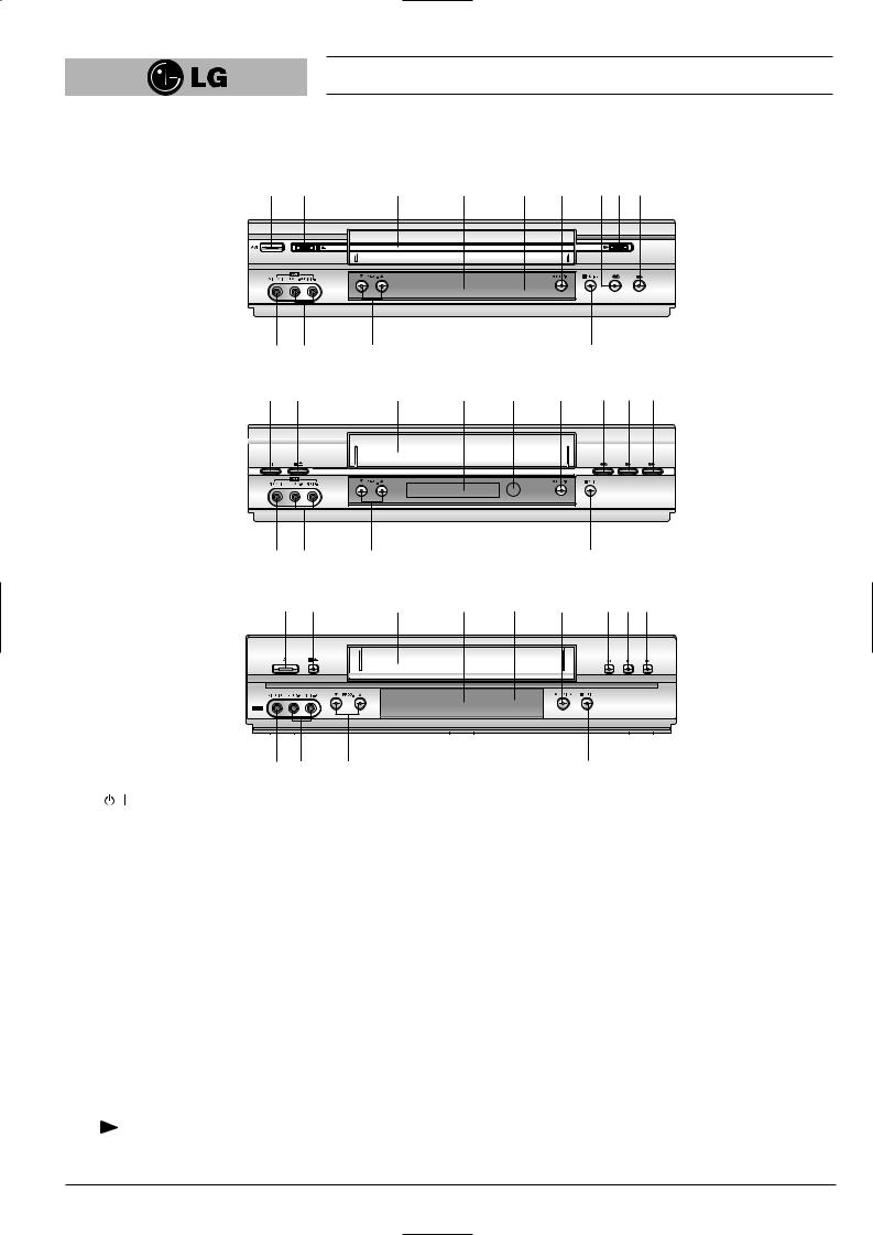
Operating the video recorder
The front of the Video Recorder
|
|
LV4787/LV4981 |
|
|
|
|
||
1 |
2 |
3 |
4 |
5 |
6 |
7 |
8 |
9 |
13 12 11 10
LV4767/LV4765
1 |
2 |
3 |
4 |
5 |
6 |
7 |
8 |
9 |
13 |
12 |
11 |
|
|
|
10 |
|
|
|
|
LV4747/LV4745 |
|
|
|
|
||
1 |
2 |
3 |
4 |
5 |
6 |
7 |
8 |
9 |
/I |
|
|
|
|
|
|
|
|
 3
3
1
2
3
4
5
6
7
8
13 12 |
12 |
To switch the video recorder on and off. (see p. 18).
 /
/
To stop the tape, or eject it from the video recorder (see p 18).
VIDEO CASSETTE COMPARTMENT
When a cassette is inserted loading is completed automatically.
MULTI FUNCTION DISPLAY
REMOTE CONTROL SENSOR
To receive the signals from the remote control handset.
REC/ITR
Used to record and set the ITR (Instant Timer Recording) time (see p 23 to 24).
REWIND
To play the tape (see p 19).
10
9 FF
10 P/STILL
Switches to still picture (see p 19), during recording to pause (see p 23).
11 PROG. (▼/▲)
Allows you to scan through memorized channels.
12 AUDIO INPUT TERMINALS (L/R)
To record audio from an external audio source (see p 8).
13 VIDEO INPUT TERMINAL
To receive a signal from another video equipment (e.g. Camcorder) (see p 9).
6
Installing your video recorder
IMPORTANT!
The guidance given on the next three pages in the most common forms of connection. However please check with your manufacturers instruction books for specific information. Make sure all connections are made with both your VCR and additional appliance unplugged from the mains to avoid damaging your equipment. Connecting a VCR using a SCART leads is one of the best ways to achieve optimum sound and picture quality from video-tape playback. If you own a stereo TV you will be able to enjoy stereo sound when playing a stereo video tape; you will be unable to enjoy this facility if you connected just a normal aerial lead.
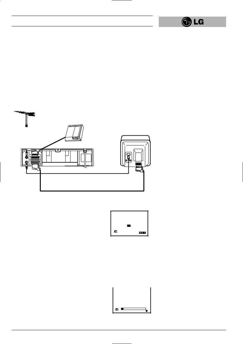
Connecting to a TV & DECODER
Aerial (NOT SUPPLIED)
The quality of the sound and picture can be greatly influenced by the positioning, quality and state of repair of your external aerial.
Decoder (NOT SUPPLIED)
Television (NOT SUPPLIED)
Rear view of your VCR
|
SORTIE |
G |
D |
|
AUDIO |
|
|
|
OUT |
L |
R |
ENTREE |
EURO AV2 |
|
DECODER |
ANTENNE |
|
||
AERIAL |
|
|
|
SORTIE |
EURO AV1 |
|
AUDIO/VIDEO |
ANTENNE |
|
|
|
RF.OUT
All connections must be made with both your VCR and Television unplugged from the mains
INITIAL PRESET
Aerial Connection Cable
(75 Ohms) (SUPPLIED)
Do not try and force the connector into
place, it should plug in easily.
SCART Lead
•If you use a SCART lead picture quality will be improved and you will be able to enjoy stereo sound when playing tapes.
For the following steps we do assume that you have just connected your video recorder for the very first time. In this case the video recorder is on after mains connection. You should not touch any buttons yet. On the connected TV you will now see.
A B CH D DK E F I
N NL P S SF ANDERE
Pr-12 |
OK i |
ACMS |
Note - If this menu does not appear, your video recorder
was programmed already.
1 |
Select the desired country with cursor “F” and “G” buttons. |
|
|
|
“A”: Austria, “B”: Belgium, “CH”: Switzerland, |
|
|
|
“D”: Deutsch, “DK”: Denmark, “E”: Spain, “F”: France, “I”: Italy, |
||
|
“N”: Norway, “NL”: Netherlands, “P”: Portugal, “S”: Sweden, |
|
|
|
“SF”: Finland. |
|
|
2 |
Press the “OK” button to start the automatic storing of |
|
|
|
|
01 C03 00 ARD |
|
|
|
|
|
|
the channels of the TV stations in your area. |
|
|
Pr-12 |
s |
E |
ACMS |
|
i |
7
Installing your video recorder
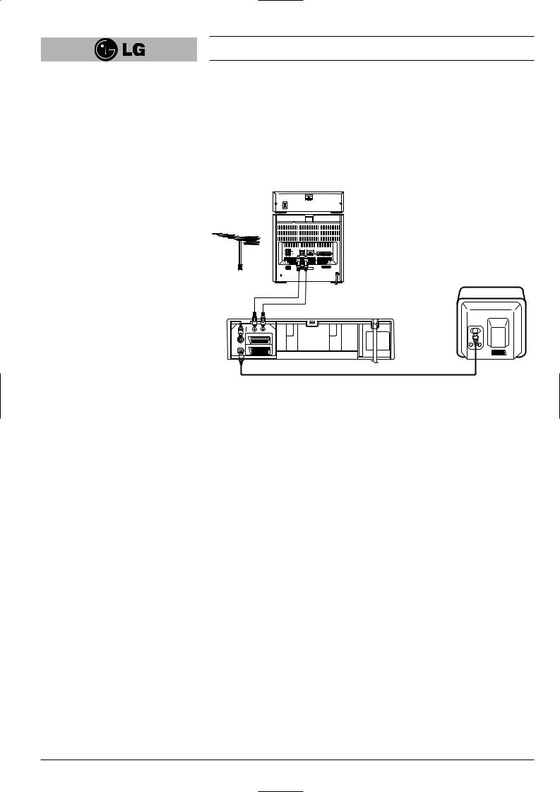
Connecting to your Hi-Fi (Audio Out)
An audio system can be connected to the AUDIO OUT sockets on the back of your
VCR.
Please remember to turn the volume to minimum on your Hi-Fi, then gradually increase the volume; this will prevent damaging your speakers and save your ears from an extremely noisy shock!
Hi-Fi (NOT SUPPLIED)
|
SORTIE |
G |
D |
|
AUDIO |
|
|
|
OUT |
L |
R |
ENTREE |
EURO AV2 |
|
DECODER |
ANTENNE |
|
||
AERIAL |
|
|
|
SORTIE |
EURO AV1 |
|
AUDIO/VIDEO |
ANTENNE |
|
|
|
RF.OUT
Audio out sockets & Phono Leads
The phono sockets for connecting your VCR to your Hi-Fi are on the back of the set; L = Left sound output, R = Right sound output. You normally have to select the AUX function on your Hi-Fi.
Please note if you press the MUTE button on your TV only the sound from the TV’s speaker is switched off, not your Hi-Fi.
8
Installing your video recorder
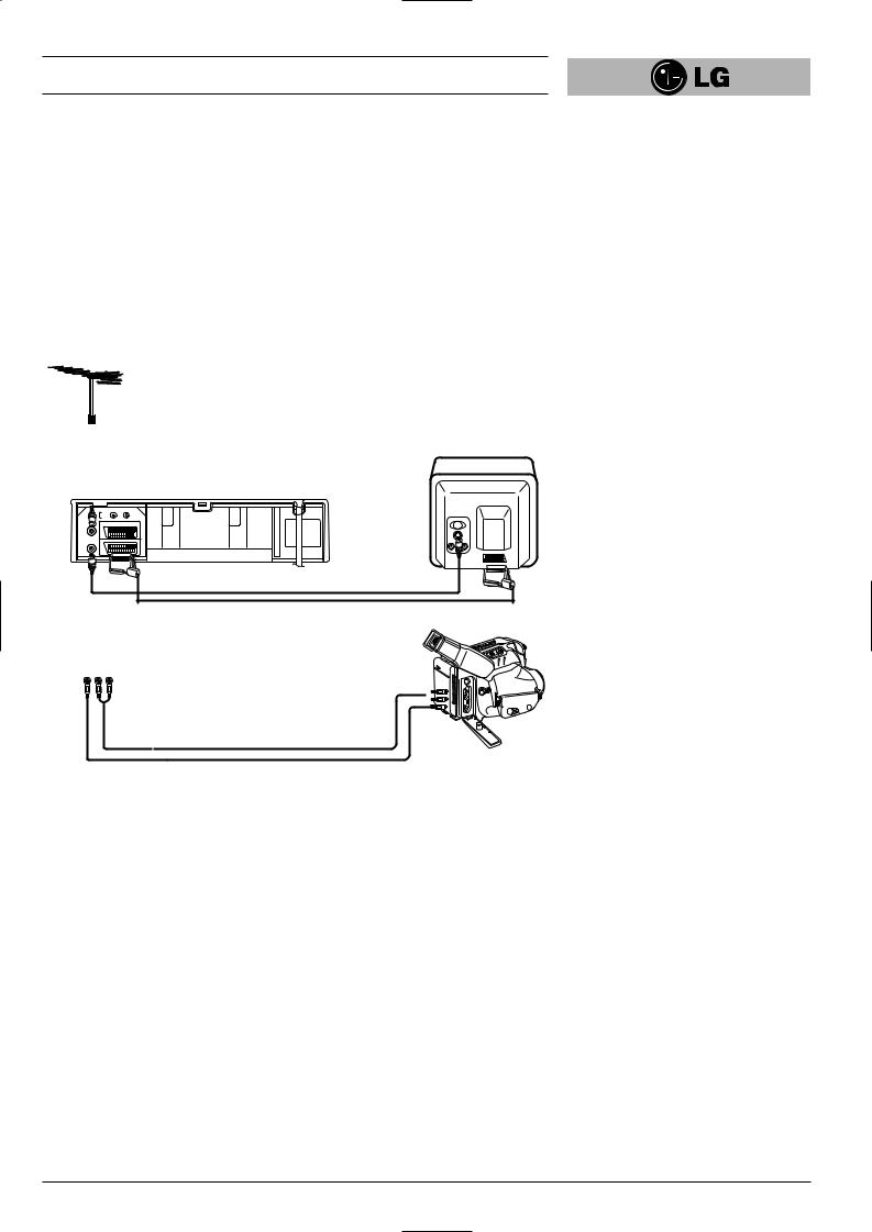
Camcorder Connection
Make sure all connections are made with both your VCR and Camcorder unplugged from the mains to avoid damaging your equipment. To make connecting your Camcorder easier we have designed the Audio IN (Left and Right) and Video IN sockets on the front panel of your VCR.
You may also use the SCART socket on the rear of your VCR as well.
Back view of your VCR
|
SORTIE |
G |
D |
|
AUDIO |
|
|
|
OUT |
L |
R |
ENTREE |
EURO AV2 |
|
DECODER |
ANTENNE |
|
||
AERIAL |
|
|
|
SORTIE |
EURO AV1 |
|
AUDIO/VIDEO |
ANTENNE |
|
|
|
RF.OUT
Front view of your VCR
VIDEO IN L(MONO)- AUDIO-AUDIOIN -R IN-R
To AUDIO OUT (L/R) 
Audio Left & Right Lead |
To VIDEO OUT |
|
Camcorder (NOT SUPPLIED)
Video Lead
Whichever socket you choose to use remember to select the appropriate recording input e.g.
SC, AV1, AV2 or AV3.
If you are using the sockets on the front panel select source AV3.
9
Setting the VCR output channel
Your TV set receives the video recorder signal like another TV station. So you have to select a programme number for the video recorder.
Take care to select this programme number, whenever you control the video recorder, or watch a recording. Only if you have selected this programme number, which we call video programme number, you will see the picture from the video recorder on the screen.
If you connect a monitor or a TV set equipped with audio and video terminals, this adjustment will not necessary. Consult the operating instructions of your TV set. Connect the video recorder as described in the section on Connections (see on previous page).
Setting the output channel of the VCR
1SETTING THE VIDEO CHANNEL WITH PLAYBACK
The output channel of the video recorder is set at UHF channel 36.
1Turn on the TV set and the video recorder.
2Play any video cassette tape on your video recorder.
3Select the correct channel (36) on your TV set.
And then you will see the picture being played in video recorder.
(Note - You will need to look at the instruction manual for your TV set if you do not know how to do this.)
2SETTING THE VIDEO CHANNEL WITH OSD (ON SCREEN DISPLAY)
1Turn on the TV set and the video recorder.
2Repeat above No. 3. And then you will see a blue background picture on the TV screen.
3Store this channel in an unused programme number on your TV set.
3 Changing the transmitter channel
If the channel 36 is already occupied at your TV set, or if the picture is distorted, you can change the transmitter channel of the video recorder.
1Select an unoccupied channel between 22 and 68 on your TV set.
2During power off mode (only clock display) press the PROG. “▼” or “▲” buttons on the VCR for more than 4 seconds.
Then, “RF36” will be displayed on the VCR’s display.
3Press the PROG. “▼” or “▲” buttons on the VCR to select another video channel e.g. between channels 22 and 68.
You can also set it to “OFF” if there is any interference when your TV is connected to the VCR with a SCART lead.
4Press the “ 
 ” button when you have finished.
10
On Screen Displays
A number of the features of this video recorder can be set and altered using the handset with On Screen Displays (menus) on the TV screen.
The Main menu
1Switch on your TV set and video recorder by pressing the “POWER” button.
2Press the “i” button to display the Main menu.
3Press the cursor “F” and “G” buttons to select the desired menu and press the “OK” button.
Note - After using the menus press the “i” button to remove menus from the TV
screen.
|
|
|
1 2 |
|
A B VCR |
|
REC |
P |
Pr-12 |
TIME |
SYS- |
C |
|
ACMS |
||||||
RSET |
DATE |
TEM |
OSD Dr. |
|||
|
f OSD |
|
+ - |
|
REC |
|
|
|
DECO- |
|
OK i |
||
AUDIO |
ON |
16:9 |
OPR |
|||
OFF |
4:3 |
DER |
|
REC
Used to record a programme with the timer (see p 27 to 28).
PR SET
Used to view stored TV stations or to set TV station information manually (see p 13 to 14).
ACMS
Used for automatic setting of the TV stations (see p 12).
TIME DATE
To set the clock manually (see p 17).
SYSTEM (AUTO → PAL → MESECAM)
Select the colour system used for playback and recording (see p 22).
ABC OSD
Allows you to select the language of the On Screen Display. You can select between
ENGLISH, DEUTSCH, ITALIANO, ESPAÑOL, E^^HNIKA and PORTUGUÊS.
Dr.
To check a problem with your VCR (see p 33).
AUDIO (STEREO, LEFT, RIGHT or MONO)
Used to select the channel for audio output (see p 34).
OSD (On Screen Display)
Switches the on screen display OFF or ON (see p 31).
16:9/4:3
To select the aspect ratio of your TV (see p 33).
● AUTO: for playing back wide-screen programmes as wide, normal programmes as normal.
●4:3 : for recording and playback with a normal format.
●16:9 : for recording and playback with a 16:9 Wide-screen format recording.
DECODER
To use DECODER scart socket for the connection of a pay-TV decoder (see p 22).
OPR
To improve the playback picture (see p 20).
11

Storing TV stations
Up to 88 TV stations (88 channels) can be stored in the memory of this video recorder. These can be set automatically or manually.
Automatic tuning
To carry out Automatic tuning:
1 |
Turn on the TV and the video recorder |
|
(with the “POWER” button). |
2 |
Press the “i” button and select “ACMS ” by using the |
|
cursor “F” and “G” buttons. |
|
|
|
1 2 |
|
A B VCR |
|
REC |
P |
Pr-12 |
TIME |
SYS- |
C |
|
|
|
|||||
RSET |
ACMS |
DATE |
TEM |
OSD Dr. |
Pr-12 |
|
|
fOSD |
|
+ - |
|
|
ACMS |
AUDIO |
ON |
16:9 |
DECO- |
OPR |
|
OK i |
OFF |
4:3 |
DER |
|
3 |
Press the “OK” button. |
4 |
Select the desired country with cursor |
“F” and “G” buttons.
“A”: Austria, “B”: Belgium, “CH”: Switzerland,
“D”: Deutsch, “DK”: Denmark,
“E”: Spain, “F”: France, “I”: Italy,
“N”: Norway, “NL”: Netherlands,
“P”: Portugal, “S”: Sweden, “SF”: Finland, Others.
5 Press the “OK” button to start the automatic storing of the channels of the TV stations in your area.
The VCR’s clock will be set automatically when automatic tuning has finished (LV4787/LV4767/ LV4747).
If the clock is wrong please see “Setting the video recorder’s clock manually” on page 17.
A |
B |
CH |
D |
DK |
E F I |
N |
NL |
P |
S |
SF |
OTHERS |
Pr-12 |
OK i |
ACMS |
01 C03 |
00 |
ARD |
s |
E |
Pr-12 |
i |
ACMS |
6 |
After finishing the storing, the video |
|
recorder will sort the stations. |
|
Automatic channel tuning has been |
|
completed when the “TV station table” |
|
menu appears on the TV screen. |
7 |
Press the “i” button to remove the |
|
menus from the TV screen. |
|
|
|
|
|
|
|
|
|
|
01 |
C03 |
00 |
ARD |
|
|
||
02 |
C02 |
00 |
ZDF |
|||||
03 |
S40 |
00 |
WDR3 |
|||||
04 |
S11 |
00 |
BR3 |
|||||
05 |
C02 |
00 |
HR3 |
|||||
06 |
- - |
- - |
- - - - - |
|
|
|||
07 |
- - |
- - |
- - - - - |
|
|
|||
08 |
- - |
- - |
- - - - - |
|
|
|||
P |
|
MOVE: |
|
|
|
|
|
|
|
DELETE: |
|
, |
OK i |
|
|||
RSET |
|
|
|
|||||
|
|
|
|
|
|
|
|
|
12
 Loading...