


SINGLE-ZONE VERTICAL AIR HANDLING UNIT ENGINEERING MANUAL
Single-Zone Vertical Air Handling Unit System
18,000 - 48,000 Btu/h
LV180HV4 (18,000 Btu/h)
LV240HV4 (24,000 Btu/h) LV360HV4 (36,000 Btu/h)
LV420HV (42,000 Btu/h)
LV480HV (48,000 Btu/h)
PROPRIETARY DATA NOTICE
This document, as well as all reports, illustrations, data, information, and other materials are the property of LG Electronics U.S.A., Inc., and are disclosed by LG Electronics U.S.A., Inc. only in confidence.
This document is for design purposes only.
A summary list of safety precautions is on page 3.
For more technical materials such as submittals, catalogs, installation, owner’s, and service manuals, visit www.lghvac.com.
For continual product development, LG Electronics U.S.A., Inc., reserves the right to change specifications without notice. © LG Electronics U.S.A., Inc.
TABLE OF CONTENTS
Unit Nomenclature.......................................................................................................................................................................................................... |
4 |
LG Air Conditioner Technical Solution (LATS).......................................................................................................................................................... |
5-6 |
Vertical Air Handling Unit Product Data................................................................................................................................................................... |
7-50 |
Mechanical Specifications |
8-9 |
General Data |
10-12 |
Electrical Data |
13 |
Functions, Controls, and Options |
14-15 |
Dimensions |
16-19 |
Acoustic Data |
20-30 |
Refrigerant Flow Diagrams |
31-32 |
Wiring Diagrams, Dip Switch Settings |
33-37 |
Electrical Connections |
38-42 |
External Static Pressure andAir Flow Ranges |
43-47 |
Accessories |
48-50 |
Vertical Air Handling Unit Performance Data-------------------------------------------------------------------------------------------------------------------------------- |
51-69 |
Cooling Capacity Data |
52-56 |
Heating Capacity Data |
57-61 |
Maximum Heating Capacity Data |
62-66 |
Equipment Selection Procedure |
67-69 |
Vertical Air Handling Unit Application Guidelines................................................................................................................................................ |
70-81 |
Placement Considerations |
71-74 |
Clearances |
75-77 |
Installing Outdoor Unit Indoors |
78-79 |
Refrigerant Piping Design |
80-81 |
TABLE OF SYMBOLS
DANGER |
This symbol indicates an imminently hazardous situation which, if not avoided, will result in death or |
serious injury. |
|
|
|
WARNING |
This symbol indicates a potentially hazardous situation which, if not avoided, could result in death or |
serious injury. |
|
|
|
CAUTION |
This symbol indicates a potentially hazardous situation which, if not avoided, may result in minor or |
moderate injury. |
|
|
|
Note: |
This symbol indicates situations that may result in equipment or property damage accidents only. |
|
|
|
This symbol indicates an action that must not be performed. |
|
|
Introduction
Due to our policy of continuous product innovation, some specifications may change without notification. |
|
©LG Electronics U.S.A., Inc., Englewood Cliffs, NJ.All rights reserved. “LG” is a registered trademark of LG Corp. |
INTRODUCTION | 3 |
UNIT NOMENCLATURE
Single Zone Vertical Air Handling Unit Engineering Manual
Indoor Units and Outdoor Units
L |
|
V |
|
N |
|
180 |
|
H |
|
V |
|
4 |
|
|
|
|
|
|
|
|
|
|
|
|
|
L = LG
Frame Type:
A: Art Cool™
S: Standard
C:Four-Way Ceiling-Cassette
D:Ceiling-Concealed Duct (Low Static)
H:Ceiling-Concealed Duct (High Static)
V:Vertical-Horizontal Air Handling
N: Indoor Unit
U: Outdoor Unit
No N or U: System
Nominal Capacity
(Nominal cooling capacity in Btu/h): 18 = 18,000 48 = 48,000 24 = 24,000 36 = 36,000 42 = 42,000
System Type:
H = Heat Pump
Style:
SV = High Efficiency Inverter
VP = Gallery
YV = Premier
EV = Mega
V = Standard Inverter
T = Thermostat Compatible
Generation:
|
Due to our policy of continuous product innovation, some specifications may change without notification. |
4 | INTRODUCTION |
©LG Electronics U.S.A., Inc., Englewood Cliffs, NJ.All rights reserved. “LG” is a registered trademark of LG Corp. |
LG AIR CONDITIONER
TECHNICAL SOLUTION (LATS)
LG Air Conditioner Technical Solution (LATS) Software
A properly designed and installed refrigerant piping system is critical to the optimal performance of LG air-conditioning systems. To assist engineers, LG offers, free of charge, LG Air Conditioner Technical Solution (LATS) software—a total design solution for LG air conditioning systems. Contact your LG Rep for the best software program for your application.
To reduce the risk of designing an improper applied system or one that will not operate correctly, LG requires that LATS software be used on all projects.
Formats
LATS is available to LG customers in three user interfaces: LATS HVAC, LATS CAD2, and LATS Revit. All three LATS formats are available through www.myLGHVAC.com, or contact an LG Sales Representative.
LATS HVAC is a Windows®-based application that aids engineers in designing LG Variable Refrigerant Flow (VRF), Multi F / Multi F MAX, Single-Zone, and Energy Recovery Ventilator (ERV) systems.
*Windows® is a registered mark of Microsoft® Corporation.
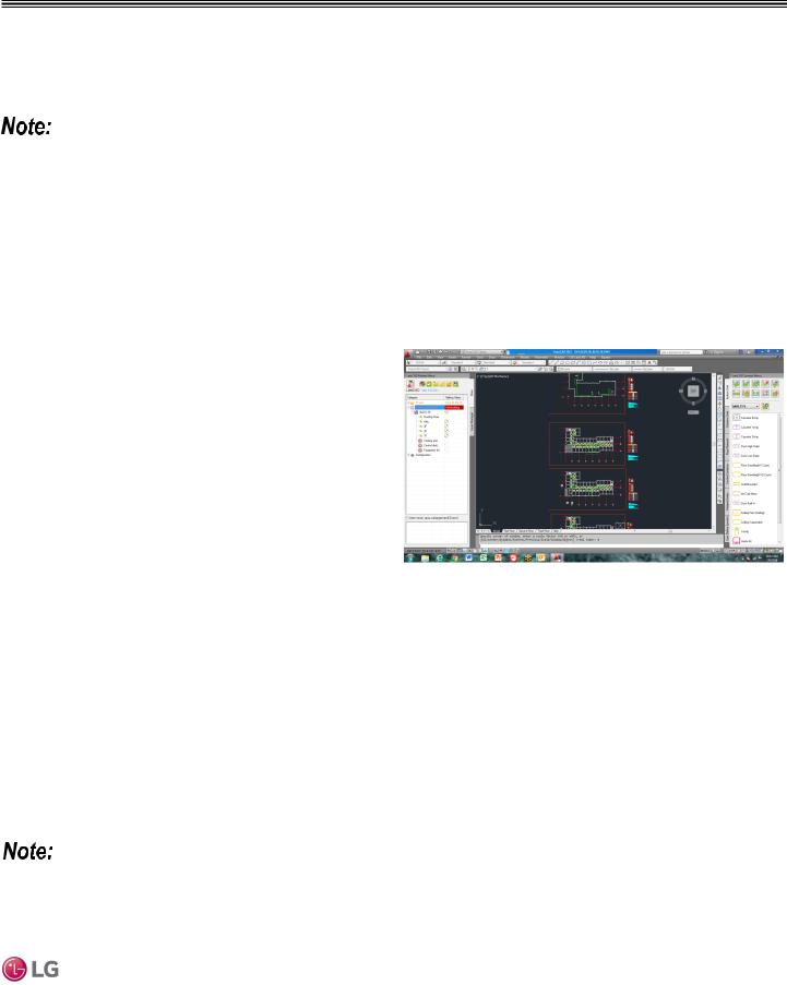
LATS CAD2 combines the LG LATS program with AutoCAD®
software**. It permits engineers to layout and validate LG Multi V Figure 1:Example of LATS CAD2. Variable Refrigerant Flow (VRF), Multi F / Multi F MAX, Single-Zone,
and Energy Recovery Ventilator (ERV) systems directly into CAD drawings.
LATS Revit integrates the LG LATS program with Revit® software**. It permits engineers to layout and validate Multi V VRF systems directly into Revit drawings.
**AutoCAD® and Revit® are both registered marks ofAutodesk, Inc.
Features
All LG product design criteria have been loaded into the program, making LATS simple to use: double click or drag and drop the component choices. Build systems in Tree Mode where the refrigerant system can be viewed. Switch to a Schematic diagram to see the electrical and communications wiring.
LATS software permits the user to input region data, indoor and outdoor design temperatures, modify humidity default values, zoning, specify type and size of outdoor units and indoor units, and input air flow and external static pressure (ESP) for ducted indoor units.
The program can also:
•Import building loads from a separate Excel file.
•Present options for outdoor unit auto selection.
•Automatically calculate component capacity based on design conditions for the chosen region.
•Verify if the height differences between the various system components are within system limits.
•Provide the correct size of each refrigerant piping segment and LG Y-Branches and Headers.
•Adjust overall piping system length when elbows are added.
•Check for component piping limitations and flag if any parameters are broken.
•Factor operation and capacity for defrost operation.
•Calculate refrigerant charge, noting any additional trim charge.
•Suggest accessories for indoor units and outdoor units.
•Run system simulation.
Features depend on which LATS program is being used, and the type of system being designed.
Introduction
Due to our policy of continuous product innovation, some specifications may change without notification. |
|
©LG Electronics U.S.A., Inc., Englewood Cliffs, NJ.All rights reserved. “LG” is a registered trademark of LG Corp. |
INTRODUCTION | 5 |
Single Zone Vertical Air Handling Unit Engineering Manual
LG AIR CONDITIONER
TECHNICAL SOLUTION (LATS)
LATS Generates a Complete Project Report
LATS software also generates a report containing project design parameters, cooling and heating design data, system component performance, and capacity data. The report includes system combination ratio and refrigerant charge calculations; and provides detailed bill of material, including outdoor units, indoor units, control devices, accessories, refrigerant pipe sizes segregated by building, by system, by pipe size, and by pipe segments. LATS can generate an Excel GERP report that can imported into the LG SOPS pricing and ordering system.
Proper Design to Install Procedure
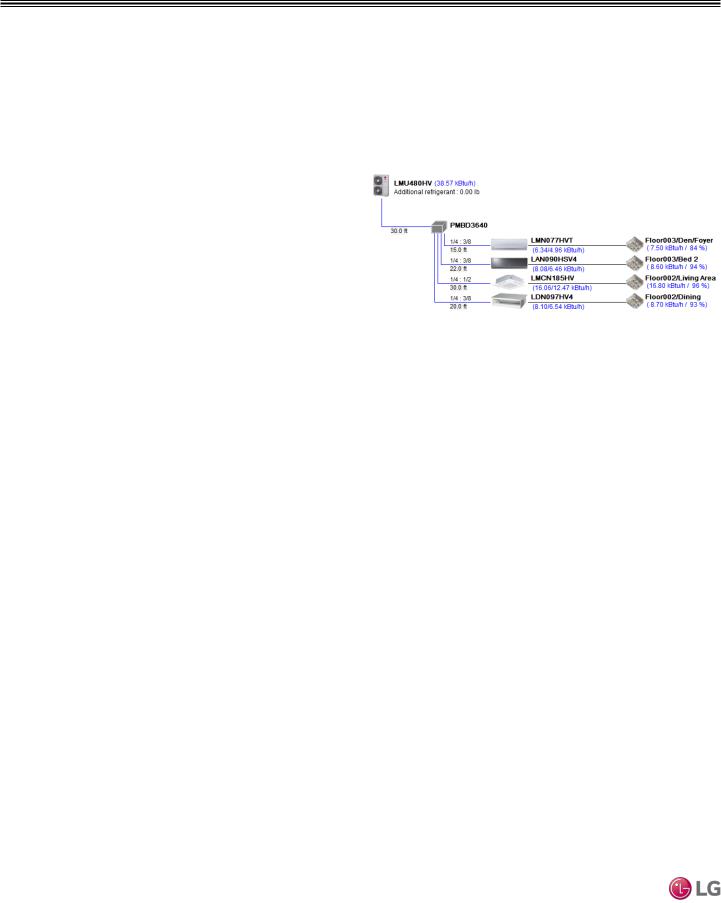
LG encourages a two report design-to-install-procedure. After the |
Figure 2:Example of a LATS Tree Diagram. |
design engineer determines building / zone loads and other details, |
|
the engineer opens the LATS program and inputs the project’s infor- |
|
mation. When the design is complete, the “Auto Piping” and “System |
|
Check” functions must be used to verify piping sizes, limitations, and |
|
if any design errors are present. If errors are found, engineers must |
|
adjust the design, and run Auto Piping and System Check again. |
|
When the design passes the checks, then the engineer prints out |
|
a project “Shop Drawing” (LATS Tree Diagram) and provides it to |
|
the installing contractor. The contractor must follow the LATS Tree |
|
Diagram when building the piping system, but oftentimes the design |
|
changes on the building site: |
|
•Architect has changed location and/or purpose of room(s).
•Outdoor unit cannot be placed where originally intended.
•Structural elements prevent routing the piping as planned.
•Air conditioning system conflicts with other building systems (plumbing, gas lines, etc.).
The contractor must mark any deviation from the design on the Shop Drawing, including as-built straight lines and elbows. This “Mark Up” drawing must be returned to the design engineer or Rep, who must input contractor changes into the LATS file. (Copy the original LATS software file, save and rename as a separate file, and modify all piping lengths by double-clicking on each length and editing information.) Like the shop drawing, the Auto Piping and System Check must also be run on this new “As Built” drawing. The design engineer or Rep must then provide the final As Built file to the contractor. The Mark Up version must be compared to the As Built version for the following:
•Differences in pipe diameter(s). If incorrect diameters have been installed, the piping must be changed out. If pipe diameters have changed, check to see if Y-Branches will also need to be changed.
•Changes to outdoor unit and indoor unit capacities. Capacities changes may impact line length changes.
•Additional refrigerant charge quantity (“Trim Charge”). Trim charge will change if piping lengths and diameters change. The As Built version must reflect installed piping lengths to ensure correct trim charge.
All documents submitted by the contractor, as well as the Shop Drawing and the As Built Drawing files must be provided for commissioning purposes. Model and serial numbers for all system components must also be submitted. If the steps previously detailed are not followed, and all documents are not provided to the LG Commissioner, the project runs the risk of not being commissioned and voiding any limited warranty LG offers on the equipment.
|
Due to our policy of continuous product innovation, some specifications may change without notification. |
6 | INTRODUCTION |
©LG Electronics U.S.A., Inc., Englewood Cliffs, NJ.All rights reserved. “LG” is a registered trademark of LG Corp. |
VERTICAL AIR HANDLING UNIT PRODUCT DATA
“Mechanical Specifications” on page 8 “General Data” on page 10
“Electrical Data” on page 13
“Functions, Controls, and Options”on page 14 “Dimensions” on page 16
“Acoustic Data” on page 20 “Refrigerant Flow Diagrams” on page 31 “Wiring Diagrams” on page 33 “Electrical Connections” on page 38
“External Static Pressure and Airflow Ranges” on page 43 “Accessories” on page 48
MECHANICAL SPECIFICATIONS
Single Zone Vertical Air Handling Unit Engineering Manual
Casing
The unit is designed to operate in vertical up flow, down flow (requires conversion kit sold separately), horizontal left, and horizontal right configurations.
Supply air exits from the top and return air enters from the bottom for a vertical up flow configuration. Return air opening is from the top for the vertical down flow configuration. Return air opening is from right end or left end when in horizontal configuration.
The airflow circulation of the supply air and return air is reversed in a vertical down flow configuration. Return air plenum sub-base is to be field provided. Supply air opening has a male flange for duct connection.
The unit case is made of 22-gauge coated metal and the external surfaces are finished with a high gloss baked enamel finish. Finish color is “morning fog” (medium beige). Cold surfaces are galvanized steel.
The cold surfaces of the case are internally insulated with ½ inch foil faced, polystyrene fiber insulation. The inside surface of the fan assembly door access panel is treated with ½ inch polystyrene fiber insulation, encapsulated on both sides, and sealed along the edges with a reinforced foil-faced covering to prevent deterioration caused by panel removal.
All access panels are provided with gasket seals to minimize air leakage. The unit case is designed to accept an internal, optional, LG electric strip heater. The unit bears the ETL label. Unit breaker, fuses, and / or disconnect are provided by others.
Fan Assembly and Control
The indoor unit has an integral fan assembly consisting of a galvanized steel housing and a forward-curved fan wheel. The direct drive fan/motor assembly is mounted on rubber grommets isolating the rotating assembly from the fan housing. The fan motor is a Brushless Digitally-Controlled design (BLDC), having permanently lubricated and sealed ball bearings. The fan motor includes thermal, overcurrent and low RPM protection. The fan/motor assembly is mounted on vibration attenuating rubber grommets. The fan impeller is statically and dynamically balanced. Fan speed is controlled using a microprocessor-based direct digital control algorithm that provides a minimum of a high fan speed in cooling thermal ON and low fan speed in cooling thermal OFF, high fan speed in heating thermal ON and fan off in heating thermal OFF. The fan speeds can be field adjusted between low, medium, and high speeds and DIP switch settings will allow the fan to run constantly during defrost or oil return modes. Each setting can be field adjusted from the factory setting (RPM/ESP). The setting provides delivery of the high speed air volume against an external static pressure of up to 0.70″ in-wg (NJ frame - 18k and 24k), and 1.00″ in-wg (NK frame - 36k, 42k, and
48k).
Air Filter
The unit comes with a filter rack sized to hold a field-
provided 16” x 20” x 1” (NJ frame) or
24” x 20” x 1” (NK frame) filter cartridge.
The filter rack is equipped with guides that keep the filter centered in the rack. Filter service access is from the front of the unit without removing the coil or fan area access panels. Filter access door is provided with thumb screws that can be removed.
Optional Auxiliary Electric Heat
Module(s)
Figure 3: Vertical Air
Handling Indoor Unit.
LG optional electric heat modules are designed for field installation in the reheat position. The electric heat module is
provided with heating elements, contactors, relays, high temperature safety switch, and interconnecting control wiring harness with a quick connect plug for easy connection to the air handling unit control board. Auxiliary heat modules are available in nominal capacities of 3, 5, 8, 10, 15, and 20 kW. Heating elements are powered from a field provided separate power source. 3kW through 10 kW modules are powered from a single power wire. The 15kW and 20 kW modules are powered from two power wires.
Heating module breakers, fuses, and / or disconnects are to be field provided.
The optional electric heater when used with the provided simple controller or a 3rd party thermostat (via dry contact connection), will have automatic heating operation based on the internal logic. If
manual heater operation is intended, an LG Programmable controller is required.
Microprocessor Control
The indoor unit is provided with an integrated control panel with built-in dry contact to communicate with the outdoor unit. All unit operation parameters are stored in non-volatile memory resident on the unit microprocessor. The microprocessor controls space temperature through using the value provided by temperature sensors within the indoor unit. A field-supplied communication cable must be installed to connect the indoor unit(s) to the outdoor unit.
8 | PRODUCT DATA |
Due to our policy of continuous product innovation, some specifications may change without notification. |
|
©LG Electronics U.S.A., Inc., Englewood Cliffs, NJ.All rights reserved. “LG” is a registered trademark of LG Corp. |

MECHANICAL SPECIFICATIONS
Controls
The indoor unit is supplied with an LG wired controller. Communication cable from the outdoor unit to the indoor unit must be a minimum of 18 AWG, four (4) conductor, shielded or unshielded (if shielded, must be grounded to chassis at ODU only) and must comply with applicable local and national codes.
Condensate
The unit is designed for gravity draining of condensate.
Condensate Drain Pan
The condensate drain pan is constructed of HIPS (high impact polystyrene resin).
Coil
The indoor unit coil is constructed with grooved design copper tubes with slit coil fins, 3 rows, 18 fins per inch.
Controls Features
•Inverter (Variable speed fan)
•Child lock function
•Auto changeover
•Auto restart operation
•Dehumidifying function
•Two thermistor control
•Group control
•External static pressure control
•Self-diagnostics function
•Wired thermostat included
Vertical Down Flow Configuration
NJ and NK frames come factory configured for vertical up flow.
Down flow configuration requires a conversion kit sold separately
(model numbers: PNDFJ0 for NJ frame and PNDFK0 for NK frame).
The kit contains support brackets for the evaporator coil/drain pan subassembly, addition screws, and a replace front panel to accommodate the coil and drain connections for down flow configuration.
Data Product
Due to our policy of continuous product innovation, some specifications may change without notification. |
PRODUCT DATA | 9 |
©LG Electronics U.S.A., Inc., Englewood Cliffs, NJ.All rights reserved. “LG” is a registered trademark of LG Corp. |
|
GENERAL DATA
Pairing Table
Single Zone Vertical Air Handling Unit Engineering Manual
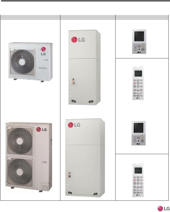
Table 1: Single Zone Vertical Air Handling Unit Pairing Table
Outdoor Unit Model |
Indoor Unit Model |
Remote Controller |
LUU188HV |
LVN180HV4, LVN240HV4 (NJ frame) |
PQRCVCL0QW (LG supplied, wired) |
LUU248HV |
|
|
PQWRHQ0FDB (Optional, wireless)
LUU368HV |
LVN360HV4, LVN420HV, LVN480HV |
PQRCVCL0QW (LG supplied, wired) |
LUU428HV |
(NK frame) |
|
LUU488HV |
|
|
PQWRHQ0FDB (Optional, wireless)
10 | PRODUCT DATA |
Due to our policy of continuous product innovation, some specifications may change without notification. |
|
©LG Electronics U.S.A., Inc., Englewood Cliffs, NJ.All rights reserved. “LG” is a registered trademark of LG Corp. |
GENERAL DATA / SPECIFICATIONS
Table 2: Vertical Air Handling Unit General Data.
Type |
|
|
Vertical Air Handling Unit |
|
||
System (Model) (Indoor Unit / Outdoor |
LV180HV4 |
LV240HV4 |
|
LV360HV4 |
LV420HV |
LV480HV |
Unit) |
(LVN180HV4/ |
(LVN240HV4/ |
|
(LVN360HV4/ |
(LVN420HV/ |
(LVN480HV/ |
|
LUU188HV) |
LUU248HV) |
|
LUU368HV) |
LUU428HV) |
LUU488HV) |
Cooling Capacity (Min/Rated/Max) |
8,000 ~ 18,000 ~ |
9,000 ~ 24,000 ~ |
|
14,000 ~ 36,000 ~ |
17,000 ~ 42,000 ~ |
18,000 ~ 48,000 ~ |
(Btu/h) |
24,000 |
28,000 |
|
44,000 |
48,000 |
53,000 |
Cooling Power Input1 (kW) |
0.65 ~ 1.35 ~ 2.70 |
0.70 ~ 1.92 ~ 3.20 |
|
1.25 ~ 2.88 ~ 4.80 |
1.35 ~ 3.80 ~ 5.30 |
1.40 ~ 4.80 ~ 6.00 |
EER |
13.33 |
12.50 |
|
12.50 |
11.05 |
10.00 |
SEER |
19.0 |
18.0 |
|
18.0 |
17.0 |
16.5 |
Heating Capacity (Min/Rated/Max) |
9,000 ~ 20,000 ~ |
10,000 ~ 27,000 ~ |
|
15,000 ~ 40,000 ~ |
18,000 ~ 47,000 ~ |
19,000 ~ 56,000 ~ |
(Btu/h) |
23,000 |
30,000 |
|
47,000 |
55,000 |
60,000 |
Heating Power Input1 (kW) |
0.65 ~ 1.60 ~ 2.10 |
0.75 ~ 2.26 ~ 2.80 |
|
1.35 ~ 3.39 ~ 5.05 |
1.45 ~ 4.00 ~ 5.65 |
1.50 ~ 5.10 ~ 6.20 |
COP |
3.66 |
3.50 |
|
3.46 |
3.44 |
3.22 |
HSPF |
9.5 |
10.0 |
|
10.0 |
10.0 |
9.5 |
Maximum Heating Capacity (Btu/h) |
|
|
|
|
|
|
Outdoor 17°F) (WB)/Indoor 70°F (DB) |
18,000 |
22,000 |
|
32,000 |
37,000 |
40,000 |
|
|
|
|
|
|
|
Outdoor 5°F(WB)/Indoor 70°F (DB) |
16,000 |
20,000 |
|
30,000 |
32,000 |
34,000 |
|
|
|
|
|
|
|
Power Input [W] @ Outdoor 5°F (WB) |
2,500 |
3,200 |
|
4,400 |
4,800 |
5,250 |
Outdoor -4 °F(WB)/Indoor 70°F (DB) |
11,000 |
15,000 |
|
22,000 |
24,000 |
26,000 |
Power Supply V, Ø, Hz |
|
|
|
208-230 / 1 / 60 |
|
|
Outdoor Unit Operating Range |
|
|
|
|
|
|
Cooling (°F DB) |
|
|
|
5 - 118 |
|
|
Optional Wind Baffle Cooling (°F DB) |
|
|
|
Yes (-4) |
|
|
Heating (°F WB) |
-4 - 64 |
-4 - 64 |
|
-4 - 64 |
-4 - 64 |
-4 - 64 |
Indoor Unit Operating Range |
|
|
|
|
|
|
Cooling (°F WB) |
|
|
|
57 - 77 |
|
|
Heating (°F DB) |
|
|
59 - 81 |
|
|
|
Indoor Temperature Setting Range |
|
|
|
|
|
|
Cooling (°F DB) |
|
|
|
65 - 86 |
|
|
Heating (°F WB) |
|
|
61 - 86 |
|
|
|
EEV: Electronic Expansion Valve, IDU: Indoor Unit, ODU: Outdoor Unit. This unit comes with a dry helium charge.
This data is rated 0 ft above sea level, with 24.6 ft of refrigerant line per indoor unit and a 0 ft level difference between outdoor and indoor units.
Cooling capacity rating obtained with air entering the indoor coil at 80ºF dry bulb (DB) and 67ºF wet bulb (WB); and outdoor ambient conditions of 95ºF dry bulb (DB) and 75ºF wet bulb (WB).
Heating capacity rating obtained with air entering the indoor unit at 70ºF dry bulb (DB) and 60ºF wet bulb (WB); and outdoor ambient conditions of 47ºF dry bulb (DB) and 43ºF wet bulb (WB).
1 Power Input is rated at high speed.
2 All communication / connection (power) cable from the outdoor unit to the indoor unit are field supplied and is to be a minimum four-conductor, 18 AWG, stranded, shielded or unshielded (if shielded, it must be grounded to the chassis of ODU only), and must comply with applicable local and national codes.
3 Take appropriate actions at the end of HVAC equipment life to recover, recycle, reclaim or destroy R410A refrigerant according to applicable regulations (40 CFR Part 82, Subpart F) under section 608 of CAA.
4 Sound pressure levels are tested in an anechoic chamber under ISO Standard 3745 and are the same in both cooling and heating mode. These values can increase due to ambient conditions during operation.
5 Piping lengths are equivalent.
Data Product
Due to our policy of continuous product innovation, some specifications may change without notification. |
PRODUCT DATA | 11 |
©LG Electronics U.S.A., Inc., Englewood Cliffs, NJ.All rights reserved. “LG” is a registered trademark of LG Corp. |
|

GENERAL DATA / SPECIFICATIONS
Single Zone Vertical Air Handling Unit Engineering Manual
Table 3: Vertical Air Handling Unit General Data, continued.
Type |
|
|
Vertical Air Handling Unit |
|
|
System (Model) (Indoor Unit / Outdoor |
LV180HV4 |
LV240HV4 |
LV360HV4 |
LV420HV |
LV480HV |
Unit) |
(LVN180HV4/ |
(LVN240HV4/ |
(LVN360HV4/ |
(LVN420HV/ |
(LVN480HV/ |
|
LUU188HV) |
LUU248HV) |
LUU368HV) |
LUU428HV) |
LUU488HV) |
Unit Data |
|
|
|
|
|
Refrigerant Type3 |
|
|
R410A |
|
|
Additional Refrigerant Charge (oz./ft.) |
|
|
0.43 |
|
|
Refrigerant Control |
|
|
EEV |
|
|
Indoor Unit Sound Pressure Level (dB(A)) |
42 / 42 / 41 |
43 / 42 / 41 |
45 / 44 / 43 |
48 / 45 / 44 |
49 / 48 / 44 |
(H/M/L)4 |
|
|
|
|
|
Outdoor Unit Sound Pressure Level |
48 / 52 |
48 / 52 |
52 / 54 |
52 / 54 |
52 / 54 |
(dB(A)) (Cool/Heat)4 |
|
|
|
|
|
Indoor Unit Net / Shipping Weight (lbs.) |
129 / 140 |
129 / 140 |
165 / 188 |
165 / 188 |
165 / 188 |
Outdoor Unit Net / Shipping Weight (lbs.) |
129 / 141 |
129 / 141 |
203 / 232 |
203 / 232 |
203 / 232 |
|
|
|
|
|
|
Power Wiring / Communications Cable |
|
|
4 x 18 |
|
|
(No. x AWG)2 |
|
|
|
|
|
Power Supply (No. xAWG) |
3 x 12 |
3 x 12 |
3 x 10 |
3 x 10 |
3 x 10 |
Compressor (Type x Qty.) |
|
|
Twin Rotary x |
1 |
|
Dehumidification Rate (pts./hr.) |
2 |
2.5 |
3.4 |
4.3 |
5.2 |
Fan |
|
|
|
|
|
Indoor Unit Type x Qty. |
|
|
Sirocco x 1 |
|
|
Outdoor Unit Type x Qty. |
Propeller x 1 |
Propeller x 1 |
Propeller x 2 |
Propeller x 2 |
Propeller x 2 |
Motor / Drive |
|
|
Brushless Digitally Controller / Direct |
|
|
Airflow Rate |
|
|
|
|
|
Indoor Unit (H / M / L [CFM]) |
640 / 580 / 480 |
710 / 640 / 480 |
1,100 / 1,000 / 900 |
1,260 / 1,100 / 1,000 |
1,400 / 1,260 / |
|
|
|
|
|
1,000 |
Outdoor Unit (CFM) |
2,048 |
2,048 |
1,942 x 2 |
1,942 x 2 |
1,942 x 2 |
Factory Set (High) External Static Pressure |
|
|
0.3 |
|
|
(in.wg) |
|
|
|
|
|
|
|
|
|
|
|
Piping |
|
|
|
|
|
Liquid (in.) |
|
|
3/8 |
|
|
Vapor (in.) |
|
|
5/8 |
|
|
Indoor Unit Condensate Drain I.D. (in.) |
|
|
Primary & Secondary: 3/4 FPT |
|
|
|
|
|
|
|
|
Minimum / Maximum Pipe Length (ft.)5 |
6.6 / 164 |
6.6 / 164 |
6.6 / 246 |
6.6 / 246 |
6.6 / 246 |
Piping Length (no additional refrigerant, ft.) |
|
|
24.6 |
|
|
Maximum Elevation Difference (ft.) |
|
|
98.4 |
|
|
EEV: Electronic Expansion Valve, IDU: Indoor Unit, ODU: Outdoor Unit. This unit comes with a dry helium charge.
This data is rated 0 ft above sea level, with 24.6 ft of refrigerant line per indoor unit and a 0 ft level difference between outdoor and indoor units.
Cooling capacity rating obtained with air entering the indoor coil at 80ºF dry bulb (DB) and 67ºF wet bulb (WB); and outdoor ambient conditions of 95ºF dry bulb (DB) and 75ºF wet bulb (WB). Heating capacity rating obtained with air entering the indoor unit at 70ºF dry bulb (DB) and 60ºF wet bulb (WB); and outdoor ambient conditions of 47ºF dry bulb (DB) and 43ºF wet bulb (WB).
1Power Input is rated at high speed.
2All communication / connection (power) cable from the outdoor unit to the indoor unit
are field supplied and is to be a minimum four-conductor, 18 AWG, stranded, shielded or unshielded (if shielded, it must be grounded to the chassis of ODU only), and must comply with applicable local and national codes.
3 Take appropriate actions at the end of HVAC equipment life to recover, recycle, reclaim or destroy R410A refrigerant according to applicable regulations (40 CFR Part 82, Subpart F) under section 608 of CAA.
4 Sound pressure levels are tested in an anechoic chamber under ISO Standard 3745 and are the same in both cooling and heating mode. These values can increase due to ambient conditions during operation.
5 Piping lengths are equivalent.
12 | PRODUCT DATA |
Due to our policy of continuous product innovation, some specifications may change without notification. |
|
©LG Electronics U.S.A., Inc., Englewood Cliffs, NJ.All rights reserved. “LG” is a registered trademark of LG Corp. |

ELECTRICAL DATA
Electrical Data
Table 4: Vertical Air Handling Unit ODU Electrical Data.
Nominal |
Model |
|
Unit |
|
Power Supply |
Compressor |
Compressor |
Condenser Fan Motor(s) |
|||
Tons |
Name |
|
|
|
|
|
Quantity |
Motor RLA |
|
|
|
Hz |
Volts |
Voltage |
MCA |
MOP |
Condenser |
Condenser |
|||||
|
|
|
(Cooling) |
||||||||
|
|
|
|
Range |
|
|
|
Fan Quan- |
Fan |
||
|
|
|
|
|
|
|
|
||||
|
|
|
|
|
|
|
|
|
tity. |
Motor FLA |
|
1.5 |
LUU188HV |
60 |
208/230 |
Min.: 187 |
20 |
30 |
1 |
13.5 |
1 |
1.6 |
|
|
|
|
|
Max.: 253 |
|
|
|
|
|
|
|
2.0 |
LUU248HV |
|
|
20 |
30 |
1 |
13.5 |
1 |
1.6 |
||
|
|
|
|||||||||
3.0 |
LUU368HV |
|
|
|
32 |
40 |
1 |
21.0 |
2 |
1.6 x 2 |
|
3.5 |
LUU428HV |
|
|
|
32 |
40 |
1 |
21.0 |
2 |
1.6 x 2 |
|
4.0 |
LUU488HV |
|
|
|
32 |
40 |
1 |
21.0 |
2 |
1.6 x 2 |
|
Voltage tolerance is ±10%.
Maximum allowable voltage unbalance is 2%. RLA = Rated Load Amps.
MCA = Minimum Circuit Ampacity.
Maximum Overcurrent Protection (MOP) is calculated as follows: (Largest motor FLA x 2.25) + (Sum of other motor FLA) rounded down to the nearest standard fuse size.
Data Product
Due to our policy of continuous product innovation, some specifications may change without notification. |
PRODUCT DATA | 13 |
©LG Electronics U.S.A., Inc., Englewood Cliffs, NJ.All rights reserved. “LG” is a registered trademark of LG Corp. |
|

Single Zone Vertical Air Handling Unit Engineering Manual
FUNCTIONS, CONTROLS, AND OPTIONS
Indoor Unit
Functions, Controls, and Options for LVN180HV4, LVN240HV4, LVN360HV4, LVN420HV, LVN480HV
Table 5: Indoor Unit—Functions, Controls and Options.
|
|
|
Indoor Unit Type |
Vertical Air Handling Unit |
|
Airflow |
Air Supply Outlet |
1 |
|
|
|
|
Airflow steps (fan/cool/heat) |
3/3/3 |
|
|
|
Washable anti-fungal1 |
X |
|
|
|
Drain pump |
X |
|
|
|
E.S.P Control |
√ |
|
|
|
Hot Start |
√ |
|
|
|
Self diagnostics |
√ |
|
|
|
Soft Dry (dehumidification) |
√ |
|
Operation |
Auto changeover |
√ |
|
|
|
|
Auto restart |
√ |
|
|
|
Child lock |
o |
|
|
|
Group control – Requires the use of one Group Control Cable |
o |
|
|
|
Kit* (PZCWRCG3) for every additional indoor unit |
|
|
|
|
|
|
|
|
|
Sleep mode |
√ |
|
|
|
Timer (on/off) |
√ |
|
|
|
Weekly schedule |
√ |
|
|
|
Two thermistor control |
o |
|
|
|
7-Day programmable controller |
o |
|
Controllers |
Simple wired remote controller |
√ |
|
|
|
|
Wireless LCD remote control |
o2 |
|
|
|
Dry contact |
√ |
|
|
|
Dry contact (temperature setting) |
X |
|
|
|
Central control (LGAP) |
√ |
1Primary washable filters. |
|
|||
2Requires wired zone controller. |
|
|||
√ |
= |
Standard feature |
|
|
o |
= |
Unit option |
|
|
X = Not Available |
|
|||
* = Group Control can limit functions and features |
|
|||
14 | PRODUCT DATA |
Due to our policy of continuous product innovation, some specifications may change without notification. |
|
©LG Electronics U.S.A., Inc., Englewood Cliffs, NJ.All rights reserved. “LG” is a registered trademark of LG Corp. |

FUNCTIONS, CONTROLS, AND OPTIONS
Outdoor Unit
Functions, Controls, and Options for LUU188HV, LUU248HV, LUU368HV, LUU428HV, LUU488HV
Table 6: Outdoor Unit—Functions, Controls and Options.
Outdoor Unit
Category |
Functions |
LUU188HV |
LUU248HV |
LUU368HV |
LUU428HV |
LUU488HV |
|
Defrost / Deicing |
O |
O |
O |
O |
O |
|
|
|
|
|
|
|
Reliability |
High pressure sensor |
O |
O |
O |
O |
O |
|
Phase protection |
X |
X |
X |
X |
X |
|
Restart delay (3-minutes) |
O |
O |
O |
O |
O |
|
Self diagnosis |
O |
O |
O |
O |
O |
|
Soft start |
O |
O |
O |
O |
O |
Convenience |
Night Quiet Operation |
O |
O |
O |
O |
O |
|
Mode Lock |
O |
O |
O |
O |
O |
|
Pump Down (Forced Cooling |
O |
O |
O |
O |
O |
|
Operation) |
|
|
|
|
|
|
Network solution (LGAP) |
O |
O |
O |
O |
O |
Controller |
AC Smart IV |
PACS4B000 |
PACS4B000 |
PACS4B000 |
PACS4B000 |
PACS4B000 |
|
|
|
|
|
|
|
Central |
|
|
|
|
|
|
|
ACP IV |
PACP4B000 |
PACP4B000 |
PACP4B000 |
PACP4B000 |
PACP4B000 |
|
|
|
|
|
|
|
|
PI485 |
PMNFP14A1 |
PMNFP14A1 |
PMNFP14A1 |
PMNFP14A1 |
PMNFP14A1 |
|
|
|
|
|
|
|
Controller |
MultiSITE CRC1 |
PREMTBVC0 |
PREMTBVC0 |
PREMTBVC0 |
PREMTBVC0 |
PREMTBVC0 |
|
|
|
|
|
|
|
|
|
|
|
|
|
|
Remote |
MultiSITE CRC1+ |
PREMTBVC1 |
PREMTBVC1 |
PREMTBVC1 |
PREMTBVC1 |
PREMTBVC1 |
|
||||||
|
|
|
|
|
|
|
Integration |
MultiSITE |
PBACNBTR0A |
PBACNBTR0A |
PBACNBTR0A |
PBACNBTR0A |
PBACNBTR0A |
Communications Manager |
|
|
|
|
|
|
|
|
|
|
|
|
|
Solution |
|
|
|
|
|
|
√ = Standard feature
o = Unit option
X = Not Available
Data Product
Due to our policy of continuous product innovation, some specifications may change without notification. |
PRODUCT DATA | 15 |
©LG Electronics U.S.A., Inc., Englewood Cliffs, NJ.All rights reserved. “LG” is a registered trademark of LG Corp. |
|
OUTDOOR UNIT DIMENSIONS
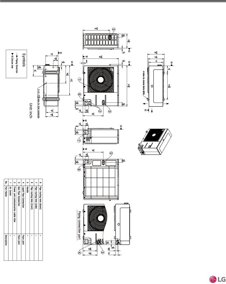
LUU188HV, LUU248HV
Dimensions for LUU188HV, LUU248HV
Figure 4: LUU188HV, LUU248HV Unit Dimensions.
Single Zone Vertical Air Handling Unit Engineering Manual
16 | PRODUCT DATA |
Due to our policy of continuous product innovation, some specifications may change without notification. |
|
©LG Electronics U.S.A., Inc., Englewood Cliffs, NJ.All rights reserved. “LG” is a registered trademark of LG Corp. |
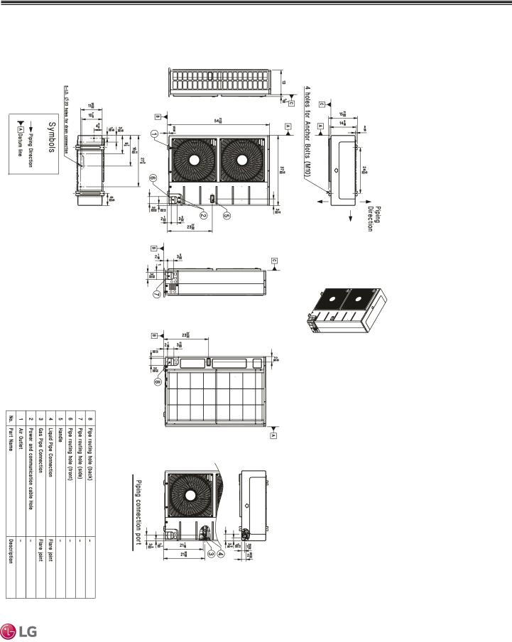
OUTDOOR UNIT DIMENSIONS
LUU368HV, LUU428HV, LUU488HV
Dimensions for LUU368HV, LUU428HV, LUU488HV
Figure 5: LUU368HV, LUU428HV, LUU488HV Unit Dimensions.
Data Product
Due to our policy of continuous product innovation, some specifications may change without notification. |
PRODUCT DATA | 17 |
©LG Electronics U.S.A., Inc., Englewood Cliffs, NJ.All rights reserved. “LG” is a registered trademark of LG Corp. |
|
INDOOR UNIT DIMENSIONS
LVN180HV4, LVN240HV4
Dimensions for LVN180HV4, LVN240HV4 (NJ frame)
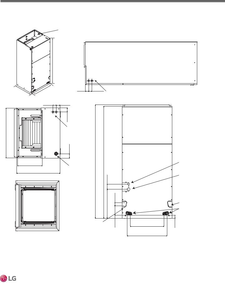
Figure 6: LVN180HV4, LVN240HV4 Indoor Unit Dimensions.
Supply Air opening
Handling Unit Engineering Manual |
18 |
17 |
Single Zone Vertical Air |
|
|
48-11/16
21-1/4 |
18 |
1-5/8 |
|
|
1-9/16 |
1-15/16 |
|
|
2-1/16 |
|
|
7/8” Wiring |
|
|
knockouts |
|
|
2-1/8 |
12-1/8 |
1-15/16 |
1-11/16” Wiring |
|
21-1/4 |
knockouts |
|
|
TOP VIEW
Return Air opening
BOTTOM VIEW
1-9/16 |
7/8” Wiring |
|
knockouts |
5/16-49 |
11/16-48 |
|
|
9/16-2 |
|
|
5/16-14 |
1/2-1 |
|
-4 |
|
|
|
11/16 |
Drain connection for horizontal left application
SIDE VIEW
9-15/16
13
Unit: inches
Note: All measurements FRONT VIEW have a tolerance of ±1/4 in.
Liquid pipe
Vapor pipe
Drain connection for horizontal right 


 application
/1 6-1 9
18 | PRODUCT DATA |
Due to our policy of continuous product innovation, some specifications may change without notification. |
|
©LG Electronics U.S.A., Inc., Englewood Cliffs, NJ.All rights reserved. “LG” is a registered trademark of LG Corp. |
INDOOR UNIT DIMENSIONS
LVN360HV4, LVN420HV, LVN480HV
Dimensions for LVN360HV4, LVN420HV, LVN480HV (NK frame)
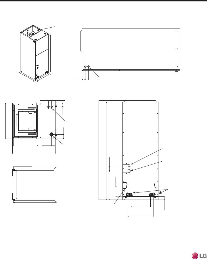
Figure 7: LVN360HV4, LVN420HV, LVN480HV Indoor Unit Dimensions.
Supply Air opening
55-3/16
|
21-1/4 |
25 |
1-5/8 |
1-9/16 |
7/8” Wiring |
SIDE VIEW |
|
|
|
|
|
|
knockouts |
|
|
||
|
|
1-9/16 |
1-15/16 |
|
|
|
|
|
|
|
|
2-1/16 |
|
|
|
|
|
25 |
|
|
7/8” Wiring |
|
|
|
|
|
24 |
|
knockouts |
|
|
|
|
|
|
|
|
|
2-3/16 |
|
|
|
|
|
|
|
12-1/8 |
|
13/16-55 |
3/16-55 |
|
|
Liquid pipe |
|
|
21-1/4 |
1-11/16” Wiring |
|
|
|
|
|
|
|
knockouts |
|
|
|
|
Vapor pipe |
|
|
|
|
|
|
9/16-2 |
|
|
|
|
|
|
|
|
|
|
|
|
|
|
|
|
|
|
-1 |
|
Drain connection |
|
|
|
|
|
14 |
1/2 |
|
for horizontal right |
|
|
|
|
|
|
application |
||
|
|
Return Air |
|
|
1/4- |
|
|
|
|
|
|
|
|
|
Drain connection |
||
|
|
opening |
|
|
|
|
|
|
|
|
|
|
|
|
|
|
for upflow application |
|
|
|
|
|
|
11/16-4 |
|
1 |
|
|
|
|
Drain connection |
16-15/16 |
9/16- |
||
|
|
|
|
for horizontal left |
|
|
|
|
|
|
|
|
application |
|
|
20 |
|
|
|
Unit: inches |
|
|
|
|
|
|
|
|
|
|
|
|
FRONT VIEW |
|
|
|
|
Note: All measurements |
|
|
|
|
|
|
have a tolerance of ±1/4 in.
Data Product
Due to our policy of continuous product innovation, some specifications may change without notification. |
PRODUCT DATA | 19 |
©LG Electronics U.S.A., Inc., Englewood Cliffs, NJ.All rights reserved. “LG” is a registered trademark of LG Corp. |
|
Single Zone Vertical Air Handling Unit Engineering Manual
ACOUSTIC DATA
Indoor Units
Indoor Unit Sound Pressure Measurement
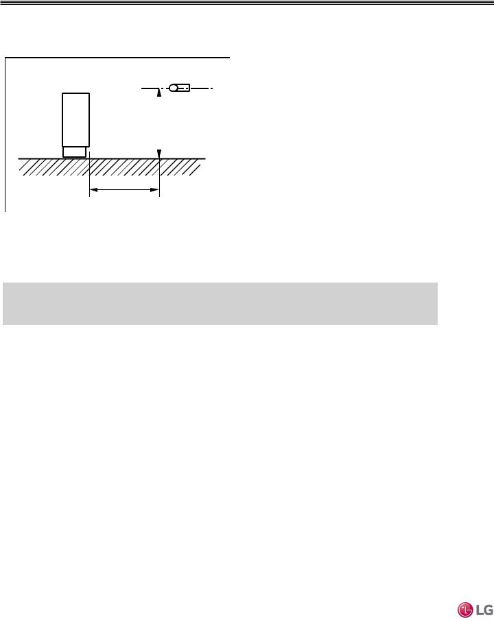
Figure 8: Sound Pressure Measurement Location.
Microphone
3.3ft
3.3ft |
•Measurements are taken 3.3 ft away from the front of the unit.
•Sound pressure levels are measured in dB(A) with a tolerance of ±3.
•Sound pressure levels are tested in an anechoic chamber under ISO Standard 3745.
Operating Conditions:
•Power source: 220V/60 Hz
•Sound level will vary depending on a range of factors including the construction (acoustic absorption coefficient) of a particular room in which the unit was installed.
Indoor Unit Sound Pressure Levels
Table 7: Vertical Air Handling Unit Indoor Unit Sound Pressure Levels.
Model |
|
Sound Pressure Levels dB(A) |
|
|
|
High Fan Speed |
|
Medium Fan Speed |
Low Fan Speed |
NJ Frames |
|
|
|
|
LVN180HV4 |
42 |
|
42 |
41 |
LVN240HV4 |
43 |
|
42 |
41 |
NK Frames |
|
|
|
|
LVN360HV4 |
45 |
|
44 |
43 |
LVN420HV |
48 |
|
45 |
44 |
LVN480HV |
49 |
|
48 |
44 |
20 | PRODUCT DATA |
Due to our policy of continuous product innovation, some specifications may change without notification. |
|
©LG Electronics U.S.A., Inc., Englewood Cliffs, NJ.All rights reserved. “LG” is a registered trademark of LG Corp. |

ACOUSTIC DATA
Indoor Units
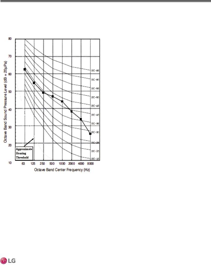
LVN180HV4, LVN240HV4 Sound Pressure Diagrams
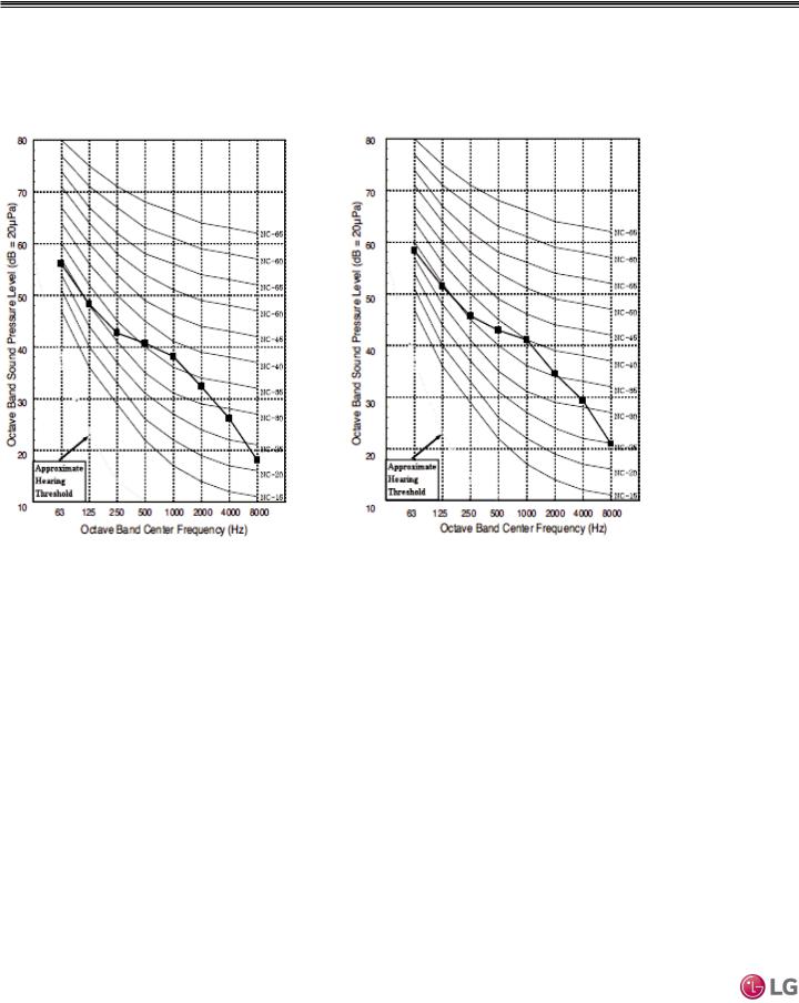
Figure 9: LVN180HV4 and LVN240HV4 Sound Pressure Level Diagrams. |
|
LVN180HV4 |
LVN240HV4 |
Data Product
Due to our policy of continuous product innovation, some specifications may change without notification. |
PRODUCT DATA | 21 |
©LG Electronics U.S.A., Inc., Englewood Cliffs, NJ.All rights reserved. “LG” is a registered trademark of LG Corp. |
|
ACOUSTIC DATA
Indoor Units
LVN360HV4, LVN420HV Sound Pressure Diagrams
Figure 10: LVN360HV4 and LVN420HV Sound Pressure Level Diagrams. |
|
LVN360HV4 |
LVN420HV |
Single Zone Vertical Air Handling Unit Engineering Manual
22 | PRODUCT DATA |
Due to our policy of continuous product innovation, some specifications may change without notification. |
|
©LG Electronics U.S.A., Inc., Englewood Cliffs, NJ.All rights reserved. “LG” is a registered trademark of LG Corp. |
INDOOR ACOUSTIC DATA
Indoor Units
LVN480HV Sound Pressure Diagrams
Figure 11: LVN480HV Sound Pressure Level Diagrams.
LVN480HV
Data Product
Due to our policy of continuous product innovation, some specifications may change without notification. |
PRODUCT DATA | 23 |
©LG Electronics U.S.A., Inc., Englewood Cliffs, NJ.All rights reserved. “LG” is a registered trademark of LG Corp. |
|
Single Zone Vertical Air Handling Unit Engineering Manual
ACOUSTIC DATA
Indoor Units
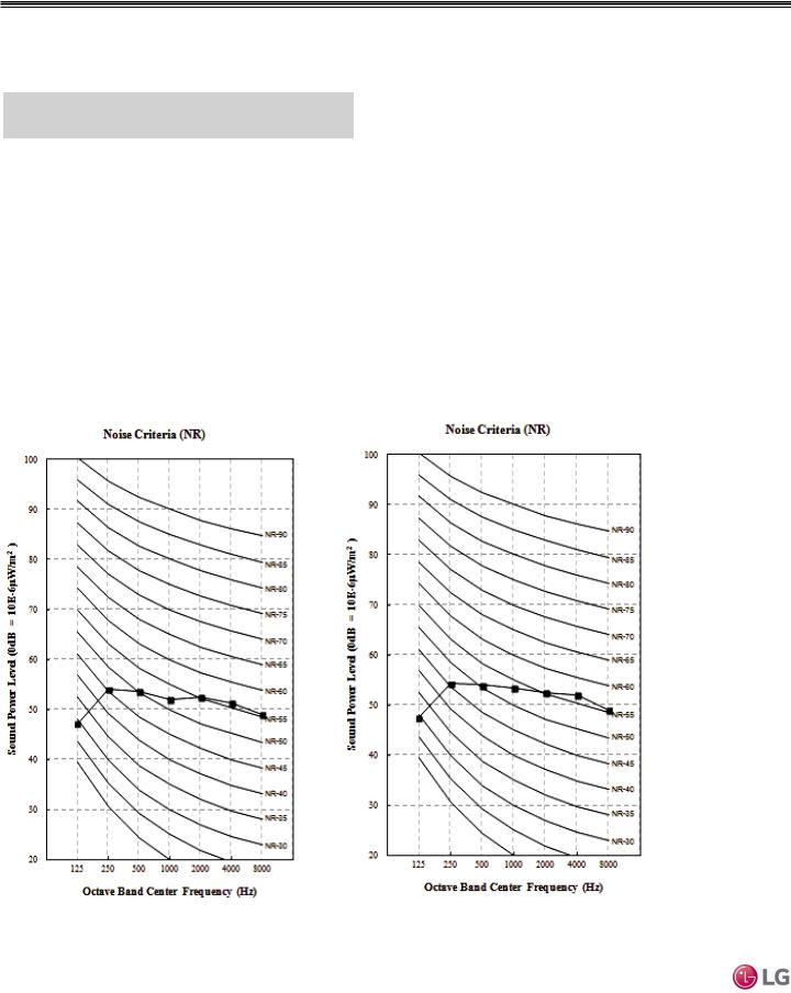
Sound Power Levels
Table 8: Vertical Air Handling Unit Sound Power Levels.
Indoor Unit Model |
Sound Power Levels dB(A) |
|
High Fan Speed |
NJ Frames |
|
LVN180HV4 |
59 |
LVN240HV4 |
60 |
NK Frames |
|
LVN360HV4 |
61 |
LVN420HV |
61 |
LVN480HV |
62 |
•Data is valid under diffuse field conditions.
•Data is valid under nominal operating conditions.
•Sound power level is measured using rated conditions, and tested in a reverberation room per ISO 3741 standards.
•Sound level will vary depending on a range of factors such as construction (acoustic absorption coefficient) of particular area in which the equipment is installed.
•Reference acoustic intensity: 0dB = 10E-6μW/m2
Sound Power Level Diagrams for LVN180HV4 and LVN240HV4
Figure 12: LVN180HV4 and LVN240HV4 Sound Power Level Diagrams. |
|
LVN180HV4 |
LVN240HV4 |
24 | PRODUCT DATA |
Due to our policy of continuous product innovation, some specifications may change without notification. |
|
©LG Electronics U.S.A., Inc., Englewood Cliffs, NJ.All rights reserved. “LG” is a registered trademark of LG Corp. |
ACOUSTIC DATA
Indoor Units
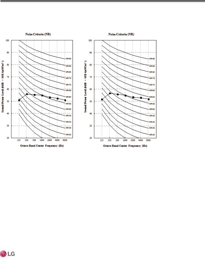
Sound Power Level Diagrams for LVN360HV4 and LVN420HV
Figure 13: LVN360HV4 and LVN420HV Sound Power Level Diagrams. |
|
LVN360HV4 |
LVN420HV |
Data Product
Due to our policy of continuous product innovation, some specifications may change without notification. |
PRODUCT DATA | 25 |
©LG Electronics U.S.A., Inc., Englewood Cliffs, NJ.All rights reserved. “LG” is a registered trademark of LG Corp. |
|
 Loading...