


47LD750
LCD TV
SERVICE MANUAL
CAUTION
BEFORE SERVICING THE CHASSIS,
READ THE SAFETY PRECAUTIONS IN THIS MANUAL.
CHASSIS : LD03B
MODEL : 47LD750/750N 47LD750/750N-ZA
MODEL : 47LD780/790 47LD780/790-ZA
MODEL : 47LD751
47LD751-ZB
North/Latin America http://aic.lgservice.com
Europe/Africa http://eic.lgservice.com
Asia/Oceania http://biz.lgservice.com
Internal Use Only
Printed in KoreaP/NO : MFL62863020 (1003-REV00)

- 2 -
LGE Internal Use OnlyCopyright © 2010 LG Electronics. Inc. All rights reserved.
Only for training and service purposes
CONTENTS
CONTENTS .............................................................................................. 2
PRODUCT SAFETY ................................................................................. 3
SPECIFICATION ....................................................................................... 4
ADJUSTMENT INSTRUCTION ................................................................ 7
BLOCK DIAGRAM...................................................................................14
EXPLODED VIEW .................................................................................. 15
SVC. SHEET ...............................................................................................
- 3 -
LGE Internal Use OnlyCopyright © 2010 LG Electronics. Inc. All rights reserved.
Only for training and service purposes
SAFETY PRECAUTIONS
Many electrical and mechanical parts in this chassis have special safety-related characteristics. These parts are identified by in the
Schematic Diagram and Exploded View.
It is essential that these special safety parts should be replaced with the same components as recommended in this manual to prevent
Shock, Fire, or other Hazards.
Do not modify the original design without permission of manufacturer.
General Guidance
An isolation Transformer should always be used during the
servicing of a receiver whose chassis is not isolated from the AC
power line. Use a transformer of adequate power rating as this
protects the technician from accidents resulting in personal injury
from electrical shocks.
It will also protect the receiver and it's components from being
damaged by accidental shorts of the circuitry that may be
inadvertently introduced during the service operation.
If any fuse (or Fusible Resistor) in this TV receiver is blown,
replace it with the specified.
When replacing a high wattage resistor (Oxide Metal Film Resistor,
over 1 W), keep the resistor 10 mm away from PCB.
Keep wires away from high voltage or high temperature parts.
Before returning the receiver to the customer,
always perform an AC leakage current check on the exposed
metallic parts of the cabinet, such as antennas, terminals, etc., to
be sure the set is safe to operate without damage of electrical
shock.
Leakage Current Cold Check(Antenna Cold Check)
With the instrument AC plug removed from AC source, connect an
electrical jumper across the two AC plug prongs. Place the AC
switch in the on position, connect one lead of ohm-meter to the AC
plug prongs tied together and touch other ohm-meter lead in turn to
each exposed metallic parts such as antenna terminals, phone
jacks, etc.
If the exposed metallic part has a return path to the chassis, the
measured resistance should be between 1 MΩ and 5.2 MΩ.
When the exposed metal has no return path to the chassis the
reading must be infinite.
An other abnormality exists that must be corrected before the
receiver is returned to the customer.
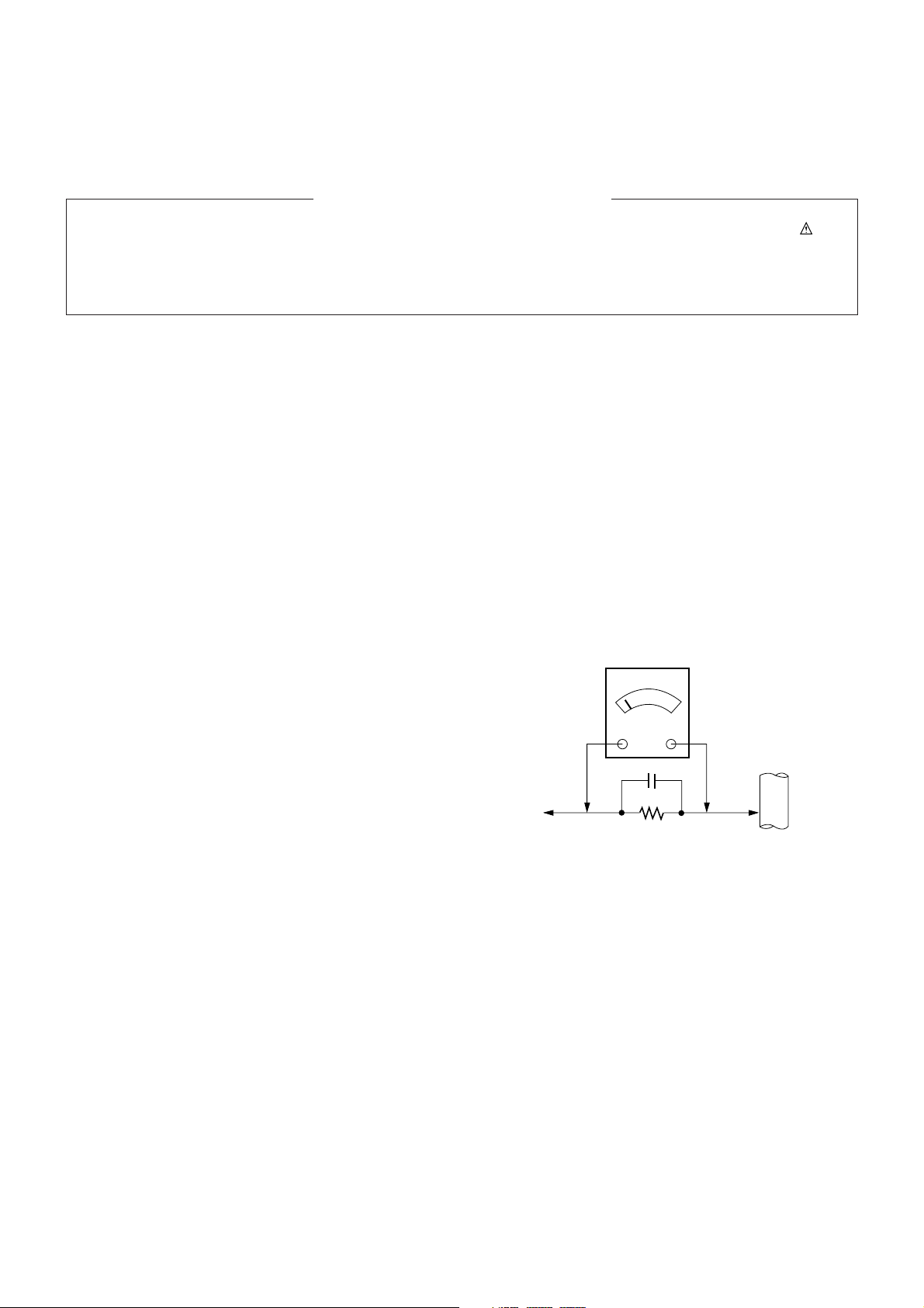
Leakage Current Hot Check (See below Figure)
Plug the AC cord directly into the AC outlet.
Do not use a line Isolation Transformer during this check.
Connect 1.5 K / 10 watt resistor in parallel with a 0.15 uF capacitor
between a known good earth ground (Water Pipe, Conduit, etc.)
and the exposed metallic parts.
Measure the AC voltage across the resistor using AC voltmeter
with 1000 ohms/volt or more sensitivity.
Reverse plug the AC cord into the AC outlet and repeat AC voltage
measurements for each exposed metallic part. Any voltage
measured must not exceed 0.75 volt RMS which is corresponds to
0.5 mA.
In case any measurement is out of the limits specified, there is
possibility of shock hazard and the set must be checked and
repaired before it is returned to the customer.
Leakage Current Hot Check circuit
1.5 Kohm/10W
To Instrument's
exposed
METALLIC PARTS
Good Earth Ground
such as WATER PIPE,
CONDUIT etc.
AC Volt-meter
When 25A is impressed between Earth and 2nd Ground
for 1 second, Resistance must be less than 0.1
*Base on Adjustment standard
IMPORTANT SAFETY NOTICE
0.15 uF
Ω
- 4 -
LGE Internal Use OnlyCopyright © 2010 LG Electronics. Inc. All rights reserved.
Only for training and service purposes
SPECIFICATION
NOTE : Specifications and others are subject to change without notice for improvement
.
1. Application range
This specification is applied to the LCD TV used LD03B
chassis.
2. Requirement for Test
Each part is tested as below without special appointment.
1) Temperature: 25 ºC ± 5 ºC(77 ºF ± 9 ºF), CST: 40 ºC ± 5 ºC
2) Relative Humidity : 65 % ± 10 %
3) Power Voltage
: Standard input voltage (AC 100-240 V~ 50 / 60 Hz)
* Standard Voltage of each products is marked by models.
4) Specification and performance of each parts are followed
each drawing and specification by part number in
accordance with BOM.
5) The receiver must be operated for about 5 minutes prior to
the adjustment.
3. Test method
1) Performance: LGE TV test method followed
2) Demanded other specification
- Safety : CE, IEC specification
- EMC :CE, IEC
4. Module optical specification
1) Stable for approximately 60 minutes in a dark environment at 25 ºC ± 2 ºC and windless room.
2) Operating Ambient Humidity : Min 10, Max 90 %RH
3) Supply Votage : 24 V
4) Frame Frequency : 120 Hz
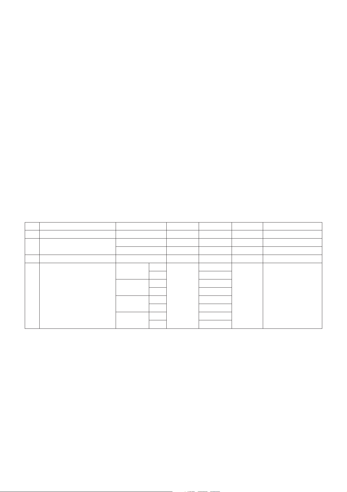
No. Item Specification Min. Typ. Max. Remark
1. Viewing Angle<CR>10> Right/Left/Up/Down 89/89/89/89 CR > 10
2. Luminance Luminance (cd/m
2
) 400 500
Variation 1.3 MAX /MIN
3. Contrast Ratio CR 1100 1500
4. CIE Color Coordinates White Wx 0.279 All white / All black
Wy 0.292
RED Xr 0.636
Yr Typ. 0.335 Typ.
Green Xg -0.03 0.291 +0.03
Yg 0.603
Blue Xb 0.146
Yb 0.061
- 5 -
LGE Internal Use OnlyCopyright © 2010 LG Electronics. Inc. All rights reserved.
Only for training and service purposes
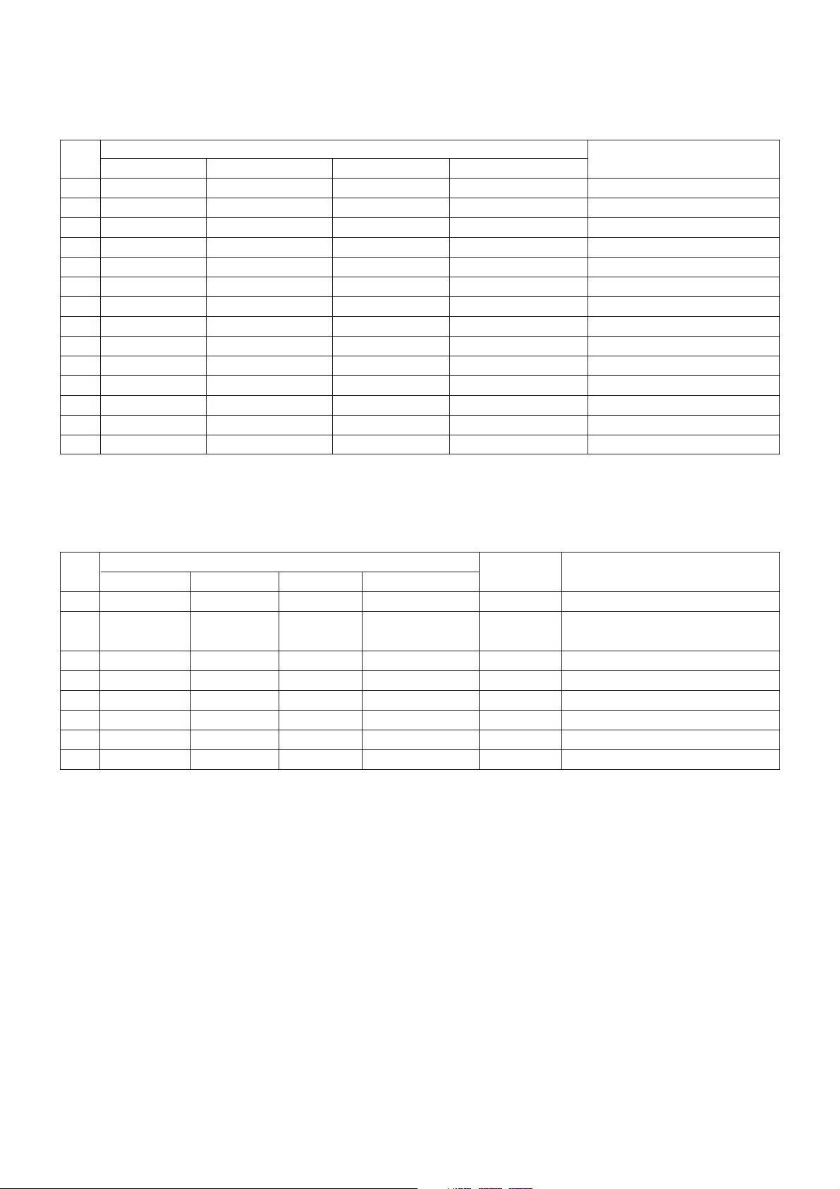
5. Component Video Input (Y, CB/PB, CR/PR)
No.
Specification
Remark
Resolution H-freq(kHz) V-freq(Hz)
1. 720x480 15.73 60.00 SDTV,DVD 480i
2. 720x480 15.63 59.94 SDTV,DVD 480i
3. 720x480 31.47 59.94 480p
4. 720x480 31.50 60.00 480p
5. 720x576 15.625 50.00 SDTV,DVD 625 Line
6. 720x576 31.25 50.00 HDTV 576p
7. 1280x720 45.00 50.00 HDTV 720p
8. 1280x720 44.96 59.94 HDTV 720p
9. 1280x720 45.00 60.00 HDTV 720p
10. 1920x1080 31.25 50.00 HDTV 1080i
11. 1920x1080 33.75 60.00 HDTV 1080i
12. 1920x1080 33.72 59.94 HDTV 1080i
13. 1920x1080 56.250 50 HDTV 1080p
14. 1920x1080 67.5 60 HDTV 1080p
No.
Specification
Proposed Remarks
Resolution H-freq(kHz) V-freq(Hz) Pixel Clock(MHz)
1. 720*400 31.468 70.08 28.321 For only DOS mode
2. 640*480 31.469 59.94 25.17 VESA Input 848*480 60Hz, 852*480 60 Hz
-> 640*480 60 Hz Display
3. 800*600 37.879 60.31 40.00 VESA
4. 1024*768 48.363 60.00 65.00 VESA(XGA)
5. 1280*768 47.78 59.87 79.5 WXGA
6. 1360*768 47.72 59.8 84.75 WXGA
7. 1280*1024 63.595 60.0 108.875 SXGA FHD model
8. 1920*1080 66.587 59.93 138.625 WUXGA FHD model
6. RGB (PC)
- 6 -
LGE Internal Use OnlyCopyright © 2010 LG Electronics. Inc. All rights reserved.
Only for training and service purposes
7. HDMI Input
(1) DTV Mode
No. Resolution H-freq(kHz) V-freq.(Hz) Pixel clock(MHz) Proposed Remark
1. 720*400 31.468 70.08 28.321 HDCP
2. 640*480 31.469 59.94 25.17 VESA HDCP
3. 800*600 37.879 60.31 40.00 VESA HDCP
4. 1024*768 48.363 60.00 65.00 VESA(XGA) HDCP
5. 1280*768 47.78 59.87 79.5 WXGA HDCP
6. 1360*768 47.72 59.8 84.75 WXGA HDCP
7. 1280*1024 63.595 60.0 108.875 SXGA HDCP/FHD model
8. 1920*1080 67.5 60.00 138.625 WUXGA HDCP/FHD model
(2) PC Mode
No. Resolution H-freq(kHz) V-freq.(Hz) Pixel clock(MHz) Proposed Remark
1. 720*480 31.469 /31.5 59.94 /60 27.00/27.03 SDTV 480P
2. 720*576 31.25 50 54 SDTV 576P
3. 1280*720 37.500 50 74.25 HDTV 720P
4. 1280*720 44.96 /45 59.94 /60 74.17/74.25 HDTV 720P
5. 1920*1080 33.72 /33.75 59.94 /60 74.17/74.25 HDTV 1080I
6. 1920*1080 28.125 50.00 74.25 HDTV 1080I
7. 1920*1080 26.97 /27 23.97 /24 74.17/74.25 HDTV 1080P
8. 1920*1080 33.716 /33.75 29.976 /30.00 74.25 HDTV 1080P
9. 1920*1080 56.250 50 148.5 HDTV 1080P
10. 1920*1080 67.43 /67.5 59.94 /60 148.35/148.50 HDTV 1080P
- 7 -
LGE Internal Use OnlyCopyright © 2010 LG Electronics. Inc. All rights reserved.
Only for training and service purposes
ADJUSTMENT INSTRUCTION
1. Application Range
This specification sheet is applied to all of the LCD TV with
LD03B chassis.
2. Designation
(1) Because this is not a hot chassis, it is not necessary to use
an isolation transformer. However, the use of isolation
transformer will help protect test instrument.
(2) Adjustment must be done in the correct order.
(3) The adjustment must be performed in the circumstance of
25 ºC ± 5 ºC of temperature and 65 % ± 10 % of relative
humidity if there is no specific designation.
(4) The input voltage of the receiver must keep AC 100-240
V~ 50 / 60Hz.
(5) The receiver must be operated for about 5 minutes prior to
the adjustment when module is in the circumstance of over
15.
In case of keeping module is in the circumstance of 0 °C, it
should be placed in the circumstance of above 15 °C for 2
hours
In case of keeping module is in the circumstance of below -
20 °C, it should be placed in the circumstance of above 15
°C for 3 hours.
[Caution]
When still image is displayed for a period of 20 minutes or
longer (especially where W/B scale is strong. Digital pattern
13ch and/or Cross hatch pattern 09ch), there can some
afterimage in the black level area.
3. Automatic Adjustment
3.1. ADC Adjustment
(1) Overview
ADC adjustment is needed to find the optimum black level
and gain in Analog-to-Digital device and to compensate
RGB deviation.
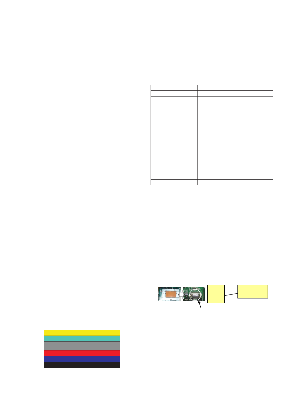
(2) Equipment & Condition
1) Jig (RS-232C protocol)
2) MSPG-925 Series Pattern Generator(MSPG-925FA,
pattern - 65)
- Resolution : 480i Comp1
1080P Comp1
1920*1080 RGB
- Pattern : Horizontal 100% Color Bar Pattern
- Pattern level : 0.7±0.1 Vp-p
- Image
(3) Adjustment
1) Adjustment method
- Using RS-232, adjust items listed in 3.1 in the other
shown in “3.1.(3).3)”
2) Adj. protocol
Ref.) ADC Adj. RS232C Protocol_Ver1.0
3) Adj. order
- aa 00 00 [Enter ADC adj. mode]
- xb 00 40 [Change input source to Component1(No action)]
- ad 00 10 [Adjust 480i Comp1]
- ad 00 10 [Adjust 1080p Comp1]
- xb 00 60 [Change input source to RGB(No action)]
- ad 00 10 [Adjust 1080p RGB]
- ad 00 90 End adj.
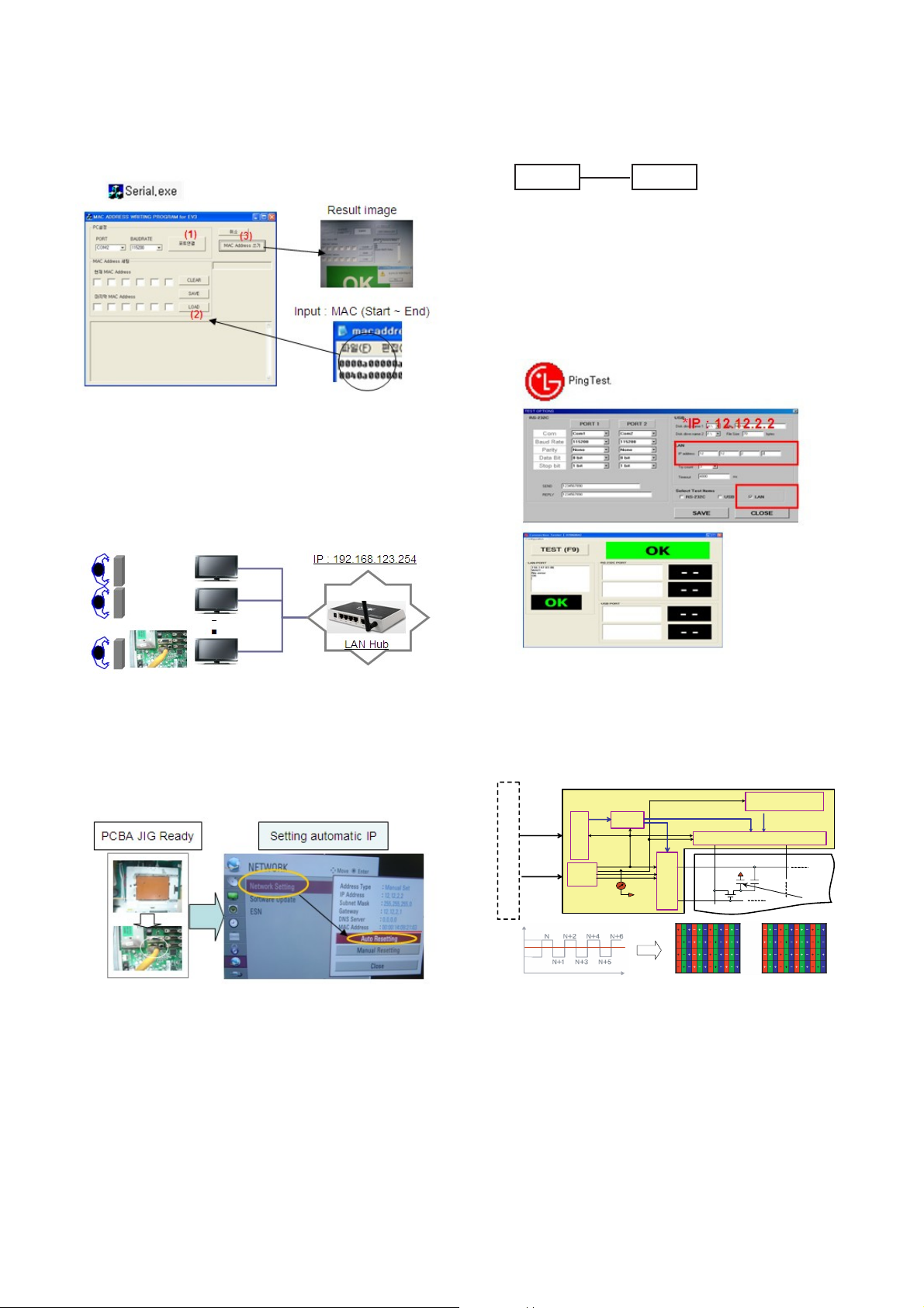
3.2. MAC Address Write
(1) Equipment & Condition
- Play file: Serial.exe
- MAC Address edit
- Input Start / End MAC address
(2) Download method
1) Communication Prot connection
Connect: PCBA Jig-> RS-232C Port== PC-> RS-232C Port
Protocol Command Set ACK
Enter adj. mode aa 00 00 a 00 OK00x
Source change xb 00 40 b 00 OK40x (Adjust 480i Comp1 )
(Adjust 1080p Comp1)
xb 00 60 b 00 OK60x (Adjust 1080p RGB)
Begin adj. ad 00 10
Return adj. result OKx (Case of Success)
NGx (Case of Fail)
Read adj. data (main) (main: component1 480i, RGB 1080p)
ad 00 20 000000000000000000000000007c007b006dx
(main) (main: component1 108p)
ad 00 30 000000070000000000000000007c00830077x
Confirm adj. ad 00 99 NG 03 00x (Fail)
NG 03 01x (Fail)
NG 03 02x (Fail)
OK 03 03x (Success)
End adj. aa 00 90 a 00 OK90x
PCBA
PC(RS-232C)
RS-232C Por t
- 8 -
LGE Internal Use OnlyCopyright © 2010 LG Electronics. Inc. All rights reserved.
Only for training and service purposes
2) MAC Address Download
- Com 1,2,3,4 and 115200(Baud rate)
- Port connection button click(1)
- Load button click(2) for MAC Address write.
- Start MAC Address write button(3)
- Check the OK or NG
3.3. LAN
(1) Equipment & Condition
A Each other connection to LAN Port of IP Hub and Jig
(2) LAN inspection solution
A LAN Port connection with PCB
A Network setting at MENU Mode of TV
A setting automatic IP
A Setting state confirmation
-> If automatic setting is finished, you confirm IP and
MAC Address.
3.4. LAN PORT INSPECTION(PING TEST)
Connect SET -> LAN port == PC -> LAN Port
(1) Equipment setting
1) Play the LAN Port Test PROGRAM.
2) Input IP set up for an inspection to Test
Program.
*IP Number : 12.12.2.2
(2) LAN PORT inspection (PING TEST)
1) Play the LAN Port Test Program.
2) Connect each other LAN Port Jack.
3) Play Test (F9) button and confirm OK Message.
4) Remove LAN CABLE
3.5. V-COM Adjust(Only LGD(M+S) Module)
- Why need Vcom adjustment?
A The Vcom (Common Voltage) is a Reference Voltage of
Liquid Crystal Driving.
-> Liquid Crystal need for Polarity Change with every frame.
Row Li ne
Column Li ne
CLC
CST
Pane l
S
Y
S
T
E
M
Gat e Driv e IC
So urce D r iv e I C
Circuit Block
Tim i ng
Cont r o ll er
Po w er
Blo ck
V
COM
Gamma
Ref er ence V o ltage
Gamm a Reference
Volta ge
Data (R,G ,B) & C on tro l signal
Cont rol si gnal
Data (R,G,B ) &
Cont rol si gnal
In t er fa ce
TFT
Po w er I np ut
Power Input
Da ta I n pu t
Da ta I n pu t
V
COM
Liquid
Crys tal
V
COM
SET PC
- 9 -
LGE Internal Use OnlyCopyright © 2010 LG Electronics. Inc. All rights reserved.
Only for training and service purposes
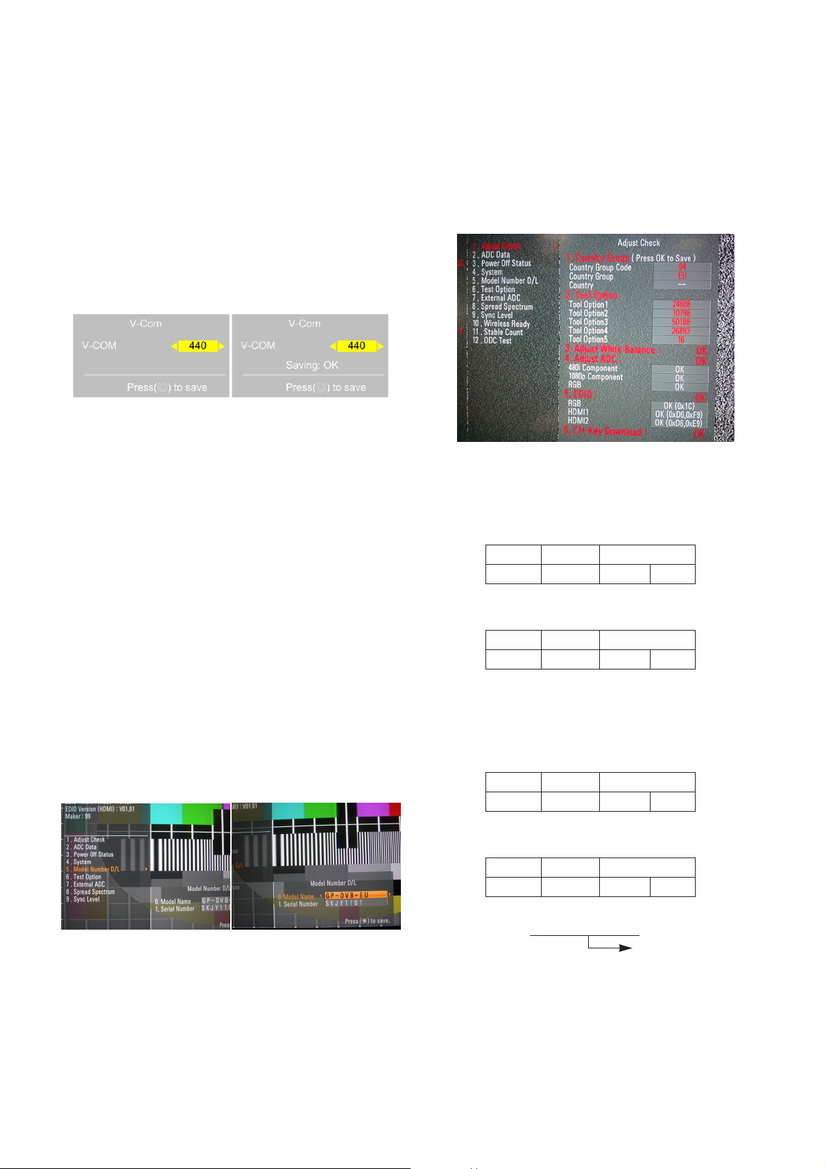
- Adjust sequence
A Press the PIP key of the ADJ remote control.(This PIP key
is hot key to enter the VCOM adjusting mode)
(Or After enter Service Mode by pushing “ADJ” key, then
Enter V-Com Adjust mode by pushing “G” key at “10. V-
Com”)
A As pushing the right or the left button on the remote
control, and find the V-COM value Which is no or
minimized the Flicker.
(If there is no flicker at default value, Press the exit key
and finish the VCOM adjustment.)
A Push the OK key to store value. Then the message
“Saving OK” is pop.
A Press the exit key to finish VCOM adjustment.
3.6. Model name & serial number download
(1) Model name & Serial number D/L
A Press “Power on” key of service remote control.(Baud
rate : 115200 bps)
A Connect RS232 Signal Cable to RS-232 Jack.
A Write Serial number by use RS-232.
A Must check the serial number at Instart menu.
(2) Method & notice
A. Serial number D/L is using of scan equipment.
B. Setting of scan equipment operated by Manufacturing
Technology Group.
C.Serial number D/L must be conformed when it is
produced in production line, because serial number D/L
is mandatory by D-book 4.0
* Manual Download (Model Name and Serial Number)
If the TV set is downloaded by OTA or service man,
sometimes model name or serial number is initialized.(Not
always)
There is impossible to download by bar code scan, so It
need Manual download.
a. Press the ‘instart’ key of ADJ remote control.
b. Go to the menu ‘5.Model Number D/L’ like below photo.
c. Input the Factory model name(ex 42LD450-ZA) or Serial
number like photo.
d. Check the model name Instart menu -> Factory name
displayed (ex 42LE7500-ZA)
e. Check the Diagnostics (DTV country only) -> Buyer model
displayed (ex 42LE7500-ZA)
3.7. CI+ Key Download method
(1) Download Procedure
1) Press "Power on" button of a service R/C.(Baud rate :
115200 bps)
2) Connect RS232-C Signal Cable.
3) Write CI+ Key through RS-232-C.
4) Check whether the key was downloaded or not at ‘In
Start’ menu. (Refer to below).
=> Check the Download to CI+ Key value in LGset.
1. check the method of CI+ Key value
a. check the method on Instart menu
b. check the method of RS232C Command
1) into the main ass’y mode (RS232 : aa 00 00)
2) check the key download for transmitted command
(RS232 : ci 00 10)
3) result value
- normally status for download : OKx
- abnormally status for download : NGx
2. Check the method of CI+ Key value (RS232)
1) into the main ass’y mode (RS232 : aa 00 00)
2) Check the method of CI+ key by command (RS232 :
ci 00 20)
3) Result value
i 01 OK 1d1852d21c1ed5dcx
[Visual Adjust and control the Voltage level]
CMD 1 CMD 2 Data 0
AA00
CMD 1 CMD 2 Data 0
CI10
CMD 1 CMD 2 Data 0
AA00
CMD 1 CMD 2 Data 0
CI20
CI+ key Value
- 10 -
LGE Internal Use OnlyCopyright © 2010 LG Electronics. Inc. All rights reserved.
Only for training and service purposes
4. Manual Adjustment
4.1. ADC(Saturn5) Adjustment
4.1.1. Overview
ADC adjustment is needed to find the optimum black level and
gain in Analog-to-Digital device and to compensate RGB
deviation.
4.1.2. Equipment & Condition
(1) Adjust Remote control
(2) 801GF(802B, 802F, 802R) or MSPG925FA Pattern
Generator
- Resolution :
480i Comp1(MSPG-925FA : Model-209, Pattern-65)
1080p Comp1(MSPG-925FA : Model-225, Pattern-65)
1080p RGB (MSPG-925FA : Model-225, Pattern-65)
- Pattern : Horizontal 100% Color Bar Pattern
- Pattern level: 0.7 ± 0.1 Vp-p
- Image
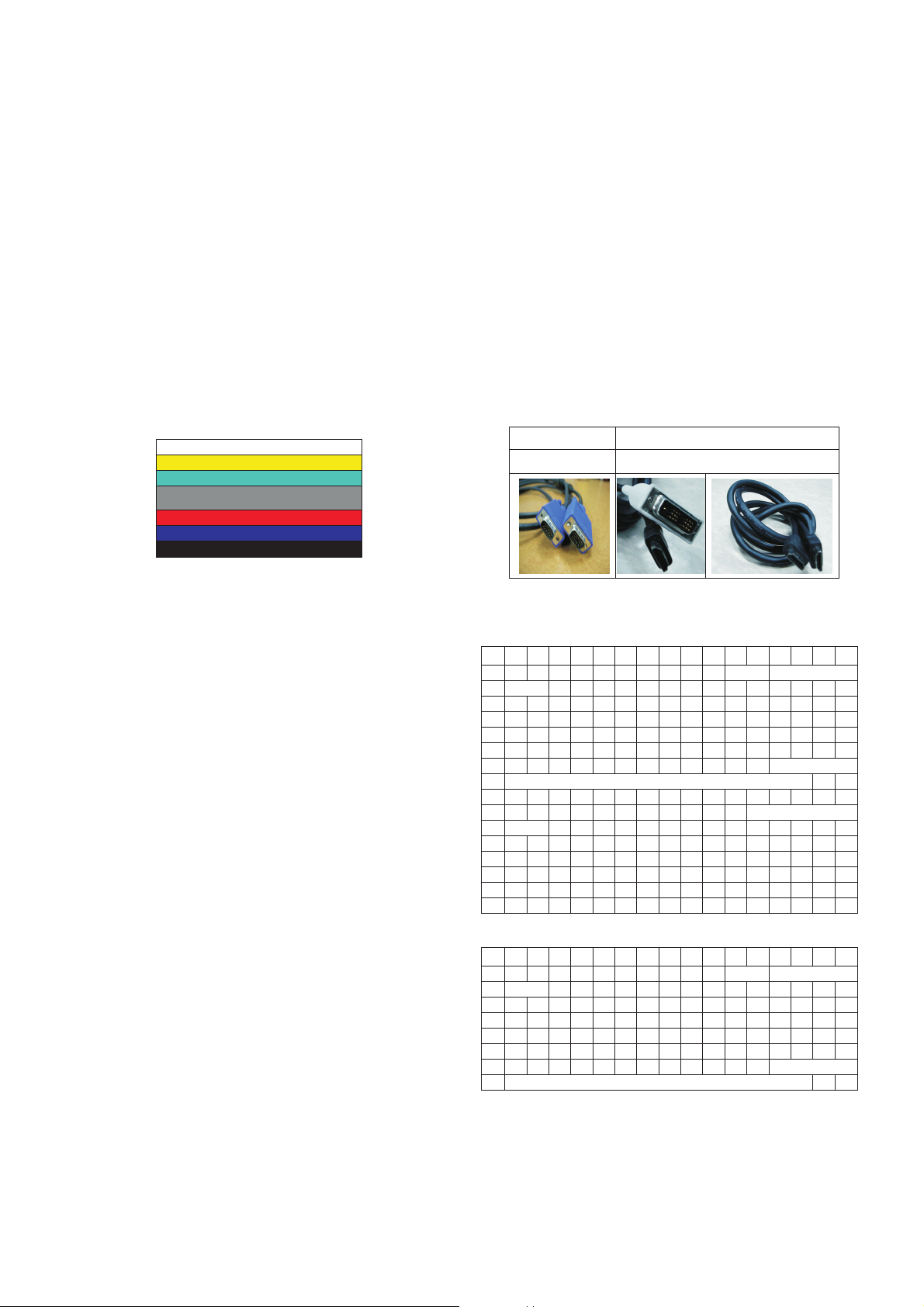
(3) Must use standard cable
4.1.3. Adjust method
(1) ADC 480i/1080p Comp1, RGB
1) Check connected condition of Comp1 cable to the equipment.
2) Give a 480i, 1080p Mode, Horizontal 100% Color Bar
Pattern to Comp1.
(MSPG-925FA -> Model: 209, Pattern: 65)
3) Change input mode as Component1 and picture mode
as “Standard”
4) Press the In-start Key on the ADJ remote after at least 1
min of signal reception. Then, select 7. External ADC ->
1. COMP 1080p on the menu.
5) Press OK in Comp480i menu.
6) Give a 1080p Mode, Horizontal 100% Color Bar Pattern
to Comp1. (MSPG-925A -> Model: 225, Pattern: 65)
7) Press OK in Comp 1080p menu.
8) Press OK in RGB menu.
9) If ADC Comp is successful, “ADC Component Success”
is displayed. If ADC calibration is failure, “ADC
Component Fail” is displayed.
10) If ADC calibration is failure, after recheck ADC pattern
or condition, retry calibration
11) If ADC RGB is successful, “ADC RGB Success” is
displayed. If ADC calibration is failure, “ADC RGB Fail”
is displayed.
12) If ADC calibration is failure, after recheck ADC pattern
or condition, retry calibration
4.2. EDID(The Extended Display Identification
Data)/DDC(Display Data Channel) download
(1) Overview
It is a VESA regulation. A PC or a MNT will display an
optimal resolution through information sharing without any
necessity of user input. It is a realization of “Plug and Play”.
(2) Equipment
- Adjust remote control
- Since embedded EDID data is used, EDID download JIG,
HDMI cable and D-sub cable are not need.
(3) Download method
1) Press Adj. key on the Adj. R/C,
2) Select EDID D/L menu.
3) By pressing Enter key, enter EDID D/L menu.
4) If Download is successful, OK is displayed, but If
Download is failure, NG is displayed.
5) If Download is failure, Re-try download.
(4) EDID DATA
A HDMI
A RGB
* Address 10/11 and 7F means Manufacture Week and
Checksum. So this data will be change.
D-sub to D-sub DVI-D to HDMI or HDMI to HDMI
For HDMI EDIDFor Analog EDID
0x00 0x01 0x02 0x03 0x04 0x05 0x06 0x07 0x08 0x09 0x0A 0x0B 0x0C0x0D 0x0E 0x0F
0x00 00 FF FF FF FF FF FF 00 1E 6D
ⓐⓑ
0x01 ⓒ 01 03 80 10 09 78 0A EE 91 A3 54 4C 99 26
0x02 0F 50 54 A1 08 00 71 4F 81 80 01 01 01 01 01 01
0x03 01 01 01 01 01 01 02 3A 80 18 71 38 2D 40 58 2C
0x04 45 00 A0 5A 00 00 00 1E 01 1D 00 72 51 D0 1E 20
0x05 6E 28 55 00 A0 5A 00 00 00 1E 00 00 00 FD 00 3A
0x06 3E 1E 53 10 00 0A 20 20 20 20 20 20 ⓓ
0x07 ⓓ 01 ⓔ
0x00 02 03 26 F1 4E 10 1F 84 13 05 14 03 02 12 20 21
0x01 22 15 01 26 15 07 50 09 57 07 67 ⓕ
0x02 ⓕ E3 05 03 01 01 1D 80 18 71 1C 16 20 58 2C
0x03 25 00 A0 5A 00 00 00 9E 01 1D 00 80 51 D0 0C 20
0x04 40 80 35 00 A0 5A 00 00 00 1E 02 3A 80 18 71 38
0x05 2D 40 58 2C 45 00 A0 5A 00 00 00 1E 66 21 50 B0
0x06 51 00 1B 30 40 70 36 00 A0 5A 00 00 00 1E 00 00
0x07 00 00 00 00 00 00 00 00 00 00 00 00 00 00 01 ⓔ
0x00 0x01 0x02 0x03 0x04 0x05 0x06 0x07 0x08 0x09 0x0A 0x0B 0x0C0x0D 0x0E 0x0F
0x00 00 FF FF FF FF FF FF 00 1E 6D ⓐⓑ
0x01 ⓒ 01 03 68 10 09 78 0A EE 91 A3 54 4C 99 26
0x02 0F 50 54 A1 08 00 81 80 61 40 45 40 31 40 01 01
0x03 01 01 01 01 01 01 02 3A 80 18 71 38 2D 40 58 2C
0x04 45 00 A0 5A 00 00 00 1E 01 1D 00 72 51 D0 1E 20
0x05 6E 28 55 00 A0 5A 00 00 00 1E 00 00 00 FD 00 3A
0x06 3E 1E 53 10 00 0A 20 20 20 20 20 20 ⓓ
0x07 ⓓ 00 ⓔ
- 11 -
LGE Internal Use OnlyCopyright © 2010 LG Electronics. Inc. All rights reserved.
Only for training and service purposes
- Detail EDID Options are below
ⓐ Product ID
ⓑ Serial No. : Controlled on product line
ⓒ Month, Year: Controlled on production line:
ex) Monthly : ‘02’ -> ‘02’
Year : ‘2009’ -> ‘13’
ⓓ Model Name(Hex):
ⓔ Checksum(Model: LG TV)
ⓕ Vendor Specific(HDMI)
4.3. White Balance Adjustment
4.3.1 Overview
- W/B adj. Objective & How-it-works
(1) Objective: To reduce each Panel’s W/B deviation
(2) How-it-works : When R/G/B gain in the OSD is at 192, it
means the panel is at its Full Dynamic Range. In order to
prevent saturation of Full Dynamic range and data, one
of R/G/B is fixed at 192, and the other two is lowered to
find the desired value.
(3) Adj. condition : normal temperature
1) Surrounding Temperature : 25 ºC ± 5 ºC
2) Warm-up time: About 5 Min
3) Surrounding Humidity : 20 % ~ 80 %
4.3.2 Equipment
1) Color Analyzer: CA-210 (NCG: CH9 / WCG: CH 12)
2) Adj. Computer(During auto adj., RS-232C protocol is needed)
3) Adjust Remote control
4) Video Signal Generator MSPG-925F 720p/216-Gray
(Model:217, Pattern:78)
-> Only when internal pattern is not available
A Color Analyzer Matrix should be calibrated using CS-1000
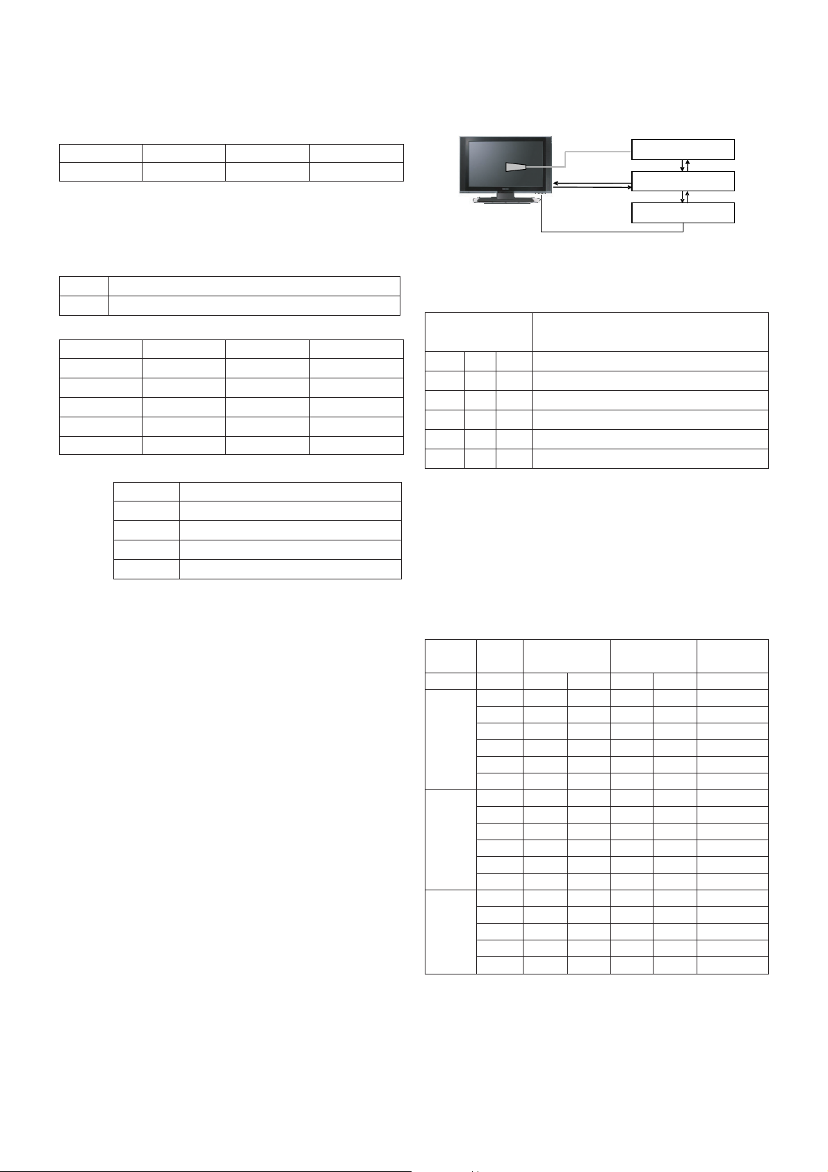
4.3.3. Equipment connection MAP
4.3.4. Adj. Command (Protocol)
A RS-232C Command used during auto-adj.
Ex) wb 00 00 -> Begin white balance auto-adj.
wb 00 10 -> Gain adj.
ja 00 ff -> Adj. data
jb 00 c0
...
...
wb 00 1f -> Gain adj. completed
*(wb 00 20(Start), wb 00 2f(completed)) -> Off-set adj.
wb 00 ff -> End white balance auto-adj.
A Adj. Map
Model Name HEX EDID Table DDC Function
FHD Model 0001 01 00 Analog/Digital
MODEL MODEL NAME(HEX)
all 00 00 00 FC 00 4C 47 20 54 56 0A 20 20 20 20 20 20 20
INPUT MODEL NAME(HEX)
HDMI1 67 03 0C 00 10 00 B8 2D
HDMI2 67 03 0C 00 20 00 B8 2D
HDMI3 67 03 0C 00 30 00 B8 2D
HDMI4 67 03 0C 00 40 00 B8 2D
Color Analyzer
Comp uter
Pattern Generator
RS- 232C
RS-232C
RS-232C
Probe
Signal Source
* If TV internal pattern is used, not needed
RS-232C COMMAND Explanation
[CMD ID DATA]
wb 00 00 Begin White Balance adj.
wb 00 10 Gain adj.(internal white pattern)
wb 00 1f Gain adj. completed
wb 00 20 Offset adj.(internal white pattern)
wb 00 2f Offset adj. completed
wb 00 ff End White Balance adj.(Internal pattern disappears)
ITEM Command Data Range Default
(Hex.) (Decimal)
Cmd 1 Cmd 2 Min Max
Cool R-Gain j g 00 C0
G-Gain j h 00 C0
B-Gain j i 00 C0
R-Cut
G-Cut
B-Cut
Medium R-Gain j a 00 C0
G-Gain j b 00 C0
B-Gain j c 00 C0
R-Cut
G-Cut
B-Cut
Warm R-Gain j d 00 C0
G-Gain j e 00 C0
B-Gain j f 00 C0
R-Cut
G-Cut
ⓔ1 ⓔ2 ⓔ3
HDMI 1 D7 D9 X
HDMI 2 D7 C9 X
HDMI 3 D7 B9 X
HDMI 4 X X X
RGB X X 1D
- 12 -
LGE Internal Use OnlyCopyright © 2010 LG Electronics. Inc. All rights reserved.
Only for training and service purposes
4.3.5. Adj. method
(1) Auto adj. method
1) Set TV in adj. mode using POWER ON key.
2) Zero calibrate probe then place it on the center of the
Display.
3) Connect Cable (RS-232C)
4) Select mode in adj. Program and begin adjustment.
5) When adj. is complete (OK Sing), check adj. status pre
mode. (Warm, Medium, Cool)
6) Remove probe and RS-232C cable to complete adj.
A W/B Adj. must begin as start command “wb 00 00” , and
finish as end command “wb 00 ff”, and Adj. offset if need.
(2) Manual adj. method
1) Set TV in Adj. mode using POWER ON
2) Zero Calibrate the probe of Color Analyzer, then place it
on the center of LCD module within 10cm of the surface.
3) Press ADJ key -> EZ adjust using adj. R/C -> 7. White-
Balance then press the cursor to the right (KEY
G).
(When KEY(
G) is pressed 216 Gray internal pattern will
be displayed)
4) One of R Gain / G Gain / B Gain should be fixed at 192,
and the rest will be lowered to meet the desired value.
5) Adj. is performed in COOL, MEDIUM, WARM 3 modes
of color temperature.
A If internal pattern is not available, use RF input. In EZ
Adj. menu 7.White Balance, you can select one of 2
Test-pattern: ON, OFF. Default is inner(ON). By
selecting OFF, you can adjust using RF signal in 216
Gray pattern.
A Adj. condition and cautionary items
1) Lighting condition in surrounding area
Surrounding lighting should be lower 10 lux. Try to
isolate adj. area into dark surrounding.
2) Probe location
: Color Analyzer (CA-210) probe should be within 10
cm and perpendicular of the module surface (80° ~
100°)
3) Aging time
- After Aging Start, Keep the Power ON status during
5 Minutes.
- In case of LCD, Back-light on should be checked
using no signal or Full-white pattern.
4.3.6. Reference (White Balance Adj. coordinate
and temperature)
A Luminance : 216 Gray
A Standard color coordinate and temperature using CS-1000
(over 26 inch)
A Standard color coordinate and temperature using CA-
210(CH 9)
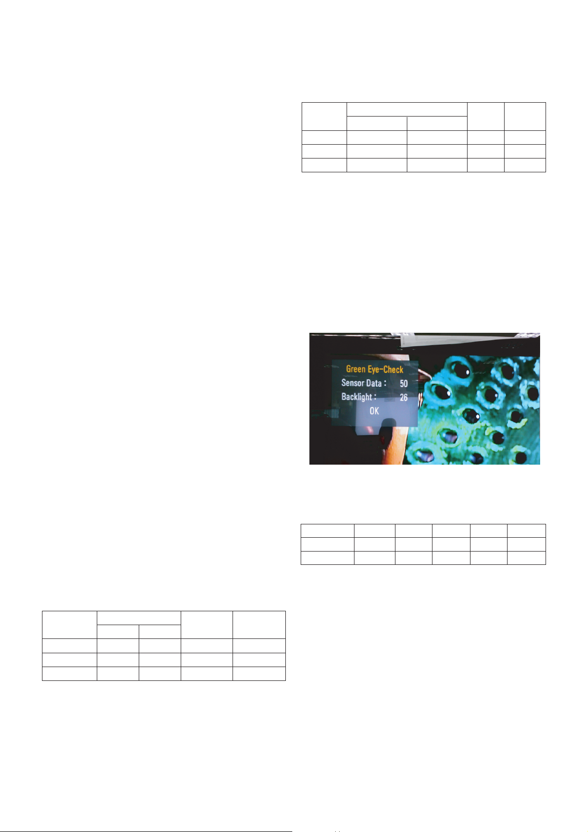
4.4. EYE-Q function check
Step 1) Turn on TV
Step 2) Press EYE key of Adj. R/C
Step 3) Cover the Eye Q II sensor on the front of the using
your hand and wait for 6 seconds
Step 4) Confirm that R/G/B value is lower than 10 of the “Raw
Data (Sensor data, Back light)”. If after 6 seconds,
R/G/B value is not lower than 10, replace Eye Q II
sensor.
Step 5) Remove your hand from the Eye Q II sensor and wait
for 6 seconds.
Step 6) Confirm that “ok” pop up. If change is not seen,
replace Eye Q II sensor.
4.7. Tool Option selection
- Method : Press Adj. key on the Adj. R/C, then select Tool
option.
4.8. Ship-out mode check(In-stop)
After final inspection, press IN-STOP key of the Adj. R/C and
check that the unit goes to Stand-by mode.
After final inspection, Always turn on the Mechanical S/W.
Mode Color Coordination Temp ∆uv
xy
COOL 0.269 0.273 13000 K 0.0000
MEDIUM 0.285 0.293 9300 K 0.0000
WARM 0.313 0.329 6500 K 0.0000
Mode Color Coordination Temp ∆uv
xy
COOL 0.269 ± 0.002 0.273 ± 0.002 13000 K 0.0000
MEDIUM 0.285 ± 0.002 0.293 ± 0.002 9300 K 0.0000
WARM 0.313 ± 0.002 0.329 ± 0.002 6500 K 0.0000
MODEL Tool 1 Tool 2 Tool 3 Tool 4 Tool 5
47LD750 32899 23087 56332 22828 2866
47LD790 32899 23087 56332 20780 2866
 Loading...