


 Loading...
LG 37LK450, 32LK330, 32LK450, 42PT250E, 42PW350E Owner's Manual
...OWNER’S MANUAL
LED LCD TV / LCD TV / PLASMA TV
Please read this manual carefully before operating the set and retain it for future reference.
LED LCD TV MODELS |
LCD TV MODELS |
PLASMA TV MODELS |
|||
19LV2500 |
32LV3500 |
22LK330 |
32LK450 |
42PT250E |
42PW350E |
22LV2500 |
37LV3500 |
26LK330 |
37LK450 |
50PT250E |
50PW350E |
26LV2500 |
42LV3500 |
32LK330 |
42LK450 |
42PT260E |
50PV550E |
32LV2500 |
47LV3500 |
|
|
50PT260E |
60PV550E |
32LV3400 |
42LV4500 |
|
|
|
|
42LV3400 |
47LV4500 |
|
|
|
|
|
32LW4500 |
|
|
|
|
|
42LW4500 |
|
|
|
|
|
47LW4500 |
|
|
|
www.lg.com |
P/NO : SAC34134224 (1108-REV04) |
|
|
|
||
<![endif]>ENGLISH
2 LICENSES
LICENSES
Supported licenses may differ by model. For more information about licenses, visit www.lg.com.
Manufactured under license from Dolby Laboratories. “Dolby” and the double-D symbol are trademarks of Dolby Laboratories.
HDMI, the HDMI logo and High-Definition Multimedia Interface are trademarks or registered trademarks of HDMI Licensing LLC.
ABOUT DIVX VIDEO: DivX® is a digital video format created by DivX, Inc. This is an official DivX Certified® device that plays DivX video. Visit www.divx.com for more information and software tools to convert your files into DivX video.
ABOUT DIVX VIDEO-ON-DEMAND: This DivX Certified® device must be registered in order to play purchased DivX Video-on-Demand (VOD) movies. To obtain your registration code, locate the DivX VOD section in your device setup menu. Go to vod.divx.com for more information on how to complete your registration.
“DivX Certified® to play DivX® video up to HD 1080p, including premium content.”
“DivX®, DivX Certified® and associated logos are registered trademarks of DivX, Inc. and are used under license.”
“Covered by one or more of the following U.S. patents: 7,295,673; 7,460,668; 7,515,710; 7,519,274”
 NOTE
NOTE
yyPlasma : Plasma TV |
LCD : LED LCD TV, LCD TV |
yyImage shown may differ from your TV.
yyYour TV’s OSD (On Screen Display) may differ slightly from that shown in this manual.
IMPORTANT SAFETY INSTRUCTIONS 3
IMPORTANT SAFETY INSTRUCTIONS
Always comply with the following precautions to avoid dangerous situations and ensure peak performance of your product.
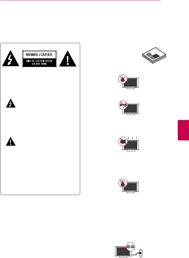
TO REDUCE THE RISK OF ELECTRIC SHOCK DO NOT REMOVE COVER (OR BACK). NO USER SERVICEABLE PARTS INSIDE. REFER TO QUALIFIED SERVICE PERSONNEL.
The lightning flash with arrowhead symbol, within an equilateral triangle, is intended to alert the user to the
presence of uninsulated “dangerous voltage” within the product’s enclosure that may be of sufficient magnitude to constitute a risk of electric shock to persons.
The exclamation point within an
equilateral triangle is intended to alert the user to the presence of important
operating and maintenance (servicing) instructions in the literature accompanying the appliance.
WARNING/CAUTION
-TO REDUCE THE RISK OF FIRE AND ELECTRIC SHOCK, DO NOT EXPOSE THIS PRODUCT TO RAIN OR MOISTURE.
Read these instructions.
Keep these instructions.
Heed all warning.
Follow all instruction.
yyDo not use this apparatus near water.
yyClean only with dry cloth.
yyDo not block any ventilation openings. Install in accordance with the manufacturer’s instructions.
yyDo not install near any heat sources such as radiators, heat registers, stoves, or other apparatus (including amplifiers) that produce heat.
yyDo not defeat the safety purpose of the polarized or grounding-type plug. A polarized plug has two blades with one wider than the other. A grounding-type plug has two blades and a third grounding prong. The wide blade or the third prong are provided for your safety. If the provided plug does not fit into your outlet, consult an electrician for replacement of the obsolete outlet. (Can differ by country)
<![endif]>ENGLISH
<![endif]>ENGLISH
4 IMPORTANT SAFETY INSTRUCTIONS
yyProtect the power cord from being walked on or pinched particularly at plugs, convenience receptacles, and the point where they exit from the apparatus.
yyOnly use attachments/accessories specified by the manufacturer.
yyUse only with a cart, stand, tripod, bracket, or table specified by the manufacturer, or sold with the apparatus. When a cart is used, use caution when moving the cart/apparatus combination to avoid injury from tip-over.
yyUnplug this apparatus during lightning storms or when unused for long periods of time.
yyRefer all servicing to qualified service personnel. Servicing is required when the apparatus has been damaged in any way, such as power-supply cord or plug is
damaged, liquid has been spilled or objects have fallen into the apparatus, the apparatus has been exposed to rain or moisture, does not operate normally, or has been dropped.
yyNever touch this apparatus or antenna during a thunder or lightning storm.
yyWhen mounting a TV on the wall, make sure not to install the TV by hanging the power and signal cables on the back of the TV.
yyDo not allow an impact shock or any objects to fall into the product, and do not drop anything onto the screen.
yyCAUTION concerning the Power Cord: It is recommended that appliances be placed upon a dedicated circuit; that is, a
single outlet circuit which powers only that appliance and has no additional outlets or branch circuits. Check the specification page of this owner’s manual to be certain. Do not connect too many appliances to the same AC power outlet as this could result in fire or electric shock. Do not overload wall outlets. Overloaded wall outlets, loose or damaged wall outlets, extension cords, frayed power cords, or damaged or cracked wire insulation are dangerous. Any of these conditions could result in electric shock or fire. Periodically examine the cord of your appliance, and
if its appearance indicates damage or deterioration, unplug it, discontinue use of the appliance, and have the cord replaced with an exact replacement part by an authorized service. Protect the power cord from physical or mechanical abuse, such as being twisted, kinked, pinched, closed in a door, or walked upon. Pay particular attention to plugs, wall outlets, and the point where the cord exits the appliance. Do not move the TV with the power cord plugged in. Do not use a damaged or loose power cord. Be sure do grasp the plug when unplugging the power cord. Do not pull on the power cord to unplug the TV.
yyWarning - To reduce the risk of fire or electrical shock, do not expose this product to rain, moisture or other liquids. Do not touch the TV with wet hands. Do not install this product near flammable objects such as gasoline or candles, or expose the TV to direct air conditioning.
|
|
|
|
|
|
|
|
|
|
|
|
|
|
IMPORTANT SAFETY INSTRUCTIONS 5 |
||||||||||||||||
|
|
|
|
|
|
|
|
|
|
|
|
|
|
|
|
|
|
|
|
|
|
|
|
|
|
|
|
|
|
|
yyDo not expose to dripping or splashing and |
U.S.A. provides information with respect to |
|||||||||||||||||||||||||||||
do not place objects filled with liquids, such |
proper grounding of the mast and supporting |
|||||||||||||||||||||||||||||
as vases, cups, etc. on or over the apparatus |
structure, grounding of the lead-in wire to |
|||||||||||||||||||||||||||||
(e.g. on shelves above the unit). |
an antenna discharge unit, size of grounding |
|||||||||||||||||||||||||||||
|
|
|
|
|
|
|
|
|
|
|
conductors, location of antenna discharge |
|||||||||||||||||||
|
|
|
|
|
|
|
|
|
|
|
unit, connection to grounding electrodes and |
|||||||||||||||||||
|
|
|
|
|
|
|
|
|
|
|
||||||||||||||||||||
|
|
|
|
|
|
|
|
|
|
|
requirements for the grounding electrode. |
|||||||||||||||||||
|
|
|
|
|
|
|
|
|
|
|
Antenna grounding according to the National |
|||||||||||||||||||
|
|
|
|
|
|
|
|
|
|
|
||||||||||||||||||||
yyGrounding |
Electrical Code, ANSI/NFPA 70 |
|
|
|||||||||||||||||||||||||||
|
|
|
|
|
|
|
|
|
|
|
|
|
|
|
|
|
|
|
||||||||||||
Ensure that you connect the earth ground |
|
|
|
|
|
|
|
|
|
|
|
|
|
|
|
|
|
Antenna Lead in Wire |
||||||||||||
wire to prevent possible electric shock |
|
|
|
|
|
|
|
|
|
|
|
|
|
|
|
|
|
|||||||||||||
|
|
|
|
|
|
|
|
|
|
|
|
|
|
|
|
|
||||||||||||||
|
|
|
|
|
|
|
|
|
|
|
|
|
|
|
|
|
|
|
||||||||||||
(i.e. a TV with a three-prong grounded AC |
Ground Clamp |
|
|
|
|
|
|
|
|
|
|
|
|
|
|
|
|
|||||||||||||
plug must be connected to a three-prong |
|
|
|
|
|
|
Antenna Discharge Unit |
|||||||||||||||||||||||
|
|
|
|
|
|
|
|
|
|
|
|
|
|
|
|
|
||||||||||||||
Electric Service |
|
|
|
|
|
|
|
|
|
|
|
|
|
|
|
|
(NEC Section 810-20) |
|||||||||||||
grounded AC outlet). If grounding methods |
Equipment |
|
|
|
|
|
|
|
|
|
|
|
|
|
Grounding Conductor |
|||||||||||||||
are not possible, have a qualified electrician |
Ground Clamp |
|
|
|
|
|
|
|
|
|
|
|
|
|
|
|
(NEC Section 810-21) |
|||||||||||||
|
|
|
|
|
|
|
|
|
Power Service Grounding |
|||||||||||||||||||||
|
|
|
|
|
|
|
|
|
|
|
|
|
|
|
|
|
||||||||||||||
|
|
|
|
|
|
|
|
|
|
|
|
|
|
|
|
|
||||||||||||||
install a separate circuit breaker. Do not try to |
|
|
|
|
|
|
|
|
|
|
|
|
|
|
|
|
|
Electrode System |
||||||||||||
NEC: National Electrical Code |
(NEC Art 250, Part H) |
|||||||||||||||||||||||||||||
ground the unit by connecting it to telephone |
|
|
||||||||||||||||||||||||||||
|
|
|
|
|
|
|
|
|
|
|
|
|
|
|
|
|
|
|
||||||||||||
wires, lightening rods, or gas pipes. |
yyCleaning |
|
|
|||||||||||||||||||||||||||
|
|
|
|
|
|
|
|
|
|
|
When cleaning, unplug the power cord and |
|||||||||||||||||||
|
|
|
|
|
|
|
|
|
|
|
wipe gently with a soft cloth to prevent |
|||||||||||||||||||
|
|
|
|
|
|
|
|
|
|
|
||||||||||||||||||||
|
|
|
|
|
|
|
|
|
|
|
||||||||||||||||||||
|
|
|
|
|
|
|
|
|
|
Power Supply |
scratching. Do not spray water or other |
|||||||||||||||||||
|
|
|
|
|
|
|
|
|
|
|
liquids directly on the TV as electric shock |
|||||||||||||||||||
|
|
|
|
|
|
|
|
|
|
|
||||||||||||||||||||
|
|
Short-circuit Breaker |
||||||||||||||||||||||||||||
|
|
may occur. Do not clean with chemicals |
||||||||||||||||||||||||||||
|
|
|
|
|
|
|
|
|
|
|
||||||||||||||||||||
yyDISCONNECTING DEVICE FROM THE MAIN |
such as alcohol, thinners or benzine. |
|||||||||||||||||||||||||||||
yyMoving |
|
|
||||||||||||||||||||||||||||
POWER |
|
|
||||||||||||||||||||||||||||
The power outlet must remain readily |
Make sure the product is turned off, |
|||||||||||||||||||||||||||||
accessed in the event the device needs to |
unplugged and all cables have been |
|||||||||||||||||||||||||||||
be unplugged. |
removed. It may take 2 or more people to |
|||||||||||||||||||||||||||||
yyAs long as this unit is connected to the AC |
carry larger TVs. Do not press or put stress |
|||||||||||||||||||||||||||||
on the front panel of the TV. |
|
|
||||||||||||||||||||||||||||
wall outlet, it is not disconnected from the |
|
|
||||||||||||||||||||||||||||
yyVentilation |
|
|
||||||||||||||||||||||||||||
AC power source even if the unit is turned |
|
|
||||||||||||||||||||||||||||
off. |
Install your TV where there is proper |
|||||||||||||||||||||||||||||
yyDo not attempt to modify this product in any |
ventilation. Do not install in a confined |
|||||||||||||||||||||||||||||
space such as a bookcase. Do not cover the |
||||||||||||||||||||||||||||||
way without written authorization from LG |
||||||||||||||||||||||||||||||
product with cloth or other materials while |
||||||||||||||||||||||||||||||
Electronics. Unauthorized modification could |
||||||||||||||||||||||||||||||
plugged. Do not install in excessively dusty |
||||||||||||||||||||||||||||||
void the user’s authority to operate this |
||||||||||||||||||||||||||||||
places. |
|
|
||||||||||||||||||||||||||||
product. |
|
|
||||||||||||||||||||||||||||
yyIf you smell smoke or other odors coming |
||||||||||||||||||||||||||||||
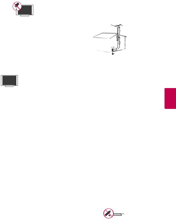
yyANTENNAS Outdoor antenna grounding |
||||||||||||||||||||||||||||||
from the TV, unplug the power cord contact |
||||||||||||||||||||||||||||||
(Can differ by country): |
||||||||||||||||||||||||||||||
an authorized service center. |
|
|
||||||||||||||||||||||||||||
If an outdoor antenna is installed, follow |
|
|
||||||||||||||||||||||||||||
yyDo not press strongly upon the panel with |
||||||||||||||||||||||||||||||
the precautions below. An outdoor antenna |
||||||||||||||||||||||||||||||
system should not be located in the vicinity |
hand or sharp object such as nail, pencil or |
|||||||||||||||||||||||||||||
of overhead power lines or other electric light |
pen, or make a scratch on it. |
|
|
|||||||||||||||||||||||||||
or power circuits, or where it can come in |
yyKeep the product away from direct sunlight. |
|||||||||||||||||||||||||||||
contact with such power lines or circuits as |
|
|
|
|
|
|
|
|
|
|
|
|
|
|
|
|
|
|
|
|||||||||||
death or serious injury can occur. Be sure the |
|
|
|
|
|
|
|
|
|
|
|
|
|
|
|
|
|
|
|
|||||||||||
antenna system is grounded so as to provide |
|
|
|
|
|
|
|
|
|
|
|
|
|
|
|
|
|
|
|
|||||||||||
|
|
|
|
|
|
|
|
|
|
|
|
|
|
|
|
|
|
|
||||||||||||
some protection against voltage surges |
|
|
|
|
|
|
|
|
|
|
|
|
|
|
|
|
|
|
|
|||||||||||
|
|
|
|
|
|
|
|
|
|
|
|
|
|
|
|
|
|
|
||||||||||||
and built-up static charges. Section 810 of |
|
|
|
|
|
|
|
|
|
|
|
|
|
|
|
|
|
|
|
|||||||||||
the National Electrical Code (NEC) in the |
|
|
|
|
|
|
|
|
|
|
|
|
|
|
|
|
|
|
|
|||||||||||
<![endif]>ENGLISH

<![endif]>ENGLISH
6 IMPORTANT SAFETY INSTRUCTIONS
yyDot Defect
The Plasma or LCD panel is a high technology product with resolution of two million to six million pixels. In a very few cases, you could see fine dots on the screen while you’re viewing the TV. Those dots are deactivated pixels and do not affect the performance and reliability of the TV.
yyGenerated Sound
“Cracking” noise: A cracking noise that occurs when watching or turning off the TV is generated by plastic thermal contraction due to temperature and humidity. This noise is common for products where thermal deformation is required.
Electrical circuit humming/panel buzzing: A low level noise is generated from a highspeed switching circuit, which supplies a large amount of current to operate a product. It varies depending on the product.
This generated sound does not affect the performance and reliability of the product.
yyTake care not to touch the ventilation openings. When watching the TV for a long period, the ventilation openings may become hot. This does not affect the performance of the product or cause defects in the product.
yyViewing 3D Imaging (For 3D TV)
-When viewing 3D imaging, watch the TV from an effective viewing angle and within the appropriate distance. If you exceed this viewing angle or distance, you may not be able to view the 3D imaging. Furthermore, the 3D imaging may not display if it is viewed while you are lying down.
-If you watch the 3D imaging too closely or for a long period of time, it may harm your eyesight.
-Watching the TV or playing video games that incorporate 3D imaging with the 3D glasses for a long period of time can cause drowsiness, headaches or fatigue to you and/or your eyes. If you have a headache, or otherwise feel fatigued or drowsy, stop watching the TV and take a rest.
-Pregnant woman, seniors, persons with heart problems or persons who experience frequent drowsiness should refrain from watching 3D TV.
-Some 3D imaging may cause you to duck or dodge the image displayed in the video.
Therefore, it is best if you do not watch 3D TV near fragile objects or near any objects that can be knocked over easily.
-Please prevent children under the age of 5 from watching 3D TV. It may affect their vision development.
-Warning for photosensitization seizure: Some viewers may experience a seizure or epilepsy when exposed to certain factors, including flashing lights or images in TV or video games. If you or anybody from your family has a history of epilepsy or seizure, please consult with your doctor before watching 3D TV.
Also certain symptoms can occur in unspecified conditions without any previous history. If you experience any of the following symptoms, immediately stop watching the 3D imaging and consult a doctor: dizziness or lightheadedness, visual transition or altered vision, visual or facial instability, such as eye or muscle twitching, unconscious action, convulsion, loss of conscience, confusion or disorientation, loss of directional sense, cramps, or nausea. Parents should monitor their children, including teenagers, for these symptoms as they may be more sensitive to the effects of watching 3D TV.
Risk of photosensitization seizure can be reduced with the following actions.
-Take frequent breaks from watching 3D TV.
-For those who have vision that is different in each eye, they should watch the TV after taking vision correction measures.
-Watch the TV so that your eyes are on the same level as the 3D screen and refrain from sitting too closely to the TV.
-Do not watch the 3D imaging when tired or sick, and avoid watching the 3D imaging for a long period of time.
-Do not wear the 3D glasses for any other purpose than viewing 3D imaging on a 3D TV.
-Some viewers may feel disoriented after watching 3D TV. Therefore, after you watch 3D TV, take a moment to regain awareness of your situation before moving.

IMPORTANT SAFETY INSTRUCTIONS 7
LCD
If the TV feels cold to the touch, there may be a small “flicker” when it is turned on. This is normal, there is nothing wrong with TV. Some minute dot defects may be visible on the screen, appearing as tiny red, green, or blue spots. However, they have no adverse effect on the TV’s performance. Avoid touching the LCD screen or holding your finger(s) against it for long periods of time. Doing so may produce some temporary distortion effects on the screen.
DISPOSAL (Hg lamp only used in LCD TVs)
The fluorescent lamp used in this product contains a small amount of mercury. Do not dispose of this product with general household waste. Disposal of this product must be carried out
in accordance to the regulations of your local authority.
<![if ! IE]><![endif]>ENGLISH

<![endif]>ENGLISH
8 TABLE OF CONTENTS
TABLE OF CONTENTS
2 |
LICENSES |
41 |
- Manual Timer Mode |
||
|
|
41 |
- Schedule List Mode |
||
3 |
IMPORTANT SAFETY IN- |
42 |
Using additional options |
||
42 |
- Adjusting aspect ratio |
||||
|
STRUCTIONS |
43 |
- Changing AV modes |
||
|
|
43 |
- Using the input list |
||
8 |
TABLE OF CONTENTS |
44 |
- Locking the buttons on the TV (Child |
||
|
|
Lock) |
|||
|
|
|
|
||
|
|
45 |
Using the quick menu |
||
10 |
ASSEMBLING AND PREPARING |
45 |
Using the customer support |
||
10 |
Unpacking |
45 |
- Testing the Picture / Sound |
||
45 |
- Using the product or service informa- |
||||
13 |
Optional Extras |
||||
|
|
tion |
|||
14 |
Parts and buttons |
|
|
||
45 |
- Using Signal Test |
||||
20 |
Lifting and moving the TV |
||||
|
|
|
|||
20 |
Setting up the TV |
|
46 |
3D IMAGING (FOR 3D TV) |
|
20 |
- Attaching the stand |
||||
26 |
- Mounting on a table |
46 |
3D Technology |
||
|
|
||||
28 |
- Mounting on a wall |
46 |
- When watching 3D imaging |
||
|
|
||||
29 |
- Tidying cables |
47 |
- When using 3D Glasses |
||
|
|
||||
|
|
47 |
- 3D Imaging Viewing Range |
||
30 |
REMOTE CONTROL |
48 |
Viewing 3D Imaging |
||
34 |
WATCHING TV |
50 |
ENTERTAINMENT |
||
|
|
|
|||
34 Connecting to an antenna or cable
34- Connecting an antenna or basic cable
35Connecting to the AC/DC adapter
35Turning the TV on for the first time
36Watching TV
36Managing channels
36- Setting up channels
37- Using favorite channels
38- Checking current program info
40EPG (Electronic Program Guide) (In digital mode)
40- NOW/NEXT Guide Mode
40- D8 Day Guide Mode
41- Date Setting Mode
41 - Detailed Information Box
50- Connecting USB storage devices
51- Browsing files
53 - Viewing Videos
56- DivX registration code
57- Viewing Photos
59 - Listening to music
61 CUSTOMIZING TV SETTINGS
61The Main Menus
62Customizing Settings
62- SETUP Settings
63- PICTURE Settings
67- AUDIO Settings
69- TIME Settings
70- LOCK Settings

TABLE OF CONTENTS 9
71 |
- OPTION Settings |
94 |
EXTERNAL CONTROL DEVICE |
|
|
|
|
|
SETUP |
73 |
MAKING CONNECTIONS |
|
|
|
74 |
Connection Overview |
101 |
OPEN SOURCE LICENSE |
|
75Connecting to a HD receiver, DVD or VCR player
75 - HDMI Connection
75- DVI to HDMI Connection
76- Component Connection
76- Composite Connection
77Connecting to a PC
77 - HDMI Connection
77- DVI to HDMI Connection
78- RGB Connection
79Connecting to an Audio System
79- Digital optical audio connection
79Connecting to a USB
79Connecting to a Headphone ( LCD )
80SIMPLINK Connection
80- Activating and Using the SIMPLINK menus
81MAINTENANCE
81Updating the TV Firmware
82Cleaning Your TV
82- Screen and frame
82- Cabinet and stand
82- Power cord
82Preventing “Image burn” or “Burn-in” on your TV screen
83TROUBLESHOOTING
85 SPECIFICATIONS
92 IR CODES
<![endif]>ENGLISH
10 ASSEMBLING AND PREPARING
ASSEMBLING AND PREPARING
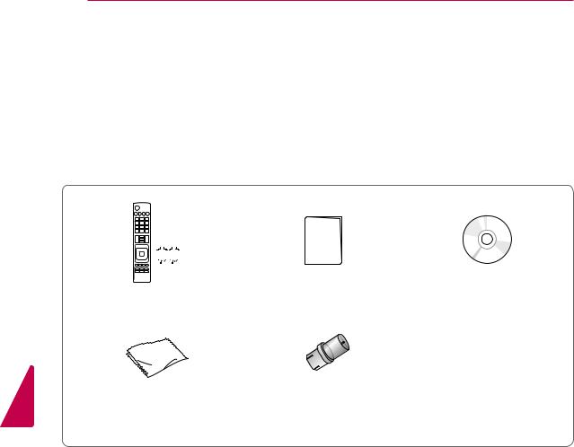
Unpacking
Check your product box for the following items. If there are any missing accessories, contact the local dealer where you purchased your product. The illustrations in this manual may differ from the actual product and item.
<![endif]>ENGLISH
|
|
|
|
|
|
|
|
|
|
|
|
|
|
|
|
|
|
|
|
|
|
|
|
|
|
|
|
|
|
|
|
|
Remote control and batteries (AAA) |
Owner’s manual |
CD manual |
||||||||
Polishing cloth1 |
RF Adapter2 |
(Depending on model) |
(Some models) |
1Gently wipe the spots on the cabinet with the polishing cloth.
2Connect it to the antenna wire after fixing in Antenna Input. This adapter is for supplied in Argentina.
ASSEMBLING AND PREPARING 11
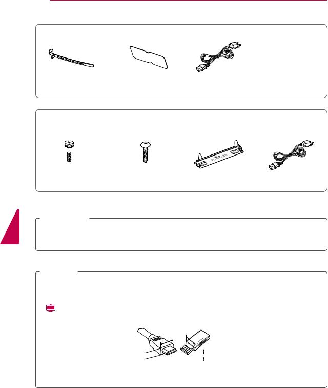
PT250E, PT260E, PW350E, PV550E series |
|
|||
(Other models) |
(For 60PV550E) |
|
||
x 4 |
x 3 |
x 4 |
x 3 |
|
M4 x 26 M5 x 14.5 |
M4 x 28 |
M5 x 24 |
|
|
|
Screw for assembly |
Cable holder |
Power Cord holder |
|
Power Cord |
Protection cover |
Protection cover tape |
|
|
32LV2500, LV3400, LV3500, LV4500, LW4500 series |
|
|
||
(32LV2500) |
(Other models) (Except LV3400 series) |
(For LW4500 series) |
(For 32LV2500, 32LV3400, |
|
32/37LV3500, 32LW4500) |
||||
x 8 |
x 8 |
|
|
|
M4 x 14 |
M4 x 12 |
|
|
|
Screw for assembly |
Composite gender cable |
FPR 3D Glasses1 |
Screw for fixing |
|
Cable holder (Depending on model)
1The number of 3D glasses may differ depending on the model or country.
19/22/26LV2500 series |
|
|
|
||
x 2 |
x 2 |
|
|
|
|
M4 x 16 |
M4 x 6 |
|
|
|
|
Screw for assembly |
Cable holder |
Power Cord |
AC/DC Adapter |
||
(Depending on model) |
|||||
|
|
|
|
||
<![endif]>ENGLISH
12 ASSEMBLING AND PREPARING
22LK330
<![endif]>ENGLISH
Cable holder |
Protection cover |
Power Cord |
LK330, LK450 series
 x 8
x 8
M4 x 20 |
|
|
|
Screw for assembly |
Screw for fixing |
Protection cover |
Power Cord |
 CAUTION
yyDo not use any unapproved items to ensure the safety and product life span.
yyAny damages or injuries by using unapproved items are not covered by the warranty. yyIn case of some model, the thin film on screen is a part of TV, So don’t take it off.
 NOTE
NOTE
yyThe items supplied with your product may vary depending on the model.
yyProduct specifications or contents of this manual may be changed without prior notice due to upgrade of product functions.
yy( LCD ) For an optimal connection, HDMI cables and USB devices should have bezels less than 10 mm (0.39 inches) thick and 18 mm (0.7 inches) width.
A


 A
A
*A  10 mm (0.39 inches) *B
  18 mm (0.7 inches)

ASSEMBLING AND PREPARING 13
Optional Extras
Optional extras can be changed or modified for quality improvement without any notification. Contact your dealer for buying these items.
This device only works with compatible LG Plasma TV, LED LCD TV or LCD TV.
3D Glasses1 |
FPR 3D Glasses2 |
(AG-S230, AG-S250, AG-S270) |
(AG-F2**) |
1Supports for PW350E series
2Supports for LW4500 series
The model name or design may be changed depending on the upgrade of product functions, manufacturer’s circumstances or policies.
<![if ! IE]><![endif]>ENGLISH
<![endif]>ENGLISH
14 ASSEMBLING AND PREPARING
Parts and buttons
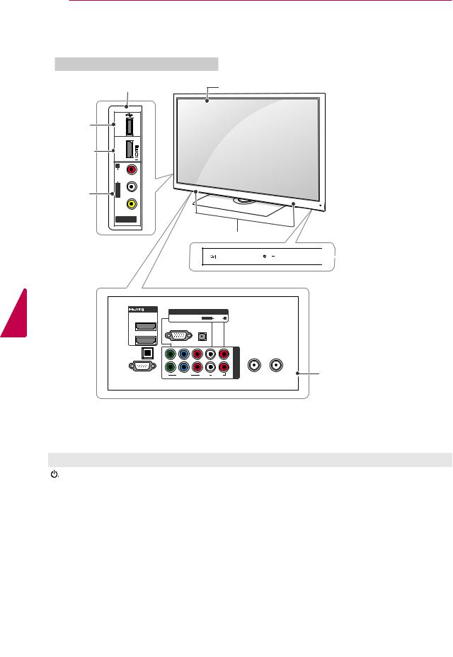
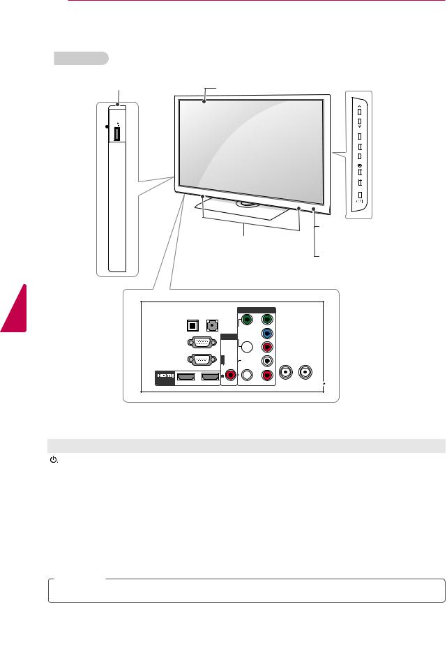
PT250E, PT260E, PW350E, PV550E series
Side Connection panel |
Screen |
|
USB input |
|
|
HDMI input |
|
|
|
<![if ! IE]> <![endif]>AUDIO R |
|
AV (Audio |
|
|
and Video) |
<![if ! IE]> <![endif]>VIDEO |
|
input |
|
|
AV IN 2 |
|
|
|
|
|
|
|
Speakers |
|
|
INPUT HOME ENTER |
|
|
AV IN 1 |
|
|
2 |
|
|
|
|
1 |
|
|
|
|
OPTICAL |
|
|
|
<![if ! IE]> <![endif]>IN |
DIGITAL |
|
|
|
<![if ! IE]> <![endif]>COMPONENT |
AUDIO OUT |
PB |
PR L |
|
|
RS-232C IN |
|
|||
Y |
R |
|
||
(CONTROL&SERVICE) |
|
|
|
|
 Remote control and intelligent1 sensors
VOL 
 CH
CH 
 Touch buttons2
CABLE IN |
Rear Connection panel |
|
(See p.73) |
Touch button2 |
Description |
/ I |
Turns the power on or off. |
|
|
INPUT |
Changes the input source. |
|
|
HOME |
Accesses the main menus, or saves your input and exits the menus. |
|
|
ENTER |
Selects the highlighted menu option or confirms an input. |
|
|
- VOL + |
Adjusts the volume level. |
|
|
v CH ^ |
Scrolls through the saved channels. |
1Intelligent sensor - Adjusts the image quality and brightness based on the surrounding environment.
2All of the buttons are touch sensitive and can be operated through simple touch with your finger.
ASSEMBLING AND PREPARING 15
32LV2500, LV3500, LV4500, LW4500 series
 Screen
|
|
|
Remote control and |
|
|
|
|
intelligent1 sensors |
|
|
|
|
Power indicator |
|
Speakers |
|
|
|
|
CH |
VOL |
ENTER HOME INPUT |
Touch buttons |
2 |
|
||||
|
|
COMPONENT IN |
|
OPTICAL |
(RGB/DVI) |
<![if ! IE]> <![endif]>O |
<![if ! IE]> <![endif]>Y |
DIGITAL |
|
|
|
AUDIO OUT |
AUDIO IN |
<![if ! IE]> <![endif]>VIDE |
<![if ! IE]> <![endif]>BP |
|
AV IN 1 |
||
|
|
|
|
|
<![if ! IE]> <![endif]>O |
|
|
RGB IN(PC) |
<![if ! IE]> <![endif]>VIDE |
|
<![if ! IE]> <![endif]>RP |
|
|
|
|
RS-232C IN(CONTROL&SERVICE) |
<![if ! IE]> <![endif]>AUDI L/MONOO |
<![if ! IE]> <![endif]>AUDI O |
<![if ! IE]> <![endif]>L |
|
|
<![if ! IE]> <![endif]>R |
|
<![if ! IE]> <![endif]>R |
/ DVI IN |
2 |
1 |
2 |
1 |
|
ANTENNA |
CABLE |
IN |
IN |
<![endif]>USB IN
<![endif]>VIDEO / AUDIO IN 3
<![if ! IE]><![endif]>AV IN 2 H/P
 Rear Connection panel (See p.73)
Touch button2 |
Description |
/ I |
Turns the power on or off. |
|
|
INPUT |
Changes the input source. |
|
|
HOME |
Accesses the main menus, or saves your input and exits the menus. |
|
|
ENTER |
Selects the highlighted menu option or confirms an input. |
|
|
- VOL + |
Adjusts the volume level. |
|
|
v CH ^ |
Scrolls through the saved channels. |
1 Intelligent sensor - Adjusts the image quality and brightness based on the surrounding environment.
2All of the buttons are touch sensitive and can be operated through simple touch with your finger.
NOTE
<![endif]>ENGLISH
yyYou can set the power indicator light to on or off by selecting OPTION in the main menus.
16 ASSEMBLING AND PREPARING
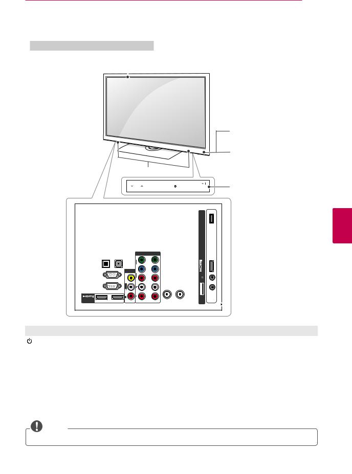
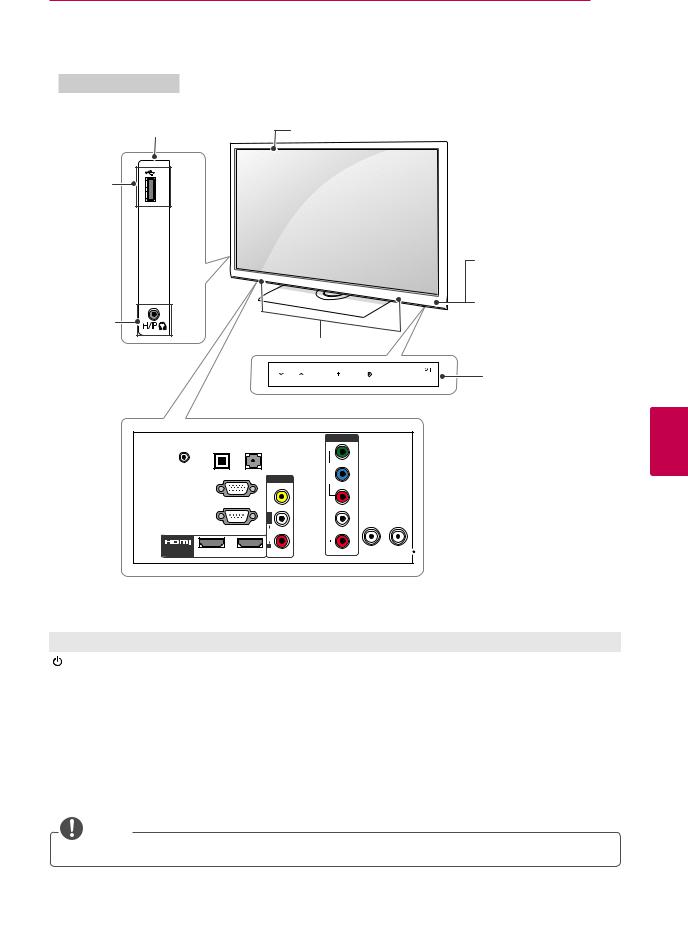
LV3400 series
Side Connection panel Screen
<![if ! IE]><![endif]>INUSB
USB input 

CH
VOL
 Buttons
ENTER
HOME
INPUT
|
Remote control and |
Speakers |
intelligent1 sensors |
|
|
|
Power indicator |
<![endif]>ENGLISH
OPTICAL |
DIGITAL |
AUDIO OUT |
R
2 |
OAV IN
<![if ! IE]><![endif]> VIDE
VIDE
<![endif]> L/MONO
| <![if ! IE]> <![endif]>R |
1 |
<![endif]>R RP BP
2 1
ANTENNA |
CABLE |
IN |
IN |
 Rear Connection panel (See p.73)
Button2 |
Description |
/ I |
Turns the power on or off. |
|
|
INPUT |
Changes the input source. |
|
|
HOME |
Accesses the main menus, or saves your input and exits the menus. |
|
|
ENTER |
Selects the highlighted menu option or confirms an input. |
|
|
- VOL + |
Adjusts the volume level. |
|
|
v CH ^ |
Scrolls through the saved channels. |
1Intelligent sensor - Adjusts the image quality and brightness based on the surrounding environment.
 NOTE
NOTE
yyYou can set the power indicator light to on or off by selecting OPTION in the main menus.
ASSEMBLING AND PREPARING 17
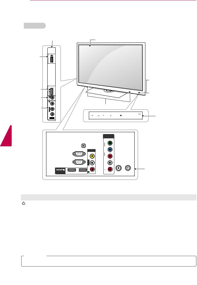
19/22/26LV2500 series |
|
|
|
|
Side Connection panel |
Screen |
|
||
USB input |
<![if ! IE]> <![endif]>IN |
|
|
|
|
<![if ! IE]> <![endif]>USB |
|
|
|
|
|
|
|
Remote control and |
|
|
|
|
intelligent1 sensors |
|
|
|
|
Power indicator |
Headphone |
|
|
|
|
output |
|
|
Speakers |
|
|
|
|
|
|
|
|
CH |
VOL ENTER HOME INPUT |
Touch buttons2 |
DC-IN
/ DVI IN
OPTICAL |
(RGB/DVI) |
|
DIGITAL |
|
|
AUDIO OUT |
AUDIO IN |
|
|
|
OAV IN |
RGB IN (PC) |
<![if ! IE]> <![endif]>VIDE |
|
|
||
|
|
<![if ! IE]> <![endif]>L/MONOO |
RS-232C IN(CONTROL&SERVICE) |
<![if ! IE]> <![endif]>AUDI |
|
|
|
|
|
|
<![if ! IE]> <![endif]>R |
2 |
1 |
|
COMPONENT IN
| <![if ! IE]> <![endif]>O |
<![if ! IE]> <![endif]>Y |
| <![if ! IE]> <![endif]>VIDE |
<![if ! IE]> <![endif]>BP |
|
<![if ! IE]> <![endif]>RP |
| <![if ! IE]> <![endif]>O |
|
| <![if ! IE]> <![endif]>AUDI |
<![if ! IE]> <![endif]>L |
|
|
|
<![if ! IE]> <![endif]>R |
ANTENNA |
CABLE |
IN |
IN |
 Rear Connection panel (See p.73)
Touch button2 |
Description |
/ I |
Turns the power on or off. |
|
|
INPUT |
Changes the input source. |
|
|
HOME |
Accesses the main menus, or saves your input and exits the menus. |
|
|
ENTER |
Selects the highlighted menu option or confirms an input. |
|
|
- VOL + |
Adjusts the volume level. |
|
|
v CH ^ |
Scrolls through the saved channels. |
1 Intelligent sensor - Adjusts the image quality and brightness based on the surrounding environment.
2All of the buttons are touch sensitive and can be operated through simple touch with your finger.
NOTE
<![endif]>ENGLISH
yyYou can set the power indicator light to on or off by selecting OPTION in the main menus.
18 ASSEMBLING AND PREPARING
<![endif]>ENGLISH
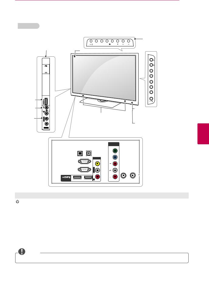
LK450 series
Side Connection panel |
Screen |
|
|
|
||
|
|
|
|
|||
USB input |
|
|
|
|
|
|
| <![if ! IE]> <![endif]>USB |
|
|
|
|
|
|
|
|
|
|
Remote control and |
||
|
|
|
|
intelligent1 sensors |
||
HDMI input |
|
|
|
Power indicator |
|
|
|
|
|
|
|
||
Headphone |
|
|
|
|
|
|
output |
|
|
|
|
|
|
AV (Audio |
|
Speakers |
|
|
|
|
|
|
|
|
|
||
and Video) |
|
|
|
Touch buttons |
2 |
|
input |
CH |
VOL ENTER |
HOME INPUT |
|||
|
||||||
AV IN 2 |
|
|
|
|
|
|
OPTICALDIGITAL |
AUDIO IN |
|||
|
AUDIOOUT |
(RGB/DVI) |
||
|
|
|
|
|
|
|
|
|
|
|
|
|
|
|
|
|
<![if ! IE]> <![endif]>L/MONO |
ANTENNA |
CABLE |
|
|
|
IN |
IN |
R |
) |
|
|
Rear Connection panel |
|
|
|
|
|
2 |
1 |
|
|
(See p.73) |
Touch button2 |
Description |
/ I |
Turns the power on or off. |
|
|
INPUT |
Changes the input source. |
|
|
HOME |
Accesses the main menus, or saves your input and exits the menus. |
|
|
ENTER |
Selects the highlighted menu option or confirms an input. |
|
|
- VOL + |
Adjusts the volume level. |
|
|
v CH ^ |
Scrolls through the saved channels. |
1Intelligent sensor - Adjusts the image quality and brightness based on the surrounding environment.
2All of the buttons are touch sensitive and can be operated through simple touch with your finger.
 NOTE
NOTE
yyYou can set the power indicator light to on or off by selecting OPTION in the main menus.
LK330 series
Side Connection panel
USB input 


HDMI input |
<![if ! IE]> <![endif]>IN 3 |
|
Headphone |
|
|
output |
<![if ! IE]> <![endif]>R |
|
AV (Audio |
<![if ! IE]> <![endif]>AUDIO |
|
| <![if ! IE]> <![endif]>L/MONO |
||
and Video) |
||
| <![if ! IE]> <![endif]>VIDEO |
||
input |
||
AV IN 2 |
ASSEMBLING AND PREPARING 19
(For 22LK330)
|
Buttons |
INPUT HOME ENTER VOL |
CH |
Screen |
(For 26/32LK330) |
|
CH
VOL

 Buttons
ENTER
HOME
INPUT
Remote control
Speakers
Power indicator
|
OPTICALDIGITAL |
AUDIO IN |
|
|
AUDIOOUT |
(RGB/DVI) |
|
|
|
|
AV IN 1 |
|
|
|
<![if ! IE]> <![endif]>O |
|
RGB IN (PC) |
<![if ! IE]> <![endif]>VIDE |
|
|
<![if ! IE]> <![endif]>L/MONO |
||
|
RS-232C IN (CONTROL&SERVICE) |
||
|
<![if ! IE]> <![endif]>AUDI |
||
/ DVI IN |
|
|
|
2 |
1 |
<![if ! IE]> <![endif]>R |
|
COMPONENT
IN
|
<![if ! IE]> <![endif]>Y |
|
| <![if ! IE]> <![endif]>VIDE |
<![if ! IE]> <![endif]>P |
|
|
|
|
|
<![if ! IE]> <![endif]>RP |
|
| <![if ! IE]> <![endif]>O |
<![if ! IE]> <![endif]>L |
ANTENNA |
|
|
|
| <![if ! IE]> <![endif]>AUDI |
|
IN |
| <![if ! IE]> <![endif]>R |
|
CABLE
IN
 Rear Connection panel (See p. 73)
Button2 |
Description |
/ I |
Turns the power on or off. |
|
|
INPUT |
Changes the input source. |
|
|
HOME |
Accesses the main menus, or saves your input and exits the menus. |
|
|
ENTER |
Selects the highlighted menu option or confirms an input. |
|
|
- VOL + |
Adjusts the volume level. |
|
|
v CH ^ |
Scrolls through the saved channels. |
NOTE
<![endif]>ENGLISH
yyYou can set the power indicator light to on or off by selecting OPTION in the main menus.
<![endif]>ENGLISH
20 ASSEMBLING AND PREPARING
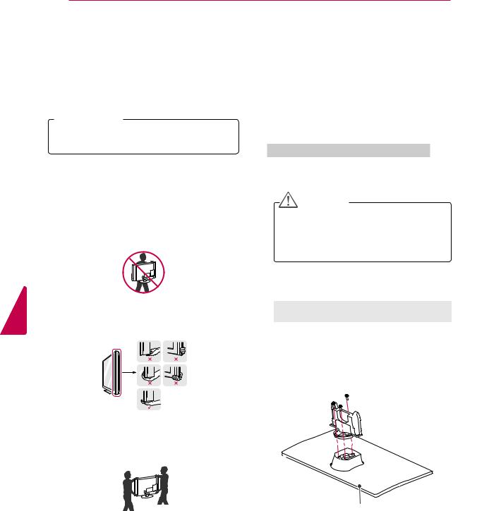
Lifting and moving the TV
When moving or lifting the TV, read the following to prevent the TV from being scratched or damaged and for save transportation regardless of its type and size.
 CAUTION
yyAvoid touching the screen at all times, as this may result in damage to the screen.
yyIt is recommended to move the TV in the box or packing material that the TV originally came in.
yyBefore moving or lifting the TV, disconnect the power cord and all cables.
yyWhen holding the TV, the screen should face away from you to prevent the screen from scratches.
yyHold the top and bottom of the TV frame firmly. Make sure not to hold the transparent part, speaker, or speaker grill area.
yyWhen transporting a large TV, there should be at least 2 people.
yyWhen transporting the TV by hand, hold the TV as shown in the following illustration.
yyWhen transporting the TV, do not expose the TV to jolts or excessive vibration.
yyWhen transporting the TV, keep the TV upright, never turn the TV on its side or tilt towards the left or right.
Setting up the TV
Put your TV on a pedestal stand and mount the TV on a table or wall.
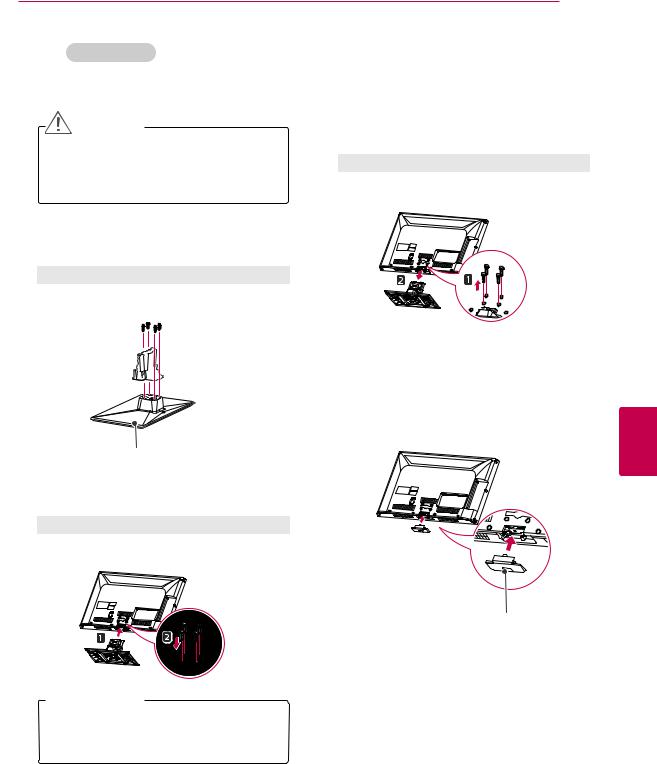
Attaching the stand
If you are not mounting the TV to a wall, use the following instructions to attach the stand.
PT250E, PT260E, PW350E, PV550E series
1Lay the TV with the screen side down on a flat surface.
CAUTION
yyLay a foam mat or soft protective cloth on the surface to protect the screen from damage. Make sure no objects press against the screen.
2Assemble the parts of the STAND BODY with the STAND BASE of the TV.
Model |
Screw for |
Number of |
|
assembly |
screws |
|
|
|
42/50PT250E |
M5 x 14.5 |
3 |
42/50PT260E |
|
|
42/50PW350E |
|
|
50PV550E |
|
|
60PV550E |
M5 x 24 |
3 |

 Stand Body
Stand Base
|
|
|
ASSEMBLING AND PREPARING 21 |
|||
3 Secure the TV and the stand with the 4 |
To detach the stand, |
|
||||
screws. |
|
|
1 Lay the TV with the screen side down on a flat |
|||
|
|
|
||||
Model |
Screw for |
Number of |
surface. |
|
|
|
|
|
|
||||
|
assembly |
screws |
2 Remove the 4 screws and pull the stand away |
|||
42/50PT250E |
M4 x 26 |
4 |
||||
from the TV. |
|
|
||||
42/50PT260E |
|
|
|
|
||
42/50PW350E |
|
|
|
|
|
|
50PV550E |
|
|
Model |
Screw for |
Number of |
|
60PV550E |
M4 x 28 |
4 |
|
assembly |
screws |
|
|
|
|
42/50PT250E |
M4 x 26 |
4 |
|
|
|
|
42/50PT260E |
|
|
|
|
|
|
42/50PW350E |
|
|
|
|
|
|
50PV550E |
|
|
|
|
|
|
60PV550E |
M4 x 28 |
4 |
|
 CAUTION
yyTighten the screws firmly to prevent the TV from tilting forward. Do not over tighten.
3Push the supplied protection cover into the opening at the bottom of the TV until it locks in place. Attach the protection cover tape. Attach the protection cover tape.
-This will protect the opening from accumulating dust and dirt.
-When installing the wall mounting bracket, use the Protection cover.
Protection |
cover tape |
Protection cover
<![endif]>ENGLISH
<![endif]>ENGLISH
22 ASSEMBLING AND PREPARING
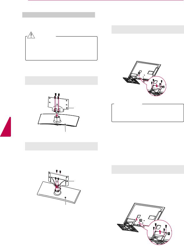
32LV2500, LV3400, LV3500, LV4500, LW4500 series
1Lay the TV with the screen side down on a flat surface.
CAUTION
yyLay a foam mat or soft protective cloth on the surface to protect the screen from damage. Make sure no objects press against the screen.
2Assemble the parts of the STAND BODY with the STAND BASE of the TV.
Model |
Screw for |
Number of |
|
assembly |
screws |
32LV2500 |
M4 x 14 |
4 |
3Secure the TV and the stand with the 4 screws.
Model |
Screw for |
Number of |
|
assembly |
screws |
32LV2500 |
M4 x 14 |
4 |
LV3400 |
M4 x 12 |
4 |
LV3500 |
|
|
LV4500 |
|
|
LW4500 series |
|
|
Stand Body |
Stand Base
Model |
Screw for |
Number of |
|
assembly |
screws |
|
|
|
LV3400 |
M4 x 12 |
4 |
LV3500 |
|
|
LV4500 |
|
|
LW4500 series |
|
|
Stand Body |
 CAUTION
yyTighten the screws firmly to prevent the TV from tilting forward. Do not over tighten.
To detach the stand,
1Lay the TV with the screen side down on a flat surface.
2Remove the 4 screws and pull the stand away from the TV.
Model |
Screw for |
Number of |
|
assembly |
screws |
32LV2500 |
M4 x 14 |
4 |
LV3400 |
M4 x 12 |
4 |
LV3500 |
|
|
LV4500 |
|
|
LW4500 series |
|
|
Stand Base
ASSEMBLING AND PREPARING 23
|
19/22/26LV2500 series |
To detach the stand, |
1Lay the TV with the screen side down on a flat surface.
CAUTION
yyLay a foam mat or soft protective cloth on the surface to protect the screen from damage. Make sure no objects press against the screen.
2Assemble the parts of the STAND BODY with the STAND BASE of the TV.
Screw for assembly |
Number of screws |
M4 x 6 |
2 |
Stand Body
Stand Base
3Secure the TV and the stand with the 2 screws.
Screw for assembly |
Number of screws |
|
|
M4 x 16 |
2 |
1Lay the TV with the screen side down on a flat surface.
2Remove the 2 screws and pull the stand away from the TV.
Screw for assembly |
Number of screws |
|
|
M4 x 16 |
2 |
|
|
 CAUTION
<![endif]>ENGLISH
yyTighten the screws firmly to prevent the TV from tilting forward. Do not over tighten.
24 ASSEMBLING AND PREPARING
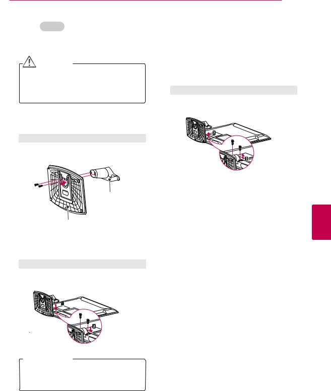
22LK330
1Lay the TV with the screen side down on a flat surface.
CAUTION
yyLay a foam mat or soft protective cloth on the surface to protect the screen from damage. Make sure no objects press against the screen.
2 Assemble
To detach the stand,
1Lay the TV with the screen side down on a flat surface.
2Remove the screws and pull the stand away from the TV.
3 Push the supplied protection cover into the opening at the bottom of the TV until it locks in place.
This will protect the opening from accumulating dust and dirt.
When installing the wall mounting bracket, use the Protection cover.
<![if ! IE]><![endif]>ENGLISH
ASSEMBLING AND PREPARING 25
|
26/32LK330, LK450 series |
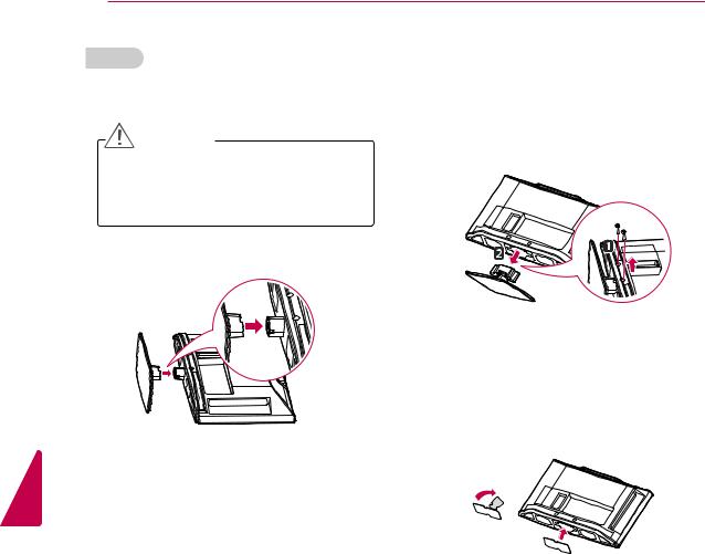
To detach the stand, |
1Lay the TV with the screen side down on a flat surface.
CAUTION
yyLay a foam mat or soft protective cloth on the surface to protect the screen from damage. Make sure no objects press against the screen.
2Assemble the parts of the STAND BODY with the STAND BASE of the TV.
Screw for assembly |
Number of screws |
M4 x 20 |
4 |
1Lay the TV with the screen side down on a flat surface.
2Remove the 4 screws and pull the stand away from the TV.
Screw for assembly |
Number of screws |
|
|
|
|
|
|
M4 x 20 |
4 |
|
|
|
|
|
|
|
|
|
|
Stand Body 


Stand Base
3Secure the TV and the stand with the 4 screws.
Screw for assembly |
Number of screws |
M4 x 20 |
4 |
3Push the supplied protection cover into the opening at the bottom of the TV until it locks in place.
This will protect the opening from accumulating dust and dirt.
When installing the wall mounting bracket, use the Protection cover.
Protection cover
 CAUTION
<![endif]>ENGLISH
yyTighten the screws firmly to prevent the TV from tilting forward. Do not over tighten.
<![endif]>ENGLISH
26 ASSEMBLING AND PREPARING
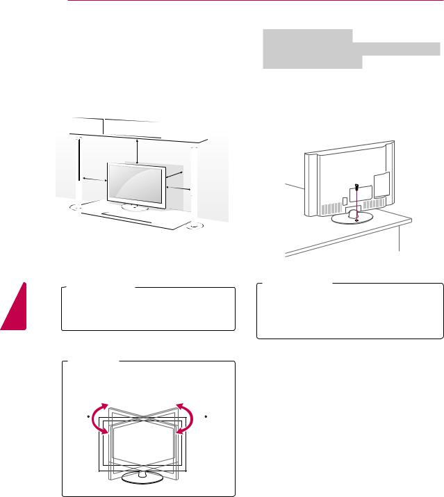
Mounting on a table
1Lift and tilt the TV into its upright position on a table.
-Leave a 10 cm (minimum) space from the wall for proper ventilation.
|
10 cm |
|
10 cm |
10 |
cm |
|
||
|
|
|
|
10 cm |
|
2 Connect the power cord to a wall outlet.
 CAUTION
yyDo not place the TV near or on sources of heat, as this may result in fire or other damage.
 NOTE
NOTE
yySwivel 20 degrees to the left or right and adjust the angle of the TV to suit your view.
20 |
20 |
Securing the TV to a table
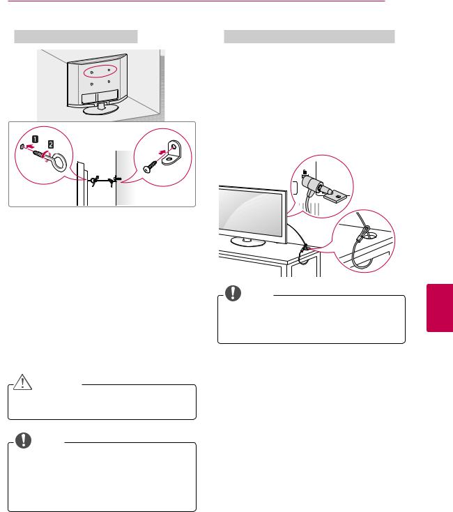
(For 26/32LK330, 32/37/42LK450, 32LV2500, 32LV3400, 32/37LV3500)
Fix the TV to a table to prevent from tilting forward, damage, and potential injury. Mount the TV on a table, and then insert and tighten the supplied screw on the rear of the stand.
 WARNING
yyTo prevent TV from falling over, the TV should be securely attached to the floor/wall per installation instructions. Tipping, shaking, or rocking the TV may cause injury.
ASSEMBLING AND PREPARING 27
Securing the TV to a wall (optional)
1Insert and tighten the eye-bolts, or TV brackets and bolts on the back of the TV.
-If there are bolts inserted at the eye-bolts position, remove the bolts first.
2Mount the wall brackets with the bolts to the wall.
Match the location of the wall bracket and the eye-bolts on the rear of the TV.
3Connect the eye-bolts and wall brackets tightly with a sturdy rope.
Make sure to keep the rope horizontal with the flat surface.
CAUTION
Using the Kensington security system (optional)
The Kensington security system connector is located at the rear of the TV. For more information of installation and using, refer to the manual provided with the Kensington security system or visit http://www.kensington.com.
Connect the Kensington security system cable between the TV
NOTE
yyThe Kensington security system is optional. You can obtain additional accessories from your local dealer.
yyMake sure that children do not climb on or hang on the TV.
NOTE
yyUse a platform or cabinet that is strong and large enough to support the TV securely. yyBrackets, bolts and ropes are optional. You can obtain additional accessories from your
local dealer.
<![endif]>ENGLISH

28 ASSEMBLING AND PREPARING
Mounting on a wall
Attach an optional wall mount bracket at the rear of the TV carefully and install the wall mount bracket on a solid wall perpendicular to the floor. When you attach the TV to other building materials, please contact qualified personnel. We recommend that you use an LG brand wall mount when mounting the TV to a wall.
10 cm
10 cm  10 cm
10 cm
10 cm
| <![if ! IE]> <![endif]>ENGLISH |
Make sure to use screws and wall mounts that |
|||
meet the VESA standard. Standard dimensions for |
||||
|
||||
|
the wall mount kits are described in the following |
|||
|
table. |
|
|
|
|
|
|
|
|
|
Model |
42/50PT250E |
60PV550E |
|
|
|
42/50PT260E |
|
|
|
|
42/50PW350E |
|
|
|
|
50PV550E |
|
|
|
VESA |
400 x 400 |
600 x 400 |
|
|
Standard screw |
M6 |
M8 |
|
|
Number of screws |
4 |
4 |
|
|
Wall mount bracket |
PSW400B, |
PSW600B |
|
|
(optional) |
PSW400BG |
|
|
|
|
|
|
|
Model |
19/22/26LV2500 |
32LK330 |
|
22/26LK330 |
32LK450 |
|
|
32LV2500 |
|
|
32LV3400 |
|
|
32LV3500 |
|
|
32LW4500 |
VESA |
100 x 100 |
200 x 100 |
Standard screw |
M4 |
M4 |
Number of screws |
4 |
4 |
Wall mount bracket LSW100B, |
LSW100B, |
|
(optional) |
LSW100BG |
LSW100BG |
Model |
37LV3500 |
42/47LV3500 |
|
37/42LK450 |
42/47LV4500 |
|
|
42/47LW4500 |
VESA |
200 x 200 |
400 x 400 |
Standard screw |
M6 |
M6 |
Number of screws |
4 |
4 |
Wall mount bracket |
LSW200B, |
LSW400B, |
(optional) |
LSW200BG |
LSW400BG |
|
|
|
Model |
42LV3400 |
|
|
VESA |
400 x 400 |
Standard screw |
M6 |
Number of screws 4
Wall mount bracket LSW400BX, (optional) LSW400BXG
 CAUTION
yyDisconnect the power first, and then move or install the TV. Otherwise electric shock may occur.
yyIf you install the TV on a ceiling or slanted wall, it may fall and result in severe injury. Use an authorized LG wall mount and contact the local dealer or qualified personnel.
yyDo not over tighten the screws as this may cause damage to the TV and void your warranty.
yyUse the screws and wall mounts that meet the VESA standard. Any damages or injuries by misuse or using an improper accessory are not covered by the warranty.
 NOTE
NOTE
yyUse the screws that are listed on the VESA standard screw specifications.
yyThe wall mount kit includes an installation manual and necessary parts.
yyThe wall mount bracket is optional. You can obtain additional accessories from your local dealer.
yyThe length of screws may differ depending on the wall mount. Make sure to use the proper length.
yyFor more information, refer to the manual supplied with the wall mount.
ASSEMBLING AND PREPARING 29
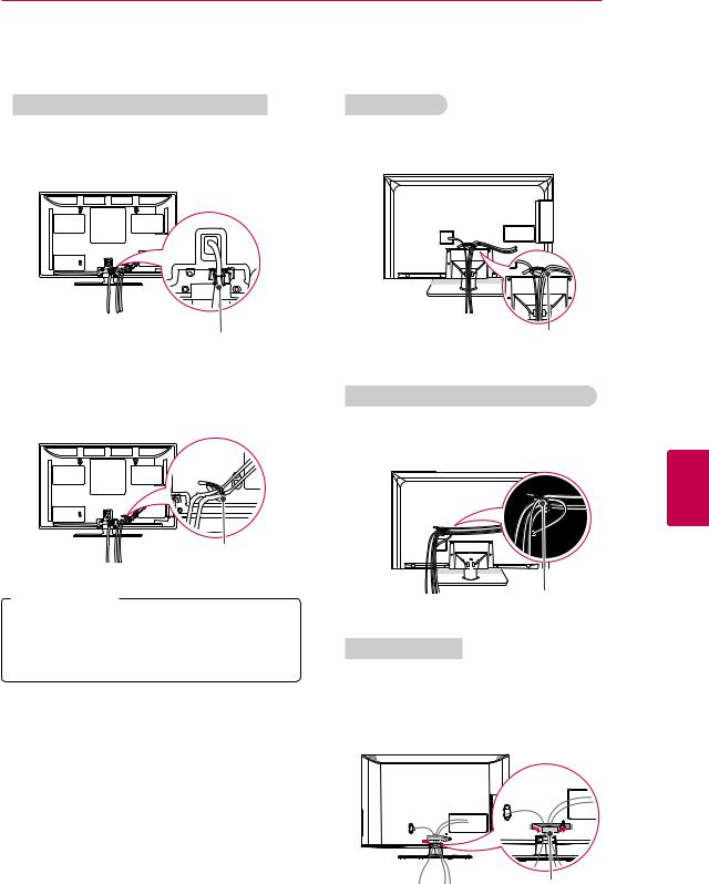
Tidying cables
PT250E, PT260E, PW350E, PV550E series |
19/22/26LV2500 |
1Install the power cord holder and power cord. It will help prevent the power cable from being removed by
1Gather and bind the cables with the cable holder.
Power cord holder
2Gather and bind the cables with the cable holder.
Cable holder
 CAUTION
yyDo not move the TV by holding the cable holder and power cord holder, as the cable holders may break, and injuries and damage to the TV may occur.
Cable holder
32LV2500, LV3400, LV3500, LV4500, LW4500 series
1Gather and bind the cables with the cable holder on the TV back cover.
<![if ! IE]><![endif]>ENGLISH
Cable holder
LK330, LK450 series
1Gather and bind the cables with the cable management clip.
2Fix the cable management clip firmly to the TV.
Cable management clip
<![endif]>ENGLISH
30 REMOTE CONTROL
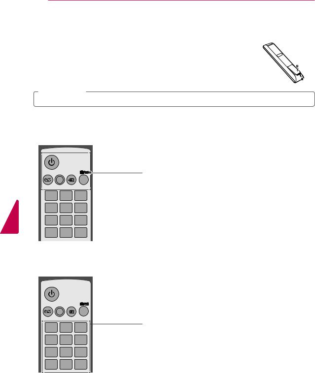
REMOTE CONTROL
The descriptions in this manual are based on the buttons on the remote control. Please read this manual carefully and use the TV correctly.
To replace batteries, open the battery cover, replace batteries (1.5 V AAA) matching the  and
and  ends to the label inside the compartment, and close the battery cover. To remove the batteries, perform the installation actions in reverse.
 CAUTION
yyDo not mix old and new batteries, as this may damage the remote control.
Make sure to point the remote control toward at the remote control sensor on the TV.
ENERGY AV MODE INPUT
TV/ RAD
SAVING
1 2 3
4 5 6
7 8 9
LIST 0 Q.VIEW
ENERGY AV MODE INPUT
TV/ RAD
SAVING
1 2 3 
4 5 6
7 8 9
 (POWER)
Turns the TV on or off.
ENERGY SAVING (See p.63)
Adjusts the Energy Saving settings.
AV MODE (See p.43)
Selects an AV mode.
INPUT (See p.43)
Rotates through inputs.
Also switches the TV on from standby.
TV/RAD
Selects Radio, TV, CATV and DTV channel.
Number buttons
Enters numbers.
LIST (See p.37)
Accesses the saved channel list.
Q.VIEW
Alternates between the two last channels selected (pressing repeatedly).
LIST 0 Q.VIEW
Loading...