


 Loading...
OWNER’S MANUAL
LED LCD TV
Please read this manual carefully before operating your set and retain it for future reference.
LED LCD TV MODELS |
LCD TV MODELS |
22LQ630H |
42CQ610H |
26LQ630H |
|
32LQ630H |
|
P/NO : SAC34026011 (1210-REV02) |
www.lg.com |
WARNING / CAUTION
WARNING/CAUTION
RISKOFELECTRICSHOCK
DO NOT OPEN
TO REDUCE THE RISK OF ELECTRIC SHOCK DO NOT REMOVE COVER (OR BACK). NO USER SERVICEABLE PARTS INSIDE.
REFER TO QUALIFIED SERVICE PERSONNEL.
The lightning flash with arrowhead symbol, within an equilateral triangle, is
intended to alert the user to the presence of uninsulated “dangerous voltage” within the product’s enclosure that may be of sufficient magnitude to constitute a risk of electric shock to persons.
The exclamation point within an equilateral triangle is intended to alert
the user to the presence of important operating and maintenance (servicing) instructions in the literature accompanying the appliance.
WARNING/CAUTION
TO REDUCE THE RISK OF FIRE AND ELECTRIC SHOCK, DO NOT EXPOSE THIS PRODUCT TO RAIN OR MOISTURE.
WARNING / CAUTION
To prevent fire or shock hazards, do not expose this product to rain or moisture.
FCC NOTICE
Class B digital device
This equipment has been tested and found to comply with the limits for a Class B digital device, pursuant to Part 15 of the FCC Rules. These limits are designed to provide reasonable protection against harmful interference in a residential installation. This equipment generates, uses and can radiate radio frequency energy and, if not installed and used in accordance with the instructions, may cause harmful interference to radio communications. However, there is no guarantee that interference will not occur in a particular installation. If this equipment does cause harmful interference to radio or television reception, which can be determined by turning the equipment off and on, the user is encouraged to try to correct the interference by one or more of the following measures:
-Reorient or relocate the receiving antenna.
-Increase the separation between the equipment and receiver.
-Connect the equipment to an outlet on a circuit different from that to which the receiver is connected.
-Consult the dealer or an experienced radio/TV technician for help.
Any changes or modifications expressly approved by the party responsible for compliance could void the user’s authority to operate the equipment.
NOTE TO CABLE/TV INSTALLER CAUTION
This reminder is provided to call the CATV system installer’s attention to Article 820-40 of the National Electric Code (U.S.A.). The code provides guidelines for proper grounding and, in particular, specifies that the cable ground shall be connected to the grounding system of the building, as close to the point of the cable entry as practical.
Do not attempt to modify this product in any way without written authorization from LG Electronics. Unauthorized modification could void the user’s authority to operate this product
2
SAFETY INSTRUCTIONS
IMPORTANT SAFETY INSTRUCTIONS
Read these instructions.
Keep these instructions.
Heed all warnings.
Follow all instructions.
1 |
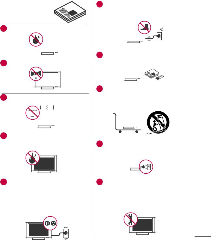
Do not use this apparatus near water. |
||||||
|
|
|
|
|
|
|
|
|
|
|
|
|
|
|
|
|
|
|
|
|
|
|
|
|
|
|
|
|
|
|
|
|
|
|
|
|
|
|
|
2 |
Clean only with a dry cloth. |
|
|
|
|
|
|
|
6 Protect the power cord from being walked on or pinched particularly at plugs, convenience receptacles, and the point where they exit from the apparatus.
|
|
|
|
|
|
|
|
|
|
|
|
|
|
|
|
|
|
|
|
|
|
|
|
|
|
|
|
|
|
|
|
|
|
|
|
|
|
|
|
|
|
|
|
|
|
|
|
|
|
|
|
|
|
|
|
|
|
|
|
|
|
|
|
|
|
|
|
|
|
|
|
|
|
|
|
|
|
|
|
|
|
|
|
|
|
|
|
|
|
|
7 |
Only use attachments/accessories specified by |
|||||||||||
|
the manufacturer. |
|||||||||||
|
|
|
|
|
|
|
|
|
|
|
|
|
|
|
|
|
|
|
|
|
|
|
|
|
|
|
|
|
|
|
|
|
|
|
|
|
|
|
|
|
|
|
|
|
|
|
|
|
|
|
|
|
|
|
|
|
|
|
|
|
|
|
|
|
3 |
Do not block any ventilation openings. Install in |
|||||||||
|
accordance with the manufacturer’s instructions. |
|||||||||
|
|
|
|
|
|
|
|
|
|
|
|
|
|
|
|
|
|
|
|
|
|
|
|
|
|
|
|
|
|
|
|
|
|
|
|
|
|
|
|
|
|
|
|
|
|
|
|
|
|
|
|
|
|
|
|
|
|
|
|
|
|
|
|
|
|
4 Do not install near any heat sources such as radiators, heat registers, stoves, or other apparatus (including amplifiers)that produce heat.
8 Use only with the cart, stand, tripod, bracket, or table specified by the manufacturer, or sold with the apparatus. When a cart is used, use caution when moving the cart/apparatus combination to avoid injury from tip-over.
|
|
|
|
|
|
|
|
|
|
|
|
|
|
|
|
|
|
|
|
|
|
|
|
|
|
|
|
|
|
|
|
|
|
|
|
|
|
|
|
|
|
|
|
|
|
|
|
|
|
|
|
|
|
|
|
|
|
|
|
|
|
|
|
|
|
|
|
|
|
|
|
|
|
|
|
|
|
|
|
9 |
Unplug this apparatus during lighting storms or |
||||||||||||||
|
when unused for long periods of time. |
||||||||||||||
|
|
|
|
|
|
|
|
|
|
|
|
|
|
|
|
|
|
|
|
|
|
|
|
|
|
|
|
|
|
|
|
|
|
|
|
|
|
|
|
|
|
|
|
|
|
|
|
|
|
|
|
|
|
|
|
|
|
|
|
|
|
|
|
5 Do not defeat the safety purpose of the polarized or grounding-type plug. A polarized plug has two blades with one wider than the other. A grounding type plug has two blades and a third grounding prong, The wide blade or the third prong are provided for your safety. If the provided plug does not fit into your outlet, consult an electrician for replacement of the obsolete outlet.
10Refer all servicing to qualified service personnel. Servicing is required when the apparatus has been damaged in any way, such as power-supply cord or plug is damaged, liquid has been spilled or objects have fallen into the apparatus, the apparatus has been exposed to rain or moisture, does not operate normally, or has been dropped.
3

11Never touch this apparatus or antenna during a thunder or lighting storm.
12When mounting a TV on the wall, make sure not to install the TV by the hanging power and signal cables on the back of the TV.
13Do not allow an impact shock or any objects to fall into the product, and do not drop onto the screen.
14Keep the packing anti-moisture material or vinyl packing out of the reach of children. Antimoisture material is harmful if swallowed. If swallowed by mistake, force the patient to vomit and visit the nearest hospital. Additionally, vinyl packing can cause suffocation. Keep it out of the reach of children.
15CAUTION concerning the Power Cord :
It is recommend that appliances be placed upon a dedicated circuit; that is, a single outlet circuit which powers only that appliance and has no additional outlets or branch circuits. Check the specification page of this owner's manual to be certain.
Do not connect too many appliances to the same AC power outlet as this could result in fire or electric shock.
Do not overload wall outlets. Overloaded wall outlets, loose or damaged wall outlets, extension cords, frayed power cords, or damaged or cracked wire insulation are dangerous. Any of these conditions could result in electric shock or fire. Periodically examine the cord of your appliance, and if its appearance indicates damage or deterioration, unplug it, discontinue use of the appliance, and have the cord replaced with an exact replacement part by an authorized servicer. Protect the power cord from physical or mechanical abuse, such as being twisted, kinked, pinched, closed in a door, or walked upon. Pay particular attention to plugs, wall outlets, and the point where the cord exits the appliance.
Do not move the TV with the power cord plugged in. Do not use a damaged or loose power cord. Be sure do grasp the plug when unplugging the power cord. Do not pull on the power cord to unplug the TV.
16Do not stick metal objects or any other conductive material into the power cord. Do not touch the end of the power cord while it is plugged in.
17WARNING - To reduce the risk of fire or electrical shock, do not expose this product to rain, moisture or other liquids. Do not touch
the TV with wet hands. Do not install this product near flammable objects such as gasoline or candles or expose the TV to direct air conditioning.
18Do not expose to dripping or splashing and do not place objects filled with liquids, such as vases, cups, etc. on or over the apparatus (e.g. on shelves above the unit).
19GROUNDING
(Except for devices which are not grounded.) Ensure that you connect the earth ground wire to prevent possible electric shock. (i.e. a TV with a three-prong grounded AC plug must be connected to a three-prong grouned AC outlet) If grounding methods are not possible, have a qualified electrician install a separate circuit breaker.
Do not try to ground the unit by connecting it to telephone wires, lightening rods, or gas pipes.
Power
Short-circuit Supply
Breaker
20DISCONNECTING DEVICE FROM MAINS
Mains plug is the disconnecting device. The plug must remain readily operable.
21As long as this unit is connected to the AC wall outlet, it is not disconnected from the AC power source even if you turn off this unit by SWITCH.
Do not attempt to modify this product in any way without written authorization from LG Electronics. Unauthorized modification could void the user’s authority to operate this product.
22ANTENNAS
Outdoor antenna grounding
If an outdoor antenna is installed, follow the precautions below. An outdoor antenna system should not be located in the vicinity of overhead power lines or other electric light or power circuits, or where it can come in contact with such power lines or circuits as death or serious injury can occur.
Be sure the antenna system is grounded so as
4

to provide some protection against voltage surges and built-up static charges.
Section 810 of the National Electrical Code (NEC) in the U.S.A. provides information with respect to proper grounding of the mast and supporting structure, grounding of the lead-in wire to an antenna discharge unit, size of grounding conductors, location of antenna discharge unit, connection to grounding electrodes and requirements for the grounding electrode.
Antenna grounding according to the National Electrical Code, ANSI/NFPA 70
Ground Clamp |
|
Antenna Lead in Wire |
|
|
|
|
|
Antenna Discharge Unit |
|
|
(NEC Section 810-20) |
|
|
Grounding Conductor |
Electric Service |
|
(NEC Section 810-21) |
|
|
|
Equipment |
|
Ground Clamps |
|
|
|
|
|
Power Service Grounding |
|
|
Electrode System (NEC |
|
|
Art 250, Part H) |
NEC: National Electrical Code
23Cleaning
When cleaning, unplug the power cord and scrub gently with a soft cloth to prevent scratching. Do not spray water or other liquids directly on the TV as electric shock may occur. Do not clean with chemicals such as alcohol, thinners or benzene.
24Moving
Make sure the product is turned off, unplugged and all cables have been removed. It may take 2 or more people to carry larger TVs. Do not press against or put stress on the front panel of the TV.
25Ventilation
Install your TV where there is proper ventilation. Do not install in a confined space such as a bookcase. Do not cover the product with cloth or other materials (e.g.) plastic while plugged in. Do not install in excessively dusty places.
26If you smell smoke or other odors coming from the TV, unplug the power cord contact and authorized service center.
27Do not press strongly upon the panel with a hand or sharp object such as nail, pencil or pen, or make a scratch on it.
28Keep the product away from direct sunlight.
29Dot Defect
The Plasma or LCD panel is a high technology product with resolution of two million to six million pixels. In a very few cases, you could see fine dots on the screen while you’re viewing the TV. Those dots are deactivated pixels and do not affect the performance and reliability of the TV.
30Generated Sound
“Cracking” noise: A cracking noise that occurs when watching or turning off the TV is generated by plastic thermal contraction due to temperature and humidity. This noise is common for products where thermal deformation is required.
Electrical circuit humming/panel buzzing: A low level noise is generated from a high-speed switching circuit, which supplies a large amount of current to operate a product. It varies depending on the product.
This generated sound does not affect the performance and reliability of the product.
31Take care not to touch the ventilation openings. When watching the TV for a long period, the ventilation openings may become hot.
32If the TV feels cold to the touch, there may be a small “flicker” when it is turned on. This is normal, there is nothing wrong with TV.
Some minute dot defects may be visible on the screen, appearing as tiny red, green, or blue spots. However, they have no adverse effect on the monitor's performance.
Avoid touching the LCD screen or holding your finger(s) against it for long periods of time. Doing so may produce some temporary distortion effects on the screen.
ON DISPOSAL
(Only Hg lamp used LCD TV)
The fluorescent lamp used in this product contains a small amount of mercury. Do not dispose of this product with general household waste. Disposal of this product must be carried out in accordance to the regulations of your local authority.
5

CONTENTS
WARNING / CAUTION . . . . . . . 2 SAFETY INSTRUCTIONS . . . . . . 3
CONTENTS . . . . . . . . . . . . . . 6
FEATURES OF THIS TV . . . . . . . 7
PREPARATION
Accessories . . . . . . . . . . . . . . . . 8 Protection Cover . . . . . . . . . . . . . 9 Front Panel Information . . . . . . . . . . 10 Back Panel Information . . . . . . . . . . 12 Cable Management . . . . . . . . . . . . 15 Wall Mount Installation . . . . . . . . . . 17 Kensington Security System . . . . . . . . 17 VESA Wall Mounting . . . . . . . . . . . 18 Antenna or Cable Connection . . . . . . . 19
EXTERNAL EQUIPMENT SETUP
HD Receiver Setup . . . . . . . . . . . . 20 DVD Setup . . . . . . . . . . . . . . . 22 VCR Setup . . . . . . . . . . . . . . . 23 Other A/V Source Setup . . . . . . . . . 25 Pillow Speaker Setup . . . . . . . . . . . 26 PC Setup . . . . . . . . . . . . . . . . 27
WATCHING TV / CHANNEL CONTROL
Turning On TV . . . . . . . . . . . . . . 33 Channel Selection . . . . . . . . . . . . 33 Volume Adjustment . . . . . . . . . . . . 33 Initial Setting . . . . . . . . . . . . . . 34 On-Screen Menus Selection . . . . . . . . 36 Channel Setup
- Auto Scan (Auto Tuning) . . . . . . . 37
-Add / Delete Channel (Manual Tuning) . 38
-Channel Editing . . . . . . . . . . . 39 Channel Label . . . . . . . . . . . . . . 40 Input List . . . . . . . . . . . . . . . . 41
PICTURE CONTROL
Picture Size (Aspect Ratio) Control . . . . |
. 42 |
Preset Picture Settings . . . . . . . . . . |
44 |
Manual Picture Adjustment - User Mode . . . 45 |
|
Picture Improvement Technology . . . . . |
. 46 |
Picture Reset . . . . . . . . . . . . . . |
48 |
Demo Mode . . . . . . . . . . . . . . |
49 |
SOUND & LANGUAGE CONTROL
Auto Volume Leveler (Auto Volume) . . . . |
50 |
Clear Voice II . . . . . . . . . . . . . . |
51 |
Balance . . . . . . . . . . . . . . . . . 52 |
|
Preset Sound Settings (Sound Mode) . . . |
. 53 |
Sound Setting Adjustment - User Mode . . |
. 54 |
Infinite Sound . . . . . . . . . . . . . . |
55 |
TV Speakers On/Off Setup . . . . . . . . |
56 |
Audio Reset . . . . . . . . . . . . . . . 57 |
|
Stereo/SAP Broadcast Setup . . . . . . . |
. 58 |
Audio Language . . . . . . . . . . . . . |
59 |
On-Screen Menus Language Selection . . . |
. 60 |
Caption Mode |
|
- Analog Broadcasting System Captions . |
61 |
- Digital Broadcasting System Captions . . 62 |
|
- Caption Option . . . . . . . . . . |
. 63 |
TIME SETTING
Clock Setting
- Auto Clock Setup . . . |
. . . . . . . |
. . . . . . . . . . 64 |
- Manual Clock Setup |
. . . . |
. . . . . 65 |
Auto On/Off Time Setting |
. . . . . . . . 66 |
|
Sleep Timer Setting . . . . . . . . . . . . 67 |
||
Auto Shut-Off Setting . . |
. . . |
. . . . . 67 |
PARENTAL CONTROL / RATINGS
Set Password & Lock System . . . . . . . . 68 Channel Blocking . . . . . . . . . . . . . 71 Movie & TV Rating . . . . . . . . . . . . 72 Downloadable Rating . . . . . . . . . . . 75 External Input Blocking . . . . . . . . . . 76
USB
Entry Modes . . . . . . . . . . . . . . . 77 Movie List . . . . . . . . . . . . . . . . 79 Photo List . . . . . . . . . . . . . . . . 83 Music List . . . . . . . . . . . . . . . . 87
APPENDIX
Troubleshooting . . . . . . . . . . |
. |
. |
. 90 |
||
Maintenance . . . . . . . . . . . . |
. |
. |
. 92 |
||
Product Specifications |
. . . . . . . . . . |
93 |
|||
Open Source License |
. . . . . . . . . . |
94 |
|||
6

FEATURES OF THIS TV
HDMITM, the HDMI logo and High-Definition Multimedia Interface are trademarks or registered trademarks of HDMI Licensing LCC.
View videos and photos and listen to music on your TV through USB 2.0 (‘videos’ dependent on model).
Manufactured under license from Dolby Laboratories. “Dolby “and the double-D symbol are trademarks of Dolby Laboratories.
ABOUT DIVX VIDEO: DivX® is a digital video format created by DivX, LLC, a subsidiary of Rovi Corporation. This is an official DivX Certified® device that plays DivX video. Visit divx.com for more information and software tools to convert your files into DivX video.
ABOUT DIVX VIDEO-ON-DEMAND: This DivX Certified® device must be registered in order to play purchased DivX Video-on- Demand (VOD) movies. To obtain your registration code, locate the DivX VOD section in your device setup menu. Go to vod. divx.com for more information on how to complete your registration.
“DivX Certified® to play DivX® video up to HD 1080p, including premium content.”
“DivX®, DivX Certified® and associated logos are trademarks of Rovi Corporation or its subsidiaries and are used under license.” “Covered by one or more of the following U.S. patents:
7,295,673; 7,460,668; 7,515,710; 7,519,274”
IMPORTANT INFORMATION TO PREVENT
“IMAGE BURN / BURN-IN” ON YOUR TV SCREEN
V When a fixed image (e.g. logos, screen menus, video game, and computer display) is displayed on the TV for an extended period, it can become permanently imprinted on the screen. This phenomenon is known as “image burn” or “burn-in.” Image burn is not covered under the manufacturer’s warranty.
V In order to prevent image burn, avoid displaying a fixed image on your TV screen for a prolonged period (2 or more hours for LCD, 1 or more hours for Plasma).
V Image burn can also occur on the letterboxed areas of your TV if you use the 4:3 aspect ratio setting for an extended period.
7
PREPARATIONREPARATION
PREPARATION
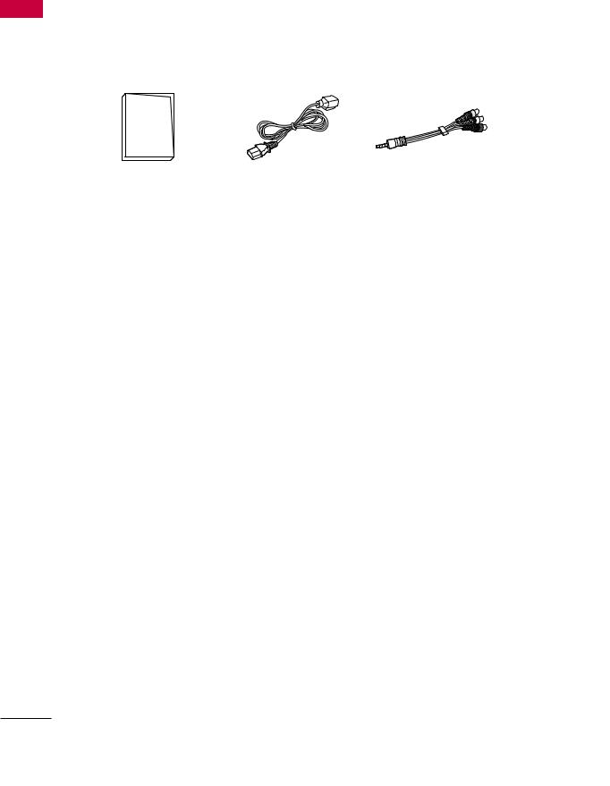
ACCESSORIES
Ensure that the following accessories are included with your TV. If an accessory is missing, please contact the dealer where you purchased the TV.
The accessories included may differ from the images below.
|
(For 22/26/32LQ630H) |
(For 26LQ630H/42CQ610H) |
|
|
|
|
|
|
Quick Reference Guide |
Power Cord |
A/V adapter cable |
Protective bracket and |
|
|
|
screw for power cord |
(For 22/26LQ630H) |
(For 32LQ630H) |
(For 42CQ610H) |
|
|
|
x 3 |
Cable holder |
Cable holder |
Protection cover |
(See p.15) |
(See p.15) |
(See p.9) |
8

PROTECTION COVER
Image shown may differ from your TV.
42CQ610H
Install the included PROTECTION COVER over the hole for the stand.
Press the Protection cover into the TV until you hear it click.
PREPARATION
9

PREPARATION
PREPARATION
FRONT PANEL INFORMATION
V Image shown may differ from your TV.
V NOTE: If your TV has a protection tape attached, remove the tape. And then wipe the TV with a cloth (If a polishing cloth is included with your TV, use it).
22LQ630H
Remote control and intelligent sensors
Power indicator |
SPEAKER
|
|
|
|
Touch Buttons |
CH |
VOL |
ENTER |
MENU |
INPUT |
CHANNEL |
VOLUME |
ENTER |
MENU |
INPUT POWER |
( , ) |
(+, -) |
Button |
Button |
Button Button |
Buttons |
Buttons |
|
|
|
26/32LQ630H
Remote control and intelligent sensors
Power indicator |
SPEAKER
 Touch Buttons
CHANNEL VOLUME POWER
( , ) (+, -) Button
Buttons Buttons
10
42CQ610H
SPEAKER
 Power/Standby Indicator
Illuminates red in standby mode.
Illuminates blue when the set is switched on.
Remote Control Sensor
CH |
CHANNEL( , ) |
|
Buttons |
||
|
||
VOL |
VOLUME (+, -) |
|
Buttons |
||
|
||
ENTER |
|
|
|
ENTER Button |
|
MENU |
|
|
|
MENU Button |
|
INPUT |
|

 INPUT Button

 POWER Button
PREPARATION
! NOTE
G If Installer menu item 027(HOSPITAL MODE) is set value 254(Default), standby indicator does not illuminate.
11

PREPARATION
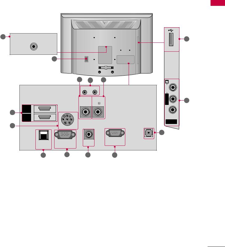
BACK PANEL INFORMATION
V Image shown may differ from your TV.
22LQ630H
PREPARATION
.1
.9 |
.6 |
|
14 |
.4 |
PILLOW SPEAKER |
|
UPDATE |
RESET |
|
.8 |
|
|
|
|
AUDIO IN SPEAKER |
CPU SERVICE |
|
|
(RGB/DVI) |
OUT(8 ) |
(SERVICE ONLY) ANTENNA |
|
RGB IN (PC) |
|
IN |
|
|
|
|
11 |
GAME CONTROL TV-LINK |
PTC SERVICE |
|
|
|||
|
/ M.P.I. |
CFG |
(SERVICE ONLY) |

 /DVI IN
 IN
IN
1 |
2 |
12 |
.7 |
.5 |
.3 |
.2 |
26/32LQ630H
14 |
RESET |
UPDATE |
.1
10 |
|
Healthcare Multimedia System |
|
ANTENNA IN |
|
|
GAME CONTROL |
TV-LINK SPEAKEROUT |
/ M.P.I. |
||
PTCSERVICE CPUSERVICE |
|
||
(SERVICEONLY)(SERVICEONLY) |
CFG |
(8 ) |
|
PILLOW SPEAKER
.2 |
|
|
|
|
|
|
|
|
.7 |
.8 |
.3 |
.4 |
.5 |
.6 |
|||||||
IN |
10 |
USB |
|
AV IN
AUDIO/VIDEO
13
AUDIOIN (RGB/DVI) |
.9 |
|
|
||
IN 1 |
10 |
|
USB |
||
|
||
IN (PC) |
11 |
|
RGB |
||
|
||
IN 2 |
|
|
|
12 |
|
/DVI IN 1 |
12 |
|
|
||
AVIN AUDIO/VIDEO |
13 |
|
|
12
42CQ610H |
|
|
|
|
|
|
|
|
|
|
2 |
ANTENNA IN |
|
|
|
|
|
INUSB |
10 |
PREPARATION |
|
|
|
|
|
|
|
|
||||
|
|
|
|
|
|
|
|
|||
|
|
|
1 |
|
|
|
|
|
|
|
|
|
|
.3 |
14 |
|
6 |
|
R |
|
|
|
|
|
|
|
|
|
|
|
||
|
|
|
RESET UPDATE |
|
|
AUDIO |
|
|
||
|
|
|
(SERVICEONLY) |
(8 |
) |
|
L/MONO |
|
|
|
|
|
|
PTC SERVICE |
SPEAKER OUT |
|
VIDEO |
13 |
|
||
|
12 |
2 |
|
|
|
|
|
|
|
|
|
HDMI |
|
|
|
|
|
|
|
|
|
|
HDMI |
1 |
|
|
|
|
|
|
|
|
|
/DVI IN |
|
|
|
|
|
|
AV IN |
|
|
|
8 |
|
|
|
|
|
TV-LINK |
|
|
|
|
|
|
|
|
|
|
|
|
||
|
|
|
PILLOW SPEAKER |
|
|
|
CFG |
|
|
|
|
|
|
|
|
|
|
|
.5 |
|
|
|
|
GAME |
RGB IN (PC) |
AUDIO IN |
|
RS-232C IN |
|
|
|
|
|
|
|
(SERVICE ONLY) |
|
|
|
||||
|
|
CONTROL/ |
|
(RGB/DVI) |
|
|
|
|
|
|
|
|
M.P.I |
|
|
|
|
|
|
|
|
|
|
7 |
11 |
.9 |
|
|
15 |
|
|
|
13

PREPARATION
PREPARATION
.1
.2
.3
.4
.5
.6
.7
.8
Power Cord Socket
For operation with AC power.
Caution: Never attempt to operate the TV on DC power.
ANTENNA IN
Connect over-the air signals to this jack.
PTC SERVICE (SERVICE ONLY)
Used for PTC software updates.
CPU SERVICE (SERVICE ONLY)
Used for CPU software updates.
TV - LINK CFG
Computer input for programming Free To Guest services.
SPEAKER OUT (8Ω)
For use with external speakers.
GAME CONTROL
Input port for third party game Controllers.
M. P. I.
Allows VOD/PPV devices or set-top boxes to control the TV.
PILLOW SPEAKER
Used to connect to pillow speaker.
.9 AUDIO IN (RGB/DVI)
1/8” headphone jack for analog PC audio input.
10 USB IN
Used for viewing multimedia files.
11 RGB IN (PC)
Analog PC Connection. Uses a D-sub 15-pin cable (VGA cable).
12 HDMI/DVI IN
Digital Connection.
Supports HD video and Digital audio.
Accepts DVI video using an adapter or HDMI to DVI cable (not included).
13 AV (Audio/Video) IN
Analog composite connection. Supports standard definition video only (480i).
Used for PC/DTV audio input jack
14 UPDATE
Software downloads and debug mode enable/ disable.
RESET
Hardware reset to PTC microcontroller.
15 RS-232C IN (SERVICE ONLY)
Used for software updates.
14

CABLE MANAGEMENT
22/32LQ630H
1 Gather and bind the cables with the CABLE HOLDER(S) on the TV back cover.
CABLE HOLDER
26LQ630H
1 Connect the cables as necessary.
To connect additional equipment, see the
EXTERNAL EQUIPMENT SETUP section. To help prevent the power cable from being removed by accident, secure the power cable with the included PROTECTIVE BRACKET /
SCREW.
PROTECTIVE BRACKET /SCREW


2 Gether and bind the cables with the CABLE HOLDER on the TV back cover.
CABLE HOLDER
PREPARATION
15

PREPARATION
PREPARATION
42CQ610H
1 Connect the cables as necessary.
To connect additional equipment, see the
EXTERNAL EQUIPMENT SETUP section. Secure the power cable with the PROTECTIVE BRACKET/SCREW as shown.
It will help prevent the power cable from being removed by accident.
PROTECTIVE BRACKET /SCREW
(This feature is not available for all models.)
2 Install the CABLE MANAGEMENT CLIP as
shown.
CABLE MANAGEMENT CLIP
3 Put the cables inside the CABLE MANAGEMENT CLIP and snap it closed.
16
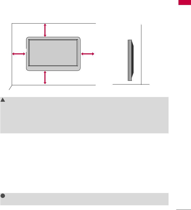
WALL MOUNT INSTALLATION
V Image shown may differ from your TV.
For proper ventilation, allow a clearance of 4 inches on all four sides.
4 inches
4 inches |
4 inches |
 4 inches
4 inches
! CAUTION
G Ensure adequate ventilation by following the clearance recommendations. G Do not mount near or above any type of heat source.
G Do not put this product next to the patient’s bed where it can be reached by the patient. G Install product in such a way that patients will not be able to touch this product
G This product should only be mounted on a wall.
KENSINGTON SECURITY SYSTEM
V This feature is not available for all models.
-The TV is equipped with a Kensington Security System connector on the back panel. Connect the Kensington Security System cable as shown below.
-For the detailed installation and use of the Kensington Security System, refer to the user’s guide provided with the Kensington Security System.
For further information, contact http://www.kensington.com, the internet homepage of the Kensington company. Kensington sells security systems for expensive electronic equipment such as notebook PCs and LCD projectors.
! NOTE
G The Kensington Security System is an optional accessory.
PREPARATION
17
PREPARATION
PREPARATION
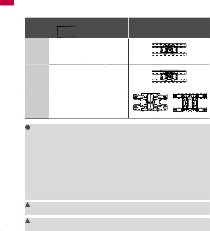
VESA WALL MOUNTING
Install your wall mount on a solid wall perpendicular to the floor. When attaching to other building materials, please contact your nearest installer.
If installed on a ceiling or slanted wall, it may fall and result in severe personal injury. We recommend that you use an LG brand wall mount when mounting the TV to a wall. LG recommends that wall mounting be performed by a qualified professional installer.
Model |
VESA (A * B) |
Standard |
Quantity |
Wall Mounting Bracket |
A |
Screw |
(sold separately) |
||
|
B |
|
22LQ630H |
100 * 100 |
M4 |
4 |
|
26LQ630H |
|
|||
|
|
|
|
|
|
|
|
LSW100B(G) |
|
32LQ630H |
200 * 100 |
M4 |
4 |
|
|
|
|
LSW100B(G) |
|
42CQ610H |
200 * 200 |
M6 |
4 |
|
|
|
|
LSW200BX(G) |
LSW220BX(G) |
! NOTE
G Screw length needed depends on the wall mount used. For further information, refer to the instructions included with the mount.
G Standard dimensions for wall mount kits are shown in the table.
G When purchasing our wall mount kit, a detailed installation manual and all parts necessary for assembly are provided.
G Do not use screws longer then the standard dimension, as they may cause damage to the inside of the TV.
G For wall mounts that do not comply with the VESA standard screw specifications, the length of the screws may differ depending on their specifications.
G Do not use screws that do not comply with the VESA standard screw specifications.
Do not use fasten the screws too strongly, this may damage the TV or cause the TV to a fall, leading to personal injury. LG is not liable for these kinds of accidents.
G LG is not liable for TV damage or personal injury when a non-VESA or non specified wall mount is used or the consumer fails to follow the TV installation instructions.
! CAUTION
G Do not install your wall mount kit while your TV is turned on. It may result in personal injury due to electric shock.
! WARNING
G To prevent injury, this apparatus must be securely attached to the wall in accordance with the installation instructions.
18

V To prevent damage, do not connect to the power outlet until all connections are made between the devices.
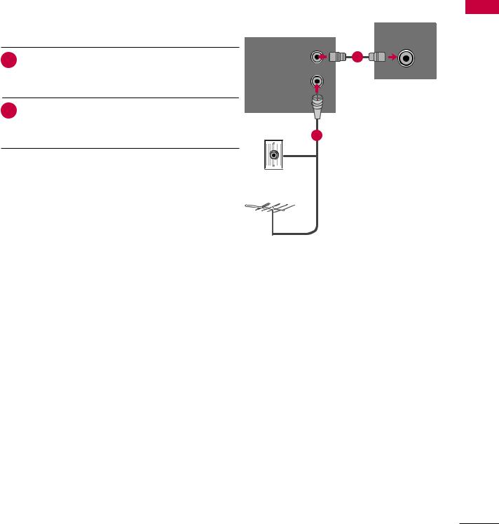
ANTENNA OR CABLE CONNECTION
1. Antenna (Analog or Digital)
Wall Antenna Socket or Outdoor Antenna without a Cable Box Connection. For optimum picture quality, adjust the direction if needed.
Wall |
Multi-family Dwellings/Apartments |
ANTENNA IN |
|
(Connect to wall antenna socket) |
|||
Antenna |
|
||
|
|
||
Socket |
|
|
|
Outdoor |
RF Coaxial Wire (75Ω) |
|
|
|
|
||
Antenna |
|
|
|
(VHF, UHF) |
Single-family Dwellings /Houses |
Copper Wire |
|
|
(Connect to wall jack for outdoor antenna) |
||
|
Be careful not to bend the copper wire |
||
|
|
||
|
|
when connecting the antenna. |
2. Cable
ANTENNA IN
Cable |
|
TV Wall |
|
Jack |
RF Coaxial Wire (75 Ω) |
V To improve the picture quality in a poor signal area, please purchase a signal amplifier and install properly. V If the antenna needs to be split for two TV’s, install a 2-Way Signal Splitter.
V If the antenna is not installed properly, contact your dealer for assistance.
PREPARATION
19

EXTERNALTERNAL EQUIPMENTEQUIPMENTS TUP SETUP
V To prevent the equipment damage, never plug in any power cords until you have finished connecting all equipment. V This part of EXTERNAL EQUIPMENT SETUP mainly uses the picture for 22LQ630H model.
HD RECEIVER SETUP
This TV can receive Digital Over-the-air or Digital Cable signals without an external digital set-top box.
However, if you do receive digital signals from a digital set-top box or other digital external device, refer to the figure as shown below.
SETUP EQUIPMENT EXTERNAL
HDMI Connection
1. How to connect
|
|
1 |
|
/DVI IN |
2 |
|
IN |
|
|
|
|
|
|
|
|
|
|||||
|
|
|
|
|
|
|
||||
|
|
|
|
|
|
|
||||
|
|
|
|
|
|
|
|
|
||
1 |
|
|
|
|
||||||
Connect the digital set-top box to HDMI/DVI IN 1 |
|
|
|
|
|
|
||||
OR jack on the TV. 
2 No separate audio connection is necessary. HDMI supports both audio and video.
|
|
1 |
|
|
|
|
|
2. How to use |
|
|
|
|
V Turn on the digital set-top box. |
|
|
|
(Refer to the owner’s manual for the digital set-top box.) |
|
|
|
V Select HDMI 1 or HDMI 2 input source with using the |
|
|
|
INPUT button on the remote control. |
|
HDMI-DTV OUTPUT |
|
|
|
|
HDMI-DTV |
|
|
|
Resolution |
Horizontal |
Vertical |
|
Frequency(kHz) |
Frequency(Hz) |
||
|
|||
720x480p |
31.47 |
59.94 |
|
31.47 |
60.00 |
||
|
|||
1280x720p |
44.96 |
59.94 |
|
45.00 |
60.00 |
||
|
|||
1920x1080i |
33.72 |
59.94 |
|
33.75 |
60.00 |
||
|
|||
|
67.50 |
60.00 |
|
|
67.432 |
59.939 |
|
1920x1080p |
27.00 |
24.00 |
|
26.97 |
23.976 |
||
|
|||
|
33.75 |
30.00 |
|
|
33.71 |
29.97 |
20
DVI to HDMI Connection
1.How to connect
1Connect the DVI output of the digital set-top box to the HDMI/DVI IN 1 jack on the TV.
2Connect the audio output of the digital set-top box to the AUDIO IN(RGB/DVI) or AV IN AUDIO jack on the TV.
2.How to use
V Turn on the digital set-top box.
(Refer to the owner’s manual for the digital set-top box.) V Select the HDMI 1 input source on the TV using the
INPUT button on the remote control.
! NOTE
G A DVI to HDMI cable or adapter is required for this connection. DVI doesn't support audio, so a separate audio connection is necessary.
AUDIO IN (RGB/DVI)

 /DVI IN
 IN
IN
1 |
2 |
|
1 |
|
2 |
|
|
|
|
|
|
|
|
|
|
|
|
|
|
|
|
|
DVI-DTV OUTPUT |
L |
R |
SETUP EQUIPMENT EXTERNAL
21

EXTERNAL EQUIPMENT SETUP
SETUP EQUIPMENT EXTERNAL
DVD SETUP
HDMI Connection
1. How to connect
|
|
|
|
|
/DVI IN |
|
IN |
|
|
|
|
|
|
|
|
|
|
|
|||
|
|
|
|
|
|
|
|
|
||
|
|
|
|
|
|
|
|
|
||
|
|
1 |
2 |
|
|
|
|
|
||
|
|
|
|
|
|
|||||
|
1 Connect the HDMI output of the DVD to the |
|
|
OR |
|
|
|
|
|
|
|
|
|
|
|
|
|
|
|||
|
HDMI/DVI IN 1 jack on the TV. |
|
|
|
|
|
|
|
||
|
|
|
|
|
|
|
|
|
||
|
2 No separate audio connection is necessary. |
|
|
|
|
|
|
|
|
|
|
HDMI supports both audio and video. |
|
|
|
|
|
|
|
|
|
|
|
|
1 |
|
|
|
|
|
||
|
|
|
|
|
|
|
|
|
|
|
2. How to use |
|
|
|
|
|
|
|
|
||
V Select the HDMI 1 or HDMI 2 input source on the TV |
|
|
|
|
|
|
|
|
||
|
using the INPUT button on the remote control. |
|
|
|
|
|
|
|
|
|
|
|
|
|
|
|
|
|
|
||
V Refer to the DVD player's manual for operating |
|
|
|
|
|
|
|
|
||
|
instructions. |
HDMI-DTV OUTPUT |
|
|
|
|
|
|||
|
|
|
|
|
|
|
|
|
|
|
22
VCR SETUP
V To avoid picture noise (interference), leave an adequate distance between the VCR and TV.
V If the 4:3 picture format is used; the fixed images on the sides of the screen may remain visible on the screen. This phenomenon is common to all TVs and is not covered by warranty.
Antenna Connection
1. How to connect
ANTENNA IN
1 |
Connect the RF antenna out socket of the VCR to the |
|
|
|
|
|
|
|
1 |
|
|
|
|
|
|
|
ANT OUT |
||
|
ANTENNA IN socket on the TV. |
IDEO |
|
L |
|
|
R |
|
|
2 |
|
|
|
||||||
|
|
|
|
|
|
|
|
||
Connect the antenna cable to the RF antenna in |
|
|
|
|
|
|
|
|
|
|
socket of the VCR. |
Wall Jack |
2 |
||||||
|
|
||||||||
2. How to use
V Set VCR output switch to 3 or 4 and then tune TV to the
same channel number. |
Antenna |
|
|
V Insert a video tape into the VCR and press PLAY on the |
|
VCR. (Refer to the VCR owner’s manual.) |
|
SETUP EQUIPMENT EXTERNAL
23

EXTERNAL EQUIPMENT SETUP
Composite (RCA) Connection
EXTERNAL |
1. How to connect |
|
|
|
|
|
1 Connect the AUDIO/VIDEO jacks between TV and |
|
|
|
|
EQUIPMENT |
|
VCR. Match the jack colors (Video = yellow, Audio Left |
|
= white, and Audio Right = red). |
|
|
|
|
|
2. How to use |
SETUP |
V Insert a video tape into the VCR and press PLAY on the |
V Select the AV input source on the TV using the INPUT |
|
|
VCR. (Refer to the VCR owner’s manual.) |
|
button on the remote control. |
! NOTE
G If you have a mono VCR, connect the audio cable from the VCR to the AUDIO L(MONO) jack of the TV.
AV IN (AUDIO/VIDEO)
1
R L VIDEO
24
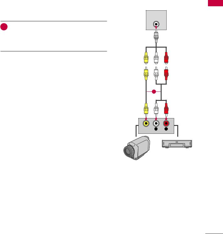
OTHER A/V SOURCE SETUP
1.How to connect
1Connect the AUDIO/VIDEO jacks between TV and external equipment. Match the jack colors (Video = yellow, Audio Left = white, and Audio Right = red).
2.How to use
V Select the AV input source on the TV using the INPUT button on the remote control.
V If connected to AV IN input, select the AV input source on the TV.
V Operate the corresponding external equipment.
AV IN (AUDIO/VIDEO)
1
VIDEO L R
Video Game Set
Camcorder
SETUP EQUIPMENT EXTERNAL
25

EXTERNAL EQUIPMENT SETUP
SETUP EQUIPMENT EXTERNAL
PILLOW SPEAKER SETUP
V Connect a pillow speaker to the LCD TV/Monitor.
How to connect
Connect the pillow speaker (see example at right) to the PILLOW SPEAKER interface on the rear jack panel of the TV.
Use a pillow speaker that is a UL recognized pendant control bearing the warning:
“Risk of fire if used in oxygen enriched atmosphere. Keep pendant control away from oxygen equipment.”
Controlling the TV with Serial Data
These TV models are capable of being controlled by a single-wire, serial data signal. This is an LG patented technology and is being implemented by certain brands of “smart” pillow speakers.
Pillow Speaker Interface
This connector provides an interface for patient-pendant remote control or entertainment audio and nurse call systems. All lines are isolated from the AC power line. (Optoisolators isolate the control lines, and a transformer isolates the audio.) Earth ground is provided on pin 4 (Common) in the default configuration (e.g., for Zenith/Philips pillow speakers). For negative voltage configuration (e.g., for RCA pillow speakers), +5 volts is provided on pin 4 (Common), with pin 3 (Channel Up/Data In) referenced to ground.
The following table describes the pillow speaker interface pinout (see also diagram at right).
Typical Pillow Speaker
(Serial Data Control)
PILLOW SPEAKER
Typical Schematic for
Analog Pillow Speaker
Pillow Speaker Interface Pinout
Pin No. |
Description |
|
|
|
|
1 |
Analog external control for TV ON/OFF. |
|
2 |
No connection |
|
3 |
Analog external control for Channel Up or Serial |
|
Data in. |
||
|
||
4 |
Common connection for control, data, and audio |
|
output. |
||
|
||
|
Isolated Audio Output. Nominal 14 ohm source |
|
5 |
impedance with short circuit protection. Intended |
|
for a pillow speaker with a lowimpedance, pad- |
||
|
||
|
type volume control. |
|
6 |
Analog external control for Channel Down. |
Controlling the TV with Mechanical Switches
A typical analog pillow speaker with mechanical switches will momentarily connect pin 1, 3, or 6 to pin 4 (Common) to control Power ON/ OFF, Channel Up, or Channel Down (see schematic above). These pins are at +13 volts DC (when measured from pin 4) with the switches open. Typical current draw is 8 mA when a switch is closed. (This operation is identical to previous models using the 5-wire interface, except that only +7 volts DC was supplied and current draw was only 2.5 mA.)
26

PC SETUP
This TV provides Plug and Play capability, meaning that the PC adjusts automatically to the TV's settings.
VGA (D-Sub 15-pin) Connection
1. How to connect
RGB IN (PC)
1 Connect the VGA output of the PC to the RGB IN (PC) jack on the TV.
2 Connect the PC audio output to the AUDIO IN (RGB/DVI) jack on the TV.
2. How to use |
1 |
2 |
|
V Turn on the PC and the TV.
V Select the RGB-PC input source on the TV using the
INPUT button on the remote control.
RGB OUTPUT |
AUDIO |
|
|
Supported Display Specifications
(RGB-PC, HDMI-PC)
Resolution
Horizontal Vertical
Frequency(kHz) Frequency(Hz)
640x350 |
31.468 |
70.09 |
720x400 |
31.469 |
70.08 |
640x480 |
31.469 |
59.94 |
800x600 |
37.879 |
60.31 |
1024x768 |
48.363 |
60.00 |
1280x768 |
47.776 |
59.87 |
1360x768 |
47.712 |
60.015 |
! NOTE
G To get the the best picture quality, adjust the PC graphics card to 1360x768.
G Depending on the graphics card, DOS mode may not work if a HDMI to DVI Cable is in use.
G In PC mode, there may be noise associated with the resolution, vertical pattern, contrast or brightness. If noise is present, change the PC output to another resolution, change the refresh rate to another rate or adjust the brightness and contrast on the PICTURE menu until the picture is clear.
G Avoid keeping a fixed image on the screen for a long period of time. The fixed image could become permanently imprinted on the screen.
G The synchronization input form for Horizontal and Vertical frequencies is separate.
G Depending on the graphics card, some resolution settings may not allow the image to be positioned on the screen properly.
SETUP EQUIPMENT EXTERNAL
27

EXTERNAL EQUIPMENT SETUP
SETUP EQUIPMENT EXTERNAL
DVI to HDMI Connection
1.How to connect
1Connect the DVI output of the PC to the HDMI/DVI IN 1 jack on the TV.
2Connect the PC audio output to the AUDIO IN (RGB/DVI) jack on the TV.
2.How to use
V Turn on the PC and the TV.
V Select the HDMI 1 input source on the TV using the INPUT button on the remote control.
AUDIO IN (RGB/DVI)
|
|
|
|
|
|
|
|
|
|
|
|
|
|
|
|
|
|
|
|
|
|
|
|
|
|
|
|
|
|
|
|
|
|
|
|
|
|
|
|
|
|
|
|
|
|
|
|
|
|
|
|
|
|
|
|
|
|
|
|
|
|
|
|
|
|
|
|
|
|
|
|
|
|
|
|
|
|
|
|
1 |
|
/DVI IN |
2 |
|
|
IN |
|
|
|
|
|
|
|
||
|
|
|
|
|
|
|
|
|
|
||||||
|
|
|
|
|
|
|
|
|
|
||||||
|
|
|
|
|
|
|
|
|
|
||||||
|
|
|
|
|
|
|
|
|
|
|
|
|
|
||
|
|
|
|
|
|
|
|
|
|
|
|
|
|
|
|
1 |
|
2 |
|
|
|
|
|
|
|
|
|
|
|
|
|
|
|
|
|
DVI-DTV OUTPUT |
L |
R |
|
|
|
28
Screen Setup for PC mode
Selecting Resolution
You can choose the resolution in RGB-PC mode.
The Position, Phase, and Size can also be adjusted.
PICTURE |
Move |
Enter |
SCREEN |
Move |
Prev. |
|
|
|
|||
•Sharpness |
70 |
|
Resolution |
1024 x 768 |
|
|
|
|
|||
|
|
|
|
||
•Color |
60 |
|
Auto Config. |
1280 x 768 |
|
|
|
|
|
|
|
•Tint |
90 |
|
|
1360 x 768 |
|
•Color Temp. |
50 |
|
Position |
|
|
|
|
|
|||
|
|
|
|
||
•Advanced Color |
|
Size |
|
|
|
•Picture Reset |
|
|
Phase |
|
|
Screen (RGB-PC) |
|
|
|
|
|
|
|
|
|
|
|
|
|
|
Reset |
|
|
1 MENU
Select PICTURE.
2

ENTER
Select Screen (RGB-PC).
3

ENTER
Select Resolution.
4

ENTER
Select the desired resolution.
5
ENTER
SETUP EQUIPMENT EXTERNAL
29

EXTERNAL EQUIPMENT SETUP
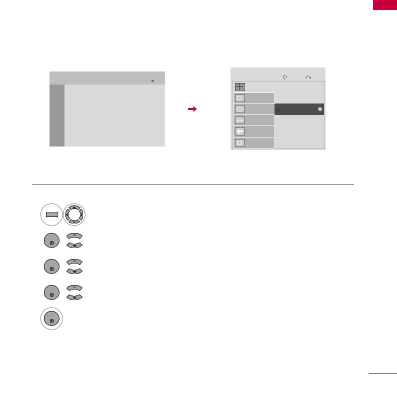
Auto Configure
Automatically adjusts picture position and minimizes image instability. After adjustment, if the image is still not correct, try using the manual settings or a different resolution or refresh rate on the PC.
SETUP EQUIPMENT EXTERNAL
PICTURE |
Move |
Enter |
SCREEN |
Move |
Prev. |
|
|
|
|||
•Sharpness |
70 |
|
Resolution |
|
|
•Color |
60 |
|
Auto Config. |
|
|
|
|
|
|
|
|
•Tint |
90 |
|
|
To Set |
|
•Color Temp. |
50 |
|
Position |
|
|
|
|
Yes |
No |
||
•Advanced Color |
|
Size |
|||
|
|
|
|||
|
|
|
|
|
|
•Picture Reset |
|
|
Phase |
|
|
Screen (RGB-PC) |
|
|
|
|
|
|
|
|
|
|
|
|
|
|
Reset |
|
|
1 MENU
Select PICTURE.
2 

ENTER
Select Screen (RGB-PC).
3 

ENTER
Select Auto config.
4 
ENTER
Select Yes.
5
ENTER
• If the position of the image is still not correct, try Auto adjustment again.
•If picture needs to be adjusted again after
Auto adjustment in RGB-PC, you can adjust the Position, Size or Phase.
30
Loading...