


 Loading...
LG Electronics 19 9L S4D, 19 9L G30, 22 2L G30, 22 2L S4D, 26 6L G30 User Manual
...ENGLISH
Trade Mark of the DVB Digital Video Broadcasting Project (1991 to 1996)
ID Number(s): 5018: 22LS4D-ZC 5107: 42PG1000-ZA 5109: 42PG3000-ZA 5088: 19LG3000-ZA 5080: 26LG3000-ZA 5087: 37LG3000-ZA 5085: 32LG5000-ZA 5083: 42LG5000-ZA 5081: 52LG5000-ZA 5386: 47LG5010-ZD 5388: 37LG5010-ZD 5390: 52LG5020-ZB 5392: 42LG5020-ZB 5394: 32LG5020-ZB 5396: 47LG5030-ZE 5398: 37LG5030-ZE
5019: 19LS4D-ZC 5106: 50PG1000-ZA 5108: 50PG3000-ZA 5090: 22LG3000-ZA 5089: 32LG3000-ZA 5086: 42LG3000-ZA 5084: 37LG5000-ZA 5082: 47LG5000-ZA 5385: 52LG5010-ZD 5387: 42LG5010-ZD 5389: 32LG5010-ZD 5391: 47LG5020-ZB 5393: 37LG5020-ZB 5395: 52LG5030-ZE 5397: 42LG5030-ZE 5399: 32LG5030-ZE
Downloaded From TV-Manual.com Manuals
LCD TV |
PLASMA TV |
OWNER’S MANUAL |
|
LCD TV MODELS |
PLASMA TV MODELS |
19LS4D* 42LG30** 22LS4D* 32LG50** 19LG30** 37LG50** 22LG30** 42LG50** 26LG30** 47LG50** 32LG30** 52LG50** 37LG30**
42PG10** 50PG10** 42PG30** 50PG30**
Please read this manual carefully before operating your TV.
Retain it for future reference.
Record model number and serial number of the TV. Refer to the label on the back cover and quote this information.
To your dealer when requiring service.
Downloaded From TV-Manual.com Manuals
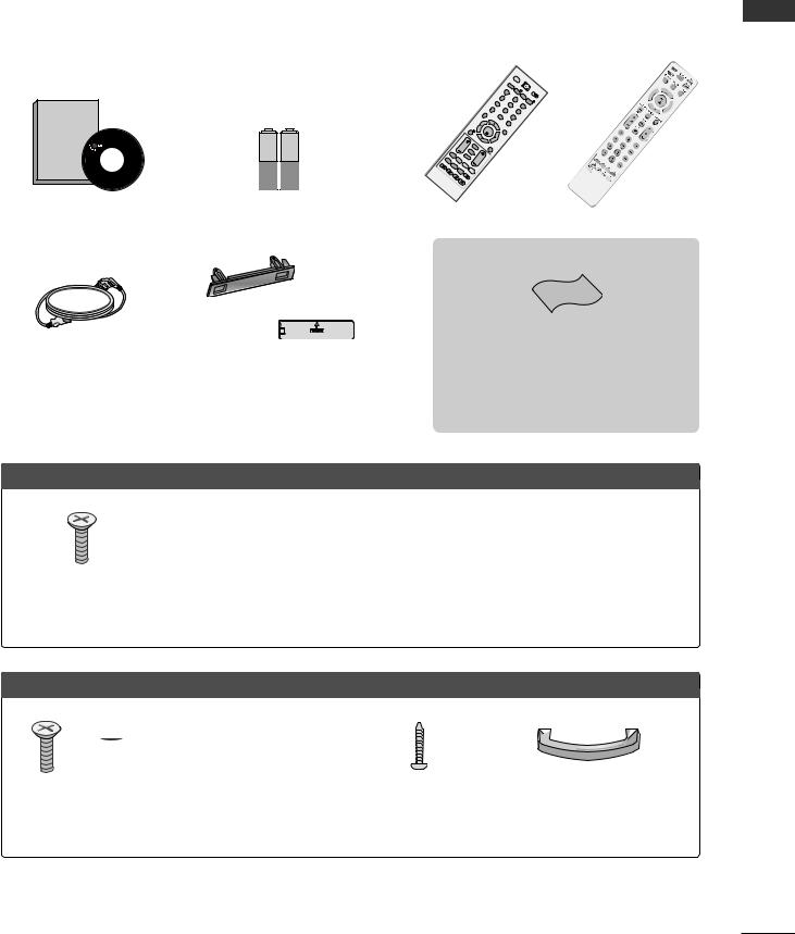
ACCESSORIES
Ensure that the following accessories are included with your TV. If an accessory is missing, please contact the dealer where you purchased the TV.
■ Image shown may differ from your TV.
Owner's
Manual
Owner’s manual
|
|
|
INF |
|
|
|
O i |
|
|
V |
BA |
|
|
OL |
|
|
|
|
CK |
|
|
|
* |
|
|
F |
|
R |
|
AV |
P |
ATIO |
|
|
R |
IN |
SLE |
|
|
DEX |
EP |
SUBTITLE |
|
IME |
|
|
|
T |
|
UPDATE |
|
|
LD |
||
|
HO |
|
|
|
|
REVEAL? |
|
|
|
|
TV |
|
|
D/A |
|
|
|
TV/RADIO |
TEXT |
|
|
|
|
|
1 |
|
|
4 |
|
2 |
|
7 |
|
5 |
|
L |
8 |
|
|
IST |
|
6 |
|
ME |
|
|
|
NU |
|
|
|
0 |
|
9 |
|
|
Q. |
|
|
|
VIEW |
|
|
OK |
E |
|
|
XIT |
|
|
|
G |
|
|
|
UIDE |
|
|
|
P |
|
OW |
|
ER |
|
|
IN |
I/II |
PU |
T |
|
MU |
|
TE |
|
3
or
R ATI
Owner’s Manual |
Batteries |
Remote Control |
or
Power Cord
Protection Cover
(Except for 19/22LS4D*)
PLASMA TV models
This feature is not available for all models.
Polishing Cloth
Polishing cloth for use on the screen.
Lightly wipe any stains or fingerprints on the surface of the TV with the polishing cloth.
Do not use excessive force. This may cause scratching or discolouration.
x 4 |
|
|
|
Bolts for stand assembly |
Cable Holder |
Cable management clip |
Cable management clip |
(Refer to p.10) |
(42PG10**, 42PG30**: 1EA, |
(Only 42/50PG10**) |
(Only 42/50PG30**) |
(Only 42PG10**, 42PG30**) |
50PG10**, 50PG30**: 2EA) |
|
|
LCD TV models
x 4 |
x 4 |
x 4 |
|
|
Bolts for stand assembly |
Bolts for stand assembly |
1-screw for stand fixing |
Cable management clip |
|
(Refer to p.10) |
|
(Refer to p.10) |
(Refer to p.5) |
(Only 19/22LS4D*) |
(Only 32/37/42LG50**, |
(Only 19/22LG30**) |
(Only 26/32LG30**, |
|
|
26/32/37LG30**) |
|
|
32LG50**) |
|
ACCESSORIES
1
Downloaded From TV-Manual.com Manuals

CONTENTS
ACCESSORIES . . . . . . . . . . . . . . . . . . . . . . . . . . . . . . . . . . . . . . . . . . . . . 1
|
PREPARATION |
|
CONTENTS |
Stand Installation . . . . . . . . . . . . . . . . . . . . . . . . . . . |
10 |
|
Front Panel Controls . . . . . . . . . . . . . . . . . . . . . . . |
. 4 |
|
Back Panel Information . . . . . . . . . . . . . . . . . . . . . |
. 7 |
|
Detaching Stand . . . . . . . . . . . . . . . . . . . . . . . . . . . |
12 |
|
Please set it up carefully so the product |
|
|
does not fall over . . . . . . . . . . . . . . . . . . . . . . . . . . |
13 |
|
Back Cover for Wire Arrangement . . . . . . . . . . . . . |
14 |
|
Positioning Your Display . . . . . . . . . . . . . . . . . . . . . |
16 |
|
Location . . . . . . . . . . . . . . . . . . . . . . . . . . . . . . . . . . |
16 |
|
Kensington Security System . . . . . . . . . . . . . . . . . . |
16 |
|
Desktop Pedestal Installation . . . . . . . . . . . . . . . . . |
17 |
|
Wall Mount: Horizontal Installation . . . . . . . . . . . . |
17 |
|
Antenna Connection . . . . . . . . . . . . . . . . . . . . . . . . |
18 |
EXTERNAL EQUIPMENT SETUP
HD Receiver Setup . . . . . . . . . . . . . . . . . . . . . . . . 19 Digital Audio out Setup . . . . . . . . . . . . . . . . . . . . . 20 DVD Setup . . . . . . . . . . . . . . . . . . . . . . . . . . . . . . . . 21 VCR Setup . . . . . . . . . . . . . . . . . . . . . . . . . . . . . . . . 23 Other A/V Source Setup . . . . . . . . . . . . . . . . . . . . 25 Insertion of CI Module . . . . . . . . . . . . . . . . . . . . . . 26 PC Setup . . . . . . . . . . . . . . . . . . . . . . . . . . . . . . . . . 26
- Screen Setup for PC Mode . . . . . . . . . . . . . . . 30
WATCHING TV / PROGRAMME CONTROL
Remote Control Key Functions . . . . . . . . . . . . . . . . 34 Turning on the TV . . . . . . . . . . . . . . . . . . . . . . . . . . 40 Programme Selection . . . . . . . . . . . . . . . . . . . . . . . 40 Volume Adjustment . . . . . . . . . . . . . . . . . . . . . . . . . 40 On-Screen Menus Selection and Adjustment . . . . 41 Auto Programme Tuning . . . . . . . . . . . . . . . . . . . . . 42 Manual Programme Tuning (In Digital Mode) . . . . 43 Manual Programme Tuning (In Analogue Mode) . . 44 Programme Edit . . . . . . . . . . . . . . . . . . . . . . . . . . . . 46 Booster . . . . . . . . . . . . . . . . . . . . . . . . . . . . . . . . . . 49
2
Software Update . . . . . . . . . . . . . . . . . . . . . . . . . . . 50
Diagnostics . . . . . . . . . . . . . . . . . . . . . . . . . . . . . . . 51
CI Information . . . . . . . . . . . . . . . . . . . . . . . . . . . . . 52
Selecting the Programme Table . . . . . . . . . . . . . . 53
SIMPLINK . . . . . . . . . . . . . . . . . . . . . . . . . . . . . . . . 54
Input Label . . . . . . . . . . . . . . . . . . . . . . . . . . . . . . . 56
AV Mode . . . . . . . . . . . . . . . . . . . . . . . . . . . . . . . . . 57
EPG (ELECTRONIC PROGRAMME GUIDE) (IN DIGITAL MODE)
Switch On/ Off EPG . . . . . . . . . . . . . . . . . . . . . . . . 58 Select Programme . . . . . . . . . . . . . . . . . . . . . . . . . . 58 Button Function in NOW/NEXT Guide Mode . . . . . 59 Button Function in 8 Day Guide Mode . . . . . . . . . . 59 Button Function in Date Change Mode . . . . . . . . . . 59 Button Function in Extended Description Box . . . . . 60 Button Function in Record/Remind Setting Mode . . 60 Button Function in Schedule List Mode . . . . . . . . . . 60
PICTURE CONTROL |
|
Picture Size (Aspect Ratio) Control . . . . . . . . |
. . . . 61 |
Preset Picture Settings |
|
- Picture Mode-Preset . . . . . . . . . . . . . . . . |
. . . . 63 |
- Auto Colour Tone Control (Warm/Medium/Cool) . |
. . . .64 |
Manual Picture Adjustment |
|
- Picture Mode-User option . . . . . . . . . . . . |
. . . 65 |
- Picture Mode-Expert Control . . . . . . . . . |
. . . 66 |
Picture Improvement Technology . . . . . . . . . . . . . . |
. . . 67 |
Advanced - Film Mode . . . . . . . . . . . . . . . . . . . |
. . . 68 |
Advanced - Black(Darkness) Level . . . . . . . . . . |
. . . 69 |
Eye Care . . . . . . . . . . . . . . . . . . . . . . . . . . . . . . |
. . . 70 |
Picture Reset . . . . . . . . . . . . . . . . . . . . . . . . . . . |
. . . 71 |
Image Sticking Minimization (ISM) Method |
. . . . 72 |
Power Saving Picture Mode . . . . . . . . . . . . . . . |
. . . 73 |
Downloaded From TV-Manual.com Manuals

SOUND & LANGUAGE CONTROL
Auto Volume Leveler . . . . . . . . . . . . . . . . . . . . . . . . 74 Preset Sound Settings - Sound Mode . . . . . . . . . . 75 Sound Setting Adjustment - User Mode . . . . . . . . . . 76 Balance . . . . . . . . . . . . . . . . . . . . . . . . . . . . . . . . . . . 77 TV Speakers On/ Off Setup . . . . . . . . . . . . . . . . . 78 Selecting Digital Audio Out . . . . . . . . . . . . . . . . . 79 Audio Reset . . . . . . . . . . . . . . . . . . . . . . . . . . . . . . . 80 I/II
- Stereo/Dual Reception (In Analogue Mode Only) . . . . 81 - NICAM Reception (In Analogue Mode Only) . . . . . . . 82 - Speaker Sound Output Selection . . . . . . . . . . 82
On-Screen Menu Language/Country Selection . . . . . . . . 83 Language selection (In Digital Mode only) . . . . . . 84
DIGITAL TELETEXT
Teletext within Digital Service . . . . . . . . . . . . . . . 95 Teletext in Digital Service . . . . . . . . . . . . . . . . . . 95
APPENDIX |
|
Initializing (Reset to original factory setting) |
. . . . 96 |
Troubleshooting . . . . . . . . . . . . . . . . . . . . . . . . |
. . . . 97 |
Maintenance . . . . . . . . . . . . . . . . . . . . . . . . . . |
. . . . 99 |
Product Specifications . . . . . . . . . . . . . . . . . . . |
. . 100 |
Programming the Remote Control . . . . . . . . . . |
. . 103 |
IR Codes . . . . . . . . . . . . . . . . . . . . . . . . . . . . . . |
. . 105 |
External Control Device Setup . . . . . . . . . . . . |
. . 107 |
CONTENTS
TIME SETTING
Clock Setup . . . . . . . . . . . . . . . . . . . . . . . . . . . . . . . 85
Auto On/ Off Timer Setting . . . . . . . . . . . . . . . . . . 86
Auto Shut-off Setting . . . . . . . . . . . . . . . . . . . . . . . 87
Time Zone Setup . . . . . . . . . . . . . . . . . . . . . . . . . . . 88
Sleep Timer Setting . . . . . . . . . . . . . . . . . . . . . . . . . 88
PARENTAL CONTROL / RATINGS
Set Password & Lock System . . . . . . . . . . . . . . . . . 89
Block Programme . . . . . . . . . . . . . . . . . . . . . . . . . . . 90
Parental Control . . . . . . . . . . . . . . . . . . . . . . . . . . . . 91
Key Lock . . . . . . . . . . . . . . . . . . . . . . . . . . . . . . . . . 92
TELETEXT
Switch On/ Off . . . . . . . . . . . . . . . . . . . . . . . . . . . . 93
SIMPLE Text . . . . . . . . . . . . . . . . . . . . . . . . . . . . . . . 93
TOP Text . . . . . . . . . . . . . . . . . . . . . . . . . . . . . . . . . 93
FASTEXT . . . . . . . . . . . . . . . . . . . . . . . . . . . . . . . . . 94
Special Teletext Functions . . . . . . . . . . . . . . . . . . . . 94
3
Downloaded From TV-Manual.com Manuals

PREPARATION
PREPARATION
FRONT PANEL CONTROLS
■Image shown may differ from your TV.
■If your TV has a protection film attached, remove the film and then wipe the TV with a polishing cloth.
PLASMA TV Models : 42/50PG30**
Remote Control Sensor
POWER
Power/Standby Indicator
• illuminates red in standby mode.
• illuminates green when the TV is switched on.
INPUT MENU OK -
-  +
+  P
P
|
|
|
|
|
|
|
INPUT |
MENU |
OK |
VOLUME |
PROGRAMME |
||
|
|
|
|
|
|
|
PLASMA TV Models : 42/50PG10**
|
|
|
Remote Control Sensor |
|
|
|
|
|
Power/Standby Indicator |
||
|
|
|
• illuminates red in standby mode. |
||
|
|
|
• illuminates green when the TV is switched on. |
||
INPUT |
MENU |
OK |
- |
+ |
P |
POWER INPUT |
MENU |
OK |
|
VOLUME |
PROGRAMME |
4
Downloaded From TV-Manual.com Manuals
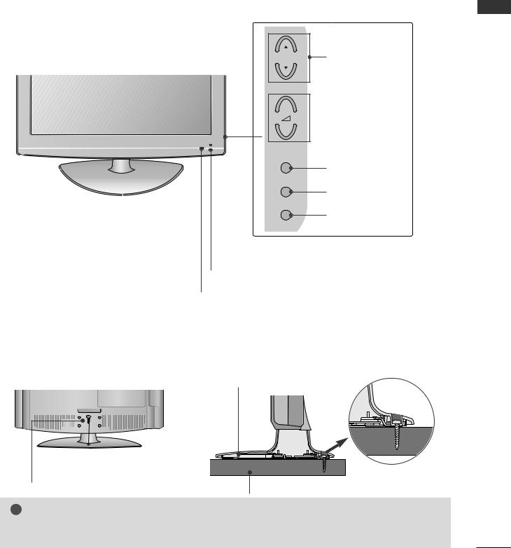
LCD TV Models :
26/32/37/42LG30**, 32/37/42/47/52LG50**
POWER
Remote Control Sensor
Power/Standby Indicator
•illuminates red in standby mode.
•illuminates blue when the TV is switched on.
Note: You can adjust Power Indicator in the OPTION menu.
P |
PROGRAMME |
+
 VOLUME
-
OK
OK
MENU
MENU
INPUT
INPUT
Intelligent Sensor
Adjusts picture according to the surrounding conditions. (32/37/42/47/52LG50** only)
PREPARATION
Attaching the TV to a desk (Only 26/32LG30**, 32LG50**)
The TV must be attached to desk so it cannot be pulled in a forward/backward direction, potentially causing injury or damaging the product. Use only an attached screw.
1-Screw
(provided as parts of the product)
Stand |
Desk
! WARNING
GTo prevent TV from falling over, the TV should be securely attached to the floor/wall per installation instructions. Tipping, shaking, or rocking the machine may cause injury.
5
Downloaded From TV-Manual.com Manuals

PREPARATION
PREPARATION
LCD TV Models : 19/22LG30**
INPUT |
MENU |
OK |
VOLUME |
PROGRAMME |
||
|
|
|
|
|
|
|
|
|
|
|
|
|
|
INPUT MENU OK |
- |
+ |
P |
POWER
Remote Control Sensor
Power/Standby Indicator
• illuminates red in standby mode.
• illuminates blue when the TV is switched on.
Note: You can adjust Power Indicator in the OPTION menu.
LCD TV Models : 19/22LS4D*
POWER |
INPUT |
MENU |
OK |
VOLUME |
PROGRAMME |
||
|
|
|
|
|
|
|
|
|
|
|
|
|
|
|
|
/I |
INPUT MENU OK |
VOL |
PR |
Remote Control Sensor
Power/Standby Indicator
• illuminates red in standby mode.
• illuminates green when the TV is switched on.
6
Downloaded From TV-Manual.com Manuals

BACK PANEL INFORMATION
A Image shown may differ from your TV.
PLASMA TV Models : 42/50PG10**, 42/50PG30**
|
|
|
|
10 |
|
1 |
|
|
|
|
|
5 |
|
|
|
|
|
HDMI/DVI IN |
|
|
ONLY |
|
|
2 |
3 |
4 |
11 |
||
SERVICE |
|||||
|
|
|
|
Only 42/50PG10**
HDMI IN |
|
|
|
S-VIDEO |
|
3 |
|
|
|
|
|
|
|
|
|
R |
|
2 |
|
|
|
AUDIO |
12 |
|
|
|
|
||
|
|
|
|
L/MONO |
|
1 |
|
|
|
|
|
|
|
|
VIDEO |
|
|
HDMI/DVI IN |
|
|
|
|
|
|
|
|
|
AV IN 3 |
|
5 |
6 |
7 |
8 |
9 |
|
1Power Cord Socket
This TV operates on an AC power. The voltage is indicated on the Specifications page. Never attempt to operate the TV on DC power.
2RGB/DVI Audio Input
Connect the audio from a PC or DTV.
3OPTICAL DIGITAL AUDIO OUT
Connect digital audio from various types of equipment. Note: In standby mode, these ports do not work.
4Euro Scart Socket (AV1/AV2)
Connect scart socket input or output from an external device to these jacks.
5HDMI Input
Connect a HDMI signal to HDMI IN. Or DVI (VIDEO) signal to HDMI/DVI port with DVI to HDMI cable.
6RGB Input
Connect the output from a PC.
7RS-232C IN (CONTROL & SERVICE) PORT
Connect to the RS-232C port on a PC.
8Component Input
Connect a component video/audio device to these jacks.
9Antenna Input
Connect RF antenna to this jack.
10PCMCIA (Personal Computer Memory Card International Association) Card Slot
(This feature is not available in all countries.)
11SERVICE ONLY PORT
12Audio/Video Input (Only 42/50PG30**)
Connect audio/video output from an external device to these jacks.
S-Video Input (Only 42/50PG30**)
Connect S-Video out from an S-VIDEO device.
PREPARATION
7
Downloaded From TV-Manual.com Manuals

PREPARATION
PREPARATION
8
LCD TV Models: |
|
|
|
|
|
SLOT |
|
|
19/22/26/32/37/42LG30** |
|
|
||||||
|
CARD |
|
||||||
32/37/42/47/52LG50** |
|
|
|
|||||
|
|
|
|
|
|
|
PCMCIA |
10 |
|
|
|
|
|
|
|
|
|
|
|
|
|
|
|
|
IN 3 |
5 |
|
|
|
|
|
|
|
HDMI |
|
|
|
|
|
|
|
|
|
|
|
13 |
|
2 |
3 |
1 |
4 |
|
|
|
|
|
|
OPTICAL |
COMPONENT |
|
|
|
|
USB IN |
|
AUDIO IN |
IN |
AV 2 |
S-VIDEO |
|
|
|
|
(RGB/DVI) |
DIGITAL |
AV 1 |
R |
|
||
|
SERVICE ONLY |
|
|
AUDIO OUT |
VIDEO |
|
L/MONOAUDIO |
|
|
HDMI/DVI IN |
|
|
|
|
11 |
||
|
|
|
|
|
|
|
||
|
|
|
|
|
|
|
|
|
|
2 |
|
RGB IN (PC) |
|
|
VIDEO |
|
|
|
|
|
|
|
|
|||
|
|
|
|
|
|
|
||
|
|
|
|
|
|
|
AV IN 3 |
|
|
1(DVI) |
|
|
|
AUDIO |
|
|
12 |
|
|
|
RS-232C IN |
|
|
|||
|
|
|
|
H/P |
|
|||
|
|
|
(CONTROL & SERVICE) |
|
|
|
||
|
|
|
|
|
|
|
ANTENNA IN |
|
|
5 |
6 |
7 |
|
8 |
|
9 |
|
1 |
Power Cord Socket |
|
|
|
|
8 |
Component Input |
|
|
This TV operates on an AC power. The voltage is |
|
Connect a component video/audio device to |
|||||
|
indicated on the Specifications page. Never |
|
these jacks. |
|
||||
|
attempt to operate the TV on DC power. |
|
Antenna Input |
|
||||
|
|
|
|
|
|
9 |
|
|
2 |
RGB/DVI Audio Input |
|
|
|
|
|
Connect RF antenna to this jack. |
|
|
Connect the audio from a PC or DTV. |
|
|
PCMCIA (Personal Computer Memory Card |
||||
|
|
|
|
|
|
10 |
||
3 |
DIGITAL AUDIO OUT OPTICAL |
|
|
International Association) Card Slot |
||||
|
Connect digital audio from various types of equipment. |
|
(This feature is not available in all countries.) |
|||||
|
Note: In standby mode, these ports do not work. |
11 |
Audio/Video Input |
|
||||
|
|
|
|
|
|
|
||
4Euro Scart Socket (AV1/AV2)
Connect scart socket input or output from an external device to these jacks.
5HDMI Input
Connect a HDMI signal to HDMI IN. Or DVI (VIDEO) signal to HDMI/DVI port with DVI to HDMI cable.
6RGB Input
Connect the output from a PC.
7RS-232C IN (CONTROL & SERVICE) PORT
Connect to the RS-232C port on a PC.
Connect audio/video output from an external device to these jacks.
S-Video Input
Connect S-Video out from an S-VIDEO device.
12Headphone Socket
Connect the headphone plug to this socket.
13SERVICE ONLY PORT
Downloaded From TV-Manual.com Manuals
LCD TV Models : 19/22LS4D*
|
|
|
|
PREPARATION |
1 |
2 |
3 |
4 |
5 |
|
AUDIO IN |
ANTENNA IN |
PCMCIA |
EJECT |
HDMI/DVI IN |
|
CARD SLOT |
|
|
(RGB/DVI) |
|
|
||
|
|
|
||
|
|
|
|
AV 1 |
AV 2 |
|
|
|
|
|
RS-232C IN |
|
RGB (PC) IN |
||
|
(CONTROL & SERVICE) |
||||
|
|
COMPONENT IN |
|
||
|
|
VIDEO |
|
AUDIO |
|
|
Y |
PB |
PR |
L |
R |
|
|
|
|
|
SERVICE |
|
|
|
|
|
ONLY |
6 |
7 |
8 |
1Power Cord Socket
This TV operates on an AC power. The voltage is indicated on the Specifications page. Never attempt to operate the TV on DC power.
2HDMI Input
Connect a HDMI signal to HDMI IN.
Or DVI(VIDEO)signal to HDMI/DVI port with DVI to HDMI cable.
3RGB/DVI Audio Input
Connect the audio from a PC or DTV.
4Antenna Input
Connect RF antenna to this jack.
5PCMCIA (Personal Computer Memory Card International Association) Card Slot
(This feature is not available in all countries.)
910
6Euro Scart Socket (AV1/AV2)
Connect scart socket input or output from an external device to these jacks.
7RS-232C IN (CONTROL & SERVICE) PORT
Connect to the RS-232C port on a PC.
8Component Input
Connect a component video/audio device to these jacks.
9RGB Input
Connect the output from a PC.
10 SERVICE ONLY PORT
9
Downloaded From TV-Manual.com Manuals

PREPARATION
Stand installation
(LCD TV Models: 26/32/37LG30**, 32/37/42LG50**)
1 Carefully place the TV screen side down on a |
3 Assemble the TV as shown. |
cushioned surface to protect the screen from |
|
damage. |
|
PREPARATION
2Assemble the parts of the Stand Body with the Cover Base of the TV.
4Fix the 4 bolts securely using the holes in the back of the TV.

 Stand Body
 Cover Base
(Only 19/22LG30**)
(Only 42PG10**, 42PG30**)
1Carefully place the TV screen side down on a cushioned surface to protect the screen from damage.
2Assemble the TV as shown.
3Fix the 4 bolts securely using the holes in the back of the TV.
10
Downloaded From TV-Manual.com Manuals
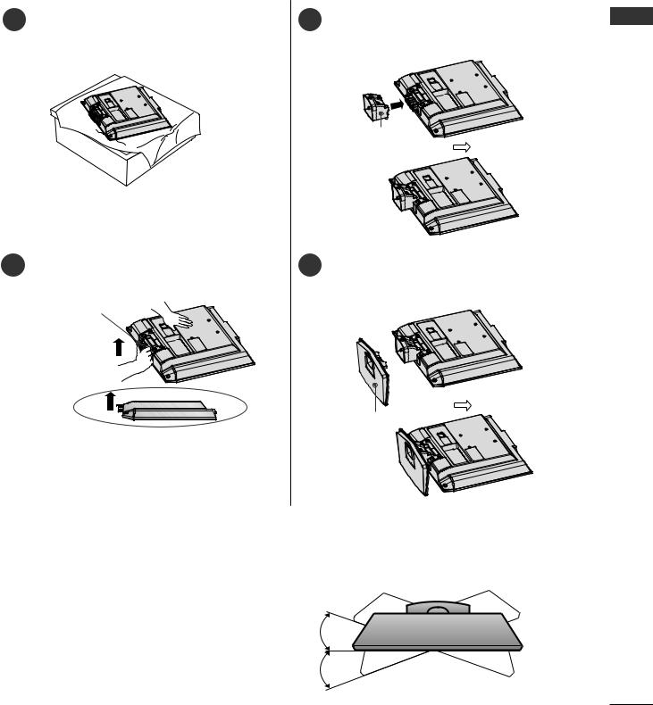
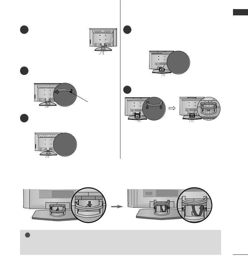
STAND INSTALLATION (Only 19/22LS4D*)
■ Image shown may differ from your TV.
1 |
Carefully place the TV screen side down on a |
3 Insert the Stand Body into the TV until clicking |
|
cushioned surface to protect the screen from |
sound. |
|
|
damage.
Stand Body
2 Hold the Hinge Body and bend it upward. |
4 Assemble the parts of the Stand Body with |
|
the Cover Base of the TV. |
Hinge Body |
|
Cover Base
PREPARATION
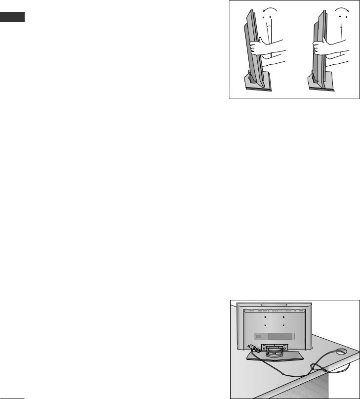
Swivel Stand
(Except for 19/22LS4D*, 50PG10**)
After installing the TV, you can adjust the TV manually to the left or right direction by 20 degrees to suit your viewing position.
11
Downloaded From TV-Manual.com Manuals

PREPARATION
DETACHING STAND (Only 19/22LS4D*)
■ Image shown may differ from your TV.
|
1 Place the tv with its front facing downward on a |
4 Hold the Stand Body and bend it upward. |
|
||
|
cushion or soft cloth. |
|
|
|
PREPARATION
2Pull the Cover Base backward during pressing a button on the Stand Body.
5Pull stand body to separate from the TV during pressing 2 latches.
3Hold the Cover Base and pull with shake it backward to separate from the Stand Body.
12
Downloaded From TV-Manual.com Manuals
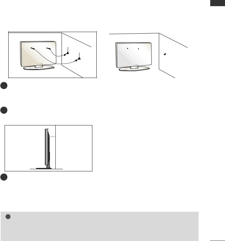
PLEASE SET IT UP CAREFULLY SO THE PRODUCT DOES NOT FALL OVER.
■ You should purchase necessary components to fix the TV to the wall on the market.
■ Position the TV close to the wall to avoid the possibility of it falling when pushed.
■ |
The instructions shown below are a safer way to set up the TV, which is to fix it to the wall, avoiding the |
PREPARATION |
|
|
possibility of it falling forwards if pulled. This will prevent the TV from falling forward and causing injury. This |
||
|
|
||
|
will also prevent the TV from damage. Ensure that children do not climb or hang from the TV. |
|
|
|
1 |
1 |
|
|
2 |
2 |
|
1Use the eye-bolts or TV brackets/bolts to fix the TV to the wall as shown in the picture. (If your TV has bolts in the eyebolts, loosen these bolts.)
* Insert the eye-bolts or TV brackets/bolts and tighten them securely in the upper holes.
2Secure the wall brackets with the bolts on the wall. Match the height of the bracket that is mounted on the wall.
3
3Use a sturdy rope to tie the TV. It is safer to tie the rope so it becomes horizontal between the wall and the TV.
! NOTE
GWhen moving the TV undo the cords first.
GUse a platform or cabinet strong and large enough to support the size and weight of the TV.
GTo use the TV safely make sure that the height of the bracket on the wall and on the TV is the same.
13
Downloaded From TV-Manual.com Manuals

PREPARATION
PREPARATION
BACK COVER FOR WIRE ARRANGEMENT
PLASMA TV Models
1Connect the cables as necessary.
To connect additional equipment, see the External Equipment Setup section.
2Install the CABLE MANAGEMENT CLIP as shown.
If your TV has the CABLE HOLDER, install it as shown and bundle the cables.
(Only 42/50PG10**) |
(Only 42/50PG30**) |
CABLE HOLDER |
CABLE MANAGEMENT CLIP
CABLE HOLDER
CABLE MANAGEMENT CLIP
How to remove the cable management clip
Hold the CABLE MANAGEMENT CLIP with both hands and pull it upward.
* For the 42PG10** model, press the center of the CABLE MANAGEMENT CLIP and then lift up it.
(Only 42/50PG10**) |
(Only 42/50PG30**) |
14
Downloaded From TV-Manual.com Manuals
LCD TV Models: 19/22/26/32/37/42LG30** 32/37/42/47/52LG50**
1 Connect the cables as necessary.
To connect additional equipment, see the External Equipment Setup section of the manual.
2Open the CABLE MANAGEMENT CLIP as shown and manage the cables.
CABLE MANAGEMENT CLIP |
3Fit the CABLE MANAGEMENT CLIP as shown.
LCD TV Models : 19/22LS4D*
1Connect the cables as necessary.
To connect additional equipment, see the External Equipment Setup section.
2 Install the CABLE MANAGEMENT CLIP as shown.
PREPARATION
How to remove the cable management clip (LCD TV Models : 19/22LS4D*)
First, press the cable management. Hold the CABLE MANAGEMENT CLIP with both hands and pull it upward.
! NOTE
G Do not use the CABLE MANAGEMENT CLIP to lift the TV.
- If the TV is dropped, you may be injured or the TV may be damaged.
15
Downloaded From TV-Manual.com Manuals
PREPARATION
POSITIONING YOUR DISPLAY (Only 19/22LG30**, 19/22LS4D*)
■Image shown may differ from your TV.
■Adjust the position of the panel in various ways for maximum comfort.
PREPARATION
• Tilt range
10~12
0 |
3 |
LOCATION (Only 19/22LG30**, 19/22LS4D*)
Position your TV so that no bright light or sunlight falls directly onto the screen. Care should be taken not to expose the tv to any unnecessary vibration, moisture, dust or heat. Also ensure that the TV is placed in a position to allow a free flow of air. Do not cover the ventilation openings on the back cover.
If you intend to mount the TV to a wall, attach VESA standard mounting interface (optional parts) to the back of the TV.
When you install the TV to use the wall mounting bracket (optional parts), fix it carefully so as not to drop.
KENSINGTON SECURITY SYSTEM (Only 19/22LG30**, 19/22LS4D*)
The TV is equipped with a Kensington Security System connector on the back panel. Connect the Kensington Security System cable as shown below.
For the detailed installation and use of the Kensington Security System, refer to the user’s guide provided with the Kensington Security System.
For further information, contact http://www.kensington.com, the internet homepage of the Kensington
company. Kensington sells security systems for expensive electronic equipment such as notebook PCs and LCD projectors.
NOTE
- The Kensington Security System is an optional accessory.
NOTES
a.If the TV feels cold to the touch, there may be a small “flicker” when when it is turned on.
This is normal, there is nothing wrong with TV.
b. Some minute dot defects may be visible on the screen, appearing as tiny red, green, or blue spots. However, they have no adverse effect on the monitor's performance.
c. Avoid touching the LCD screen or holding your finger(s) against it for long periods of time.
Doing so may produce some temporary distortion effects on the screen.
16
Downloaded From TV-Manual.com Manuals
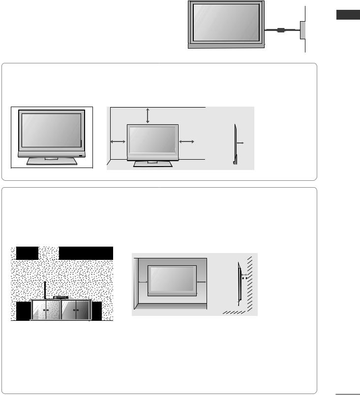
■The TV can be installed in various ways such as on a wall, or on a desktop etc.
■The TV is designed to be mounted horizontally.
EARTHING
Ensure that you connect the earth wire to prevent possible electric shock. If grounding methods are not possible, have a qualified electrician install a separate circuit breaker.
Do not try to earth the TV by connecting it to telephone wires, lightening rods or gas pipes.
DESKTOP PEDESTAL INSTALLATION
For adequate ventilation allow a clearance of 4” (10cm) all around the TV.
4 inches
4 inches |
|
|
|
4 inches |
4 inches |
|
|
|
|||
|
|
|
|
|
|
|
|
|
|
|
|
|
|
|
|
|
|
Power Supply
Circuit breaker
PREPARATION
WALL MOUNT: HORIZONTAL INSTALLATION
For adequate ventilation allow a clearance of 4” (10cm) all around the TV. Detailed installation instructions are available from your dealer, see the optional Tilt Wall Mounting Bracket Installation and Setup Guide.
 4 inches
4 inches
4 inches |
4 inches |
 4 inches
Not using the desk-type stand
(Except for 19/22LS4D*)
When installing the wall-mounted unit, use the |
|
|
|
protection cover for desk-type stand installation. |
|
|
|
Insert the PROTECTION COVER into the TV |
< PLASMA TV > |
< LCD TV > |
|
until clicking sound. |
|||
|
|
17
Downloaded From TV-Manual.com Manuals

PREPARATION
■ To prevent damage do not connect to the mains outlet until all connections are made between the devices.
ANTENNA CONNECTION
■For optimum picture quality, adjust antenna direction.
■An antenna cable and converter are not supplied.
PREPARATION
Wall |
Multi-family Dwellings/Apartments |
|
(Connect to wall antenna socket) |
||
Antenna |
||
|
||
Socket |
|
ANTENNA IN |
RF Coaxial Wire (75 ohm)
Outdoor
Antenna
(VHF, UHF) Single-family Dwellings /Houses
(Connect to wall jack for outdoor antenna)
UHF
Antenna |
ANTENNA IN |
|
Signal |
|
Amplifier |
|
VHF |
■In poor signal areas, to achieve better picture quality it may be necessary to install a signal amplifier to the antenna as shown above.
■If signal needs to be split for two TVs, use an antenna signal splitter for connection.
18
Downloaded From TV-Manual.com Manuals
EXTERNAL EQUIPMENT SETUP
■To avoid damaging any equipment, never plug in any power cords until you have finished connecting all equipment.
■This section on EXTERNAL EQUIPMENT SETUP mainly uses diagrams for the 22LS4D* models.
HD RECEIVER SETUP
■This TV can receive Digital RF/Cable signals without an external digital set-top box. However, if you do receive Digital signals from a digital set-top box or other digital external device, refer to the diagram as shown below.
Connecting with a component cable
1Connect the video outputs (Y, PB, PR) of the digital set top box to the COMPONENT IN VIDEO jacks on the TV.
2Connect the audio output of the digital set-top box to the COMPONENT IN AUDIO jacks on the TV.
3Turn on the digital set-top box.
(Refer to the owner’s manual for the digital set-top box.)
4Select Component input source using the INPUT button on the remote control.
Signal |
Component |
HDMI |
|
|
|
|
|
|
480i/576i |
Yes |
No |
480p/576p |
Yes |
Yes |
720p/1080i |
Yes |
Yes |
1080p |
Yes |
Yes |
|
|
|
|
|
|
|
COMPONENT IN |
|
||
|
VIDEO |
|
AUDIO |
|
Y |
PB |
PR |
L |
R |
12
Connecting a set-top box with an HDMI cable |
HDMI/DVI IN |
SETUP EQIPMENT EXTERNAL
Connect the HDMI output of the digital set-top box to the
1HDMI/DVI IN, HDMI/DVI IN 1, HDMI IN 2 or HDMI IN 3 jack on the TV.
2Turn on the digital set-top box.
(Refer to the owner’s manual for the digital set-top box.)
3Select HDMI/DVI, HDMI1, HDMI2 or HDMI3 input source using the INPUT button on the remote control.
1
19
Downloaded From TV-Manual.com Manuals
EXTERNAL EQUIPMENT SETUP
Connecting with a HDMI to DVI cable
|
|
1 |
Connect the digital set-top box to HDMI/DVI IN, |
|
EXTERNAL |
||||
2 |
HDMI/DVI IN 1(DVI) or HDMI/DVI IN 1 jack on |
|||
Connect the audio output of the digital set-top box to |
||||
|
|
|
the TV. |
|
EQIPMENT |
|
the AUDIO IN (RGB/DVI) jack on the TV. |
||
3 |
Turn on the digital set-top box. (Refer to the owner’s |
|||
|
|
|||
|
|
|
manual for the digital set-top box.) |
|
SETUP |
4 |
Select HDMI/DVI or HDMI 1 input source using the |
||
|
INPUT button on the remote control. |
|||
|
|
|
|
|
HDMI/DVI IN |
AUDIO IN |
||
|
(RGB/DVI) |
||
|
|
|
|
2
1
AUDIO
DVI-PC OUTPUT
DIGITAL AUDIO OUT SETUP
(Except for 19/22LS4D*)
-Sending the TV’s audio signal to external audio equipment via the Digital Audio Output (Optical) port.
1 Connect one end of an optical cable to the TV Digital Audio (Optical) Output port.
|
|
OPTICAL |
COMPONENT |
|
AUDIO IN |
IN |
AV |
||
(RGB/DVI) |
|
DIGITAL |
AV 1 |
|
|
|
AUDIO OUT |
|
|
DVI IN |
1 |
VIDEO |
|
|
|
|
|||
2Connect the other end of the optical cable to the digital audio (optical) input on the audio equipment.
3Set the “ TV Speaker option - Off ” in the AUDIO menu. (G p.78) Refer to the external audio equipment instruction manual for operation.
RGB IN
RS-232C IN
(CONTROL & SERVICE)
2
AUDIO
 CAUTION
GDo not look into the optical output port. Looking at the laser beam may damage your vision.
20
Downloaded From TV-Manual.com Manuals

DVD SETUP
When connecting with a component cable
1Connect the video outputs (Y, PB, PR) of the DVD to the COMPONENT IN VIDEO jacks on the TV.
2Connect the audio outputs of the DVD to the COMPONENT IN AUDIO jacks on the TV.
3 Turn on the DVD player, insert a DVD.
4Select Component input source using the INPUT button on the remote control.
5 Refer to the DVD player's manual for operating instructions.
Component Input ports
To achieve better picture quality, connect a DVD player to the component input ports as shown below.
Component ports on the TV |
Y |
PB |
PR |
|
|
|
|
|
|
|
|
|
Y |
PB |
PR |
Video output ports |
Y |
B-Y |
R-Y |
on DVD player |
Y |
Cb |
Cr |
|
Y |
Pb |
Pr |
|
|
|
|
Connecting with a Euro Scart cable
1Connect the Euro scart socket of the DVD to the AV1 Euro scart socket on the TV.
2Turn on the DVD player, insert a DVD.
3Select AV1 input source using the INPUT button on the remote control.
If connected to AV2 Euro scart socket, select AV2 input source.
4Refer to the DVD player's manual for operating instructions.
!NOTE
G Any Euro scart cable used must be signal shielded.
|
COMPONENT IN |
|
||
|
VIDEO |
|
AUDIO |
|
Y |
PB |
PR |
L |
R |
|
EXTERNAL |
1 |
SETUPEQIPMENT |
2 |
|
|
|
|
|
|
|
|
|
|
|
|
|
|
|
|
|
|
|
AV 1 |
AV 2 |
|
||
|
|
|
|
|
|
|
|
|
|
|
|
|
|
|
|
|
|
|
|
|
|
|
|
|
|
|
|
|
|
|
|
|
|
|
|
|
|
|
|
|
|
|
|
|
|
|
|
|
|
|
|
|
|
|
|
|
|
|
|
|
|
|
|
|
|
|
|
|
|
|
|
|
|
|
|
|
|
|
|
|
|
|
|
|
|
|
|
|
|
|
|
|
|
|
|
|
|
|
|
|
|
|
|
|
|
|
|
|
|
|
|
1
|
|
(R) AUDIO (L) |
|
|
|
|
|
|
|
|
|
|
AUDIO/ |
|
|
VIDEO |
|
|
|
|
21
Downloaded From TV-Manual.com Manuals

EXTERNAL EQUIPMENT SETUP
Connecting with a S-Video cable
(Except for 19/22LS4D*, 42/50PG10**)
|
|
1 |
Connect the S-VIDEO output of the DVD to the |
|
EXTERNAL |
S-VIDEO input on the TV. |
|||
|
||||
2 |
Connect the audio outputs of the DVD to the AUDIO |
|||
|
|
|||
EQIPMENT |
|
input jacks on the TV. |
||
3 |
Turn on the DVD player, insert a DVD. |
|||
|
|
|||
|
|
4 |
Select AV3 input source using the INPUT button on |
|
SETUP |
|
the remote control. |
||
5 |
Refer to the DVD player's manual for operating |
|||
instructions.
SLOTCARD
PCMCIA
HDMI 3IN
S-VIDEO R
AUDIO
L/MONO
IDEOV
AV IN 3
VIDEO |
S-VIDEO |
L |
R |
ANT IN |
|||||||
|
|
|
|
|
|
|
|
|
|
|
|
|
|
|
|
|
|
|
|
|
|
|
|
|
|
|
|
|
|
|
|
|
|
|
|
|
|
|
|
|
|
|
|
|
|
|
|
|
|
|
|
|
|
|
|
|
|
|
|
ANT OUT
12
Connecting the HDMI cable
1Connect the HDMI output of the DVD to the HDMI/DVI IN, HDMI/DVI IN 1, HDMI IN 2 or HDMI IN 3 jack on the TV.
2Select HDMI/DVI, HDMI1, HDMI2 or HDMI3 input source using the INPUT button on the remote control.
3Refer to the DVD player's manual for operating instructions.
! NOTE
G The TV can receive video and audio signals simultaneously when using a HDMI cable.
G If the DVD does not support Auto HDMI, you must set the output resolution appropriately.
22
HDMI/DVI IN
1
Downloaded From TV-Manual.com Manuals

VCR SETUP
■To avoid picture noise (interference), allow adequate distance between the VCR and TV.
■If 4:3 picture format is used for an extended period the fixed images on the sides of the screen may remain visible.
When connecting with a RF Cable
ANTENNA IN |
ANT OUT S-VIDEO VIDEO |
L |
R |
|
|
1 |
|
|
|
|
ANT IN |
OUTPUT |
|
|
|
SWITCH |
|
|
|
|
|
|
|
|
Wall Jack
2
Antenna
SETUP EQIPMENT EXTERNAL
1Connect the ANT OUT socket of the VCR to the ANTENNA IN socket on the TV.
2Connect the antenna cable to the ANT IN socket of the VCR.
3Press the PLAY button on the VCR and match the appropriate channel between the TV and VCR for viewing.
23
Downloaded From TV-Manual.com Manuals

EXTERNAL EQUIPMENT SETUP
Connecting with a Euro Scart cable
|
|
1 |
Connect the Euro scart socket of the VCR to the AV1 |
|
|
|
|||
|
|
|
Euro scart socket on the TV. |
|
EXTERNAL |
|
|||
2 |
Insert a video tape into the VCR and press PLAY on |
|||
|
|
|||
EQIPMENT |
|
the VCR. (Refer to the VCR owner’s manual.) |
||
4 |
If connected to AV2 Euro scart socket, select AV2 |
|||
|
|
3 |
Select AV1 input source using the INPUT button on |
|
|
|
|
the remote control. |
|
SETUP |
|
input source. |
||
|
|
|||
|
|
|||
! NOTE
G Any Euro scart cable used must be signal shielded.
|
|
AV 1 |
AV 2 |
||
|
|
|
|
|
|
|
|
|
|
|
|
|
|
|
|
|
|
|
|
|
|
|
|
|
|
|
|
|
|
|
|
|
|
|
|
|
|
|
|
|
|
|
|
|
|
|
|
|
|
|
|
|
|
|
|
|
|
|
|
|
|
|
|
|
|
|
|
|
|
|
|
|
|
|
|
|
|
|
|
|
|
|
|
|
|
|
|
|
|
1
|
|
(R) AUDIO (L) |
|
|
|
|
|
|
|
|
|
|
AUDIO/ |
|
|
VIDEO |
|
|
|
|
Connecting with a RCA cable
(Except for 42/50PG10**)
1Connect the AUDIO/VIDEO jacks between TV and VCR. Match the jack colours (Video = yellow, Audio Left = white, and Audio Right = red)
2Insert a video tape into the VCR and press PLAY on the VCR. (Refer to the VCR owner’s manual.)
3Select AV3 input source using the INPUT button on the remote control.
!NOTE
G If you have a mono VCR, connect the audio cable from the VCR to the AUDIO L/MONO jack of the TV.
24
SLOTCARD
PCMCIA
HDMI 3IN
S-VIDEO
R
VIDEO L/MONO AUDIO
AV IN 3
L |
R |
VIDEO S-VIDEO ANT IN |
||||
|
|
|
|
|
|
|
|
|
|
|
|
|
|
ANT OUT
Downloaded From TV-Manual.com Manuals

Connecting with a S-Video cable
(Except for 19/22LS4D*, 42/50PG10**)
1Connect the S-VIDEO output of the VCR to the S - VIDEO input on the TV. The picture quality is improved; compared to normal composite (RCA cable) input.
2Connect the audio outputs of the VCR to the AUDIO input jacks on the TV.
3Insert a video tape into the VCR and press PLAY on the VCR. (Refer to the VCR owner’s manual.)
4Select AV3 input source using the INPUT button on the remote control.
!NOTE
GIf both S-VIDEO and VIDEO sockets have been connected to the S-VHS VCR simultaneously, only the S-VIDEO can be received.
SLOTCARD
PCMCIA
HDMI 3IN
S-VIDEO R
UDIOA
MONO/L
IDEOV
AV IN 3
S-VIDEO VIDEO |
L |
R |
ANT IN |
||||||||
|
|
|
|
|
|
|
|
|
|
|
|
|
|
|
|
|
|
|
|
|
|
|
|
|
|
|
|
|
|
|
|
|
|
|
|
OUTPUT |
ANT OUT |
SWITCH |
|
12
SETUP EQIPMENT EXTERNAL
OTHER A/V SOURCE SETUP
(Except for 19/22LS4D*, 42/50PG10**)
1Connect the AUDIO/VIDEO jacks between TV and external equipment. Match the jack colours. (Video = yellow, Audio Left = white, and Audio Right = red)
2Select AV3 input source using the INPUT button on the remote control.
3Operate the corresponding external equipment. Refer to external equipment operating guide.
SLOTCARD
PCMCIA
HDMI 3IN
S-VIDEO R
VIDEO L/MONO AUDIO
AV IN 3
Camcorder
Video Game Set
VIDEO L R
1
25
Downloaded From TV-Manual.com Manuals

EXTERNAL EQUIPMENT SETUP
INSERTION OF CI MODULE
-To view the encrypted (pay) services in digital TV mode.
-This feature is not available in all countries.
Insert the CI Module to PCMCIA (Personal Computer
EXTERNAL |
1 |
For further information, see p.52. |
|
|
Memory Card International Association) CARD SLOT |
|
|
of TV as shown. |
SETUP EQIPMENT |
|
|
|
|
PCMCIA
CARD SLOT
1
TV
PC SETUP
This TV provides Plug and Play capability, meaning that the PC adjusts automatically to the TV's settings.
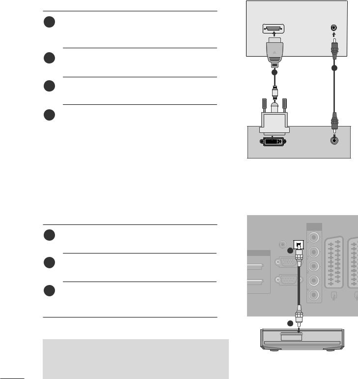
Connecting with a D-sub 15 pin cable
RGB (PC) IN |
AUDIO IN |
|
(RGB/DVI) |
1 |
Connect the RGB output of the PC to the RGB IN |
|
|
(PC) jack on the TV. |
|
2 |
Connect the PC audio output to the AUDIO IN |
|
|
(RGB/DVI) jack on the TV. |
|
3 |
Turn on the PC and the TV |
2 |
|
1 |
|
4 |
Select RGB input source using the INPUT button on |
|
|
the remote control. |
|
|
|
|
|
RGB OUTPUT |
AUDIO |
||
|
|
|
|
|
|
|
|
26
Downloaded From TV-Manual.com Manuals

Connecting with a HDMI to DVI cable
1Connect the DVI output of the PC to the HDMI/DVI IN, HDMI/DVI IN 1(DVI) or HDMI/DVI IN 1 jack on the TV.
2Connect the PC audio output to the AUDIO IN (RGB/DVI) jack on the TV.
3Turn on the PC and the TV.
4Select HDMI/DVI or HDMI 1 input source using the INPUT button on the remote control.
!NOTE
HDMI/DVI IN |
AUDIO IN |
||
|
(RGB/DVI) |
||
|
|
|
|
2
1
AUDIO
DVI-PC OUTPUT
G To enjoy vivid picture and sound, connect a PC to the TV.
G Avoid keeping a fixed image on the TV’s screen for prolonged periods of time. The fixed image may become permanently imprinted on the screen; use a screen saver when possible.
G Connect the PC to the RGB (PC) or HDMI IN (or HDMI/DVI IN) port of the TV; change the resolution.
G There may be interference relating to resolution, vertical pattern, contrast or brightness in PC mode. Change the PC mode to another resolution or change the refresh rate to another rate or adjust the brightness and contrast on the menu until the picture is clear. If the refresh rate of the PC graphic card can not be changed, change the PC graphic card or consult the manufacturer of the PC graphic card.
G The synchronization input waveform for Horizontal and Vertical frequencies are separate.
G Connect the signal cable from the monitor output port of the PC to the RGB (PC) port of the TV or the signal cable from the HDMI output port of the PC to the HDMI IN (or HDMI/DVI IN) port on the TV.
G Connect the audio cable from the PC to the Audio input on the TV. (Audio cables are not included with the TV).
G If using a sound card, adjust PC sound as required. G This TV uses a VESA Plug and Play Solution. The TV provides EDID data to the PC system with a DDC protocol. The PC adjusts automatically when
using this TV.
G DDC protocol is preset for RGB (Analog RGB), HDMI (Digital RGB) mode.
G If required, adjust the settings for Plug and Play functionality.
G If the graphic card on the PC does not output analogue and digital RGB simultaneously, connect only one of either RGB or HDMI IN (or HDMI/DVI IN) to display the PC output on the TV.
G If the graphic card on the PC does output analogue and digital RGB simultaneously, switch the TV to either RGB or HDMI; (the other mode is set to Plug and Play automatically by the TV.)
G DOS mode may not work depending on the video card if you use a HDMI to DVI cable.
G If you use too long an RGB-PC cable, there may be interference on the screen. We recommend using under 5m of cable. This provides the best picture quality.
SETUP EQIPMENT EXTERNAL
27
Downloaded From TV-Manual.com Manuals
EXTERNAL EQUIPMENT SETUP
SETUP EQIPMENT EXTERNAL
Supported Display Resolution (Only 19/22LS4D*)
RGB[PC], HDMI[PC] mode |
|
|
HDMI[DTV] mode |
|
||
|
|
|
|
|
|
|
Resolution |
Horizontal |
Vertical |
|
Resolution |
Horizontal |
Vertical |
Frequency(kHz) |
Frequency(Hz) |
|
Frequency(kHz) |
Frequency(Hz) |
||
|
|
|
||||
|
|
|
|
|
|
|
720x400 |
31.469 |
70.08 |
|
720x480 |
31.469 |
59.94 |
|
31.469 |
59.94 |
|
31.5 |
60 |
|
640x480 |
|
|
||||
37.879 |
60.31 |
|
720x576 |
31.25 |
50 |
|
|
|
|||||
800x600 |
37.879 |
60.31 |
|
|
37.500 |
50 |
48.363 |
60.00 |
|
1280x720 |
44.96 |
59.94 |
|
|
|
|||||
1024x768 |
48.363 |
60.00 |
|
|
45 |
60 |
47.776 |
59.87 |
|
|
33.72 |
59.94 |
|
|
|
|
||||
1280x768 |
47.69 |
59.99 |
|
|
33.75 |
60 |
1280x1024 |
63.981 |
60.02 |
|
|
28.125 |
50.00 |
47.920 |
59.995 |
|
|
26.97 |
23.97 |
|
|
|
|
||||
1360x768 |
47.65 |
59.93 |
|
1920x1080 |
27 |
24 |
1366x768 |
47.13 |
59.65 |
|
33.716 |
29.976 |
|
|
|
|||||
1440x900 |
55.5 |
59.90 |
|
|
33.75 |
30.00 |
1400x1050 |
67.744 |
59.948 |
|
|
56.250 |
50 |
1680x1050 |
65.16 |
59.94 |
|
|
67.43 |
59.94 |
1920x1080 |
67.43 |
59.94 |
|
|
67.5 |
60 |
67.5 |
60 |
|
|
|
|
|
|
|
|
|
|
||
|
|
|
|
|
|
|
! NOTE
G It is not supported to 1680x1050 in RGB[PC] mode.
G 19LS4D* is supported to 1440x900, 1400x1050 and 1680x1050 in RGB/HDMI[PC] mode.
G 19/22LS4D* is supported to 640x480 59.64Hz, 800x600 60.31Hz, 1024x768 60Hz, 180x768 59.99Hz and 1280x1024 60.02Hz in RGB[PC] mode.
G 19/22LS4D* is supported to 640x480 60.31Hz, 800x600 60Hz, 1024x768 59.87Hz, 180x768 59.995Hz and 1280x1024 59.995Hz in HDMI[PC] mode.
G 19LG30** is supported to 1440x900 in RGB/HDMI[PC] mode.
G 22LG30** is supported to 1400x1050 and 1680x1050 in RGB/HDMI[PC] mode.
G 37/42/47/52LG50** is supported to 1280x1024 and 1920x1080 in RGB/HDMI[PC] mode.
28
Downloaded From TV-Manual.com Manuals
Loading...