


 Loading...
Owner's Manual
IPS LED MONITOR LED LCD MONITOR (LED MONITOR*)
*LG LED Monitors are LCD Monitors with LED Backlighting.
Please read this manual carefully before operating your set and retain it for future reference.
IPS LED(LED LCD) MONITOR MODEL
16M38A 
 19M38A
 20M38A
 22M38A
 24M38A
 27MP38VQ 16M38I
 19M38D
 20M38D
 22M38D
 24M38D
 27MP38HQ
20M38H 
 22M38H
 24M38H
www.lg.com

<![endif]>ENGLISH
2 TABLE OF CONTENTS
CONTENTS
3 |
LICENSE |
28 |
TROUBLESHOOTING |
|
4 |
|
|
|
|
ASSEMBLING AND PREPAR- |
|
30 |
SPECIFICATIONS |
|
|
ING |
42 |
Preset Modes (Resolution) |
|
|
|
|||
4Unpacking
6Parts and buttons
7 Moving and Lifting the Monitor
8Setting up the Monitor set
8- Attaching the Stand Base 9 - Detaching the Stand Base 11 - Mounting on a table
11 - Using the cable holder
13 - Mounting on a wall
43Indicator
44PROPER POSTURE
44 Proper posture for using the Monitor set.
14 USING THE MONITOR SET
14Connecting to a PC
14- D-SUB connection
14- DVI-D connection
15- HDMI connection
15Connecting to AV Devices
15- HDMI connection
16Connecting to External Devices
16- Peripheral device connection
17CUSTOMIZING SETTINGS
18Customizing Settings
18 - Menu Settings
20-Picture
21-Color
22-Display
22-Audio
23-Others
24READER Setting
25FUNC. Setting
25-SMART ENERGY SAVING
26-Picture Mode
27-Color Weakness

LICENSE 3
20M38H 
 22M38H
 24M38H
 27MP38VQ
 27MP38HQ
LICENSE
Each model has different licenses. Visit www.lg.com for more information on the license.
The terms HDMI and HDMI High-Definition Multimedia Interface, and the HDMI logo are trademarks or registered trademarks of HDMI Licensing LLC in the United States and other countries.
<![endif]>ENGLISH
The following content is only applied to the monitor which is sold in Europe market and which needs to meet the ErP Directive:
*This monitor is set to be turned off automatically in 4 hours after you turned on display if there is no adjustment to display.
*To make this setting be disabled, change the option to ‘Off’ in OSD menu of “Automatic Standby”.

<![endif]>ENGLISH
4 ASSEMBLING AND PREPARING
ASSEMBLING AND PREPARING
Unpacking
Check your product box for the following items. If there are any missing accessories, contact the local dealer where you purchased your product. The illustrations in this manual may differ from the actual product and accessories.
CD(Owner's Manual) / |
D-SUB Cable |
|
( This cable is not included in all |
||
Card |
||
countries. ) |
||
|
Power Cord |
AC-DC Adapter |
( Depending on the country )
Stand Body |
Stand Base |
or
AC-DC Adapter
( Depending on the country )
DVI-D Cable
( This cable is not included in all countries. )
HDMI Cable
Stand Body |
Stand Base |
( This cable is not included in all countries. )
Stand Body |
Two Screws |
Stand Base |
||
|
|
|
|
|
|
|
|
|
|
ASSEMBLING AND PREPARING 5
 CAUTION
yyDo not use any unapproved accessories to ensure the safety and product life span.
yyAny damages or injuries by using unapproved accessories are not covered by the warranty.
 NOTE
NOTE
yyThe accessories supplied with your product may vary depending on the model.
yyProduct specifications or contents in this manual may be changed without prior notice due to upgrade of product functions.
<![endif]>ENGLISH

6 ASSEMBLING AND PREPARING
Parts and buttons
<![if ! IE]><![endif]>ENGLISH
Power Indicator yyLightingOn:Turnedon yyLightingOff: Turned off

 (Power Button)
Button (See p.17)
Connection panel (See p.14~16)
|
ASSEMBLING AND PREPARING 7 |
|||
|
|
|
|
|
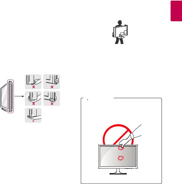
Moving and Lifting the Monitor |
yyWhen holding the monitor, the screen should |
|||
|
||||
When moving or lifting the monitor, follow these |
face away from you to prevent it being |
|||
instructions to prevent the monitor from being |
scratched. |
|||
scratched or damaged and to ensure safe trans- |
|
|
|
|
portation regardless of its shape or size. |
|
|
|
|
|
|
|
|
|
yyIt is advisable to place the monitor in the |
|
|
|
|
original box or packing material before at- |
|
|
|
|
tempting to move it. |
|
|
|
|
yyBefore moving or lifting the monitor, discon- |
|
|
|
|
nect the power cord and all cables. |
|
|
|
|
yyHold the top and bottom of the monitor frame |
yyWhen moving the monitor, avoid any strong |
|||
firmly. Do not hold the panel itself. |
shock or vibrations to the product. |
|||
|
yyWhen moving the monitor, keep it upright, |
|||
|
never turn the monitor on its side or tilt it |
|||
|
sideways. |
|||
 CAUTION
yyAs far as possible, avoid touching the monitor screen. This may result in damage to the screen or some of the pixels used to create images.
<![endif]>ENGLISH
<![endif]>ENGLISH
8 ASSEMBLING AND PREPARING
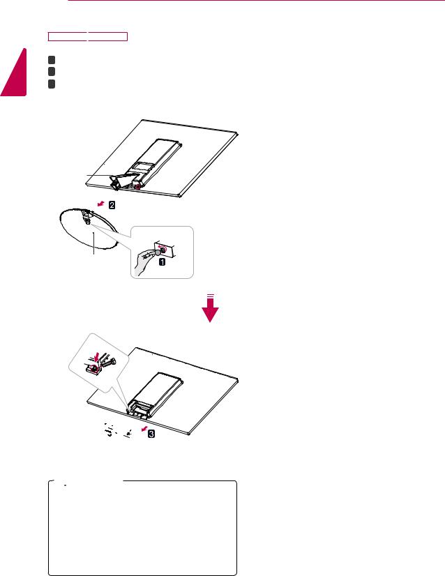
Setting up the Monitor set
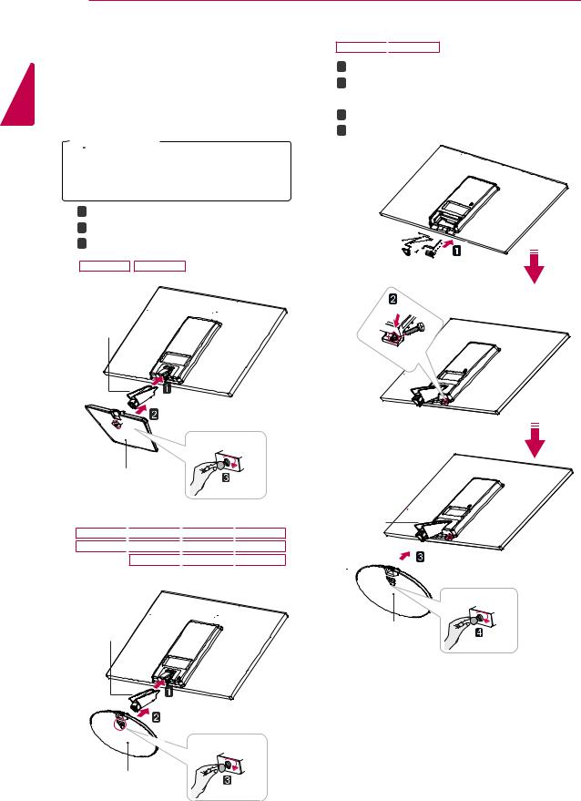
Attaching the Stand Base
1Place the Monitor set with the screen side down on a flat and cushioned surface.
 CAUTION
Lay a foam mat or soft protective cloth on the surface to protect the screen from damage.
21 Attach the Stand Body to the monitor set.
2 Attach the Stand Base.
3 Tighten the screw to the right with a coin.
16M38A 16M38I
Stand Body
Stand Base
19M38A 
 20M38A
 22M38A
 24M38A 19M38D
 20M38D
 22M38D
 24M38D 20M38H
 22M38H
 24M38H
27MP38VQ
 27MP38HQ
1 Attach the Stand Body to the monitor set.
2Use two screws to fix the Stand Body and monitor set.
3 Attach the Stand Base.
4 Tighten the screw to the right with a coin.
Stand Body 

Stand Body
Stand Body |
Stand Base |
Stand Base
ASSEMBLING AND PREPARING 9
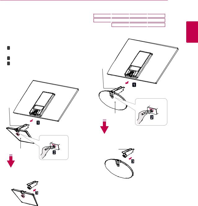
Detaching the Stand Base
1Place the Monitor set with the screen side down on a flat and cushioned surface.
21 Pull out the Stand Body and Stand Base from the monitor set.
2 |
Turn the screw to the left with a coin. |
|||
3 |
Pull out the Stand Base. |
|||
|
|
|
|
|
|
16M38A |
16M38I |
||
19M38A 
 20M38A
 22M38A
 24M38A 19M38D
 20M38D
 22M38D
 24M38D 20M38H
 22M38H
 24M38H
Stand Body
Stand Body
Stand Base
Stand Base |
Stand Body |
 Stand Base
Stand Body 
 Stand Base
<![endif]>ENGLISH
10 ASSEMBLING AND PREPARING
<![endif]>ENGLISH
27MP38VQ
 27MP38HQ
1 Turn the screw to the left with a coin.
2 Pull out the Stand Base from the Stand Body.
3Remove two screws and pull out the Stand Body from the monitor set.
Stand Body
Stand Base
Stand Body

 CAUTION
yyThis illustration depicts the general model of connection. Your monitor may differ from the items shown in the picture.
yyDo not carry the product upside down holding only the stand base. The product may fall and get damaged or injure your foot.
|
ASSEMBLING AND PREPARING 11 |
|
|
|
|
Mounting on a table |
3 Press (Power) button on the bottom switch |
|
|
panel to turn the power on. |
|
1 Lift and tilt the Monitor set into its upright |
|
|
position on a table. |
|
|
Leave a 10 cm (minimum) space from the wall |
|
|
for proper ventilation. |
CAUTION |
|
|
||
10 cm 
10 cm
10 cm
10 cm
Unplug the power cord before moving the Monitor to another location. Otherwise electric shock may occur.
Using the cable holder
<![endif]>ENGLISH
2 Connect the AC-DC Adapter and Power Cord
to a wall outlet.
Cable holder
or
<![endif]>ENGLISH
12 ASSEMBLING AND PREPARING
WARNING |
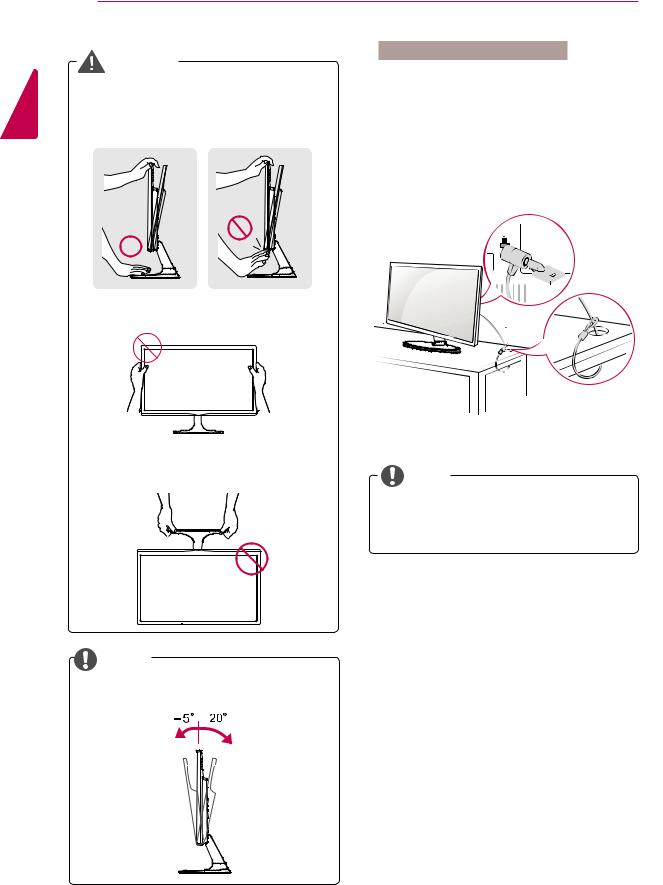
Using the Kensington security system |
|
The Kensington security system connector is |
||
When you adjust the angle, do not hold the |
||
located at the back of the Monitor set. For more |
||
bottom of the Monitor set frame as shown on |
information of installation and using, refer to the |
|
the |
manual supplied with the Kensington security |
|
|
system or visit http://www.kensington.com. |
|
|
Connect the Kensington security system cable |
|
|
between the Monitor set and a table. |
Do
Do not hold this set like below picture.Monitor
screen can detach from stand base and injure NOTE your body.
The Kensington security system is optional.
You can obtain it from most electronics stores.
NOTE
+20 to -5 degrees up or down to adjust the angle of the Monitor set to suit your view.
Front  Rear
Rear
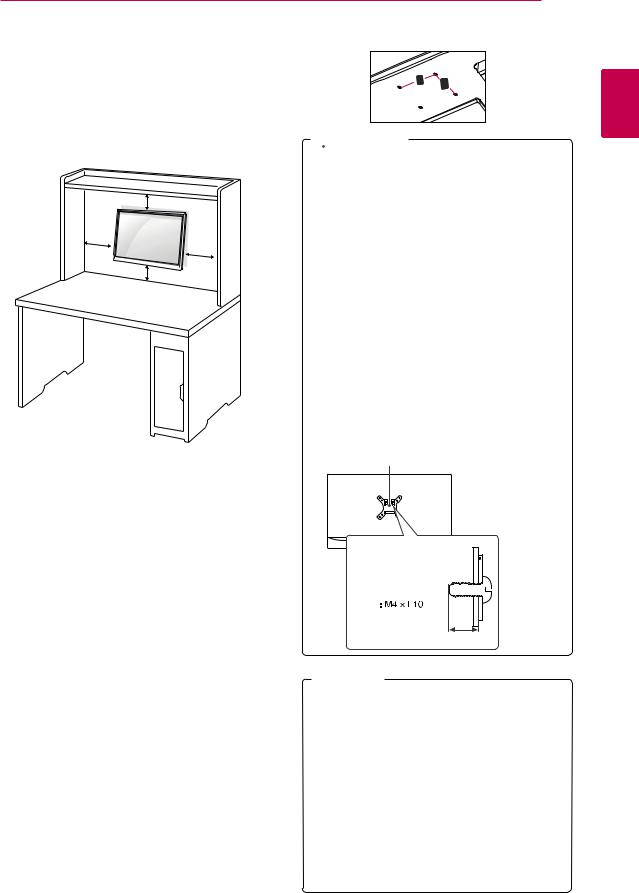
Mounting on a wall
For proper ventilation, allow a clearance of 10 cm on each side and from the wall. Detailed instructions are available from your dealer, see the optional Tilt Wall Mounting Bracket Installation and Setup Guide.
10 cm
10 cm
10 cm
10 cm
If you intend to mount the Monitor set to a wall, attach Wall mounting interface (optional parts) to the back of the set.
When you install the Monitor set using a wall mounting interface (optional parts), attach it carefully so it will not drop.
1 If you use screw longer than standard, the monitor might be damaged internally.
2 If you use improper screw, the product might be damaged and drop from mounted position.
In this case, LG Electronics is not responsible for it.
|
Model |
|
|
|
|
|
|
|
|
|
|
16M38A |
|
19M38A |
|
20M38A |
22M38A |
||||||
|
|
|
|
|
|
|
|
|
|
|
|
|
|
16M38I |
|
19M38D |
|
20M38D |
22M38D |
||||
|
|
|
|
|
|
|
|
|
|
|
|
|
|
|
|
|
|
|
|
|
20M38H |
22M38H |
|
|
|
|
|
|
|
|
|
|
|
|
|
|
Wall Mount (A |
|
75 x 75 |
|
|
|
|
|
|||
|
x B) |
|
|
|
|
|
|
|
|
|
|
|
Standard |
|
M4 |
|
|
|
|
|
|||
|
screw |
|
|
|
|
|
|
|
|
|
|
|
Number of |
4 |
|
|
|
|
|
|
|
||
|
screws |
|
|
|
|
|
|
|
|
|
|
|
|
|
|
|
|
|
|
|
|||
|
Model |
|
|
24M38A |
27MP38VQ |
24M38H |
|
|
|||
|
|
|
|
|
|
|
|
|
|||
|
|
|
|
24M38D |
27MP38HQ |
|
|
|
|||
|
|
|
|
|
|
|
|
|
|
|
|
|
Wall Mount (A |
100 x 100 |
|
|
|
|
|
||||
|
x B) |
|
|
|
|
|
|
|
|
|
|
|
Standard |
|
M4 |
|
|
|
|
|
|||
|
screw |
|
|
|
|
|
|
|
|
|
|
|
Number of |
|
4 |
|
|
|
|
|
|
|
|
|
screws |
|
|
|
|
|
|
|
|
|
|
ASSEMBLING AND PREPARING 13
yyWall Mount (A x B)
A |
B |
|
 CAUTION
yyDisconnect the power cord first, and then move or install the Monitor set. Otherwise electric shock may occur.
yyIf you install the Monitor set on a ceiling or slanted wall, it may fall and result in severe injury.
yyUse only an authorized LG wall mount and contact the local dealer or qualified personnel.
yyDo not over tighten the screws as this may cause damage to the Monitor set and void your warranty.
yyUse only screws and wall mounts that meet the VESA standard. Any damages or injuries by misuse or using an improper accessory are not covered by the warranty.
yyScrew length from outer surface of back cover should be under 8mm.
Wall mount Pad
 Back Cover
Wall mount Pad 
Back Cover 
Standard screw

Max.8mm
 NOTE
NOTE
yyUse the screws that are listed on the VESA standard screw specifications.
yyThe wall mount kit will include an installation manual and necessary parts.
yyThe wall mount bracket is optional. You can obtain additional accessories from your local dealer.
yyThe length of screws may differ depending on the wall mount. Be sure to use the proper length.
yyFor more information, refer to the instructions supplied with the wall mount.
<![endif]>ENGLISH
<![endif]>ENGLISH
14 USING THE MONITOR SET
USING THE MONITOR SET
Connecting to a PC
yyYour Monitor set supports Plug & Play*.
*Plug & Play: A PC recognizes a connected device that users connect to a PC and turn on, without device configuration or user intervention.
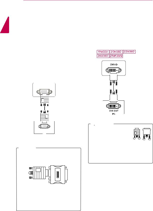
DVI-D connection
Transmits a digital video signal from your PC to the Monitor set. Connect the PC and the Monitor set with a DVI cable as shown in the following illustrations.
D-SUB connection
Transmits analog video from your PC to the Monitor set. Connect the PC and the Monitor set with the supplied D-sub 15 pin signal cable as shown in the following illustrations.
D-SUB
RGB OUT
PC
 NOTE
NOTE
yyWhen using a D-Sub signal input cable connector for Macintosh
yyMac adapter
For Apple Macintosh use, a separate plug adapter is needed to change the 15 pin high density (3 row) D-SUB VGA connector on the supplied cable to a 15 pin 2 row connector.
 CAUTION
yyConnect the signal input cable and tighten it by turning the
screws clockwise. yyDo not press the screen with
your finger for a long time as this may result in temporary distortion on the screen.
yyAvoid displaying a fixed image on the screen for a long period of time to prevent image burn. Use a screensaver if possible.
Loading...