


19 9L G3 30
Table of contents
 Loading...
LG Electronics 19 9L G3 30, 19 9L S4 4D, 22 2L G3 30, 22 2L S4 4D, 26 6L G3 30 User Manual
...
Please read this manual carefully before operating
your TV.
Retain it for future reference.
Record model number and serial number of the TV.
Refer to the label on the back cover and quote this
information.
To your dealer when requiring service.
This feature is not available for all models.
(Except for 19/22LS4D*)
LCD TV
OWNER’S MANUAL
LCD TV MODELS
1199LLSS44DD
**
2222LLSS44DD
**
1199LLGG3300
****
2222LLGG3300
****
2266LLGG3300
****
3322LLGG3300
****
3377LLGG3300
****
4422LLGG3300
****
3322LLGG5500
****
3377LLGG5500
****
44
22LLGG5500
****
4477LLGG5500
****
5522LLGG5500
****
PLASMA TV MODELS
4422 PPGG 1100
****
5500 PPGG 1100
****
4422 PPGG 2200
****
5500 PPGG 2200
****
4422 PPGG 3300
****
5500 PPGG 3300
****
6600 PPGG 3300
****
Trade Mark of the DVB Digital Video
Broadcasting Project (1991 to 1996)
ENGLISH
PLASMA TV
IIDD NN uummbbeerr((ss ))::
5499: 22LS4D-ZD 5507: 19LS4D-ZD
5107: 42PG1000-ZA 5106: 50PG1000-ZA
5107: 42PG2000-ZA 5106: 50PG2000-ZA
5109: 42PG3000-ZA 5108: 50PG3000-ZA
5498: 60PG3000-ZA
5088: 19LG3000-ZA 5090: 22LG3000-ZA
5080: 26LG3000-ZA 5089: 32LG3000-ZA
5087: 37LG3000-ZA 5086: 42LG3000-ZA
5085: 32LG5000-ZA 5084: 37LG5000-ZA
5083: 42LG5000-ZA 5082: 47LG5000-ZA
5081: 52LG5000-ZA 5385: 52LG5010-ZD
5386: 47LG5010-ZD 5387: 42LG5010-ZD
5388: 37LG5010-ZD 5389: 32LG5010-ZD
5390: 52LG5020-ZB 5391: 47LG5020-ZB
5392: 42LG5020-ZB 5393: 37LG5020-ZB
5394: 32LG5020-ZB 5395: 52LG5030-ZE
5396: 47LG5030-ZE 5397: 42LG5030-ZE
5398: 37LG5030-ZE 5399: 32LG5030-ZE
Downloaded From TV-Manual.com Manuals

Downloaded From TV-Manual.com Manuals
1
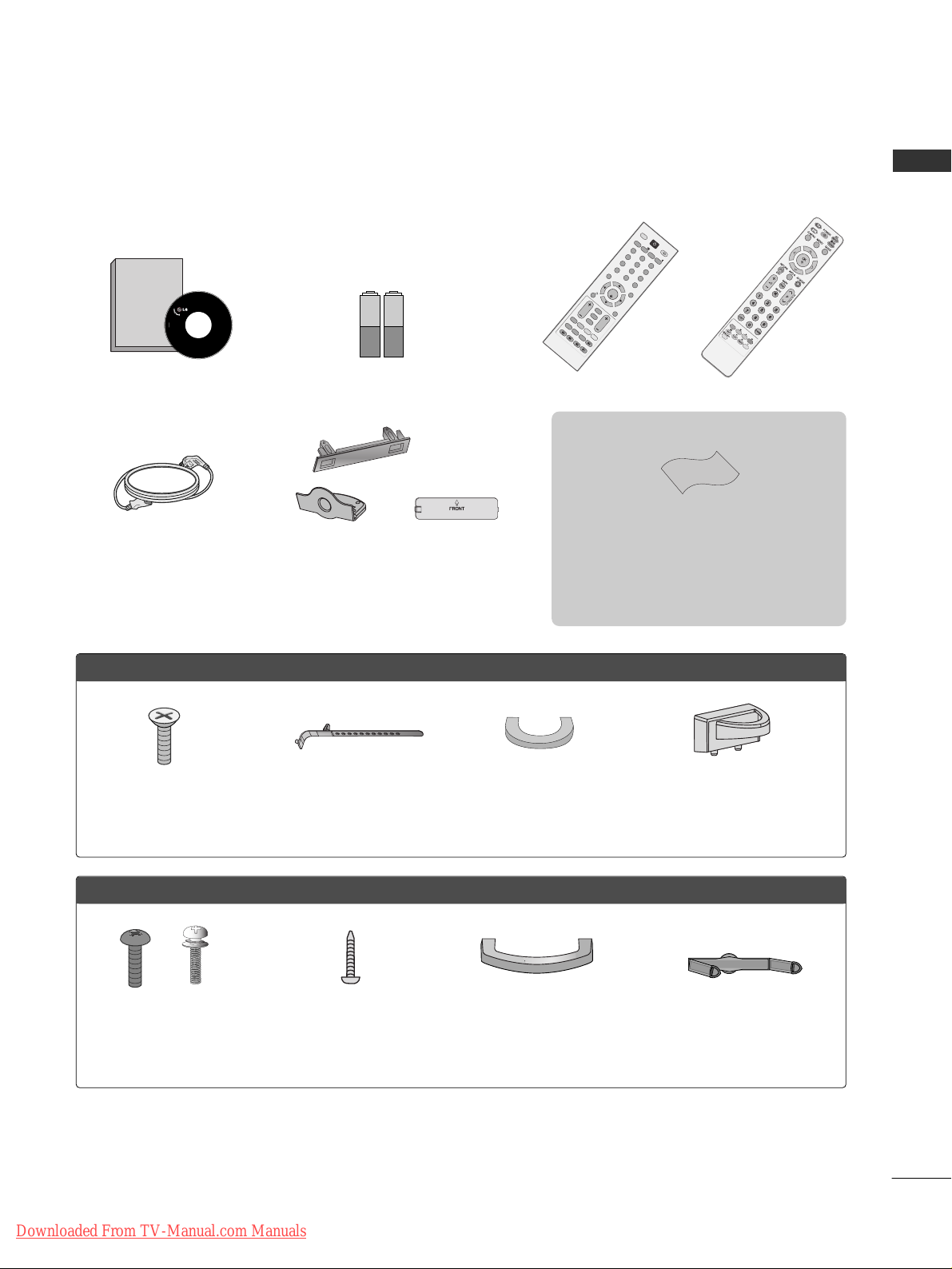
ACCESSORIES
ACCESSORIES
Ensure that the following accessories are included with your TV. If an accessory is missing, please contact the
dealer where you purchased the TV.
■
Image shown may differ from your TV.
Owner’s Manual Batteries Remote Control
or
Power Cord
Owner's
Manual
Owner’s manual
O
K
M
E
N
U
A
V
M
O
D
E
G
U
I
D
E
R
A
T
I
O
123
456
789
0
Q.VIEW
L
IS
T
T
V
I
N
P
U
T
D/A
P
O
W
E
R
V
O
L
P
R
IN
D
E
X
S
L
E
E
P
H
O
L
D
R
E
V
E
A
L
S
U
B
T
IT
L
E
UPDATE
I
/
I
I
M
U
T
E
T
E
X
T
R
E
T
U
R
N
E
X
IT
F
A
V
T
IM
E
I
N
F
O
i
TV/RADIO
*
?
R
A
T
I
O
PPLLAASSMMAA TTVV mmooddeellss
Protection Cover
(Except for 19/22LS4D*)
Polishing Cloth
Polishing cloth for use on the screen.
Lightly wipe any stains or fingerprints on the surface
of the TV with the polishing cloth.
Do not use excessive force. This may cause scratching
or discolouration.
Bolts for stand assembly
(Refer to p.11)
(Only 42PG10
*
*
, 42PG20
*
*
,
42PG30
*
*
)
x 4
Cable management clip
(Only 19/22LS4D*)
Cable management clip
(Only 19/22LG30**)
LLCCDD TTVV mmooddeellss
Bolts for stand assembly
(Refer to p.10)
(Only 32/37/42LG50**,
26/32/37/42LG30**)
1-screw for stand fixing
(Refer to p.5)
(Only 26/32/42LG30**,
32/42LG50**)
x 4 x 4
This feature is not available for all models.
Cable Holder
(42PG10**, 42PG20**,
42PG30**: 1EA, 50PG10**,
50PG20**, 50/60PG30**: 2EA)
Cable management clip
(Only 42/50PG10**)
Cable management clip
(Only 42/50PG20**,
42/50/60PG30**)
or
Downloaded From TV-Manual.com Manuals

2
CONTENTS
CONTENTS
ACCESSORIES
. . . . . . . . . . . . . . . . . . . . . . . . . . . . . . . . . . . . . . . . . . . . .
1
PREPARATION
Front Panel Controls . . . . . . . . . . . . . . . . . . . . . . . . 4
Back Panel Information . . . . . . . . . . . . . . . . . . . . . . 7
Stand Installation . . . . . . . . . . . . . . . . . . . . . . . . . . . 10
Detaching Stand . . . . . . . . . . . . . . . . . . . . . . . . . . . 13
Please set it up carefully so the product
does not fall over . . . . . . . . . . . . . . . . . . . . . . . . . . 14
Back Cover for Wire Arrangement . . . . . . . . . . . . . 15
Positioning Your Display . . . . . . . . . . . . . . . . . . . . . 18
Location . . . . . . . . . . . . . . . . . . . . . . . . . . . . . . . . . . 18
Kensington Security System . . . . . . . . . . . . . . . . . . 18
Desktop Pedestal Installation . . . . . . . . . . . . . . . . . 19
Wall Mount: Horizontal Installation . . . . . . . . . . . . 19
Antenna Connection . . . . . . . . . . . . . . . . . . . . . . . . 20
EXTERNAL EQUIPMENT SETUP
HD Receiver Setup . . . . . . . . . . . . . . . . . . . . . . . . 21
Digital Audio out Setup . . . . . . . . . . . . . . . . . . . . . 22
DVD Setup . . . . . . . . . . . . . . . . . . . . . . . . . . . . . . . . 23
VCR Setup . . . . . . . . . . . . . . . . . . . . . . . . . . . . . . . . 25
Other A/V Source Setup . . . . . . . . . . . . . . . . . . . . 27
Insertion of CI Module . . . . . . . . . . . . . . . . . . . . . . 28
PC Setup . . . . . . . . . . . . . . . . . . . . . . . . . . . . . . . . . 28
- Screen Setup for PC Mode . . . . . . . . . . . . . . . 32
WATCHING TV / PROGRAMME CONTROL
Remote Control Key Functions . . . . . . . . . . . . . . . . 36
Turning on the TV . . . . . . . . . . . . . . . . . . . . . . . . . . 42
Programme Selection . . . . . . . . . . . . . . . . . . . . . . . 42
Volume Adjustment . . . . . . . . . . . . . . . . . . . . . . . . . 42
On-Screen Menus Selection and Adjustment . . . . 43
Auto Programme Tuning . . . . . . . . . . . . . . . . . . . . . 44
Manual Programme Tuning (In Digital Mode) . . . . 45
Manual Programme Tuning (In Analogue Mode) . . 46
Programme Edit . . . . . . . . . . . . . . . . . . . . . . . . . . . . 48
Booster . . . . . . . . . . . . . . . . . . . . . . . . . . . . . . . . . . 51
Software Update . . . . . . . . . . . . . . . . . . . . . . . . . . . 52
Diagnostics . . . . . . . . . . . . . . . . . . . . . . . . . . . . . . . 53
CI Information . . . . . . . . . . . . . . . . . . . . . . . . . . . . . 54
Selecting the Programme Table . . . . . . . . . . . . . . . 55
SIMPLINK . . . . . . . . . . . . . . . . . . . . . . . . . . . . . . . . 56
Input Label . . . . . . . . . . . . . . . . . . . . . . . . . . . . . . . 58
AV Mode . . . . . . . . . . . . . . . . . . . . . . . . . . . . . . . . . 59
EPG (ELECTRONIC PROGRAMME
GUIDE) (IN DIGITAL MODE)
Switch On/ Off EPG . . . . . . . . . . . . . . . . . . . . . . . . 60
Select Programme . . . . . . . . . . . . . . . . . . . . . . . . . . 60
Button Function in NOW/NEXT Guide Mode . . . . . 61
Button Function in 8 Day Guide Mode . . . . . . . . . . 61
Button Function in Date Change Mode . . . . . . . . . . 61
Button Function in Extended Description Box . . . . . 62
Button Function in Record/Remind Setting Mode . . 62
Button Function in Schedule List Mode . . . . . . . . . . 62
PICTURE CONTROL
Picture Size (Aspect Ratio) Control . . . . . . . . . . . . 63
Preset Picture Settings
- Picture Mode-Preset . . . . . . . . . . . . . . . . . . . . 65
-
Auto Colour Tone Control (Warm/Medium/Cool)
. . . . 66
Manual Picture Adjustment
- Picture Mode-User option . . . . . . . . . . . . . . . . 67
- Picture Mode-Expert Control . . . . . . . . . . . . 68
Picture Improvement Technology . . . . . . . . . . . . . . . . . 69
Advanced - Film Mode . . . . . . . . . . . . . . . . . . . . . . 70
Advanced - Black(Darkness) Level . . . . . . . . . . . . . 71
Eye Care . . . . . . . . . . . . . . . . . . . . . . . . . . . . . . . . . 72
Picture Reset . . . . . . . . . . . . . . . . . . . . . . . . . . . . . . 73
Image Sticking Minimization (ISM) Method . . . . 74
Power Saving Picture Mode . . . . . . . . . . . . . . . . . . 75
Downloaded From TV-Manual.com Manuals

3
CONTENTS
SOUND & LANGUAGE CONTROL
Auto Volume Leveler . . . . . . . . . . . . . . . . . . . . . . . . 76
Preset Sound Settings - Sound Mode . . . . . . . . . . 77
Sound Setting Adjustment - User Mode . . . . . . . . . . 78
Balance . . . . . . . . . . . . . . . . . . . . . . . . . . . . . . . . . . . 79
TV Speakers On/ Off Setup . . . . . . . . . . . . . . . . . 80
Selecting Digital Audio Out . . . . . . . . . . . . . . . . . . 81
Audio Reset . . . . . . . . . . . . . . . . . . . . . . . . . . . . . . . 82
I/II
-
Stereo/Dual Reception (In Analogue Mode Only)
. . . . 83
-
NICAM Reception (In Analogue Mode Only) . . . . . . .
84
- Speaker Sound Output Selection . . . . . . . . . . 84
On-Screen Menu Language/Country Selection
. . . . . . . . 85
Language selection (In Digital Mode only) . . . . . . 86
TIME SETTING
Clock Setup . . . . . . . . . . . . . . . . . . . . . . . . . . . . . . . 87
Auto On/ Off Timer Setting . . . . . . . . . . . . . . . . . . 88
Auto Shut-off Setting . . . . . . . . . . . . . . . . . . . . . . . 89
Time Zone Setup . . . . . . . . . . . . . . . . . . . . . . . . . . 90
Sleep Timer Setting . . . . . . . . . . . . . . . . . . . . . . . . . 90
PARENTAL CONTROL / RATINGS
Set Password & Lock System . . . . . . . . . . . . . . . . . 91
Block Programme . . . . . . . . . . . . . . . . . . . . . . . . . . . 92
Parental Control . . . . . . . . . . . . . . . . . . . . . . . . . . . 93
Key Lock . . . . . . . . . . . . . . . . . . . . . . . . . . . . . . . . . 94
TELETEXT
Switch On/ Off . . . . . . . . . . . . . . . . . . . . . . . . . . . . 95
SIMPLE Text . . . . . . . . . . . . . . . . . . . . . . . . . . . . . . . 95
TOP Text . . . . . . . . . . . . . . . . . . . . . . . . . . . . . . . . . 95
FASTEXT . . . . . . . . . . . . . . . . . . . . . . . . . . . . . . . . . 96
Special Teletext Functions . . . . . . . . . . . . . . . . . . . . 96
DIGITAL TELETEXT
Teletext within Digital Service . . . . . . . . . . . . . . . 97
Teletext in Digital Service . . . . . . . . . . . . . . . . . . 97
APPENDIX
Initializing (Reset to original factory setting) . . . . 98
Troubleshooting . . . . . . . . . . . . . . . . . . . . . . . . . . . 99
Maintenance . . . . . . . . . . . . . . . . . . . . . . . . . . . . . . 101
Product Specifications . . . . . . . . . . . . . . . . . . . . . 102
Programming the Remote Control . . . . . . . . . . . . 105
IR Codes . . . . . . . . . . . . . . . . . . . . . . . . . . . . . . . . 107
External Control Device Setup . . . . . . . . . . . . . . 109
Downloaded From TV-Manual.com Manuals

4
PREPARATION
PREPARATION
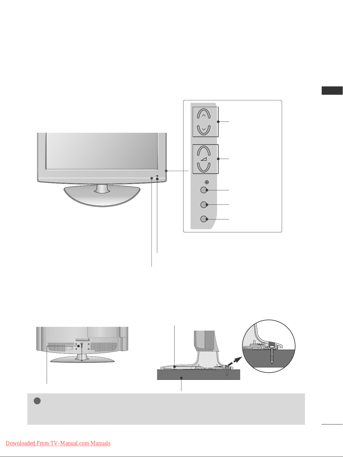
FRONT PANEL CONTROLS
■
Image shown may differ from your TV.
■
If your TV has a protection film attached, remove the film and then wipe the TV with a polishing cloth.
PLASMA TV Models : 42/50PG20**, 42/50/60PG30
**
PLASMA TV Models : 42/50PG10
**
PROGRAMMEVOLUMEMENU OKINPUT
Remote Control Sensor
POWER
Power/Standby Indicator
• illuminates red in standby mode.
• illuminates green when the TV is
switched on.
P
- +
OK
MENU
INPUT
MENU OK INPUT POWER
VOLUME PROGRAMME
Remote Control Sensor
Power/Standby Indicator
• illuminates red in standby mode.
• illuminates green when the TV is switched on.
P
- +
OK
MENU
INPUT
Downloaded From TV-Manual.com Manuals
5
PREPARATION
LCD TV Models :
26/32/37/42LG30**, 32/37/42/47/52LG50
**
Intelligent Sensor
Adjusts picture according to the surrounding
conditions. (32/37/42/47/52LG50**only)
POWER
Remote Control Sensor
Power/Standby Indicator
• illuminates red in standby mode.
• illuminates blue when the TV is switched on.
Note:
You can adjust
PPoowweerr IInnddiiccaattoorr
in
the
OPTION menu.
PROGRAMME
VOLUME
OK
MENU
INPUT
Attaching the TV to a desk (Only 26/32/42LG30
**
, 32/42LG50**)
WARNING
!
GG
To prevent TV from falling over, the TV should be securely attached to the floor/wall per installation
instructions. Tipping, shaking, or rocking the machine may cause injury.
The TV must be attached to desk so it cannot be pulled in a forward/backward direction, potentially causing
injury or damaging the product. Use only an attached screw.
1-Screw
(provided as parts of the product)
Desk
Stand
P
+
-
OK
MENU
INPUT
Downloaded From TV-Manual.com Manuals
PROGRAMMEVOLUME
MENU
OK
INPUT
PROGRAMMEVOLUME
MENU
OK
INPUT
POWER
6
PREPARATION
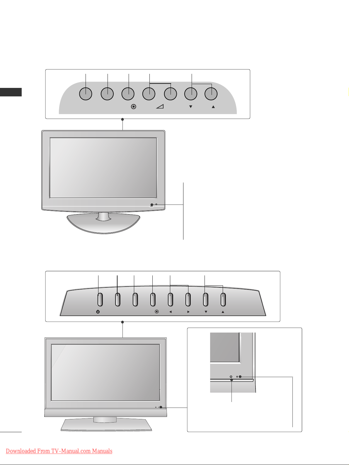
PREPARATION
Remote Control Sensor
Power/Standby Indicator
• illuminates red in standby mode.
• illuminates green when the TV is switched on.
LCD TV Models : 19/22LS4D
*
LCD TV Models : 19/22LG30
**
POWER
Remote Control Sensor
Power/Standby Indicator
• illuminates red in standby mode.
• illuminates blue when the TV is switched on.
Note:
You can adjust
PPoowweerr IInnddiiccaattoorr
in the OPTION
menu.
INPUT MENU P-+OK
/I
INPUT
MENU
PR
OK
VOL
Downloaded From TV-Manual.com Manuals
7
PREPARATION
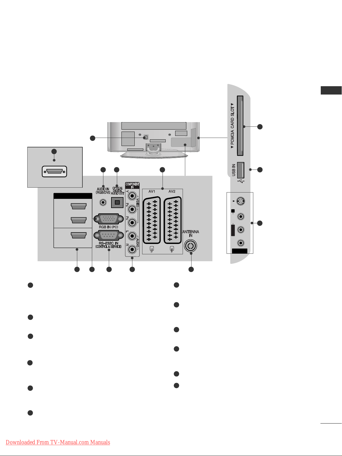
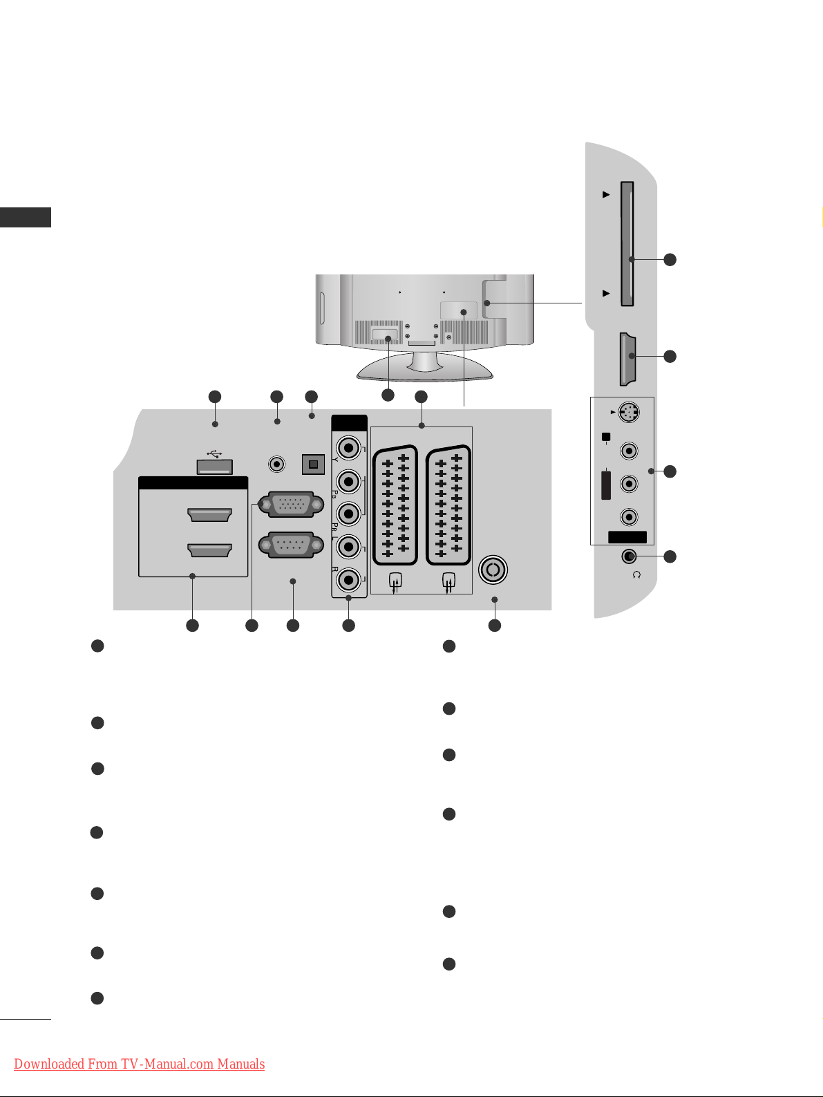
BACK PANEL INFORMATION
A
Image shown may differ from your TV.
PLASMA TV Models :
42/50PG10**, 42/50PG20**, 42/50/60PG30
**
Power Cord Socket
This TV operates on an AC power. The voltage is
indicated on the Specifications page. Never
attempt to operate the TV on DC power.
RGB/DVI Audio Input
Connect the audio from a PC or DTV.
OPTICAL DIGITAL AUDIO OUT
Connect digital audio from various types of equipment.
Note: In standby mode, these ports do not work.
Euro Scart Socket (AV1/AV2)
Connect scart socket input or output from an
external device to these jacks.
HDMI Input
Connect a HDMI signal to HDMI IN. Or DVI (VIDEO)
signal to HDMI/DVI port with DVI to HDMI cable.
RGB Input
Connect the output from a PC.
RS-232C IN (CONTROL & SERVICE) PORT
Connect to the RS-232C port on a PC.
Component Input
Connect a component video/audio device to
these jacks.
Antenna Input
Connect RF antenna to this jack.
PCMCIA (Personal Computer Memory Card
International Association) Card Slot
(This feature is not available in all countries.)
SERVICE ONLY PORT
Audio/Video Input (Except for 42/50PG10**)
Connect audio/video output from an external
device to these jacks.
S-Video Input (Except for 42/50PG10**)
Connect S-Video out from an S-VIDEO device.
1
2
3
4
5
6
7
8
9
10
11
12
1
AV IN 3
L/ MONO
R
AUDIO
VIDEO
S-VIDEO
AV IN 3
L/MONO
R
AUDIO
VIDEO
S-VIDEO
10
11
243
95 6 7 8
AV IN 3
L/ MONO
R
AUDIO
VIDEO
S-VIDEO
5
Only 42/50PG10
**
12
HDMI/DVI IN
3
HDMI IN
SERVICE ONLY
2
1
HDMI/DVI IN
Downloaded From TV-Manual.com Manuals
AUDIO
VIDEO
8
PREPARATION
PREPARATION
LCD TV Models:
19/22/26/32/37/42LG30
**
32/37/42/47/52LG50
**
Power Cord Socket
This TV operates on an AC power. The voltage is
indicated on the Specifications page. Never
attempt to operate the TV on DC power.
RGB/DVI Audio Input
Connect the audio from a PC or DTV.
DIGITAL AUDIO OUT OPTICAL
Connect digital audio from various types of equipment.
Note: In standby mode, these ports do not work.
Euro Scart Socket (AV1/AV2)
Connect scart socket input or output from an
external device to these jacks.
HDMI Input
Connect a HDMI signal to HDMI IN. Or DVI (VIDEO)
signal to HDMI/DVI port with DVI to HDMI cable.
RGB Input
Connect the output from a PC.
RS-232C IN (CONTROL & SERVICE) PORT
Connect to the RS-232C port on a PC.
Component Input
Connect a component video/audio device to
these jacks.
Antenna Input
Connect RF antenna to this jack.
PCMCIA (Personal Computer Memory Card
International Association) Card Slot
(This feature is not available in all countries.)
Audio/Video Input
Connect audio/video output from an external
device to these jacks.
S-Video Input
Connect S-Video out from an S-VIDEO device.
Headphone Socket
Connect the headphone plug to this socket.
SERVICE ONLY PORT
1
2
3
4
5
6
7
8
9
10
11
12
13
2
13
43
AV IN 3
H/P
L/MONO
R
AUDIO
HDMI IN 3
PCMCIA CARD SLOT
VIDEO
S-VIDEO
95 6 7 8
10
5
11
12
1
USB IN
SERVICE ONLY
HDMI/DVI IN
2
1(DVI)
OPTICAL
AUDIO IN
DIGITAL
(RGB/DVI)
AUDIO OUT
RGB IN
(PC)
RS-232C IN
(CONTROL & SERVICE)
COMPONENT
IN
VIDEO AUDIO
AV 1 AV 2
ANTENNA IN
PCMCIA CARD SLOT
HDMI IN 3
AUDIO
VIDEO
Downloaded From TV-Manual.com Manuals
9
PREPARATION
AUDIO IN
(RGB/DVI)
Y
PB
PR
LR
VIDEO
COMPONENT IN
AUDIO
EJECT PCMCIA
CARD SLOT
RS-232C IN
(CONTROL & SERVICE)
SERVICE
ONLY
RGB (PC) IN
HDMI/DVI IN
AV 1 AV 2
ANTENNA IN
5
32
4
7 8 10
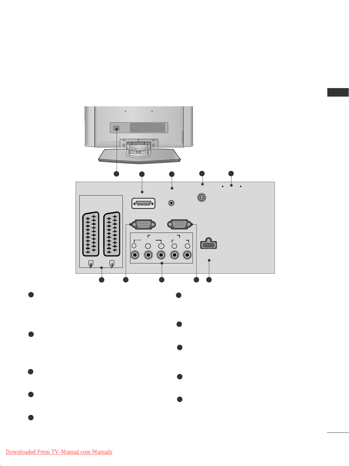
Power Cord Socket
This TV operates on an AC power. The voltage is
indicated on the Specifications page. Never
attempt to operate the TV on DC power.
HDMI Input
Connect a HDMI signal to HDMI IN.
Or DVI(VIDEO)signal to HDMI/DVI port with DVI
to HDMI cable.
RGB/DVI Audio Input
Connect the audio from a PC or DTV.
Antenna Input
Connect RF antenna to this jack.
PCMCIA (Personal Computer Memory Card
International Association) Card Slot
(This feature is not available in all countries.)
Euro Scart Socket (AV1/AV2)
Connect scart socket input or output from an
external device to these jacks.
RS-232C IN (CONTROL & SERVICE) PORT
Connect to the RS-232C port on a PC.
Component Input
Connect a component video/audio device to
these jacks.
RGB Input
Connect the output from a PC.
SERVICE ONLY PORT
1
2
3
4
5
6
7
8
9
10
6
1
9
LCD TV Models : 19/22LS4D
*
Downloaded From TV-Manual.com Manuals
10
PREPARATION
PREPARATION
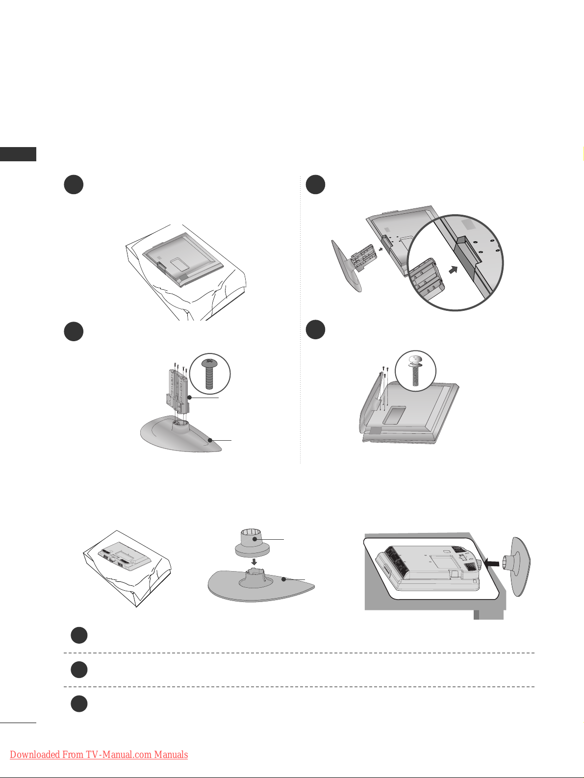
1 3
4
Carefully place the TV screen side down on a
cushioned surface to protect the screen from
damage.
2
Assemble the parts of the
SSttaanndd BB ooddyy
with
the
CC oo vvee rr BB aassee
of the TV.
Assemble the TV as shown.
Fix the 4 bolts securely using the holes in the
back of the TV.
Stand Body
Cover Base
STAND INSTALLATION
(LCD TV Models:
26/32/37/42LG30
**,
32/37/42LG50
**
)
A
When assembling the desk type stand, check whether the bolt is fully tightened. (If not tightened fully, the
product can tilt forward after the product installation.) If you tighten the bolt with excessive force, the bolt
can deviate from abrasion of the tightening part of the bolt.
(Only 19/22LG30**)
Carefully place the TV screen side down on a cushioned surface to protect the screen from damage.
Assemble the parts of the
SSTTAA NNDD BBOO DDYY
with
CC OOVVEE RR BB AASSEE
of the TV. Insert the
SSTTAA NNDD BBOO DDYY
into a
CC OOVVEE RR BBAASSEE
until clicking sound.
Assemble the TV as shown.
1
2
3
Stand Body
Cover Base
Downloaded From TV-Manual.com Manuals
11
PREPARATION
Carefully place the TV screen side down on a cushioned surface to protect the screen from damage.
Assemble the TV as shown.
Fix the 4 bolts securely using the holes in the back of the TV.
(Only
42PG10**, 42PG20**, 42PG30**)
1
2
3
Downloaded From TV-Manual.com Manuals
12
PREPARATION
PREPARATION
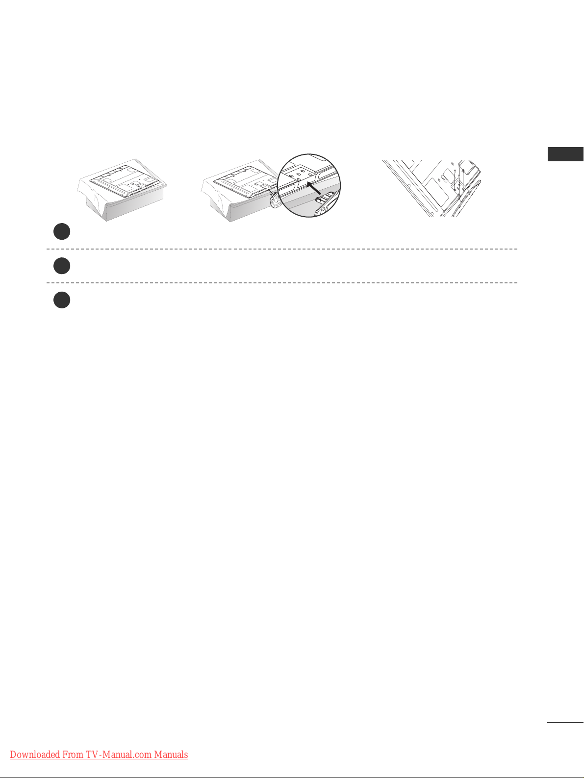
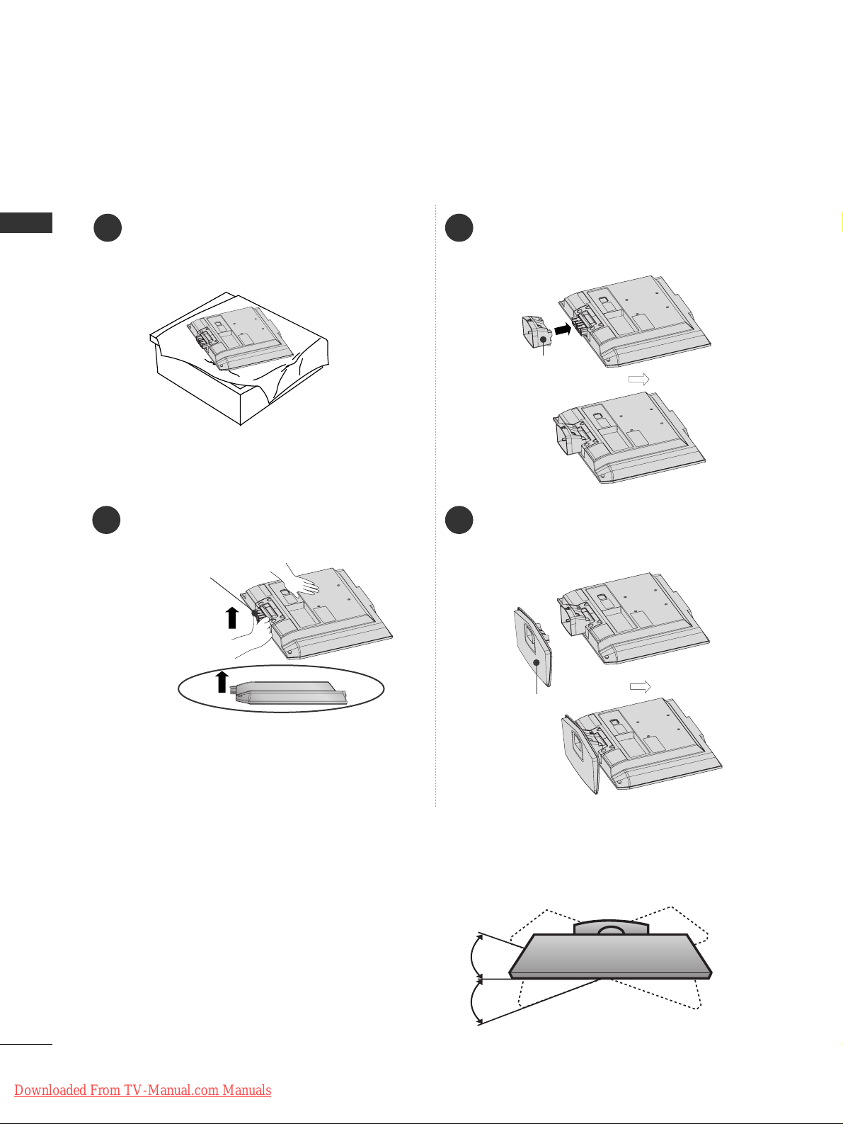
STAND INSTALLATION (Only 19/22LS4D
*
)
■
Image shown may differ from your TV.
1
2
3
4
Carefully place the TV screen side down on a
cushioned surface to protect the screen from
damage.
Hold the
HHii nnggee BB ooddyy
and bend it upward.
Hinge Body
Insert the
SSttaanndd BBooddyy
into the TV until clicking
sound.
Assemble the parts of the
SSttaanndd BB ooddyy
with
the
CC oo vvee rr BB aassee
of the TV.
Cover Base
Stand Body
Swivel Stand
(Except for 19/22LS4D*, 50PG10**)
After installing the TV, you can adjust the TV manually
to the left or right direction by 20 degrees to suit your
viewing position.
Downloaded From TV-Manual.com Manuals
13
PREPARATION
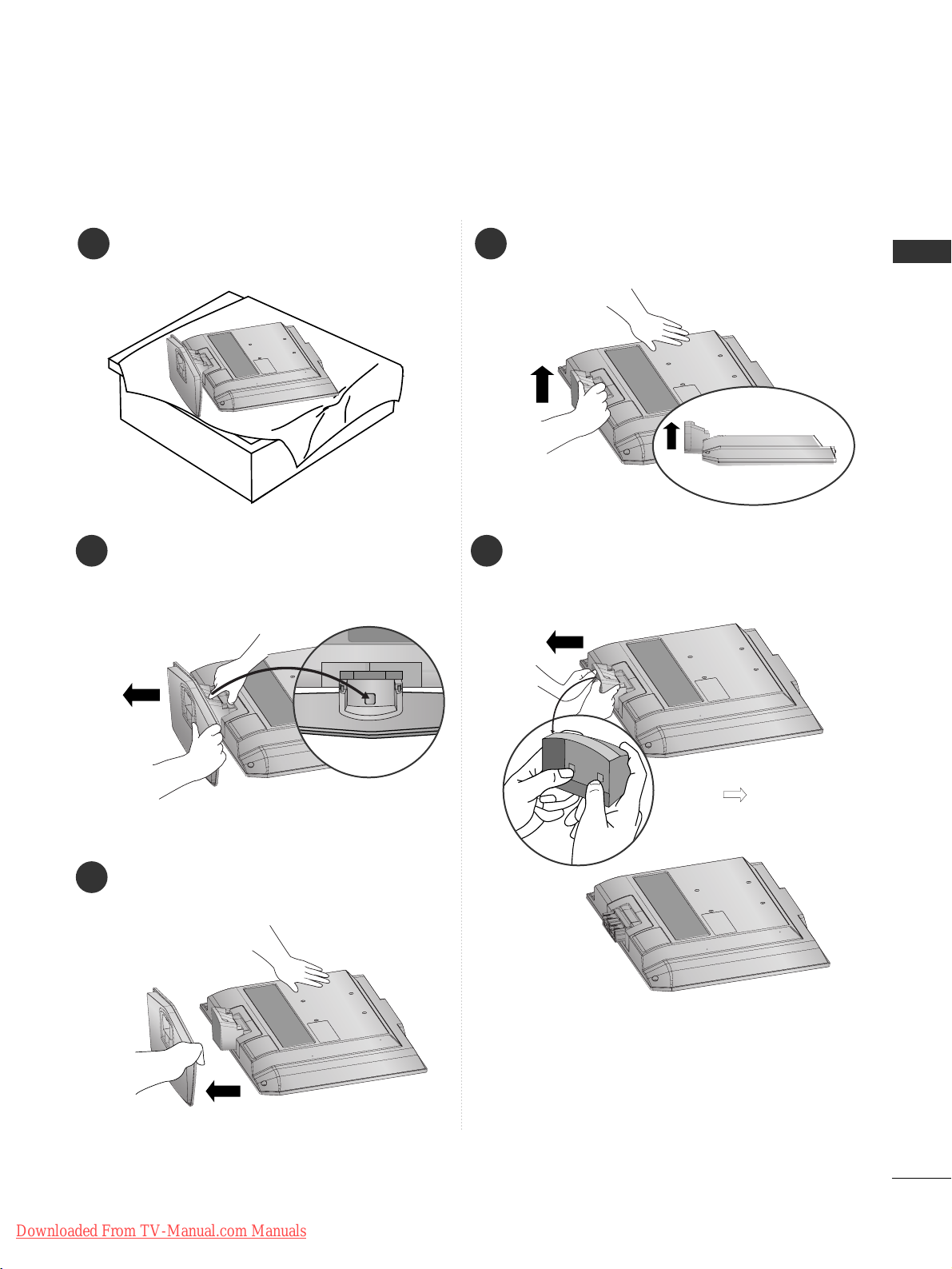
DETACHING STAND (Only 19/22LS4D
*
)
1
2
3
Place the tv with its front facing downward on a
cushion or soft cloth.
Pull
the
CC oo vvee rr BB aassee
backward during pressing
a button on the
SSttaanndd BB ooddyy
.
Hold
the
CC oo vvee rr BB aassee
and pull with shake it
backward to separate from the
SSttaanndd BB ooddyy
.
4
Hold the
SSttaanndd BB ooddyy
and bend it upward.
5
Pull stand body to separate from the TV during
pressing 2 latches.
■
Image shown may differ from your TV.
Downloaded From TV-Manual.com Manuals
14
PREPARATION
PREPARATION
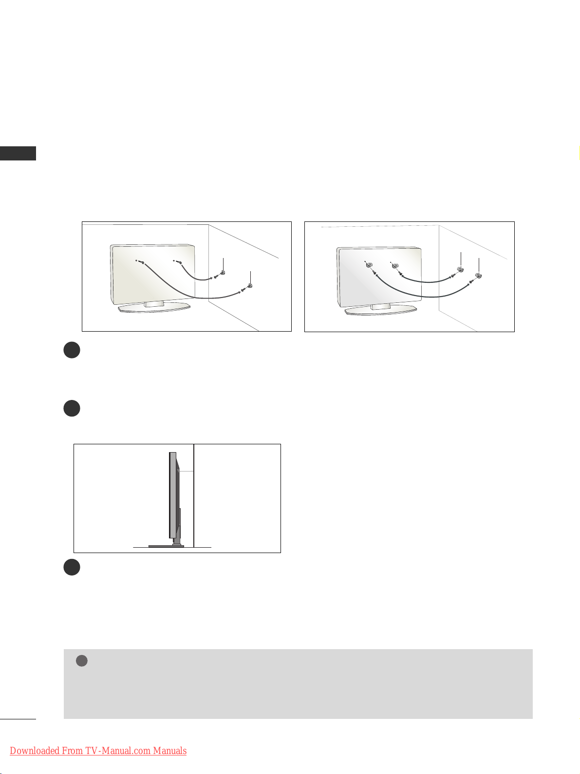
PLEASE SET IT UP CAREFULLY SO THE PRODUCT DOES NOT FALL OVER.
■
You should purchase necessary components to fix the TV to the wall on the market.
■
Position the TV close to the wall to avoid the possibility of it falling when pushed.
■
The instructions shown below are a safer way to set up the TV, which is to fix it to the wall, avoiding the
possibility of it falling forwards if pulled. This will prevent the TV from falling forward and causing injury. This
will also prevent the TV from damage. Ensure that children do not climb or hang from the TV.
NOTE
!
G
When moving the TV undo the cords first.
G
Use a platform or cabinet strong and large enough to support the size and weight of the TV.
G
To use the TV safely make sure that the height of the bracket on the wall and on the TV is the same.
3
1
2
Use the eye-bolts or TV brackets/bolts to fix the TV to the wall as shown in the picture.
(If your TV has bolts in the eyebolts, loosen these bolts.)
* Insert the eye-bolts or TV brackets/bolts and tighten them securely in the upper holes.
Secure the wall brackets with the bolts on the wall. Match the height of the bracket that is mounted on the
wall.
3
Use a sturdy rope to tie the TV. It is safer to tie the rope so it becomes horizontal between the wall and the
TV.
2
1
2
1
Downloaded From TV-Manual.com Manuals
15
PREPARATION
BACK COVER FOR WIRE ARRANGEMENT
PLASMA TV Models
Connect the cables as necessary.
To connect additional equipment, see the
EExxtteerrnnaall EEqquuiippmm eenntt SSee ttuupp
section.
1
Install the
CC AABB LLEE MMAA NNAAGGEE MMEE NNTT CCLLIIPP
as shown.
If your TV has the CABLE HOLDER, install it as shown and bundle the cables.
2
CABLE MANAGEMENT CLIP
Hold the
CC AABB LLEE MMAA NNAAGGEE MMEE NNTT CCLLIIPP
with both hands and pull it upward.
* For the 42PG10**model, press the center of the CABLE MANAGEMENT CLIP and then lift up it.
How to remove the cable management clip
(Only
42/50PG10**) (Only
42/50PG20**,
42/50/60PG30**)
(Only
42/50PG10**) (Only
42/50PG20**,
42/50/60PG30**)
CABLE MANAGEMENT CLIP
CABLE HOLDER
CABLE HOLDER
Downloaded From TV-Manual.com Manuals

16
PREPARATION
PREPARATION
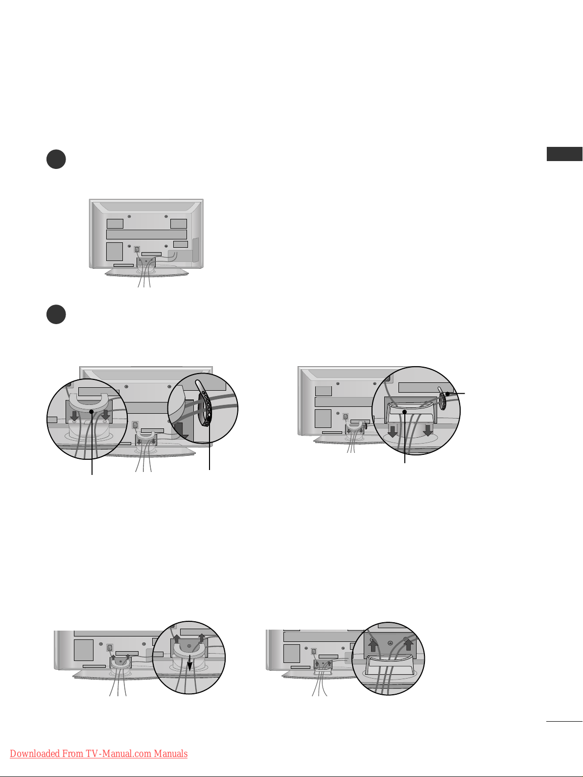
LCD TV Models:
26/32/37/42LG30
**
32/37/42/47/52LG50
**
Connect the cables as necessary.
To connect additional equipment, see the External
Equipment Setup section of
the manual.
1
Open the
CC AABB LL EE MMAANN AAGGEE MMEE NNTT CCLL II PP
as
shown and manage the cables.
2
CABLE MANAGEMENT CLIP
Fit the
CC AABB LL EE MMAANN AAGGEE MMEE NNTT CCLL II PP
as
shown.
3
Connect the cables as necessary.
To connect additional equipment, see the
External Equipment Setup section.
1
Install the CABLE MANAGEMENT CLIP as shown.
2
First, press the cable management. Hold the
CC AABB LL EE MMAANN AAGGEE MMEE NNTT CCLL II PP
with both hands and pull it upward.
NOTE
!
GG
Do not use the CABLE MANAGEMENT CLIP to lift the TV.
- If the TV is dropped, you may be injured or the TV may be damaged.
How to remove the cable management clip (LCD TV Models : 19/22LS4D
*
)
LCD TV Models : 19/22LS4D
*
Downloaded From TV-Manual.com Manuals
17
PREPARATION
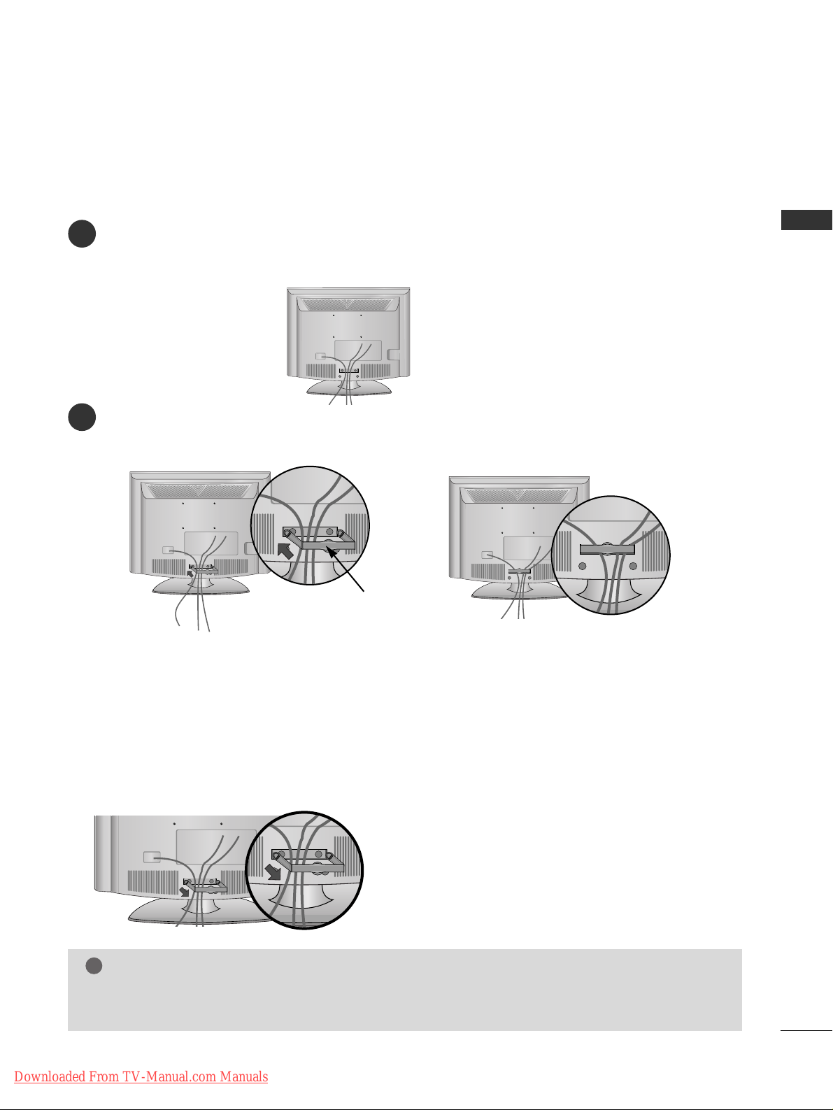
LCD TV Models : 19/22LG30
**
Connect the cables as necessary.
To connect additional equipment, see the External Equipment Setup section of the manual.
1
Install the CABLE MANAGEMENT CLIP as shown.
2
CABLE MANAGEMENT CLIP
NOTE
!
GG
Do not use the CABLE MANAGEMENT CLIP to lift the TV.
- If the TV is dropped, you may be injured or the TV may be damaged.
How to remove the cable management clip
GG
Hold the CABLE MANAGEMENT CLIP with both hands and pull it backward.
Downloaded From TV-Manual.com Manuals
18
PREPARATION
PREPARATION
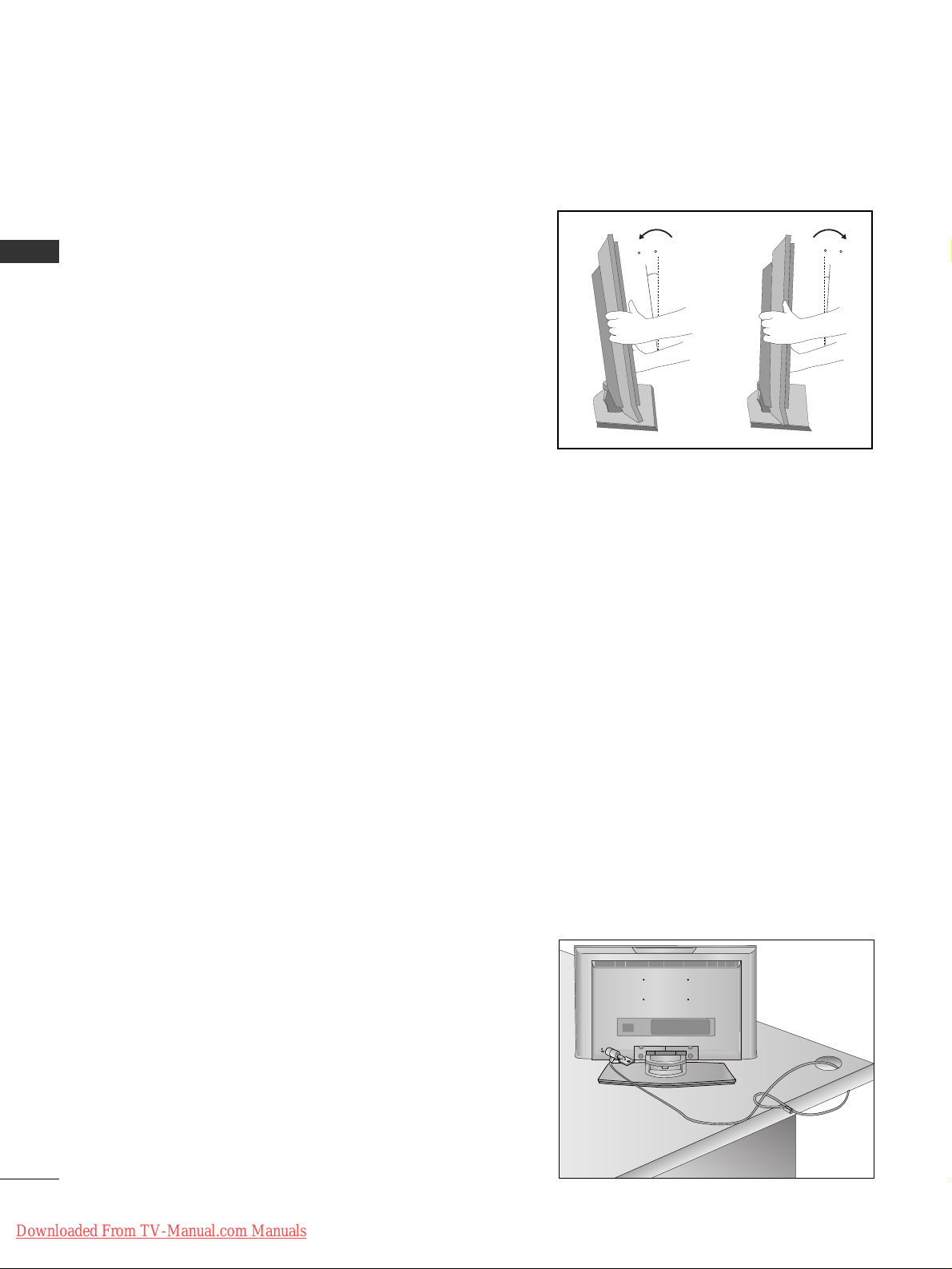
POSITIONING YOUR DISPLAY (Only 19/22LG30
**
, 19/22LS4D*)
■
Image shown may differ from your TV.
■
Adjust the position of the panel in various ways for
maximum comfort.
• Tilt range
10~12
3
0
LOCATION (Only 19/22LG30
**
, 19/22LS4D*)
Position your TV so that no bright light or sunlight falls directly onto the screen. Care should be taken not to
expose the tv to any unnecessary vibration, moisture, dust or heat. Also ensure that the TV is placed in a position
to allow a free flow of air. Do not cover the ventilation openings on the back cover.
If you intend to mount the TV to a wall, attach VESA standard mounting interface (optional parts) to the back of
the TV.
When you install the TV to use the wall mounting bracket (optional parts), fix it carefully so as not to drop.
KENSINGTON SECURITY SYSTEM
(Only 19/22LG30**, 19/22LS4D*)
The TV is equipped with a Kensington Security System connector on the back panel. Connect the Kensington
Security System cable as shown below.
For the detailed installation and use of the Kensington Security System, refer to the user’s guide provided with
the Kensington Security System.
For further information, contact http://www.kensington.com, the internet homepage of the Kensington
company. Kensington sells security systems for expensive electronic equipment such as notebook PCs and LCD
projectors.
NOTE
- The Kensington Security System is an optional accessory.
NOTES
a. If the TV feels cold to the touch, there may be a small “flicker”
when when it is turned on.
This is normal, there is nothing wrong with TV.
b. Some minute dot defects may be visible on the screen, appear-
ing as tiny red, green, or blue spots. However, they have no
adverse effect on the monitor's performance.
c. Avoid touching the LCD screen or holding your finger(s)
against it for long periods of time.
Doing so may produce some temporary distortion effects on
the screen.
Downloaded From TV-Manual.com Manuals
19
PREPARATION
DESKTOP PEDESTAL INSTALLATION
For adequate ventilation allow a clearance of 4” (10cm) all around the TV.
EARTHING
Ensure that you connect the earth wire to prevent possible
electric shock. If grounding methods are not possible, have a
qualified electrician install a separate circuit breaker.
Do not try to earth the TV by connecting it to telephone
wires, lightening rods or gas pipes.
Power Supply
Circuit
breaker
■
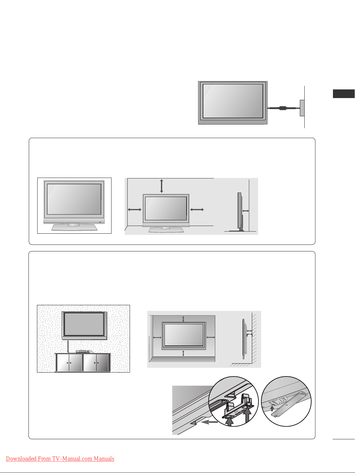
The TV can be installed in various ways such as on a wall, or on a desktop etc.
■
The TV is designed to be mounted horizontally.
4 inches
4 inches 4 inches 4 inches
WALL MOUNT: HORIZONTAL INSTALLATION
For adequate ventilation allow a clearance of 4” (10cm) all around the TV. We recommend that you
use a wall mounting bracket of LG brand when mounting the TV to a wall.
4 inches
4 inches
4 inches 4 inches
4 inches
When installing the wall-mounted unit, use the
protection cover for desk-type stand installation.
Insert the
PPRROOTTEECCTTIIOONN CCOOVV EE RR
into the TV
until clicking sound.
Not using the desk-type stand
(Except for 19/22LS4D*)
■
Image shown may differ from your TV.
< PLASMA TV > < LCD TV >
R
Downloaded From TV-Manual.com Manuals
20
PREPARATION
PREPARATION
ANTENNA IN
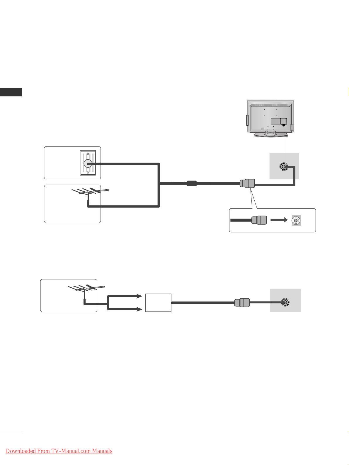
■
For optimum picture quality, adjust antenna direction.
■
An antenna cable and converter are not supplied.
■
To prevent damage do not connect to the mains outlet until all connections are made between the devices.
Multi-family Dwellings/Apartments
(Connect to wall antenna socket)
Single-family Dwellings /Houses
(Connect to wall jack for outdoor antenna)
Outdoor
Antenna
(VHF, UHF)
Wall
Antenna
Socket
RF Coaxial Wire (75 ohm)
ANTENNA CONNECTION
Antenna
UHF
Signal
Amplifier
VHF
■
In poor signal areas, to achieve better picture quality it may be necessary to install a signal amplifier to the
antenna as shown above.
■
If signal needs to be split for two TVs, use an antenna signal splitter for connection.
AV IN 3
L/MONO
R
AUDIO
VIDEO
S-VIDEO
ANTENNA IN
Downloaded From TV-Manual.com Manuals
21
EXTERNAL EQIPMENT SETUP
EXTERNAL EQUIPMENT SETUP
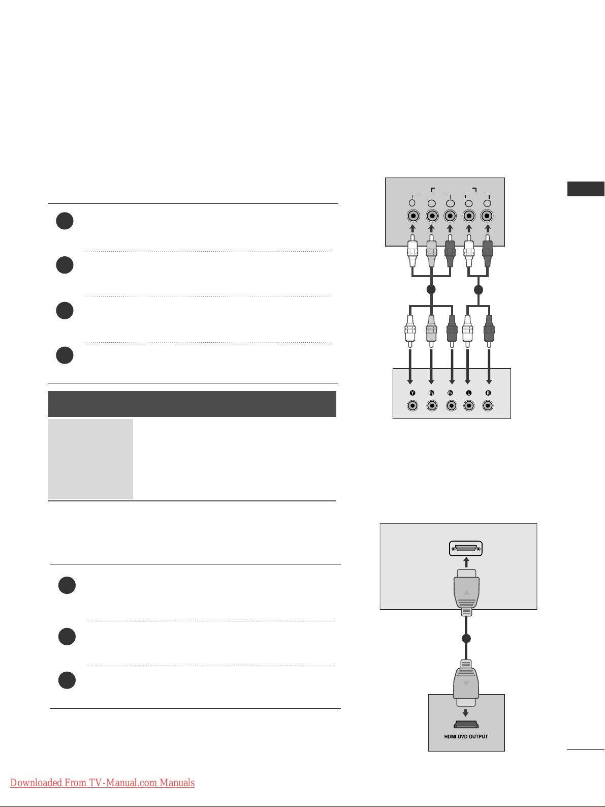
Connect the video outputs (Y, P
B, PR
)
of the digital set
top box to the
CC OOMMPPOONN EENNTT IINN VVII DDEEOO
jacks on the TV.
Connect the audio output of the digital set-top box to
the
CC OOMMPPOONN EENNTT IINN AA UUDDIIOO
jacks on the TV.
Turn on the digital set-top box.
(
Refer to the owner’s manual for the digital set-top box.
)
Select
CCoo mmppoonn ee nntt
input source using the
II NNPPUUTT
button
on the remote control.
2
3
4
1
HD RECEIVER SETUP
■
To avoid damaging any equipment, never plug in any power cords until you have finished connecting all equipment.
■
This section on EXTERNAL EQUIPMENT SETUP mainly uses diagrams for the 22LS4D*models.
Connecting with a component cable
Y
PBPR
LR
VIDEO
COMPONENT IN
AUDIO
1
2
Signal
480i/576i
480p/576p
720p/1080i
10 8 0 p
Component
Yes
Yes
Yes
Yes
(50/60Hz)
HDMI
No
Yes
Yes
Yes
Connecting a set-top box with an HDMI cable
Connect the HDMI output of the digital set-top box to the
HHDDMMII//DD VVII IINN,HHDDMMII//DD VVII IINN 11,HHDDMMII IINN 22
or
HHDDMMII IINN 33
jack on the TV.
Turn on the digital set-top box.
(
Refer to the owner’s manual for the digital set-top box.
)
Select HDMI/DVI, HDMI1, HDMI2 or HDMI3 input source
using the
II NNPPUU TT
button on the remote control.
2
3
1
HDMI/DVI IN
1
■
This TV can receive Digital RF/Cable signals without an external digital set-top box. However, if you do receive
Digital signals from a digital set-top box or other digital external device, refer to the diagram as shown below.
Downloaded From TV-Manual.com Manuals
22
EXTERNAL EQIPMENT SETUP
EXTERNAL EQUIPMENT SETUP
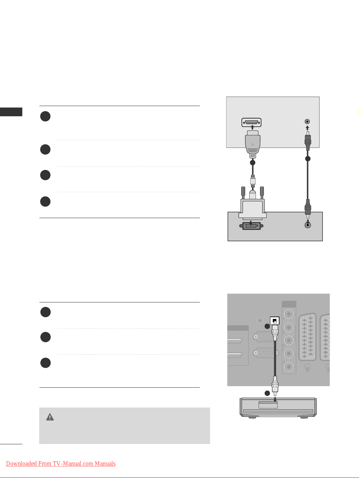
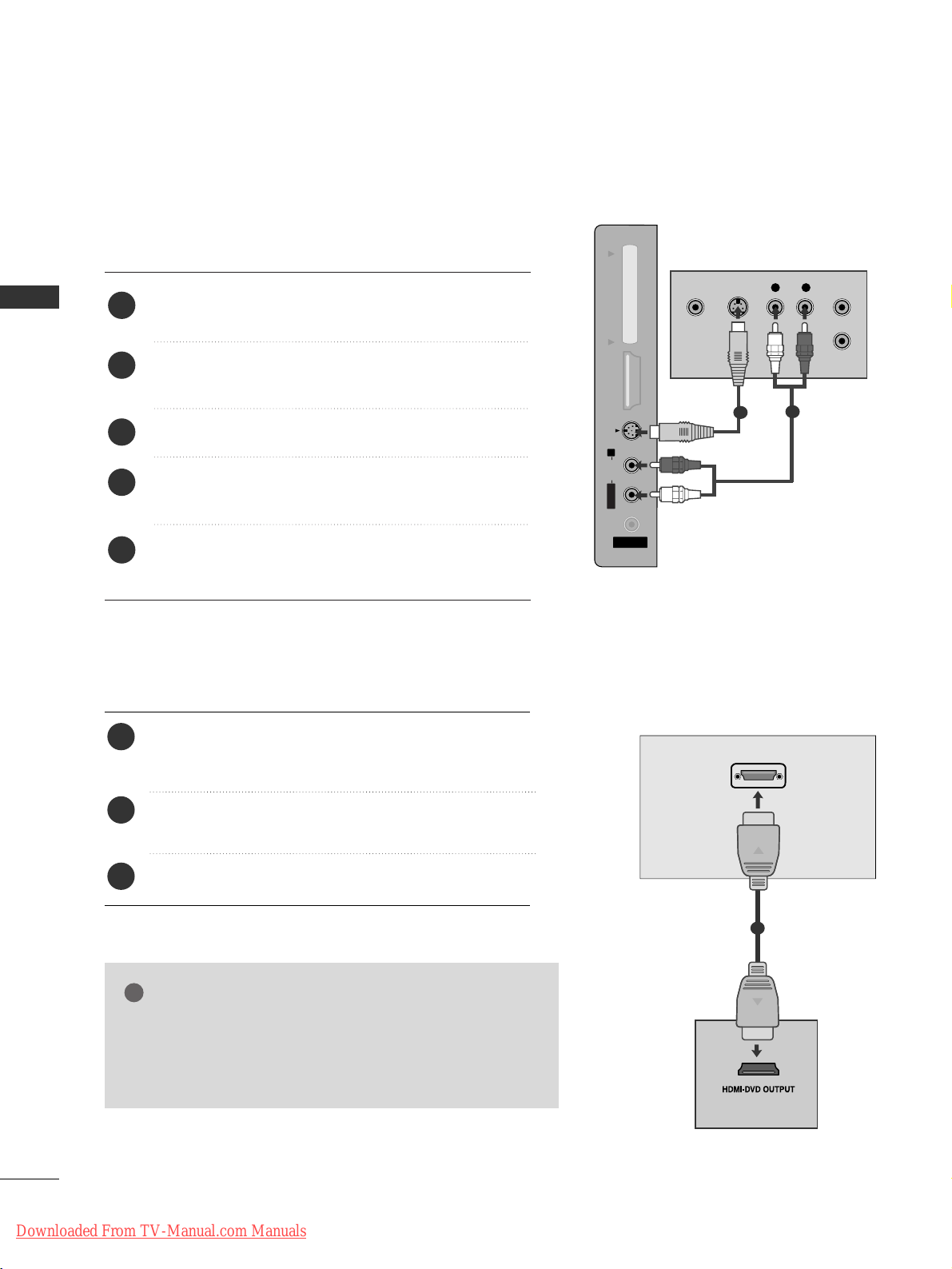
Connect the digital set-top box to
HHDD MMII // DDVV II II NN
,
HHDD MMII//DD VVII IINN 11((DDVV II ))
or
HHDD MMII // DDVVII IINN 11
jack on
the TV.
Connect the audio output of the digital set-top box to
the
AAUU DDIIOO II NN ((RRGGBB//DDVVII))
jack on the TV.
Turn on the digital set-top box. (Refer to the owner’s
manual for the digital set-top box.
)
Select HDMI/DVI or HDMI 1 input source using the
II NNPPUUTT
button on the remote control.
2
3
4
1
Connecting with a HDMI to DVI cable
DVI-PC OUTPUT
AUDIO
HDMI/DVI IN
AUDIO IN
(RGB/DVI)
1
2
DIGITAL AUDIO OUT SETUP
(Except for 19/22LS4D*)
- Sending the TV’s audio signal to external audio equipment via
the Digital Audio Output (Optical) port.
G
Do not look into the optical output port. Looking at the
laser beam may damage your vision.
CAUTION
RGB IN
(PC)
OPTICAL
DIGITAL
AUDIO OUT
AV 1 AV
RS-232C IN
(CONTROL & SERVICE)
AUDIO IN
(RGB/DVI)
COMPONENT
IN
VIDEO AUDIO
Connect one end of an optical cable to the TV Digital
Audio (Optical)Output port.
Connect the other end of the optical cable to the
digital audio (optical)input on the audio equipment.
Set the “ TV Speaker option - Off ” in the AUDIO
menu. (
G
pp..8800
) Refer to the external audio equipment
instruction manual for operation.
2
3
1
1
2
Downloaded From TV-Manual.com Manuals
23
EXTERNAL EQIPMENT SETUP
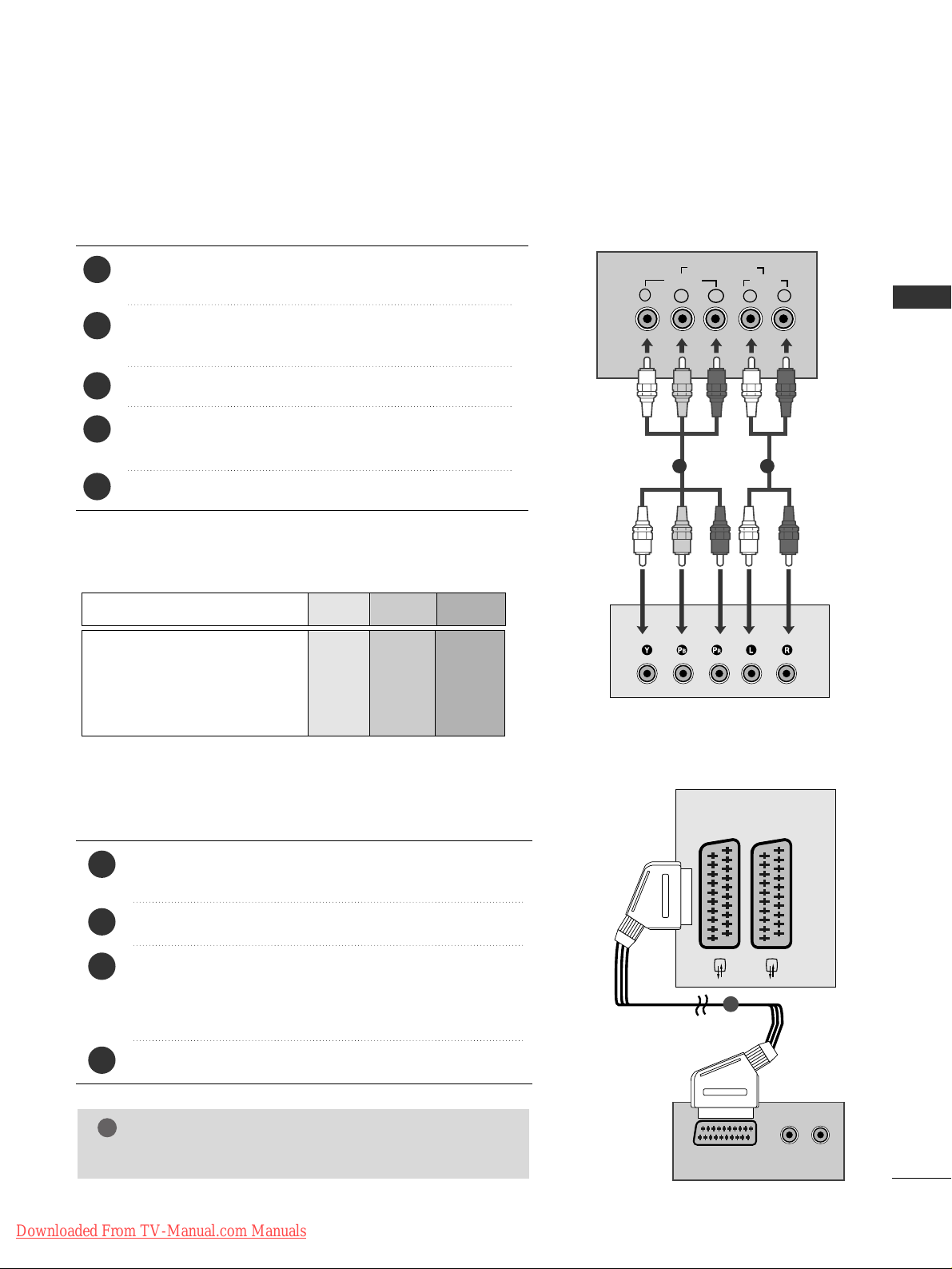
DVD SETUP
When connecting with a component cable
AV 1 AV 2
Y
PBPRLR
VIDEO
COMPONENT IN
AUDIO
Component Input ports
To achieve better picture quality, connect a DVD player to
the component input ports as shown below.
Component ports on the TV
YPBP
R
Video output ports
on DVD player
Y
Y
Y
Y
PB
B-Y
Cb
Pb
P
R
R-Y
Cr
Pr
Connect the video outputs (Y, P
B, PR
)
of the DVD to the
CC OOMMPPOONN EENNTT II NN VV IIDDEE OO
jacks on the TV.
Connect the audio outputs of the DVD to the
CC OOMMPPOONN EENNTT IINN AA UUDDIIOO
jacks on the TV.
Turn on the DVD player, insert a DVD.
Select
CCoo mmppoonn ee nntt
input source using the
II NNPPUUTT
button
on the remote control.
Refer to the DVD player's manual for operating instructions.
2
3
4
5
1
1 2
(R) AUDIO (L)
AUDIO/
VIDEO
AV 1 AV 2
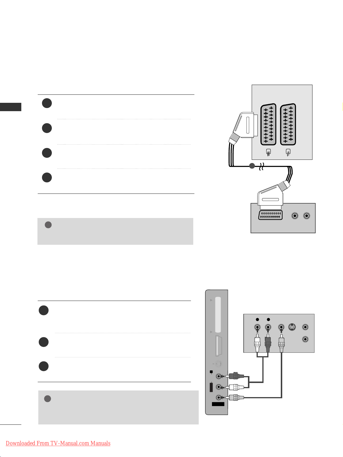
Connecting with a Euro Scart cable
Connect the Euro scart socket of the DVD to the
AAVV11
Euro scart socket on the TV.
Turn on the DVD player, insert a DVD.
Select
AA VV 11
input source using the
II NNPPUUTT
button on the
remote control.
If connected to
AA VV 22
Euro scart socket, select
AA VV 22
input
source.
Refer to the DVD player's manual for operating instructions.
2
3
4
1
1
NOTE
!
GG
Any Euro scart cable used must be signal shielded.
Downloaded From TV-Manual.com Manuals
24
EXTERNAL EQIPMENT SETUP
EXTERNAL EQUIPMENT SETUP
HDMI/DVI IN
AV 1 AV 2
Connecting the HDMI cable
Connect the HDMI output of the DVD to the
HHDDMMII//DD VVII IINN,HHDDMMII//DD VVII IINN 11,HHDDMMII IINN 22
or
HHDDMMII IINN 33
jack on the TV.
Select HDMI/DVI,
HHDDMM II 11, HHDDMM II 22
or
HHDDMM II 33
input
source using the
II NNPPUUTT
button on the remote control.
Refer to the DVD player's manual for operating instructions.
2
3
1
1
GG
The TV can receive video and audio signals simultaneously
when using a HDMI cable.
GG
If the DVD does not support Auto HDMI, you must set the
output resolution appropriately.
NOTE
!
Connecting with a S-Video cable
(Except for 19/22LS4D*, 42/50PG10**)
AV IN 3
L/MONO
R
AUDIOAUDIO
HDMI IN 3HDMI IN 3 PCMCIA CARD SLOT PCMCIA CARD SLOT
VIDEOVIDEO
S-VIDEO
L R
S-VIDEOVIDEO
OUTPUT
SWITCH
ANT IN
ANT OUT
Connect the S-VIDEO output of the DVD to the
SS--VV IIDDEE OO
input on the TV.
Connect the audio outputs of the DVD to the
AAUU DD II OO
input jacks on the TV.
Turn on the DVD player, insert a DVD.
Select
AV 3 input source using the INPUT button on
the remote control.
Refer to the DVD player's manual for operating
instructions.
2
3
4
5
1
1
2
Downloaded From TV-Manual.com Manuals
25
EXTERNAL EQIPMENT SETUP
VCR SETUP
■
To avoid picture noise (interference), allow adequate distance between the VCR and TV.
■
If 4:3 picture format is used for an extended period the fixed images on the sides of the screen may remain
visible.
OUTPUT
SWITCH
ANT IN
R
S-VIDEO VIDEO
ANT OUT
L
ANTENNA IN
Wall Jack
Antenna
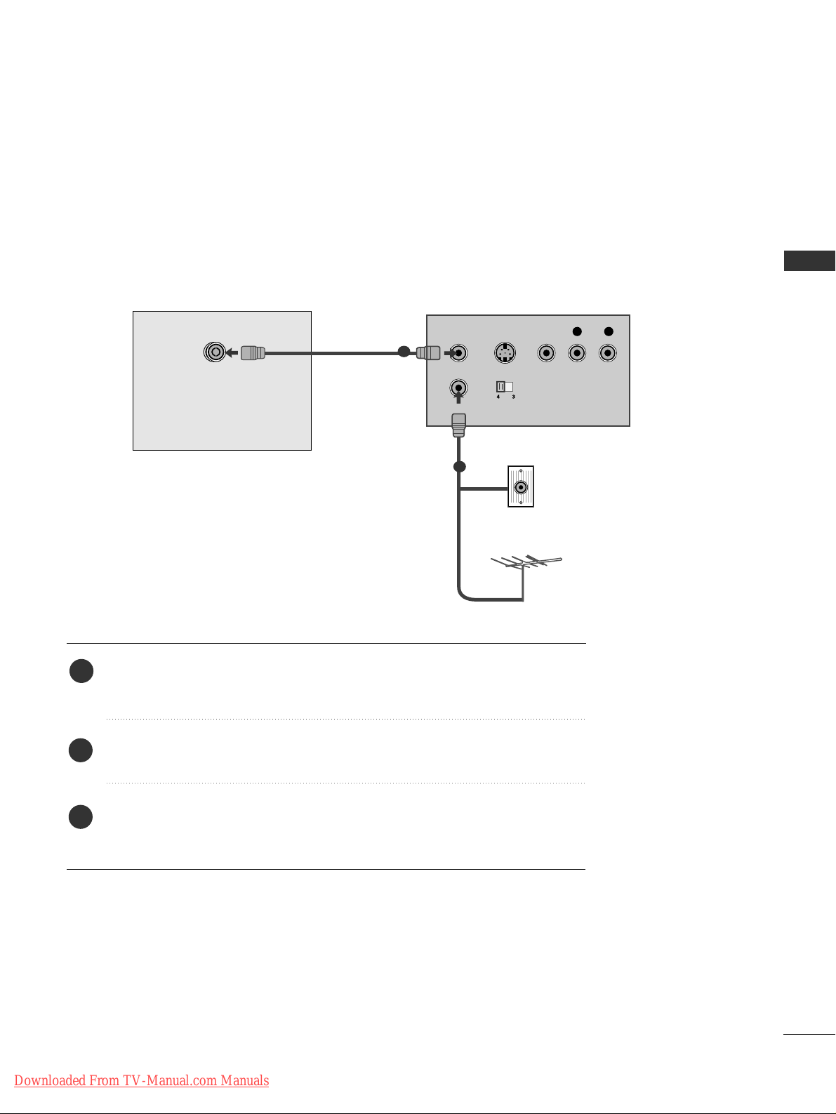
1
2
When connecting with a RF Cable
Connect the
AANN TT OOUU TT
socket of the VCR to the
AANNTTEE NNNN AA IINN
socket on the
TV.
Connect the antenna cable to the
AANN TT IINN
socket of the VCR.
Press the PLAY button on the VCR and match the appropriate channel between
the TV and VCR for viewing.
1
2
3
Downloaded From TV-Manual.com Manuals
26
EXTERNAL EQIPMENT SETUP
EXTERNAL EQUIPMENT SETUP
(R) AUDIO (L)
AUDIO/
VIDEO
AV 1 AV 2
Connecting with a Euro Scart cable
Connect the Euro scart socket of the VCR to the
AAVV11
Euro scart socket on the TV.
Insert a video tape into the VCR and press PLAY on
the VCR. (Refer to the VCR owner’s manual.)
Select
AA VV 11
input source using the
II NNPPUUTT
button on
the remote control.
If connected to
AAVV 22
Euro scart socket, select
AA VV 22
input source.
2
3
4
1
1
NOTE
!
GG
Any Euro scart cable used must be signal shielded.
Connecting with a RCA cable
(Except for 19/22LS4D*, 42/50PG10**)
AV IN 3
L/MONO
R
AUDIOAUDIO
HDMI IN 3HDMI IN 3 PCMCIA CARD SLOT PCMCIA CARD SLOT
VIDEOVIDEO
S-VIDEO
L
R
S-VIDEO
VIDEO
OUTPUT
SWITCH
ANT IN
ANT OUT
Connect the
AAUUDDII OO/VVIIDDEE OO
jacks between TV and
VCR. Match the jack colours (Video = yellow, Audio Left
= white, and Audio Right = red)
Insert a video tape into the VCR and press PLAY on
the VCR. (Refer to the VCR owner’s manual.
)
Select
AV 3 input source using the
II NNPPUUTT
button on
the remote control.
1
2
3
GG
If you have a mono VCR, connect the audio cable from the
VCR to the
AAUU DDIIOO LL // MMOONNOO
jack of the TV.
NOTE
!
Downloaded From TV-Manual.com Manuals
27
EXTERNAL EQIPMENT SETUP
GG
If both S-VIDEO and VIDEO sockets have been connected
to the S-VHS VCR simultaneously, only the S-VIDEO can
be received.
NOTE
!
AV IN 3
L/MONO
R
AUDIOAUDIO
HDMI IN 3HDMI IN 3 PCMCIA CARD SLOT PCMCIA CARD SLOT
VIDEOVIDEO
S-VIDEO
AV IN 3
L/ MONO
R
AUDIO
HDMI IN 3 PCMCIA CARD SLOT
VIDEO
S-VIDEO
L
R
S-VIDEO
VIDEO
OUTPUT
SWITCH
ANT IN
ANT OUT
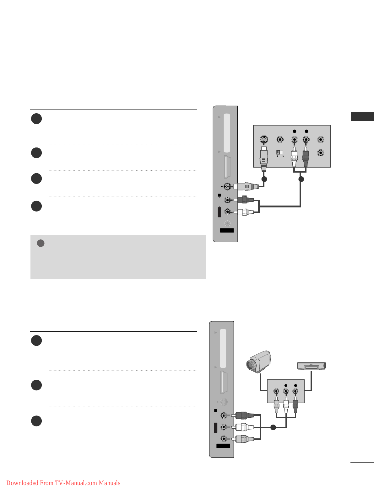
Connect the S-VIDEO output of the VCR to the S VIDEO input on the TV. The picture quality is improved;
compared to normal composite (RCA cable) input.
Connect the audio outputs of the VCR to the AUDIO
input jacks on the TV.
Insert a video tape into the VCR and press PLAY on the
VCR. (Refer to the VCR owner’s manual.)
Select
AV 3 input source using the
IINNPPUUTT
button on the
remote control.
2
3
4
1
1 2
AV IN 3
L/MONO
R
AUDIOAUDIO
HDMI IN 3HDMI IN 3 PCMCIA CARD SLOT PCMCIA CARD SLOT
VIDEOVIDEO
S-VIDEO
L R
VIDEO
Connect the
AAUU DD II OO/VVIIDD EEOO
jacks between TV and
external equipment. Match the jack colours
. (Video =
yellow, Audio Left = white, and Audio Right = red
)
Select AV 3 input source using the
II NNPPUUTT
button on
the remote control.
Operate the corresponding external equipment.
Refer to external equipment operating guide.
2
3
1
1
Camcorder
Video Game Set
Connecting with a S-Video cable
(Except for 19/22LS4D*, 42/50PG10**)
OTHER A/V SOURCE SETUP
(Except for 19/22LS4D*, 42/50PG10**)
Downloaded From TV-Manual.com Manuals

28
EXTERNAL EQIPMENT SETUP
EXTERNAL EQUIPMENT SETUP
PC SETUP
This TV provides Plug and Play capability, meaning that the PC adjusts automatically to the TV's settings.
Connecting with a D-sub 15 pin cable
RGB OUTPUT
AUDIO
AUDIO IN
(RGB/DVI)
RGB (PC) IN
1
2
4
Connect the RGB output of the PC to the
RRGGBB IINN
(( PPCC))
jack on the TV.
Connect the PC audio output to the
AAUU DD IIOO IINN
(( RRGGBB// DDVVII))
jack on the TV.
Turn on the PC and the TV
Select
RR GG BB
input source using the INPUT button on
the remote control.
2
3
1
Insert the CI Module to
PPCC MMCCIIAA
(Personal Computer
Memory Card International Association)
CC AARRDD SSLLOOTT
of TV as shown.
For further information, see p.54.
1
INSERTION OF CI MODULE
PCMCIA
CARD SLOT
TVTV
-- TT oo vv iieeww tthhee eenn cc rryy pp ttee dd ((ppaayy)) sseerrvviicceess iinn ddiiggii ttaall TT VV
mm oodd ee ..
-- TT hhiiss ffeeaattuu rree iiss nn oott aavvaa iillaabbllee iinn aallll ccoouunnttrrii eess ..
1
Downloaded From TV-Manual.com Manuals
Loading...