


 Loading...
Installation and
Operating Guide
20LH1DC1
Please read this manual carefully before operating your set.
Retain it for future reference.
Record model number and serial number of the set. See the label attached on the back cover and quote
this information to your dealer when you require service.
www.lgcommercial.com
WARNING / CAUTION
CAUTION:
TO REDUCE THE RISK OF ELECTRIC SHOCK DO NOT REMOVE COVER (OR BACK). NO USER SERVICEABLE PARTS INSIDE. REFER TO QUALIFIED SERVICE PERSONNEL.
The lightning flash with arrowhead
symbol, within an equilateral triangle, is intended to alert the user to the
presence of uninsulated “dangerous voltage” within the product’s enclosure that may be of sufficient magnitude to constitute a risk of electric shock to persons.
The exclamation point within an
equilateral triangle is intended to alert the user to the presence of important
operating and maintenance (servicing) instructions in the literature accompanying the appliance.
WARNING
TO PREVENT FIRE OR SHOCK HAZARDS, DO NOT EXPOSE THIS PRODUCT TO RAIN OR MOISTURE. THIS PRODUCT MUST BE USED WITH UL LISTED MOUNTING BRACKET.
IT IS FORBIDDEN TO CONNECT THIS TV TO ANY TELECOMMUNICATION NETWORK / TELEPHONE.
NOTE TO CABLE TV INSTALLER
This reminder is provided to call the CATV system installer’s attention to Article 820-40 of the National Electric Code (U.S.A.). The code provides guidelines for proper grounding and, in particular, specifies that the cable ground shall be connected to the grounding system of the building, as close to the point of the cable entry as practical.
REGULATORY INFORMATION
This equipment has been tested and found to comply with the limits for a Class B digital device, pursuant to Part 15 of the FCC Rules.
These limits are designed to provide reasonable protection against harmful interference when the equipment is operated in a residential installation. This equipment generates, uses and can radiate radio frequency energy and, if not installed and used in accordance with the instruction manual, may cause harmful interference to radio communications. However, there is no guarantee that interference will not occur in a particular installation.
If this equipment does cause harmful interference to radio or television reception, which can be determined by turning the equipment off and on, the user is encouraged to try to correct the
interference by one or more of the following measures:
•Reorient or relocate the receiving antenna.
•Increase the separation between the equipment and receiver.
•Connect the equipment into an outlet on a circuit different from that to which the receiver is connected.
•Consult the dealer or an experienced radio/TV technician for help.
WARNING
Changes or modifications not expressly approved by the party responsible for compliance could void the user’s authority to operate the equipment.
2

CAUTION
Do not attempt to modify this product in any way without written authorization from LG Electronics Corporation.
Unauthorized modification could void the user’s authority to operate this product.
CAUTION
THESE SERVICING INSTRUCTIONS ARE FOR USE BY QUALIFIED SERVICE PERSONNEL ONLY. TO REDUCE THE RISK OF ELECTRIC SHOCK, DO NOT PERFORM ANY SERVICING OTHER THAN THAT CONTAINED IN THE OPERATING INSTRUCTIONS UNLESS YOU ARE QUALIFIED TO DO SO.
CAUTION
1.Do not put this product next to the patient’s bed where it can be reached by the patient.
2.Install product in such a way that patients will not be able to touch this product.
3.This product should only be mounted on a wall.
WARNING
Apparatus shall not be exposed to dripping or splashing and no objects filled with liquids, such as vases, shall not be placed on the apparatus.
CAUTION
When used outside of the U.S., it may be used HAR cord with fitting of an approved agency is employed. (When used outside of U.S., other power supply cords may be used if the cord is approved by the local regulating agency.)
CLEANING AND DISINFECTION
Clean the exterior of this television by removing dust with a lint-free cloth.
CAUTION: To avoid damage to the surface of the television, do not use abrasive or chemical cleaning agents.
DISCONNECTING DEVICE FROM MAINS
Main plug is the disconnecting device. The plug must remain readily operable.
IMPORTANT SAFEGUARDS FOR YOU AND YOUR NEW PRODUCT
YOUR PRODUCT HAS BEEN MANUFACTURED AND TESTED WITH YOUR SAFETY IN MIND. HOWEVER, IMPROPER USE CAN RESULT IN POTENTIAL ELECTRICAL SHOCK OR FIRE HAZARDS. TO AVOID DEFEATING THE SAFEGUARDS THAT HAVE BEEN BUILT INTO YOUR NEW PRODUCT, PLEASE READ AND OBSERVE THE FOLLOWING SAFETY POINTS WHEN INSTALLING AND USING YOUR NEW PRODUCT, AND SAVE THEM FOR FUTURE REFERENCE. OBSERVING THE SIMPLE PRECAUTIONS DISCUSSED IN THIS MANUAL CAN HELP YOU GET MANY YEARS OF ENJOYMENT AND SAFE OPERATION THAT ARE BUILT INTO YOUR NEW PRODUCT.
 NOTE
NOTE
G If the TV feels cold to the touch, there may be a small “flicker” when it is turned on. This is normal, there is nothing wrong with the TV.
G Some minute dot defects may be visible on the screen, appearing as tiny red, green, or blue spots. However, they have no adverse effect on the TVs performance.
G Avoid touching the LCD screen or holding your finger(s) against it for long periods of time. Doing so may produce some temporary distortion effects on the screen.
3

SAFETY INSTRUCTIONS
IMPORTANT SAFETY INSTRUCTIONS
1.Read these instructions.
2.Keep these instructions.
3.Heed all warnings.
4.Follow all instructions.
5.Do not use this apparatus near water.
6.Clean only with dry cloth.
7.Do not block any ventilation openings. Install in accordance with the manufacturer’s instructions.
8.Do not install near any heat sources such as radiators, heat registers, stoves, or other apparatus (including amplifiers) that produce heat.
9.Do not defeat the safety purpose of the polarized or grounding-type plug. A polarized plug has two blades with one wider than the other. A grounding type plug has two blades and a third grounding prong. The wide blade or the third prong is provided for your safety. If the provided plug does not fit into your outlet, consult an electrician for replacement of the obsolete outlet.
10.Protect the power cord from being walked on or pinched particularly at plugs, convenience receptacles, and the point where they exit from the apparatus.
11.Only use attachments/accessories specified by the manufacturer.
12.Use only with the cart, stand, tripod, bracket, or table specified by the manufacturer, or sold with the apparatus. When a cart is used, use caution when moving the cart/apparatus combination to avoid injury from tip-over.
13.Unplug this apparatus during lightning storms or when unused for long periods of time.
14.Refer all servicing to qualified service personnel. Servicing is required when the apparatus has been damaged in any way, such as power-supply cord or plug is damaged, liquid has been spilled or object have fallen into the apparatus, the apparatus has been exposed to rain or moisture, does not operate normally, or has been dropped.
Outdoor Antenna Grounding
If an outside antenna or cable system is connected to the product, be sure the antenna or cable system is grounded so as to provide some protection against voltage surges and built-up static charges. Article 810 of the National Electrical Code (U.S.A.), ANSI/NFPA 70 provides information with regard to proper grounding of the mast and supporting structure, grounding of the lead-in wire to an antenna discharge unit, size of grounding conductors, location of antenna-discharge unit, connection to grounding electrodes, and requirements for the grounding electrode.
Example of Grounding According to National Electrical Code Instructions
NEC - National Electrical Code
4

CONTENTS |
|
WARNING / CAUTION . . . . . . . . . . . . . . . . . . . . . . . . . . |
. 2 |
SAFETY INSTRUCTIONS . . . . . . . . . . . . . . . . . . . . . . . |
. 4 |
CONTENTS . . . . . . . . . . . . . . . . . . . . . . . . . . . . . . . . . . . . . . . . . . . |
. 5 |
PREPARATION |
|
Accessories . . . . . . . . . . . . . . . . . . . . . . . . . . . . . . . . . . . . . . . . . . . . . . . . |
. 6 |
Front Panel Information . . . . . . . . . . . . . . . . . . . . . . . . . . . . . . |
. 7 |
Back Panel Information . . . . . . . . . . . . . . . . . . . . . . . . . . . . . . . |
. 8 |
VESA Wall Mounting . . . . . . . . . . . . . . . . . . . . . . . . . . . . . . . . . . . |
. 9 |
EXTERNAL EQUIPMENT SETUP |
|
Antenna or Cable Connection . . . . . . . . . . . . . . . . . . . . . . |
10 |
HD Receiver Setup . . . . . . . . . . . . . . . . . . . . . . . . . . . . . . . . . . . . . . |
11 |
DVD Setup . . . . . . . . . . . . . . . . . . . . . . . . . . . . . . . . . . . . . . . . . . . . . . . |
13 |
VCR Setup . . . . . . . . . . . . . . . . . . . . . . . . . . . . . . . . . . . . . . . . . . . . . . . . |
14 |
PC Setup . . . . . . . . . . . . . . . . . . . . . . . . . . . . . . . . . . . . . . . . . . . . . . . . . |
16 |
Pillow Speaker Setup . . . . . . . . . . . . . . . . . . . . . . . . . . . . . . . . . . |
18 |
WATCHING TV /CHANNEL CONTROL |
|
User Remote Control Button Functions . . . . . . . . . . |
19 |
Installer Remote Control Button Functions . . . . . |
20 |
On-Screen Menus Selection . . . . . . . . . . . . . . . . . . . . . . . . . . |
21 |
Channel Search . . . . . . . . . . . . . . . . . . . . . . . . . . . . . . . . . . . . . . . . . . |
22 |
TIME SETTING |
|
Clock Setting . . . . . . . . . . . . . . . . . . . . . . . . . . . . . . . . . . . . . . . . . . . |
26 |
Daylight Saving . . . . . . . . . . . . . . . . . . . . . . . . . . . . . . . . . . . |
28 |
Time Zone Settings . . . . . . . . . . . . . . . . . . . . . . . . . . . . . . |
28 |
TV Activation Time Settings . . . . . . . . . . . . . . . . . . |
29 |
TV Deactivation Time Settings . . . . . . . . . . . . . . . |
29 |
Auto Off . . . . . . . . . . . . . . . . . . . . . . . . . . . . . . . . . . . . . . . . . . . . |
30 |
PARENTAL CONTROL/RATINGS |
|
Set Password & Lock System . . . . . . . . . . . . . . . . . . . . . . . |
31 |
Movie & TV Ratings . . . . . . . . . . . . . . . . . . . . . . . . . . . . . . . . . . |
33 |
SOUND & LANGUAGE CONTROL |
|
Caption / Text . . . . . . . . . . . . . . . . . . . . . . . . . . . . . . . . . . . . . . . . . . |
37 |
Preset Sound Settings . . . . . . . . . . . . . . . . . . . . . . . . . . |
39 |
Sound Setting Adjustment-user Mode . . . . . . |
39 |
Sound Balance Setup . . . . . . . . . . . . . . . . . . . . . . . . . . . . |
40 |
Automatic Volume Control Settings . . . . . . . . |
40 |
Analog Audio Settings . . . . . . . . . . . . . . . . . . . . . . . . . . |
41 |
Digital Audio Language . . . . . . . . . . . . . . . . . . . . . . . |
41 |
Using External Speakers . . . . . . . . . . . . . . . . . . . . . . . . |
42 |
Menu Language . . . . . . . . . . . . . . . . . . . . . . . . . . . . . . . . . . . |
42 |
Menu Transparency Settings . . . . . . . . . . . . . . . . . . . |
43 |
Set ID . . . . . . . . . . . . . . . . . . . . . . . . . . . . . . . . . . . . . . . . . . . . . . |
43 |
PICTURE CONTROL |
|
Preset Picture Settings . . . . . . . . . . . . . . . . . . . . . . . . . . . . . . |
44 |
Screen Format Adjustments . . . . . . . . . . . . . . . . . . |
45 |
Noise Reduction . . . . . . . . . . . . . . . . . . . . . . . . . . . . . . . . |
46 |
Film Mode Options . . . . . . . . . . . . . . . . . . . . . . . . . . . . |
46 |
CHANNEL BANK
Managing the Channel Banks . . . . . . . . . . . . . . . . . . . . . . . 47
COMMERCIAL MODE |
|
Installer Overview . . . . . . . . . . . . . . . . . . . . . . . . . . . . . . . . . . . . . |
50 |
Commercial Mode Setup . . . . . . . . . . . . . . . . . . . . . . . . . . . . |
51 |
Cloning Connections/Learning Setup . . . . . . . . . . . . |
52 |
Clone Programmer/Learning Setup . . . . . . . . . . . . . . |
53 |
Cloning Connections/Teaching Setup . . . . . . . . . . . . |
54 |
Installer Menu . . . . . . . . . . . . . . . . . . . . . . . . . . . . . . . . . . . . . . . . . . |
56 |
Peference . . . . . . . . . . . . . . . . . . . . . . . . . . . . . . . . . . . . . . . . . . . . . . . . |
61 |
APPENDIX |
|
Troubleshooting . . . . . . . . . . . . . . . . . . . . . . . . . . . . . . . . . . . . . . . |
66 |
Clone Troubleshooting Flow Chart . . . . . . . . . . . . . . |
70 |
TV Operating Check . . . . . . . . . . . . . . . . . . . . . . . . . . . . . . . . . . |
71 |
Glossary of Terms . . . . . . . . . . . . . . . . . . . . . . . . . . . . . . . . . . . . . |
72 |
Installer Quick Setup Guide . . . . . . . . . . . . . . . . . . . . . . . . . |
73 |
5
PREPARATION
PREPARATION
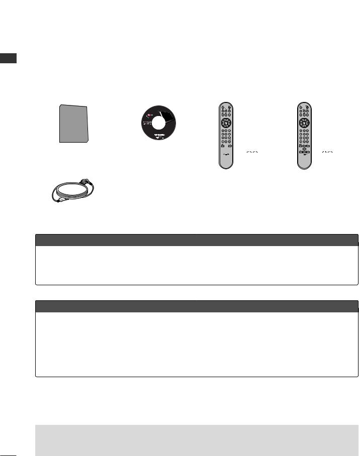
ACCESSORIES
Ensure that the following accessories are included with your product. If an accessory is missing, please contact the dealer where you purchased the product.
User must use shielded signal interface cables with ferrite cores to maintain standard compliance for the product.
|
|
|
|
|
|
|
|
|
|
|
|
|
|
|
|
|
|
|
|
|
|
|
|
|
|
|
|
|
|
Owner’s Manual |
CD Manual |
|
|
|
|
|
|
|
|
|
|
|
||
|
|
|
|
|
|
|
|
|
|
|
||||
|
|
|
|
|
|
|
|
|
|
|
||||
|
|
|
|
|
|
|
|
|
|
|
|
|
|
|
|
|
|
|
|
|
|
|
|
|
|
|
|
|
|
|
|
|
|
|
|
|
|
|
|
|
|
|
|
|
|
|
|
|
|
|
|
|
|
|
|
|
|
|
|
User Remote Control. |
Installer Remote Control. |
Batteries (Optional ) |
Batteries (Optional ) |
Power Cord
Optional User and Installer Remote Controls for Model No. 20LH1DC1
Shown herein is an optional remote control available for the 20LH1DC1 model only. The remote control is NOT included with the TV.
• However, both the User and Installer remotes can be purchased separately, see your LG dealer.
Purchase the Optional Installer's Remote and Clone Programmer
To perform a normal installation set up, you need an installer's remote and the LT2002 Quickset II Clone Programmer – both are shown and described in later sections. See your LG dealer if you wish to purchase the Installer remote and LT2002. The installer remote allows access to the Installer menus, User menus, and Channel Banks in the Manual Channel Set options on the Setup menu. The installer remote has Menu, Select, and Adjust Keys. The LT2002 Quickset II Clone Programmer is used to duplicate a TV's setup and install it on another identical TV.
 NOTE
NOTE
G Design and specifications are subject to change without prior notice.
6
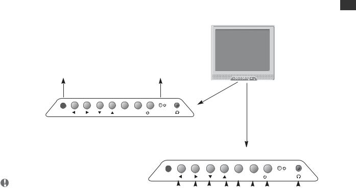
FRONT PANEL INFORMATION
■Here shown may be somewhat different from your TV.
■Using the front control panel to operate the TV.
Front Panel Controls
Remote Control Sensor
Power / Standby Indicator Glows red in Standby mode. Glows green when the TV is turned on.
Glows orange in Sleep Timer and/or Alarm mode.
VOL |
CH |
TV/AV MENU / I |
ATV Operation
Press the P OWER button to turn the TV
on from standby mode.
BPress M ENU repeatedly to scroll through
menus.
NOTE |
|
VOL |
|
CH |
TV/AV |
MENU |
|
/ I |
|
|
||||
|
|
|
|
|
|
|
|
|
|
|
|
|
|
|
G With Installer menu item 11 Key Defeat set to |
|
|
|
|
|
|
|
|
|
|
|
|
|
|
|
|
|
|
|
|
|
|
|
|
|
|
|
||
000 (the default setting), Menu and T V/AV |
|
|
|
|
|
|
|
|
|
|
|
|
|
|
buttons are disabled. |
|
E |
|
D |
C |
B |
A |
F |
||||||
|
|
|
|
|
|
|
|
|
|
|
|
|
|
|
CDisplays the current channel bank. Press again to change banks.
PREPARATION
D
E
Use the C H (Channel) D or E button to cycle through the available channels.
Use the V O L (Volume) F or G button to adjust the sound level to your preference.
FInsert the headphone plug to the headphone socket of the set.
On-Screen Displays
See descriptions on page 21. On-screen displays will appear when the feature is active or the function is being used.
LED Color |
Action/Status |
|
|
|
|
|
|
|
|
||
RED |
Power is Off (Standby) |
|
|
||
|
|
|
|
||
GREEN is flashing |
Power On sequence is processing |
|
|
||
|
|
|
|
|
|
GREEN |
Power is On |
|
|
|
|
|
|
|
|
|
|
ORANGE |
If Power is Off |
On Timer is set or Alarm is set |
|
|
|
7 |
|||||
|
|
|
|
||
|
If Power is On |
Off Timer is set or Sleep Timer is set |
|
||
PREPARATION
PREPARATION
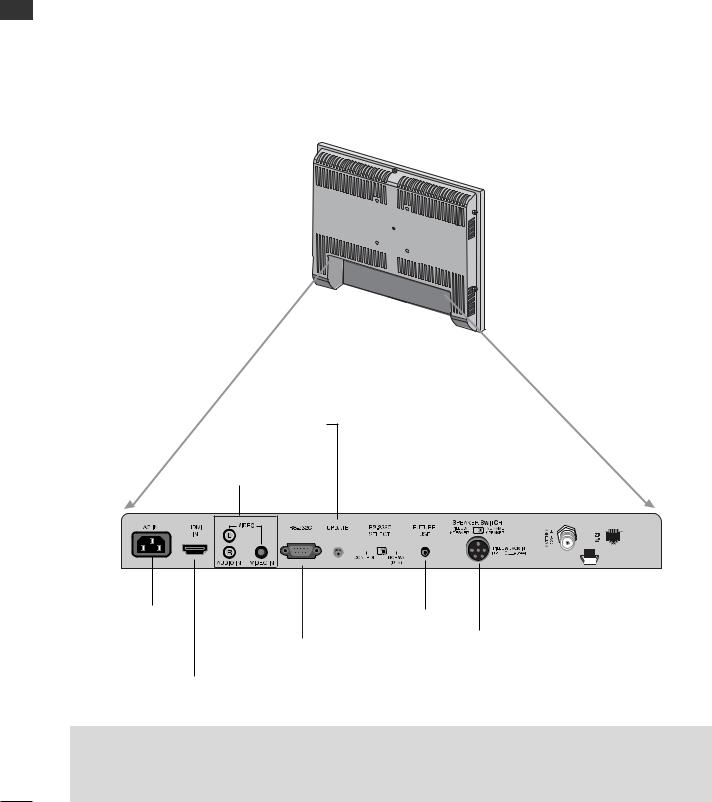
BACK PANEL INFORMATION
■ Here shown may be somewhat different from your TV.
Back Connection Panel
UPDATE SWITCH
AUDIO / VIDEO IN
Connect Audio / Video equipment to these jacks.
SPEAKER SWITCH
Used to select the speaker output switch.
*Note: If Pillow Speaker is selected, no Sound will be heard from TV speakers.
(NORMAL SPEAKER or PILLOW SPEAKER.)
|
|
|
RS-232C |
|
|
M.P.I. INTERFACE |
|||||||||||
|
|
|
|
|
|
Use with clone |
|||||||||||
SELECT SWITCH |
|
|
|
||||||||||||||
|
|
|
|
programmer. |
|||||||||||||
|
|
|
|
|
|
|
|
|
|
||||||||
|
|
|
|
|
|
|
|
|
|
||||||||
|
|
|
|
|
|
|
|
|
|
|
|
|
|
|
|
|
|
|
|
|
|
|
|
|
|
|
|
|
|
|
|
|
|
|
|
|
|
|
|
|
|
|
|
|
|
|
|
|
|
|
|
|
|
|
|
|
|
|
|
|
|
|
|
|
|
|
|
|
|
|
|
|
|
|
|
|
|
|
|
|
|
|
|
|
|
|
|
|
|
|
|
|
|
|
|
|
|
|
|
|
|
|
|
|
|
|
|
|
|
|
|
|
|
|
|
|
|
|
|
|
|
|
|
|
|
|
|
|
|
|
|
|
|
|
|
|
|
|
|
|
|
|
|
ANTENNA CABLE
AC IN FUTURE USE Connect to an antenna or cable system.
RS-232C PORT
PILLOW JACK IN
Used to connect to pillow speaker
(12V DC  40mA)
40mA)
HDMI IN
 NOTE
NOTE
GRS-232C, Update Switch and RS-232C Select Switch are reserved for qualified and authorized service and technical support personal only.
8
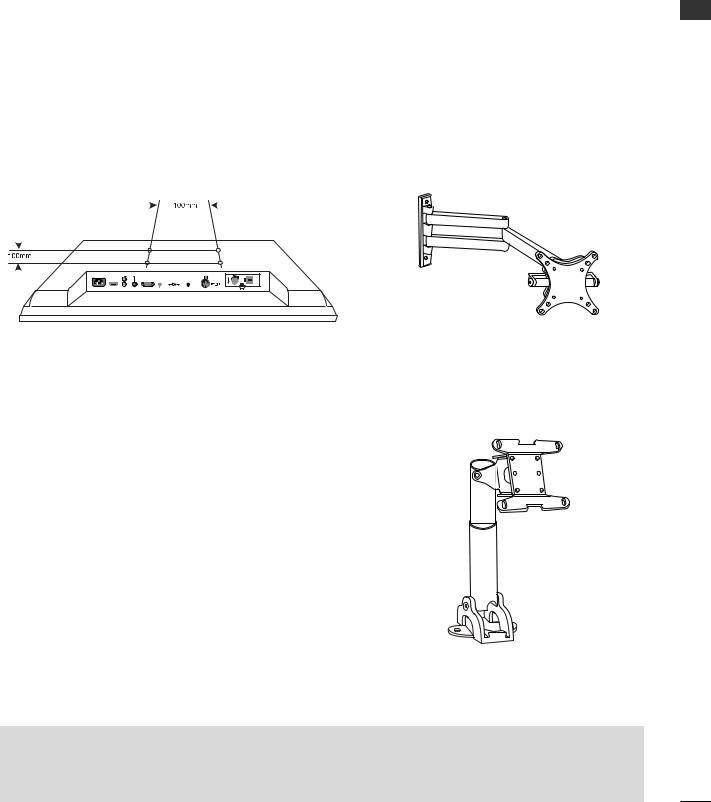
VESA WALL MOUNTING
■ Here shown may be somewhat different from your TV.
Following are shown some examples of VESA standard 100mm mounts. Since there are numerous types of stands and mounts available, only a few are shown here. Refer to the instructions provided with the TV stand that will be used to mount the TV.
General Guidelines: Choosing a location for |
Typical Wall Stud Type Mount with |
installing a VESA Standard Mount |
Swivel Bracket |
PREPARATION
AC IN |
|
VIDEO |
|
|
|
|
SPEAKER SWITCH |
HDMI |
RS-232C |
UPDATE |
RS-232C |
FUTURE |
|||
|
IN |
L |
|
|
SELECT |
USE |
|
|
|
R |
|
|
CONTROL |
NORMAL |
|
|
|
AUDIO IN VIDEO IN |
|
|
|
(DTV) |
|
Be sure the style of stand selected is capable of supporting the weight of the TV.
If the mount will be on a wall, a typical wooden stud behind the wall board would be the preferred choice for a location to attach the wall mount. The wall mount location chosen should be appro-priate for drilling holes and have available the required power source as well as antenna/cable and other equipment leads.
For pedestal-type mounts, a sturdy surface on a desk or other similar flat table-like surface would be the appropriate location for mounting a pedestal-style TV stand. (Some stands are portable and can be moved from one location to another.) Be sure all safety considerations are followed.
Most stands are designed so that the wiring would be threaded through the stand itself or a loop-through style clamp so that the wiring is neatly bunched and not strung in such a way as to create a potential hazard to the user.
Typical Pedestal Type Mount with Swivel Bracket
 NOTE
NOTE
G Screw length needed depends on the wall mount used. For further information, refer to the VESA Wall Mounting Instruction Guide.
9
EXTERNAL EQUIPMENT SETUP
SETUP EQUIPMENT EXTERNAL
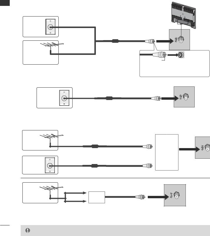
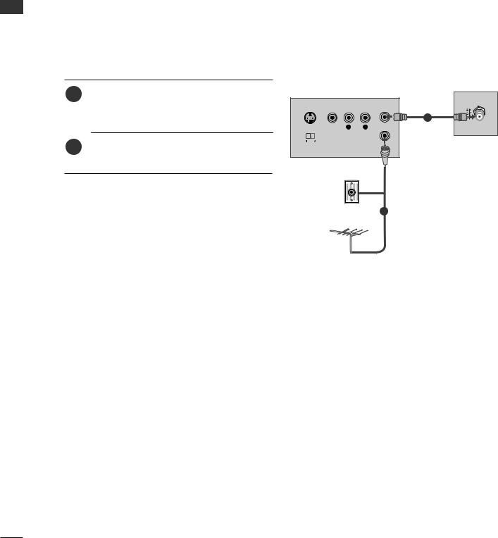
ANTENNA OR CABLE CONNECTION
1. Antenna (Analog or Digital)
Wall Antenna Socket or Outdoor Antenna without a Cable Box Connections.
For optimum picture quality, adjust antenna direction if needed.
Wall |
Multi-family Dwellings/Apartments |
|
(Connect to wall antenna socket) |
|
|
Antenna |
|
|
Socket |
|
|
Outdoor |
RF Coaxial Wire (75 ohm) |
|
|
|
|
Antenna |
|
|
(VHF, UHF) |
Single-family Dwellings /Houses |
Copper Wire |
|
(Connect to wall jack for outdoor antenna) |
|
|
|
Be careful not to bend the bronze wire when connecting the antenna.
2. Cable
Cable TV
Wall Jack
RF Coaxial Wire (75 ohm)
3. Using both cable and antenna
Antenna
RF Coaxial Wire (75 ohm)
Cable TV
Wall Jack
RF Coaxial Wire (75 ohm)
|
UHF |
Antenna |
Signal |
|
Amplifier |
|
VHF |
Diplexer
(Signal
Combiner)
■To improve the picture quality in a poor signal area, please purchase a signal amplifier and install properly.
■If the antenna needs to be split for two TV’s, install a 2-Way Signal Splitter.
■If the antenna is not installed properly, contact your dealer for assistance.
NOTE G The TV will let you know when the analog, cable, and digital channel scans are complete.
10
■To prevent the equipment damage, never plug in any power cords until you have finished connecting all equipment.
HD RECEIVER SETUP
This TV can receive Digital Over-the-air/Cable signals without an external digital set-top box. However, if you do receive digital signals from a digital set-top box or other digital external device, refer to the figure as shown below.
When connecting HDMI cable
1. How to connect
1 |
Connect the digital set-top box to HDMI IN jack on the |
|
|
|
|
|
|
|
|
|
|
|
|
|
|
|
|
|
|
|
|
|
|
|
|
|
VIDEO |
||||||||||||
|
AC IN |
||||||||||||||||||
|
HDMI |
|
|
|
|
|
|
|
|
||||||||||
|
|
|
|
||||||||||||||||
set. |
|
|
|
|
|
|
|
|
|
|
|
|
|
||||||
|
|
|
|
|
|
|
|
|
|
L |
|
|
|||||||
|
|
|
|
|
|
|
|
|
|
|
|
||||||||
|
|
|
|
|
|
|
|
|
|
||||||||||
|
|
|
|
|
|
|
|
|
|
|
|
|
|
|
|
|
|
|
|
|
|
|
|
|
|
|
|
|
|
|
|
|
|
||||||
|
|
|
|
|
|
|
|
|
|
|
R |
|
|||||||
|
necessary. |
|
|
|
|
|
|
|
|
|
|
|
|
|
|
|
|
||
|
|
|
|
|
|
|
|
AUDIO IN |
VIDEO IN |
||||||||||
|
|
|
|
|
|
|
|
|
|
|
|
|
|
||||||
|
|
|
|
|
|
|
|
|
|
|
|
|
|
|
|
|
|
|
|
2. |
1 |
|
|
|
Turn on the digital set-top box. |
|
(Refer to the owner’s manual for the digital set-top box.) |
Select H DMI input source by using the 1 - 3 - 3 buttons |
|
on the remote control. (Refer to p.65) |
HDMI-DTV OUTPUT |
 NOTE
NOTE
G When connected, the TV will tell a connected device what resolution it supports and the resolution it prefers. If the device supports this Auto HDMI function, the player output resolution will be automatically set to 720p.
G If the device does not support Auto HDMI, you need to set the output resolution appropriately.
SETUP EQUIPMENT EXTERNAL
11
EXTERNAL EQUIPMENT SETUP
SETUP EQUIPMENT EXTERNAL
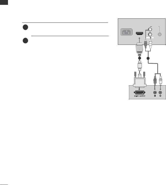
When connecting HDMI to DVI cable
1. How to connect
|
1 Connect the DVI output of the digital set-top box to the |
|
|
|
|
|
|
|
|
|
|
|
|
VIDEO |
|
|
|||
|
|
|
AC IN |
|
HDMI |
|
|
|
|
|
|
|
|
|
|
|
|||
|
|
|
|
|
|
|
|
|
|
|
|
|
|
|
|||||
|
HDMI IN jack on the set. |
|
|
|
|
|
|
|
L |
||||||||||
|
|
|
|
|
|
|
|
|
|
|
|
|
|
|
|
|
|
||
|
|
|
|
|
|
|
|
|
|
|
|
|
|
|
|
|
|||
|
|
|
|
|
|
|
|
|
|
|
|
|
|
||||||
|
|
|
|
|
|
|
|
|
|
|
R |
|
|||||||
|
|
|
|
|
|
|
|
|
|
|
|
|
|
|
|
|
|
|
|
|
audio output of the digital set-top box to |
|
|
|
|
|
|
AUDIO IN |
VIDEO IN |
||||||||||
|
|
|
|
|
|
|
|
|
|
|
|
|
|
|
|
|
|
||
|
O IN jack on the set. |
|
|
|
|
|
|
|
|
|
|
|
|
|
|
|
|
|
|
2. |
|
|
|
|
1 |
|
2 |
|
|
|
|
|
|
|
|
|
|||
|
|
|
|
|
|
|
|
|
|
|
|
|
|
||||||
|
|
|
|
|
|
|
|
|
|
|
|
|
|
|
|
|
|
|
|
■Turn on the digital set-top box. (Refer to the owner’s manual for the digital set-top box.)
■ Select HDMI input source by using the 1 - 3 - 3 buttons on the remote control. (Refer to p.65)
12
DVD SETUP
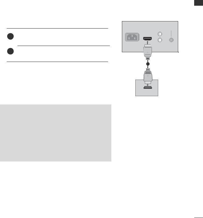
When connecting HDMI cable
1. How to connect
1Connect the HDMI output of the DVD to the HDMI IN jack on the set.
audio connection is necessary. both audio and video.
2.to use
■Select HDMI input source by using the 1 - 3 - 3 buttons on the remote control. (Refer to p.65)
■Refer to the DVD player's manual for operating instructions.
AC IN |
|
HDMI |
|
|
|
|
|
VIDEO |
|
|
||||
|
|
|
|
|
|
|
|
|
|
|
||||
|
|
|
|
|
|
|
|
|
||||||
|
|
|
IN |
|
|
L |
|
|||||||
|
|
|
|
|
|
|
||||||||
|
|
|
|
|
|
|
|
|
|
|
|
|
|
|
|
|
|
|
|
|
|
|
|
|
|
|
|
|
|
|
|
|
|
|
|
|
|
|
|
|||||
|
|
|
|
|
|
|
|
R |
||||||
|
|
|
|
|
|
|
|
|
|
|
|
|
||
|
|
|
|
|
|
AUDIO IN |
VIDEO IN |
|||||||
1
HDMIOUTPUT
 NOTE
NOTE
G When connected, the TV will tell a connected device what resolution it supports and the resolution it prefers. If the device supports this Auto HDMI function, the player output resolution will be automatically set to 720p.
G If the device does not support Auto HDMI, you need to set the output resolution appropriately.
To get the best picture quality, adjust the output resolution of the DVD to 720p.
SETUP EQUIPMENT EXTERNAL
13
EXTERNAL EQUIPMENT SETUP
SETUP EQUIPMENT EXTERNAL
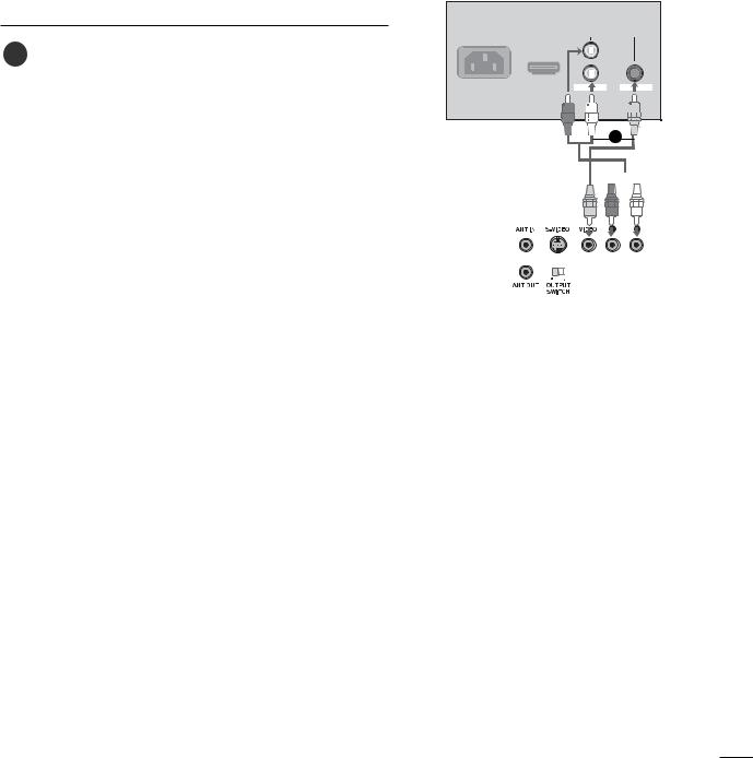
VCR SETUP
■To avoid picture noise (interference), leave an adequate distance between the VCR and TV.
■If the 4:3 picture format is used; the fixed images on the sides of the screen may remain visible on the screen. This phenomenon is common to all manufactures and in consequence the manufactures warranty does not cover the product bearing this phenomenon.
When connecting with an antenna
1.How to connect
1 Connect the RF antenna out socket of the VCR to the ANTENNA/CABLE socket on
the set.
the antenna cable to the RF
socket of the VCR.
1
S-VIDEO VIDEO |
L |
R |
|||
|
|
|
|
|
|
|
|
|
|
|
|
OUTPUT
SWITCH
Wall Jack
2.to use
■Set VCR output switch to 3 or 4 and then tune TV to the same channel number.
■Insert a video tape into the VCR and press PLAY on the VCR. (Refer to the VCR owner’s manual.)
2
Antenna
14
When connecting with a RCA cable
1. How to connect
1 |
een TV and VCR. Match |
|
Audio Left = white, and |
||
|
||
|
Audio Right = red) |
|
|
|
2.to use
a video tape into the VCR and press PLAY on the
. (Refer to the VCR owner’s manual.)
A V input source by using the 1 - 3 - 1 buttons on remote control. (Refer to p.65)
|
|
|
|
|
|
|
|
|
|
|
|
|
|
|
|
|
|
|
|
|
|
|
|
|
|
|
|
|
|
|
|
|
|
|
|
|
|
|
|
|
|
|
EXTERNAL |
|
|
|
|
|
|
|
|
|
|
|
|
|
VIDEO |
|
|
|
|
||||
AC IN |
|
|
HDMI |
|
|
|
|
|
|
|
|
|
|
|
|
|
|
|
EQUIPMENT |
||
|
|
|
|
|
|
|
|
|
|
|
|
|
|
|
|
|
|
|
|
|
|
|
|
|
|
IN |
|
|
|
|
L |
|
|
|
|||||||||
|
|
|
|
|
|
||||||||||||||||
|
|
|
|
|
|
|
|
|
|
|
|
|
|
|
|
|
|
|
|
|
|
|
|
|
|
|
|
|
|
|
|
|
|
|
|
|
|
|
|
|
|
|
|
|
|
|
|
|
|
|
|
|
|
|
|
|
|
|
|
|
|
|
|||
|
|
|
|
|
|
|
|
|
R |
|
|
|
|
|
|
|
|||||
|
|
|
|
|
|
|
|
|
|
|
|
|
|
|
|
|
|
|
|
|
|
|
|
|
|
|
|
|
|
AUDIO IN |
VIDEO IN |
|
|||||||||||
|
|
|
|
|
|
|
1 |
|
|
|
|
|
SETUP |
||||||||
|
|
|
|
|
|
|
|
|
|
|
|
|
|
|
|
|
|
|
|
|
|
|
|
|
|
|
|
|
|
|
|
|
|
|
|
|
|
|
|
|
|
|
|
|
|
|
|
|
|
|
|
|
|
|
|
|
|
|
|
|
|
|
|
|
|
|
|
|
|
|
|
|
|
|
|
|
|
|
|
|
|
|
|
|
|
|
|
|
|
|
|
|
|
|
|
|
|
|
|
|
|
|
|
|
|
|
|
|
|
|
|
|
|
|
|
|
|
|
|
|
|
|
|
|
|
|
|
|
|
|
|
15
EXTERNAL EQUIPMENT SETUP
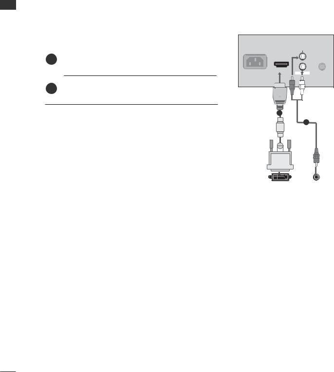
PC SETUP
When connecting HDMI to DVI cable
EXTERNAL |
1. How to connect |
|||
|
||||
SETUPEQUIPMENT |
|
|
|
|
1 |
Connect the DVI output of the PC to the HDMI IN |
|||
jack on the set. |
||||
|
||||
|
|
|
||
O IN jack on
2.to use
urn on the PC and the TV.
H DMI input source by using the 1 - 3 - 3 on the remote control. (Refer to p.65)
AC IN |
|
|
|
|
|
|
|
|
|
|
VIDEO |
|
||||
|
HDMI |
|
||||||||||||||
|
|
|
|
|
|
|
|
|
|
|
|
|
||||
|
|
|
|
|
|
|
|
|
|
|
||||||
|
|
|
IN |
|||||||||||||
|
|
|
|
|
L |
|||||||||||
|
|
|
|
|||||||||||||
|
|
|
|
|
|
|
|
|
|
|
|
|
|
|
||
|
|
|
|
|
|
|
|
|
|
|
|
|
|
|
||
|
|
|
|
|
|
|
|
|
|
|||||||
|
|
|
|
|
|
|
|
R |
||||||||
|
|
|
|
|
|
|
|
|
|
|
|
|
|
|
|
|
|
|
|
|
|
|
AUDIO IN |
VIDEO IN |
|||||||||
1
2
|
|
|
|
|
|
|
|
|
|
|
|
|
|
|
|
|
|
|
|
|
|
|
|
DVI-PC-OUTPUT |
AUDIO |
||||||
|
|
|
|
|
|
|
|
16

 NOTE
NOTE
G To get the the best picture quality, adjust the PC graphics card to 1024x768, 60Hz.
G Depending on the graphics card, DOS mode may not work if a HDMI to DVI Cable is in use.
G Check the image on your TV. There may be noise associated with the resolution, vertical pattern, contrast or brightness in PC mode. If noise is present, change the PC output to another resolution, change the refresh rate to another rate or adjust the brightness and contrast on the
VIDEO menu until the picture is clear. If the refresh rate of the PC graphic card can not be changed, change the PC graphic card or consult the manufacturer of the PC graphic card.
G Avoid keeping a fixed image on the screen for a long period of time. The fixed image may become permanently imprinted on the screen.
G The synchronization input form for Horizontal and Vertical frequencies is separate.
Supported Display Specifications
HDMI/DVI-PC mode |
|
|
HDMI/DVI-DTV mode |
|
||
|
|
|
|
|
|
|
Resolution |
Horizontal |
Vertical |
|
Resolution |
Horizontal |
Vertical |
Frequency(KHz) |
Frequency(Hz) |
|
Frequency(KHz) |
Frequency(Hz) |
||
|
|
|
||||
|
|
|
|
|
|
|
640x480 |
31.469 |
59.94 |
|
720x480p |
31.469 |
59.94 |
|
|
|
|
31.500 |
60.00 |
|
800x600 |
|
|
|
|
||
37.879 |
60.31 |
|
|
|
|
|
1024x768 |
|
|
|
1280x720p |
44.960 |
59.94 |
48.363 |
60.00 |
|
45.000 |
60.00 |
||
|
|
|||||
1280x768 |
47.776 |
59.87 |
|
1920x1080i |
33.720 |
59.94 |
|
|
|
|
33.750 |
60.00 |
|
1360x768 |
|
|
|
|
||
47.720 |
59.799 |
|
|
|
|
|
|
|
|
|
|||
1366x768 |
47.130 |
59.65 |
|
|
|
|
|
|
|
|
|
|
|
|
|
|
|
|
|
|
SETUP EQUIPMENT EXTERNAL
17
EXTERNAL EQUIPMENT SETUP
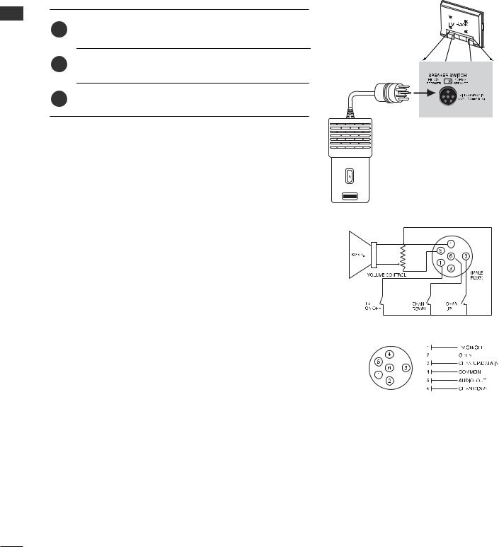
PILLOW SPEAKER SETUP
■ Here shown may be somewhat different from your TV.
SETUP EQUIPMENT EXTERNAL
1. How to connect
1 |
JACK IN the Pillow Speaker output |
TV. |
speaker or wired remote
2
3
*Note: If the pillow Speaker switch is set to Pillow Speaker, no sound will be heard from the TV speakers. If pillow speaker switch is set to the Pillow Speaker position, Auto Volume will be grayed out and not accessible on the Sound menu.
Use a pillow speaker by Curbell, Model A-16455-02 or other UL recognized pendant control bearing the warning: “Risk of fire if used in oxygen enriched atmosphere.
Keep pendant control away from oxygen equipment.”
Pillow speaker not included with TV.
Controlling the TV with Serial Data
The TV is capable of being controlled by a single-wire,
serial data signal. This is a LG patented technology and is being implemented by certain brands of “smart” pillow speakers, such as Curbell’s “GEN-II” models.
Pillow Speaker Interface
This connector furnishes three control lines and an audio output. A patient-pendant remote control, or entertainment audio and nurse call system may be connected here. All lines are isolated from the AC power line and earth ground. (Opto-isolators isolate the control lines, and a transformer isolates the audio. There are no relays or inductive components in the control lines.)
|
|
|
|
|
Pin No. |
Purpose |
|
|
|
|
|
|
1 |
External TV On/Off switch. |
|
|
|
|
|
|
2 |
(Not used.) |
|
|
3 |
External Channel Up switch or Data in. |
|
|
|
|
|
|
4 |
Common connection for control, data, and audio output. |
|
|
|
Impedance to earth ground is a 10-meg resistor in parallel |
|
|
|
with a 1100 pf capacitor. |
|
|
|
|
|
|
5 |
Isolated audio output. Nominal 14-ohm source impedance |
|
|
|
with short circuit protection. Intended for a pillow speaker |
|
|
|
with a low-impedance pad-type volume control. |
|
|
|
|
|
|
6 |
External Channel Down switch. |
|
|
|
|
|
|
|
|
|
Controlling the TV with Mechanical Switches
Pin 4 (common) is momentarily connected to pin 1, 3, or 6 via push-action switches to control On/Off and Channel Up/Down. These pins are at +13 volts DC (when measured from pin 4) with the switches open. Current draw is 8mA when a switch is closed. (This operation is identical to previous LG models using the 5-Wire Interface except that only +7 volts DC was supplied and current draw was only 2.5 mA.)
18
WATCHING TV /CHANNEL CONTROL
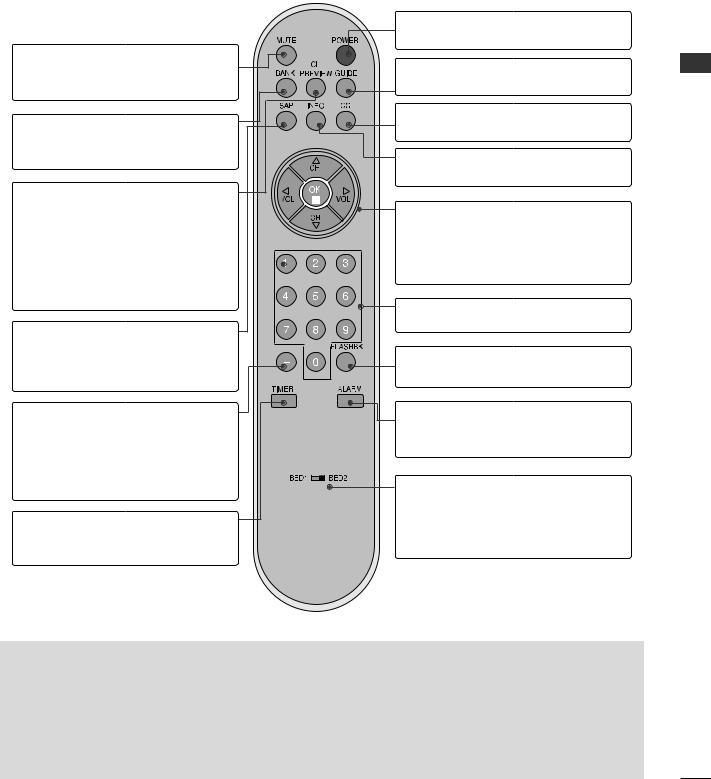
USER REMOTE CONTROL BUTTON FUNCTIONS
A brief list of the buttons on the optional patient remote control and what they do.
MUTE
Turns sound Off and On, while the picture remains.
BANK
Press and repeat to select a Channel
Memory Bank - - 1, 2, 3, or 4 (Standby).
CHANNEL PREVIEW
Displays available TV channels, and (if active) the Guest Parental Control menu: set V-Chip blocks to restrict both analog and digital programming.
• Aux Channel allows the guest to select the Audio / Video inputs. (Use the A/V jacks on the back of the TV as a source).
SAP
Selects MTS sound: Mono, Stereo, and SAP in analog mode. Change the audio language in DTV mode.
[-] BUTTON
When selecting a digital broadcast channel, key in the Main channel number followed by the -> [-] -> then the sub channel number. Analog channels do not contain a sub channel number.
Optional Patient
Control
 NOTE
NOTE
POWER
Turns TV On or Off.
GUIDE
Use to view DTV program information.
CC (Closed Captioning)
Press to access closed captions.
CHANNEL / OK (Enter) decrease sound level.
channels.
screen menu items and change
G Bed 1 - Bed 2 switch on patient remote. The position of the Bed 1 - Bed 2 switch must correspond to the setting in the Installer’s menu. The switch above can be set by sliding it to the Bed 1 or Bed 2 position. On the patient’s remote, the Bed 1 or Bed 2 position can be selected by using a paper clip or a ball-point pen to slide the switch to the correct position.
Left position = Bed 1. Right Position = Bed 2.
CONTROL CHANNEL / TV WATCHING
19

WATCHING TV /CHANNEL CONTROL
INSTALLER REMOTE CONTROL BUTTON FUNCTIONS
CONTROL CHANNEL / TV WATCHING
A brief list of the buttons on the optional installer remote and what they do.
MUTE
Turns sound Off and On, while the picture remains.
BANK
Press and repeat to select a Channel Memory Bank - - 1, 2, 3 or 4 (Standby).
SAP
Selects MTS sound: Mono, Stereo, and SAP in analog mode. Change the audio language in DTV mode.
[-] BUTTON
When selecting a digital broadcast channel, key in the Main channel number followed by the -> [-] -> then the sub channel number. Analog channels do not contain a sub channel number.
MENU
Press to display the main on-screen menu.
POWER
Turns TV On or Off.
GUIDE
Use to view DTV program information.
CC (Closed Captioning)
Press to access closed captions.
CHANNEL / OK (Enter) decrease sound level.
channels.
screen menu items and change menu values.
Optional Installer
Remote Control
 NOTE
NOTE
G Bed 1 - Bed 2 switch on patient remote. The position of the Bed 1 - Bed 2 switch must correspond to the setting in the Installer’s menu. The switch above can be set by sliding it to the Bed 1 or Bed 2 position. On the patient’s remote, the Bed 1 or Bed 2 position can be selected by using a paper clip or a ball-point pen to slide the switch to the correct position.
Left position = Bed 1. Right Position = Bed 2.
20
ON-SCREEN MENUS SELECTION
Use the remote keys indicated below to access these menus and displays.
In this manual, the OSD (On Screen Displays shown) may be different. The following are just generic examples to familiarize you with the TVs options.
19
Volume Display
Press VOLUME.
Shows currently selected sound setting.
F  CAPTION Service1 G
Caption Display
Press the CC.
Turns selected option on or off. See Closed Captions page to select options.
12 |
|
TIMER |
Off |
6 |
3 |
||
9 |
|
|
|
Sleep Timer Menu
Press TIMER.
Sets a time to automatically turn the TV off and shows remaining time before TV shutoff.
Alarm Timer
Current Time 11:17 AM
|
Hr. |
Min. |
|
Off |
|
Move |
Adjust |
OK Exit |
Alarm Display
Press the ALARM.
Set a time for the TV to turn itself on.
F |
SAP English G |
SAP Display
Selects MTS sound: Mono, Stereo, and SAP in analog mode. Change the audio language in DTV mode.
Guide Display
Press the GUIDE to view DTV program information.
CONTROL CHANNEL / TV WATCHING
|
|
|
|
|
|
|
|
|
|
|
|
|
|
|
|
|
|
|
|
|
|
|
|
|
|
|
|
|
|
|
|
|
|
|
|
|
|
|
|
|
|
|
|
|
|
|
|
|
|
|
|
|
|
|
|
|
|
|
|
|
|
|
|
|
|
|
|
|
|
|
|
|
|
|
|
|
|
|
|
|
|
|
|
|
|
|
|
|
|
|
|
|
|
|
|
|
|
|
|
|
|
|
|
|
|
|
|
|
|
|
|
|
|
|
|
|
|
|
|
|
|
|
|
|
|
|
|
|
|
|
|
|
|
|
|
|
|
|
|
|
|
|
|
|
|
|
|
|
|
|
|
|
|
|
|
|
|
|
|
|
|
|
|
|
|
|
|
|
|
|
|
|
|
|
|
|
|
|
|
|
|
|
|
|
|
|
|
|
|
|
|
|
|
|
|
|
|
|
|
|
|
|
|
|
|
|
|
|
|
|
|
|
|
|
|
|
|
|
|
|
|
|
|
|
|
|
|
|
|
|
|
|
|
|
|
|
|
|
|
|
|
|
Channel Preview |
|
|
|
|
V-Chip |
|
|
|
|
INFO |
||||||
Press the CH PREVIEW. |
|
|
|
Press the CC. |
|
|
Press the INFO. |
||||||||||||
Displays available TV channels. |
|
|
|
Move to the V-Chip menu. |
|
|
Check the current program |
||||||||||||
|
|
|
|
|
|
|
|
|
|
|
|
|
|
|
|
|
information. |
||
|
|
|
|
|
|
|
|
|
|
|
|
|
|
|
|
||||
|
|
|
|
|
|
|
|
|
|
|
|
|
|
|
|
|
|
|
|
21

WATCHING TV /CHANNEL CONTROL
CHANNEL SEARCH
Auto Program (Channel Search)
Use Auto Program to automatically find and store all of the channels available in the selected Tuning Band.
|
|
|
NOTE |
|
/ TV WATCHING |
|
|
||
|
G Tuning Band must be set before doing the channel |
|||
|
|
search. See Installer menu item 003 Band/AFC. Default |
||
|
|
setting is 1, for CATV. When Auto Program is run, any |
||
|
|
assigned channel labels are automatically removed. |
||
|
|
|
||
|
|
|
||
1 |
in hand and |
|||
CHANNEL |
press the POWER button to turn the TV on. |
|||
|
|
|||
|
|
|
||
2 |
on and then use the A DJ D or E |
|||
|
|
|
Channel menu and press the |
|
CONTROL |
|
|
OK (Enter) button. |
|
3 |
nter) button to highlight |
|||
|
||||
|
4 |
the O K (Enter) button to start the channel |
||
|
|
|
. |
|
|
|
|
After finding all available channels, a display appears |
|
|
|
|
briefly showing the number of analog and digital channels |
|
|
|
|
found. |
|
|
|
|
|
|
|
5 |
finished, press M ENU repeatedly to remove the |
||
|
|
|
|
|
Antenna |
|
|
Auto Program |
|
G |
Channel Label |
|
|
Channel List |
|
|
Fine Tune |
Auto |
|
Signal Strength |
|
|
--:-- -- |
|
|
--. -- ---- |
|
|
D E Move |
OK Select |
MENU Back |
Antenna
Auto Program
Press OK to Search
Channel Label
Channel List
Yes
Fine Tune
Signal Strength
--:-- --
--. -- ----
F G Move |
OK Select |
MENU Back |
Antenna
Channel Label
Channel List
--:-- --
--. -- ----
MENU Back
 NOTE
NOTE
G Auto Program finds channels being received by the TV’s analog and digital tuners.
G Cable will not work unless you subscribe to a cable service.
22

Channel List
After the channel search, remove unwanted channels.
1 |
tton and then use the A DJ D or E |
|
Channel menu and press the |
|
OK (Enter) button. |
|
|
2 |
highlight Channel List |
3 |
the channel |
|
button. |
|
The A DJ G button toggles the check mark on and off. |
|
If the check mark appears next to the channel number, |
|
the channel appears in the channel scan. |
|
|
4 |
finished, press M ENU repeatedly to remove the |
|
|
Antenna |
|
|
Auto Program |
|
|
Channel Label |
|
|
Channel List |
|
G |
Fine Tune |
Auto |
|
Signal Strength |
|
|
--:-- -- |
|
|
--. -- ---- |
|
|
D E Move |
OK Select |
MENU Back |
--:-- --
--. -- ----
Antenna |
|
|
|
|
|
Auto Program |
|
|
|
|
|
Channel Label |
|
|
|
|
|
Channel List |
|
|
|
|
|
Fine Tune |
|
|
|
|
|
Signal Strength |
|
|
|
|
|
D E Move |
G Add/Del |
OK |
View |
MENU |
Back |
CONTROL CHANNEL / TV WATCHING
 NOTE
NOTE
G If you delete a found channel, it isn’t gone forever. Simply re-enter the Channel List menu and re-add the channel to show the check mark.
23
Loading...