


 Loading...
LexmarkTM W820, X820e, X830e, X832e
Printers
4025-XXX
•Table of Contents
•Start Diagnostics
•Safety and Notices
•Trademarks
•Index
•Manuals Menu
Lexmark and Lexmark with diamond design are trademarks of Lexmark International, Inc., registered in the United States and/or other countries.
Edition: March 24, 2006
The following paragraph does not apply to any country where such provisions are inconsistent with local law: LEXMARK INTERNATIONAL, INC. PROVIDES THIS PUBLICATION “AS IS” WITHOUT WARRANTY OF ANY KIND, EITHER EXPRESS OR IMPLIED, INCLUDING, BUT NOT LIMITED TO, THE IMPLIED WARRANTIES OF MERCHANTABILITY OR FITNESS FOR A PARTICULAR PURPOSE. Some states do not allow disclaimer of express or implied warranties in certain transactions; therefore, this statement may not apply to you.
This publication could include technical inaccuracies or typographical errors. Changes are periodically made to the information herein; these changes will be incorporated in later editions. Improvements or changes in the products or the programs described may be made at any time.
Comments may be addressed to Lexmark International, Inc., Department D22A/032-2, 740 West New Circle Road, Lexington, Kentucky 40550, U.S.A or e-mail at ServiceInfoAndTraining@Lexmark.com. Lexmark may use or distribute any of the information you supply in any way it believes appropriate without incurring any obligation to you.
Lexmark and Lexmark with diamond design are trademarks of Lexmark International, Inc., registered in the United States and/or other countries.
PostScript is a registered trademark of Adobe Systems Incorporated.
Other trademarks are the property of their respective owners.
©Copyright Lexmark International, Inc. 2001, 2005. All rights reserved.
UNITED STATES GOVERNMENT RESTRICTED RIGHTS
This software and documentation are provided with RESTRICTED RIGHTS. Use, duplication or disclosure by the Government is subject to restrictions as set forth in subparagraph (c)(1)(ii) of the Rights in Technical Data and Computer Software clause at DFARS 252.227-7013 and in applicable FAR provisions: Lexmark International, Inc., Lexington, KY
U.S.A. P/N 12G9449

4025-XXX
Table of Contents
Notices and Safety Information . . . . . . . . . . . . . . . . . . . . . . . . . . . . . . . . . . . . . . . . . . . . . . |
ix |
Laser Advisory and Caution Labels . . . . . . . . . . . . . . . . . . . . . . . . . . . . . . . . . . |
ix |
Class 1 Laser Statement Label . . . . . . . . . . . . . . . . . . . . . . . . . . . . . . . . . . . . . . |
. x |
Laser Notices . . . . . . . . . . . . . . . . . . . . . . . . . . . . . . . . . . . . . . . . . . . . . . . . . . . . . . |
xi |
Safety Information . . . . . . . . . . . . . . . . . . . . . . . . . . . . . . . . . . . . . . . . . . . . . . . . . . |
xiv |
Preface . . . . . . . . . . . . . . . . . . . . . . . . . . . . . . . . . . . . . . . . . . . . . . . . . . . . . . . . . . . . . . . . . . . . . . . . . xvii
General Information. . . . . . . . . . . . . . . . . . . . . . . . . . . . . . . . . . . . . . . . . . . . . . . . . . . . . . . . . . . 1-1
Options . . . . . . . . . . . . . . . . . . . . . . . . . . . . . . . . . . . . . . . . . . . . . . . . . . . . . . . . . . 1-1
Maintenance Approach . . . . . . . . . . . . . . . . . . . . . . . . . . . . . . . . . . . . . . . . . . . . . 1-1
Tools Required For Service . . . . . . . . . . . . . . . . . . . . . . . . . . . . . . . . . . . . . . . . . . 1-1
Serial Number Locations . . . . . . . . . . . . . . . . . . . . . . . . . . . . . . . . . . . . . . . . . . . . 1-2
Symbols Used in this Manual . . . . . . . . . . . . . . . . . . . . . . . . . . . . . . . . . . . . . . . . 1-3
Safety Details . . . . . . . . . . . . . . . . . . . . . . . . . . . . . . . . . . . . . . . . . . . . . . . . . . . . . 1-3
Power Supply and Electrical Components . . . . . . . . . . . . . . . . . . . . . . . . . . . . 1-3
Mechanical Components . . . . . . . . . . . . . . . . . . . . . . . . . . . . . . . . . . . . . . . . . . 1-4
Laser Components . . . . . . . . . . . . . . . . . . . . . . . . . . . . . . . . . . . . . . . . . . . . . . 1-4
Fuser Components . . . . . . . . . . . . . . . . . . . . . . . . . . . . . . . . . . . . . . . . . . . . . . 1-4
Safety Components . . . . . . . . . . . . . . . . . . . . . . . . . . . . . . . . . . . . . . . . . . . . . . 1-4
Caution Labels . . . . . . . . . . . . . . . . . . . . . . . . . . . . . . . . . . . . . . . . . . . . . . . . . 1-5
Service Flowchart . . . . . . . . . . . . . . . . . . . . . . . . . . . . . . . . . . . . . . . . . . . . . . . . . . 1-5
Printer Overview . . . . . . . . . . . . . . . . . . . . . . . . . . . . . . . . . . . . . . . . . . . . . . . . . . . 1-6
Schematic Diagram of Printer Operation . . . . . . . . . . . . . . . . . . . . . . . . . . . . . |
1-7 |
Printer Power . . . . . . . . . . . . . . . . . . . . . . . . . . . . . . . . . . . . . . . . . . . . . . . . . . . . . . 1-9
Power Supply Components . . . . . . . . . . . . . . . . . . . . . . . . . . . . . . . . . . . . . . . 1-11
Electrical Safety Circuits . . . . . . . . . . . . . . . . . . . . . . . . . . . . . . . . . . . . . . . . . 1-13
Printer Control . . . . . . . . . . . . . . . . . . . . . . . . . . . . . . . . . . . . . . . . . . . . . . . . . . . . 1-15
Control Functions of the Machine Control Unit (MCU) . . . . . . . . . . . . . . . . . . 1-24
Mechanical Drive . . . . . . . . . . . . . . . . . . . . . . . . . . . . . . . . . . . . . . . . . . . . . . . . . . 1-28
Mechanical Drive Components . . . . . . . . . . . . . . . . . . . . . . . . . . . . . . . . . . . . 1-29
Printer Motor Control . . . . . . . . . . . . . . . . . . . . . . . . . . . . . . . . . . . . . . . . . . . . 1-32
Paper Path . . . . . . . . . . . . . . . . . . . . . . . . . . . . . . . . . . . . . . . . . . . . . . . . . . . . . . . 1-33
Paper Path Components . . . . . . . . . . . . . . . . . . . . . . . . . . . . . . . . . . . . . . . . . 1-35
Paper Path Mechanical Drive . . . . . . . . . . . . . . . . . . . . . . . . . . . . . . . . . . . . . 1-36
Paper Path Component Control . . . . . . . . . . . . . . . . . . . . . . . . . . . . . . . . . . . 1-45
iii
4025-XXX
Printhead . . . . . . . . . . . . . . . . . . . . . . . . . . . . . . . . . . . . . . . . . . . . . . . . . . . . . . . . 1-46
Printhead Components . . . . . . . . . . . . . . . . . . . . . . . . . . . . . . . . . . . . . . . . . . 1-47
Printhead Operation . . . . . . . . . . . . . . . . . . . . . . . . . . . . . . . . . . . . . . . . . . . . 1-48
Image Resolution . . . . . . . . . . . . . . . . . . . . . . . . . . . . . . . . . . . . . . . . . . . . . . . 1-49
Printhead Control . . . . . . . . . . . . . . . . . . . . . . . . . . . . . . . . . . . . . . . . . . . . . . . 1-50
Printhead Safeguards . . . . . . . . . . . . . . . . . . . . . . . . . . . . . . . . . . . . . . . . . . . 1-51
Xerographics . . . . . . . . . . . . . . . . . . . . . . . . . . . . . . . . . . . . . . . . . . . . . . . . . . . . . 1-52
Xerographics Overview . . . . . . . . . . . . . . . . . . . . . . . . . . . . . . . . . . . . . . . . . . 1-53 Xerographic Components . . . . . . . . . . . . . . . . . . . . . . . . . . . . . . . . . . . . . . . . 1-54 Xerographic Process During a Print Cycle . . . . . . . . . . . . . . . . . . . . . . . . . . . 1-56 Mechanical Drive for Xerographics . . . . . . . . . . . . . . . . . . . . . . . . . . . . . . . . . 1-61 Xerographic Control . . . . . . . . . . . . . . . . . . . . . . . . . . . . . . . . . . . . . . . . . . . . . 1-61 Image Quality Control - The Toner Sensor . . . . . . . . . . . . . . . . . . . . . . . . . . . 1-62 Fuser Components . . . . . . . . . . . . . . . . . . . . . . . . . . . . . . . . . . . . . . . . . . . . . 1-64 Mechanical Drive for the Fuser Assembly . . . . . . . . . . . . . . . . . . . . . . . . . . . . 1-65 Fuser Control . . . . . . . . . . . . . . . . . . . . . . . . . . . . . . . . . . . . . . . . . . . . . . . . . . 1-67
General Specifications . . . . . . . . . . . . . . . . . . . . . . . . . . . . . . . . . . . . . . . . . . . . . 1-69
Image Registration and Reproduction Tolerances . . . . . . . . . . . . . . . . . . . . . . . 1-71
Paper Handling Devices . . . . . . . . . . . . . . . . . . . . . . . . . . . . . . . . . . . . . . . . . . . . 1-72
Face Down Tray (standard) . . . . . . . . . . . . . . . . . . . . . . . . . . . . . . . . . . . . . . . 1-72 Finisher - option . . . . . . . . . . . . . . . . . . . . . . . . . . . . . . . . . . . . . . . . . . . . . . . . 1-72 Mailbox - option . . . . . . . . . . . . . . . . . . . . . . . . . . . . . . . . . . . . . . . . . . . . . . . . 1-72 Duplex - option . . . . . . . . . . . . . . . . . . . . . . . . . . . . . . . . . . . . . . . . . . . . . . . . . 1-72 Envelope Feeder - option . . . . . . . . . . . . . . . . . . . . . . . . . . . . . . . . . . . . . . . . 1-72 MP Feeder (standard) . . . . . . . . . . . . . . . . . . . . . . . . . . . . . . . . . . . . . . . . . . . 1-72
Glossary of Terms, Acronyms, and Abbreviations . . . . . . . . . . . . . . . . . . . . . . 1-73
Diagnostic Information . . . . . . . . . . . . . . . . . . . . . . . . . . . . . . . . . . . . . . . . . . . . . . . . . . . . . . |
2-1 |
Start . . . . . . . . . . . . . . . . . . . . . . . . . . . . . . . . . . . . . . . . . . . . . . . . . . . . . . . . . . . . . 2-1
Operator Panel Messages . . . . . . . . . . . . . . . . . . . . . . . . . . . . . . . . . . . . . . . . . . . . 2-1
Status Screens . . . . . . . . . . . . . . . . . . . . . . . . . . . . . . . . . . . . . . . . . . . . . . . . . 2-2 Status Messages . . . . . . . . . . . . . . . . . . . . . . . . . . . . . . . . . . . . . . . . . . . . . . . . 2-2 Service Messages . . . . . . . . . . . . . . . . . . . . . . . . . . . . . . . . . . . . . . . . . . . . . . . 2-2 Attendance Messages . . . . . . . . . . . . . . . . . . . . . . . . . . . . . . . . . . . . . . . . . . . . 2-2 Accessing Additional Debug Information for Service Errors . . . . . . . . . . . . . . . 2-3
Service Error Code Table . . . . . . . . . . . . . . . . . . . . . . . . . . . . . . . . . . . . . . . . . . . . 2-3
Symptom Service Check Table . . . . . . . . . . . . . . . . . . . . . . . . . . . . . . . . . . . . . . . 2-7
Attendance Message Table . . . . . . . . . . . . . . . . . . . . . . . . . . . . . . . . . . . . . . . . . . . 2-8
iv
4025-XXX
Service Checks Flowchart . . . . . . . . . . . . . . . . . . . . . . . . . . . . . . . . . . . . . . . . . . . 2-9
How to Use the Service Checks Flowchart . . . . . . . . . . . . . . . . . . . . . . . . . . . . 2-9 How to Follow a Service Check . . . . . . . . . . . . . . . . . . . . . . . . . . . . . . . . . . . . . 2-9 General Notes on Using Service Checks . . . . . . . . . . . . . . . . . . . . . . . . . . . . 2-10
Service Checks . . . . . . . . . . . . . . . . . . . . . . . . . . . . . . . . . . . . . . . . . . . . . . . . . . . |
2-11 |
Error Code Service Checks . . . . . . . . . . . . . . . . . . . . . . . . . . . . . . . . . . . . . . . |
2-11 |
Attendance Messages . . . . . . . . . . . . . . . . . . . . . . . . . . . . . . . . . . . . . . . . . . . |
2-33 |
Symptom Service Checks . . . . . . . . . . . . . . . . . . . . . . . . . . . . . . . . . . . . . . . . |
2-54 |
Print Quality Service Checks . . . . . . . . . . . . . . . . . . . . . . . . . . . . . . . . . . . . . |
2-59 |
Electrical Interference . . . . . . . . . . . . . . . . . . . . . . . . . . . . . . . . . . . . . . . . . . . . . |
2-78 |
Diagnostic Aids. . . . . . . . . . . . . . . . . . . . . . . . . . . . . . . . . . . . . . . . . . . . . . . . . . . . . . . . . . . . . . . . 3-1
Analyzing the Test Print . . . . . . . . . . . . . . . . . . . . . . . . . . . . . . . . . . . . . . . . . . . 3-1 Using Test Print to Locate a Feed or Paper Transport Problem . . . . . . . . . . . . 3-1 Using Test Print to Analyze a Print Quality Problem . . . . . . . . . . . . . . . . . . . . . 3-1
Using the Operator Panel Diagnostics Menu . . . . . . . . . . . . . . . . . . . . . . . . . . . . 3-2
Entering Diagnostic Mode . . . . . . . . . . . . . . . . . . . . . . . . . . . . . . . . . . . . . . . . . 3-2
Exiting Diagnostic Mode . . . . . . . . . . . . . . . . . . . . . . . . . . . . . . . . . . . . . . . . . . 3-2
Print Tests . . . . . . . . . . . . . . . . . . . . . . . . . . . . . . . . . . . . . . . . . . . . . . . . . . . . . . . . 3-7
Print Quality Pages . . . . . . . . . . . . . . . . . . . . . . . . . . . . . . . . . . . . . . . . . . . . . . 3-8
Hardware Tests . . . . . . . . . . . . . . . . . . . . . . . . . . . . . . . . . . . . . . . . . . . . . . . . . . . . 3-9
LCD Hardware Test . . . . . . . . . . . . . . . . . . . . . . . . . . . . . . . . . . . . . . . . . . . . . . 3-9
Button Test . . . . . . . . . . . . . . . . . . . . . . . . . . . . . . . . . . . . . . . . . . . . . . . . . . . . 3-9
DRAM Memory Test . . . . . . . . . . . . . . . . . . . . . . . . . . . . . . . . . . . . . . . . . . . . . 3-9
DRAM Error . . . . . . . . . . . . . . . . . . . . . . . . . . . . . . . . . . . . . . . . . . . . . . . . . . . 3-10
ROM Memory Test . . . . . . . . . . . . . . . . . . . . . . . . . . . . . . . . . . . . . . . . . . . . . 3-10
Parallel Wrap Test . . . . . . . . . . . . . . . . . . . . . . . . . . . . . . . . . . . . . . . . . . . . . . 3-10
Serial Wrap Test . . . . . . . . . . . . . . . . . . . . . . . . . . . . . . . . . . . . . . . . . . . . . . . 3-12
Duplex Tests . . . . . . . . . . . . . . . . . . . . . . . . . . . . . . . . . . . . . . . . . . . . . . . . . . . . . 3-14
Duplex Quick Test . . . . . . . . . . . . . . . . . . . . . . . . . . . . . . . . . . . . . . . . . . . . . . 3-14
Duplex Sensor Test . . . . . . . . . . . . . . . . . . . . . . . . . . . . . . . . . . . . . . . . . . . . . 3-14
Input Tray Tests . . . . . . . . . . . . . . . . . . . . . . . . . . . . . . . . . . . . . . . . . . . . . . . . . . . 3-15
Input Tray Feed Test . . . . . . . . . . . . . . . . . . . . . . . . . . . . . . . . . . . . . . . . . . . . 3-15
Input Tray Sensor Test . . . . . . . . . . . . . . . . . . . . . . . . . . . . . . . . . . . . . . . . . . . 3-16
Output Bin Tests . . . . . . . . . . . . . . . . . . . . . . . . . . . . . . . . . . . . . . . . . . . . . . . . . . |
3-16 |
Output Bin Feed Test . . . . . . . . . . . . . . . . . . . . . . . . . . . . . . . . . . . . . . . . . . . |
3-16 |
Feed All Bins Test . . . . . . . . . . . . . . . . . . . . . . . . . . . . . . . . . . . . . . . . . . . . . . |
3-17 |
Output Bin Sensor Test . . . . . . . . . . . . . . . . . . . . . . . . . . . . . . . . . . . . . . . . . . |
3-18 |
v
4025-XXX
Finisher Tests . . . . . . . . . . . . . . . . . . . . . . . . . . . . . . . . . . . . . . . . . . . . . . . . . . . . 3-19
Staple Test . . . . . . . . . . . . . . . . . . . . . . . . . . . . . . . . . . . . . . . . . . . . . . . . . . . . 3-19
Finisher Sensor Test . . . . . . . . . . . . . . . . . . . . . . . . . . . . . . . . . . . . . . . . . . . . 3-19
Base Sensor Test . . . . . . . . . . . . . . . . . . . . . . . . . . . . . . . . . . . . . . . . . . . . . . . . . 3-21
Storage Device Tests . . . . . . . . . . . . . . . . . . . . . . . . . . . . . . . . . . . . . . . . . . . . . . 3-22
Quick Disk Test . . . . . . . . . . . . . . . . . . . . . . . . . . . . . . . . . . . . . . . . . . . . . . . . 3-22
Disk Test/Clean . . . . . . . . . . . . . . . . . . . . . . . . . . . . . . . . . . . . . . . . . . . . . . . . 3-22
Flash Test . . . . . . . . . . . . . . . . . . . . . . . . . . . . . . . . . . . . . . . . . . . . . . . . . . . . 3-23
Printer Setup . . . . . . . . . . . . . . . . . . . . . . . . . . . . . . . . . . . . . . . . . . . . . . . . . . . . . 3-24
Configuration ID . . . . . . . . . . . . . . . . . . . . . . . . . . . . . . . . . . . . . . . . . . . . . . . . 3-24
Setting the Page Count . . . . . . . . . . . . . . . . . . . . . . . . . . . . . . . . . . . . . . . . . . 3-26
Viewing the Permanent Page Count . . . . . . . . . . . . . . . . . . . . . . . . . . . . . . . . 3-27
Setting Configuration ID . . . . . . . . . . . . . . . . . . . . . . . . . . . . . . . . . . . . . . . . . 3-27
EP Setup . . . . . . . . . . . . . . . . . . . . . . . . . . . . . . . . . . . . . . . . . . . . . . . . . . . . . . . . . 3-27
Restoring EP Factory Defaults . . . . . . . . . . . . . . . . . . . . . . . . . . . . . . . . . . . . 3-27
Error Log . . . . . . . . . . . . . . . . . . . . . . . . . . . . . . . . . . . . . . . . . . . . . . . . . . . . . . . . 3-28
Viewing the Error Log . . . . . . . . . . . . . . . . . . . . . . . . . . . . . . . . . . . . . . . . . . . 3-28
Clearing the Error Log . . . . . . . . . . . . . . . . . . . . . . . . . . . . . . . . . . . . . . . . . . . 3-29
Configuration Mode . . . . . . . . . . . . . . . . . . . . . . . . . . . . . . . . . . . . . . . . . . . . . . . 3-29
Viewing and Resetting the Maintenance Page Count . . . . . . . . . . . . . . . . . . . 3-31
Setting Printer Registration . . . . . . . . . . . . . . . . . . . . . . . . . . . . . . . . . . . . . . . . . 3-32
Repair Information . . . . . . . . . . . . . . . . . . . . . . . . . . . . . . . . . . . . . . . . . . . . . . . . . . . . . . . . . . . |
4-1 |
Removal and Replacement Procedures . . . . . . . . . . . . . . . . . . . . . . . . . . . . . . . . 4-2
Fuser Full Cover . . . . . . . . . . . . . . . . . . . . . . . . . . . . . . . . . . . . . . . . . . . . . . . . 4-2
Top Cover Assembly . . . . . . . . . . . . . . . . . . . . . . . . . . . . . . . . . . . . . . . . . . . . . 4-4
Front Cover Assembly . . . . . . . . . . . . . . . . . . . . . . . . . . . . . . . . . . . . . . . . . . . . 4-6
Front Inner Cover . . . . . . . . . . . . . . . . . . . . . . . . . . . . . . . . . . . . . . . . . . . . . . . . 4-8
Rear Cover Assembly . . . . . . . . . . . . . . . . . . . . . . . . . . . . . . . . . . . . . . . . . . . . 4-9
Right Cover . . . . . . . . . . . . . . . . . . . . . . . . . . . . . . . . . . . . . . . . . . . . . . . . . . . 4-10
Operator Panel . . . . . . . . . . . . . . . . . . . . . . . . . . . . . . . . . . . . . . . . . . . . . . . . 4-11
Rear Cover 1TM . . . . . . . . . . . . . . . . . . . . . . . . . . . . . . . . . . . . . . . . . . . . . . . 4-12
Tray 1 Lift Motor . . . . . . . . . . . . . . . . . . . . . . . . . . . . . . . . . . . . . . . . . . . . . . . . 4-13
Tray 1 Feed Clutch . . . . . . . . . . . . . . . . . . . . . . . . . . . . . . . . . . . . . . . . . . . . . . 4-14
Tray 1 Feed Rolls . . . . . . . . . . . . . . . . . . . . . . . . . . . . . . . . . . . . . . . . . . . . . . . 4-16
Feeder, Nudger, and Retard Rolls . . . . . . . . . . . . . . . . . . . . . . . . . . . . . . . . . . 4-17
Tray 1 Take Away Roll Assembly . . . . . . . . . . . . . . . . . . . . . . . . . . . . . . . . . . . 4-19
Tray 1 Feeder Assembly . . . . . . . . . . . . . . . . . . . . . . . . . . . . . . . . . . . . . . . . . 4-22
Support Assembly Spring . . . . . . . . . . . . . . . . . . . . . . . . . . . . . . . . . . . . . . . . 4-24
Tray 1 Retard Assembly . . . . . . . . . . . . . . . . . . . . . . . . . . . . . . . . . . . . . . . . . . 4-25
Tray 1 & Tray 2 Front Chute Assemblies . . . . . . . . . . . . . . . . . . . . . . . . . . . . . 4-26
vi
4025-XXX |
|
Tray 1 & 2 Level Sensors . . . . . . . . . . . . . . . . . . . . . . . . . . . . . . . . . . . . . . . . . |
4-27 |
Tray 1 & Tray 2 Paper Size Sensors . . . . . . . . . . . . . . . . . . . . . . . . . . . . . . . . |
4-29 |
Tray 1 & 2 No Paper Sensors . . . . . . . . . . . . . . . . . . . . . . . . . . . . . . . . . . . . . |
4-31 |
Actuator Assembly . . . . . . . . . . . . . . . . . . . . . . . . . . . . . . . . . . . . . . . . . . . . . |
4-33 |
Tray 2 Lift Motor . . . . . . . . . . . . . . . . . . . . . . . . . . . . . . . . . . . . . . . . . . . . . . . . |
4-34 |
Tray 2 Feed Clutch . . . . . . . . . . . . . . . . . . . . . . . . . . . . . . . . . . . . . . . . . . . . . |
4-35 |
Tray 2 Feeder Assembly . . . . . . . . . . . . . . . . . . . . . . . . . . . . . . . . . . . . . . . . . |
4-36 |
Tray 2 Take Away Roll Assembly . . . . . . . . . . . . . . . . . . . . . . . . . . . . . . . . . . . |
4-38 |
Tray 2 Retard Assembly . . . . . . . . . . . . . . . . . . . . . . . . . . . . . . . . . . . . . . . . . |
4-39 |
MP Feeder Assembly . . . . . . . . . . . . . . . . . . . . . . . . . . . . . . . . . . . . . . . . . . . |
4-40 |
MP Feeder Tray Assembly . . . . . . . . . . . . . . . . . . . . . . . . . . . . . . . . . . . . . . . |
4-41 |
MP Feeder Support Assembly . . . . . . . . . . . . . . . . . . . . . . . . . . . . . . . . . . . . |
4-43 |
L/H Low Cover Assembly . . . . . . . . . . . . . . . . . . . . . . . . . . . . . . . . . . . . . . . . |
4-44 |
Left Lower Cover Assembly . . . . . . . . . . . . . . . . . . . . . . . . . . . . . . . . . . . . . . |
4-46 |
Left Lower Cover Pinch Roll Assembly . . . . . . . . . . . . . . . . . . . . . . . . . . . . . . |
4-47 |
Left Lower Cover Interlock Switch . . . . . . . . . . . . . . . . . . . . . . . . . . . . . . . . . . |
4-49 |
Tray 2 Take Away Sensor . . . . . . . . . . . . . . . . . . . . . . . . . . . . . . . . . . . . . . . . |
4-50 |
Registration Clutch . . . . . . . . . . . . . . . . . . . . . . . . . . . . . . . . . . . . . . . . . . . . . |
4-51 |
Left Upper Cover Assembly . . . . . . . . . . . . . . . . . . . . . . . . . . . . . . . . . . . . . . |
4-52 |
Registration Chute . . . . . . . . . . . . . . . . . . . . . . . . . . . . . . . . . . . . . . . . . . . . . |
4-54 |
Registration Roll Assembly . . . . . . . . . . . . . . . . . . . . . . . . . . . . . . . . . . . . . . . |
4-55 |
Registration Sensor . . . . . . . . . . . . . . . . . . . . . . . . . . . . . . . . . . . . . . . . . . . . . |
4-56 |
Printhead Assembly . . . . . . . . . . . . . . . . . . . . . . . . . . . . . . . . . . . . . . . . . . . . |
4-57 |
EP Cartridge . . . . . . . . . . . . . . . . . . . . . . . . . . . . . . . . . . . . . . . . . . . . . . . . . . |
4-59 |
BTR Assembly . . . . . . . . . . . . . . . . . . . . . . . . . . . . . . . . . . . . . . . . . . . . . . . . |
4-61 |
Toner Sensor . . . . . . . . . . . . . . . . . . . . . . . . . . . . . . . . . . . . . . . . . . . . . . . . . . |
4-63 |
CRU Interlock Switch . . . . . . . . . . . . . . . . . . . . . . . . . . . . . . . . . . . . . . . . . . . |
4-64 |
Fuser Assembly . . . . . . . . . . . . . . . . . . . . . . . . . . . . . . . . . . . . . . . . . . . . . . . |
4-65 |
Fuser Drive Assembly . . . . . . . . . . . . . . . . . . . . . . . . . . . . . . . . . . . . . . . . . . . |
4-66 |
Fuser Fan . . . . . . . . . . . . . . . . . . . . . . . . . . . . . . . . . . . . . . . . . . . . . . . . . . . . |
4-68 |
Offset/Exit Assembly . . . . . . . . . . . . . . . . . . . . . . . . . . . . . . . . . . . . . . . . . . . . |
4-69 |
Exit Drive Assembly . . . . . . . . . . . . . . . . . . . . . . . . . . . . . . . . . . . . . . . . . . . . |
4-71 |
Exit Gate Solenoid . . . . . . . . . . . . . . . . . . . . . . . . . . . . . . . . . . . . . . . . . . . . . |
4-72 |
Offset Motor . . . . . . . . . . . . . . . . . . . . . . . . . . . . . . . . . . . . . . . . . . . . . . . . . . |
4-73 |
Inverter Clutches . . . . . . . . . . . . . . . . . . . . . . . . . . . . . . . . . . . . . . . . . . . . . . . |
4-74 |
Full Stack Sensor . . . . . . . . . . . . . . . . . . . . . . . . . . . . . . . . . . . . . . . . . . . . . . |
4-76 |
Face Up Exit Sensor . . . . . . . . . . . . . . . . . . . . . . . . . . . . . . . . . . . . . . . . . . . . |
4-77 |
Flywheel Assembly . . . . . . . . . . . . . . . . . . . . . . . . . . . . . . . . . . . . . . . . . . . . . |
4-78 |
Main Drive Assembly . . . . . . . . . . . . . . . . . . . . . . . . . . . . . . . . . . . . . . . . . . . |
4-79 |
Low Voltage Power Supply (LVPS) Assembly . . . . . . . . . . . . . . . . . . . . . . . . . |
4-82 |
Fan Assembly . . . . . . . . . . . . . . . . . . . . . . . . . . . . . . . . . . . . . . . . . . . . . . . . . |
4-84 |
AC Driver PWB 120/230 VAC . . . . . . . . . . . . . . . . . . . . . . . . . . . . . . . . . . . . . |
4-86 |
High Voltage Power Supply (HVPS) Assembly . . . . . . . . . . . . . . . . . . . . . . . . |
4-88 |
vii
4025-XXX
I/O PWB . . . . . . . . . . . . . . . . . . . . . . . . . . . . . . . . . . . . . . . . . . . . . . . . . . . . . . 4-89
Left Cover Interlock Switch Assembly . . . . . . . . . . . . . . . . . . . . . . . . . . . . . . . 4-90
Engine Board (MCU PWB) . . . . . . . . . . . . . . . . . . . . . . . . . . . . . . . . . . . . . . . 4-92
Controller Board (ESS PWB) . . . . . . . . . . . . . . . . . . . . . . . . . . . . . . . . . . . . . . 4-94
ESS Cover . . . . . . . . . . . . . . . . . . . . . . . . . . . . . . . . . . . . . . . . . . . . . . . . . . . . 4-96
220VAC Transformer . . . . . . . . . . . . . . . . . . . . . . . . . . . . . . . . . . . . . . . . . . . . 4-97
ESS Assembly . . . . . . . . . . . . . . . . . . . . . . . . . . . . . . . . . . . . . . . . . . . . . . . . . 4-98
Connector Locations. . . . . . . . . . . . . . . . . . . . . . . . . . . . . . . . . . . . . . . . . . . . . . . . . . . . . . . . . 5-1
P/J Location Table . . . . . . . . . . . . . . . . . . . . . . . . . . . . . . . . . . . . . . . . . . . . . . . . . . 5-1
P/J Location Maps . . . . . . . . . . . . . . . . . . . . . . . . . . . . . . . . . . . . . . . . . . . . . . . . . . 5-6
Printer Wiring Diagrams . . . . . . . . . . . . . . . . . . . . . . . . . . . . . . . . . . . . . . . . . . . . 5-14
Preventative Maintenance . . . . . . . . . . . . . . . . . . . . . . . . . . . . . . . . . . . . . . . . . . . . . . . . . . . 6-1
Parts Catalog. . . . . . . . . . . . . . . . . . . . . . . . . . . . . . . . . . . . . . . . . . . . . . . . . . . . . . . . . . . . . . . . . . 7-1
How to Use This Parts Catalog . . . . . . . . . . . . . . . . . . . . . . . . . . . . . . . . . . . . . . . 7-1
Assembly 1: Top Cover Assembly . . . . . . . . . . . . . . . . . . . . . . . . . . . . . . . . . . . |
7-2 |
|
Assembly 2: |
Front Cover . . . . . . . . . . . . . . . . . . . . . . . . . . . . . . . . . . . . . . . . . . |
7-4 |
Assembly 3: Rear, Left, and Right Covers . . . . . . . . . . . . . . . . . . . . . . . . . . . . |
7-6 |
|
Assembly 4: Tray Unit - Paper Stack . . . . . . . . . . . . . . . . . . . . . . . . . . . . . . . . . |
7-8 |
|
Assembly 5: |
Tray Interface . . . . . . . . . . . . . . . . . . . . . . . . . . . . . . . . . . . . . . . |
7-10 |
Assembly 6: |
Paper Pick Up . . . . . . . . . . . . . . . . . . . . . . . . . . . . . . . . . . . . . . . |
7-12 |
Assembly 7: Retard and Take Away - Tray 1 . . . . . . . . . . . . . . . . . . . . . . . . . |
7-14 |
|
Assembly 8: Retard and Take Away - Tray 2 . . . . . . . . . . . . . . . . . . . . . . . . . |
7-16 |
|
Assembly 9: Feed Drive Transmission . . . . . . . . . . . . . . . . . . . . . . . . . . . . . . |
7-18 |
|
Assembly 10: Multi Purpose Feeder and MPF/Duplex Support . . . . . . . . . . |
7-20 |
|
Assembly 11: Tray 1 Frame and Left Cover . . . . . . . . . . . . . . . . . . . . . . . . . . |
7-22 |
|
Assembly 12: Tray 2 Frame and Left Cover . . . . . . . . . . . . . . . . . . . . . . . . . . |
7-24 |
|
Assembly 13: |
Registration . . . . . . . . . . . . . . . . . . . . . . . . . . . . . . . . . . . . . . . . |
7-26 |
Assembly 14: Left Upper Cover Assembly . . . . . . . . . . . . . . . . . . . . . . . . . . . |
7-28 |
|
Assembly 15: |
Printhead Assembly . . . . . . . . . . . . . . . . . . . . . . . . . . . . . . . . . |
7-30 |
Assembly 16: Xerography and Development . . . . . . . . . . . . . . . . . . . . . . . . . |
7-32 |
|
Assembly 17: |
Fuser Assembly . . . . . . . . . . . . . . . . . . . . . . . . . . . . . . . . . . . . . |
7-34 |
Assembly 18: Exit Lower Chute . . . . . . . . . . . . . . . . . . . . . . . . . . . . . . . . . . . . |
7-36 |
|
Assembly 19: Exit Drive Assembly . . . . . . . . . . . . . . . . . . . . . . . . . . . . . . . . . |
7-38 |
|
Assembly 20: Main Drive Assembly . . . . . . . . . . . . . . . . . . . . . . . . . . . . . . . . |
7-40 |
|
Assembly 21: Fuser Drive Assembly . . . . . . . . . . . . . . . . . . . . . . . . . . . . . . . . |
7-42 |
|
Assembly 22: |
Power Unit . . . . . . . . . . . . . . . . . . . . . . . . . . . . . . . . . . . . . . . . . |
7-44 |
Assembly 23: HVPS and I/O PWB . . . . . . . . . . . . . . . . . . . . . . . . . . . . . . . . . . |
7-46 |
|
Assembly 24: |
ESS Assembly . . . . . . . . . . . . . . . . . . . . . . . . . . . . . . . . . . . . . . |
7-48 |
Assembly 25: |
Harness . . . . . . . . . . . . . . . . . . . . . . . . . . . . . . . . . . . . . . . . . . . |
7-50 |
Assembly 26: |
Miscellaneous . . . . . . . . . . . . . . . . . . . . . . . . . . . . . . . . . . . . . . |
7-52 |
Index . . . . . . . . . . . . . . . . . . . . . . |
. . . . . . . . . . . . . . . . . . . . . . . . . . . . . . . . . . . . . . . . . . . . . . . . . . . . . |
. I-1 |
viii

4025-XXX
Notices and Safety Information
Laser Advisory and Caution Labels
Notices and Safety Information ix

4025-XXX
Class 1 Laser Statement Label
x Notices and Safety Information
4025-XXX
Laser Notices
The printer is certified in the U.S. to conform to the requirements of DHHS 21 CFR Subchapter J for Class I (1) laser products, and elsewhere is certified as a Class I laser product conforming to the requirements of IEC 60825.
Class I laser products are not considered to be hazardous. The printer contains internally a Class IIIb (3b) laser that is nominally a 5 milliwatt gallium arsenide laser operating in the wavelength region of 770-795 nanometers. The laser system and printer are designed so there is never any human access to laser radiation above a Class I level during normal operation, user maintenance, or prescribed service condition.
Laser
Der Drucker erfüllt gemäß amtlicher Bestätigung der USA die Anforderungen der Bestimmung DHHS (Department of Health and Human Services) 21 CFR Teil J für Laserprodukte der Klasse I (1). In anderen Ländern gilt der Drucker als Laserprodukt der Klasse I, der die Anforderungen der IEC (International Electrotechnical Commission) 60825 gemäß amtlicher Bestätigung erfüllt.
Laserprodukte der Klasse I gelten als unschädlich. Im Inneren des Druckers befindet sich ein Laser der Klasse IIIb (3b), bei dem es sich um einen Galliumarsenlaser mit 5 Milliwatt handelt, der Wellen der Länge 770-795 Nanometer ausstrahlt. Das Lasersystem und der Drucker sind so konzipiert, daß im Normalbetrieb, bei der Wartung durch den Benutzer oder bei ordnungsgemäß er Wartung durch den Kundendienst Laserbestrahlung, die die Klasse I übersteigen würde, Menschen keinesfalls erreicht.
Avis relatif à l’utilisation de laser
Pour les Etats-Unis : cette imprimante est certifiée conforme aux provisions DHHS 21 CFR alinéa J concernant les produits laser de Classe I (1). Pour les autres pays : cette imprimante répond aux normes IEC 60825 relatives aux produits laser de Classe I.
Les produits laser de Classe I sont considérés comme des produits non dangereux. Cette imprimante est équipée d’un laser de Classe IIIb (3b) (arséniure de gallium d’une puissance nominale de 5 milliwatts) émettant sur des longueurs d’onde comprises entre 770 et 795 nanomètres. L’imprimante et son système laser sont conçus pour impossible, dans des conditions normales d’utilisation, d’entretien par l’utilisateur ou de révision, l’exposition à des rayonnements laser supérieurs à des rayonnements de Classe I .
Avvertenze sui prodotti laser
Questa stampante è certificata negli Stati Uniti per essere conforme ai requisiti del DHHS 21 CFR Sottocapitolo J per i prodotti laser di classe 1 ed è certificata negli altri Paesi come prodotto laser di classe 1 conforme ai requisiti della norma CEI 60825.
I prodotti laser di classe non sono considerati pericolosi. La stampante contiene al suo interno un laser di classe IIIb (3b) all’arseniuro di gallio della potenza di 5mW che opera sulla lunghezza d’onda compresa tra 770 e 795 nanometri. Il sistema laser e la
Notices and Safety Information xi

4025-XXX
stampante sono stati progettati in modo tale che le persone a contatto con la stampante, durante il normale funzionamento, le operazioni di servizio o quelle di assistenza tecnica, non ricevano radiazioni laser superiori al livello della classe 1.
Avisos sobre el lá ser
Se certifica que, en los EE.UU., esta impresora cumple los requisitos para los productos láser de Clase I (1) establecidos en el subcapítulo J de la norma CFR 21 del DHHS (Departamento de Sanidad y Servicios) y, en los demás países, reúne todas las condiciones expuestas en la norma IEC 60825 para productos láser de Clase I (1).
Los productos láser de Clase I no se consideran peligrosos. La impresora contiene en su interior un láser de Clase IIIb (3b) de arseniuro de galio de funcionamiento nominal a 5 milivatios en una longitud de onda de 770 a 795 nanómetros. El sistema láser y la impresora están diseñados de forma que ninguna persona pueda verse afectada por ningún tipo de radiación láser superior al nivel de la Clase I durante su uso normal, el mantenimiento realizado por el usuario o cualquier otra situación de servicio técnico.
Declaraçã o sobre Laser
A impressora está certificada nos E.U.A. em conformidade com os requisitos da regulamentação DHHS 21 CFR Subcapítulo J para a Classe I (1) de produtos laser. Em outros locais, está certificada como um produto laser da Classe I, em conformidade com os requisitos da norma IEC 60825.
Os produtos laser da Classe I não são considerados perigosos. Internamente, a impressora contém um produto laser da Classe IIIb (3b), designado laser de arseneto de potássio, de 5 milliwatts ,operando numa faixa de comprimento de onda entre 770 e 795 nanómetros. O sistema e a impressora laser foram concebidos de forma a nunca existir qualquer possiblidade de acesso humano a radiação laser superior a um nível de Classe I durante a operação normal, a manutenção feita pelo utilizador ou condições de assistência prescritas.
Laserinformatie
De printer voldoet aan de eisen die gesteld worden aan een laserprodukt van klasse I. Voor de Verenigde Staten zijn deze eisen vastgelegd in DHHS 21 CFR Subchapter J, voor andere landen in IEC 60825.
Laserprodukten van klasse I worden niet als ongevaarlijk aangemerkt. De printer is voorzien van een laser van klasse IIIb (3b), dat wil zeggen een gallium arsenide-laser van 5 milliwatt met een golflengte van 770-795 nanometer. Het lasergedeelte en de printer zijn zo ontworpen dat bij normaal gebruik, bij onderhoud of reparatie conform de voorschriften, nooit blootstelling mogelijk is aan laserstraling boven een niveau zoals voorgeschreven is voor klasse 1.
xii Notices and Safety Information

4025-XXX
Lasermeddelelse
Printeren er godkendt som et Klasse I-laserprodukt, i overenstemmelse med kravene i IEC 60825.
Klasse I-laserprodukter betragtes ikke som farlige. Printeren indeholder internt en Klasse IIIB (3b)-laser, der nominelt er en 5 milliwatt galliumarsenid laser, som arbejder på
bø lgelæ ngdeområdet 770-795 nanometer. Lasersystemet og printeren er udformet således, at mennesker aldrig udsæ ttes for en laserstråling over Klasse I-niveau ved normal drift, brugervedligeholdelse eller obligatoriske servicebetingelser.
Huomautus laserlaitteesta
Tämä kirjoitin on Yhdysvalloissa luokan I (1) laserlaitteiden DHHS 21 CFR Subchapter J - mää rityksen mukainen ja muualla luokan I laserlaitteiden IEC 60825 -mää rityksen mukainen.
Luokan I laserlaitteiden ei katsota olevan vaarallisia käyttäjälle. Kirjoittimessa on sisäinen luokan IIIb (3b) 5 milliwatin galliumarsenidilaser, joka toimii aaltoalueella 770 - 795 nanometriä. Laserjärjestelmä ja kirjoitin on suunniteltu siten, että käyttäjä ei altistu luokan I mää rityksiä voimakkaammalle säteilylle kirjoittimen normaalin toiminnan, käyttäjän tekemien huoltotoimien tai muiden huoltotoimien yhteydessä.
VARO! Avattaessa ja suojalukitus ohitettaessa olet alttiina näkymättömälle lasersäteilylle. Ä lä katso säteeseen.
VARNING! Osynlig laserstrålning när denna del är öppnad och spärren är urkopplad. Betrakta ej strålen.
Laser-notis
Denna skrivare är i USA certifierad att motsvara kraven i DHHS 21 CFR, underparagraf J för laserprodukter av Klass I (1). I andra länder uppfyller skrivaren kraven för laserprodukter av Klass I enligt kraven i IEC 60825.
Laserprodukter i Klass I anses ej hälsovådliga. Skrivaren har en inbyggd laser av Klass IIIb (3b) som består av en laserenhet av gallium-arsenid på 5 milliwatt som arbetar i våglängdsområdet 770-795 nanometer. Lasersystemet och skrivaren är utformade så att det aldrig finns risk för att någon person utsätts för laserstrålning över Klass I-nivå vid normal användning, underhåll som utförs av användaren eller annan föreskriven serviceåtgärd.
Laser-melding
Skriveren er godkjent i USA etter kravene i DHHS 21 CFR, underkapittel J, for klasse I (1) laserprodukter, og er i andre land godkjent som et Klasse I-laserprodukt i samsvar med kravene i IEC 60825.
Notices and Safety Information xiii

4025-XXX
Klasse I-laserprodukter er ikke å betrakte som farlige. Skriveren inneholder internt en klasse IIIb (3b)-laser, som består av en gallium-arsenlaserenhet som avgir stråling i
bø lgelengdeområdet 770-795 nanometer. Lasersystemet og skriveren er utformet slik at personer aldri utsettes for laserstråling ut over klasse I-nivå under vanlig bruk, vedlikehold som utfø res av brukeren, eller foreskrevne serviceoperasjoner.
Avís sobre el Là ser
Segons ha estat certificat als Estats Units, aquesta impressora compleix els requisits de DHHS 21 CFR, apartat J, pels productes làser de classe I (1), i segons ha estat certificat en altres llocs, és un producte làser de classe I que compleix els requisits d’IEC 60825.
Els productes làser de classe I no es consideren perillosos. Aquesta impressora conté un làser de classe IIIb (3b) d’arseniür de gal.li, nominalment de 5 mil.liwats, i funciona a la regió de longitud d’ona de 770-795 nanòmetres. El sistema làser i la impressora han sigut concebuts de manera que mai hi hagi exposició a la radiació làser per sobre d’un nivell de classe I durant una operació normal, durant les tasques de manteniment d’usuari ni durant els serveis que satisfacin les condicions prescrites.
Safety Information
•This product is designed, tested and approved to meet strict global safety standards with the use of specific Lexmark components. The safety features of some parts may not always be obvious. Lexmark is not responsible for the use of other replacement parts.
•The maintenance information for this product has been prepared for use by a professional service person and is not intended to be used by others.
•There may be an increased risk of electric shock and personal injury during disassembly and servicing of this product. Professional service personnel should understand this and take necessary precautions.
Consignes de Sé curité
•Ce produit a été conçu, testé et approuvé pour respecter les normes strictes de sécurité globale lors de l'utilisation de composants Lexmark spécifiques. Les caractéristiques de sécurité de certains éléments ne sont pas toujours évidentes. Lexmark ne peut être tenu responsable de l'utilisation d'autresècespi de rechange.
•Les consignes d'entretien et deéparationr de ce produit s'adressent uniquementà un personnel de maintenance qualifié.
•Le démontage et l'entretien de ce produit pouvant présenter certains risques électriques, le personnel d'entretien qualifié devra prendre toutes les précautions nécessaires.
Norme di sicurezza
•Il prodotto è stato progettato, testato e approvato in conformità a severi standard di sicurezza e per l’utilizzo con componenti Lexmark specifici. Le caratteristiche di
xivNotices and Safety Information

4025-XXX
sicurezza di alcune parti non sempre sono di immediata comprensione. Lexmark non è responsabile per l’utilizzo di parti di ricambio di altri produttori.
•Le informazioni riguardanti la manutenzione di questo prodotto sono indirizzate soltanto al personale di assistenza autorizzato.
•Durante lo smontaggio e la manutenzione di questo prodotto, il rischio di subire scosse elettriche e danni alla persona è più elevato. Il personale di assistenza autorizzato, deve, quindi, adottare le precauzioni necessarie.
Sicherheitshinweise
•Dieses Produkt und die zugehörigen Komponenten wurden entworfen und getestet, um beim Einsatz die weltweit gültigen Sicherheitsanforderungen zu erfüllen. Die sicherheitsrelevanten Funktionen der Bauteile und Optionen sind nicht immer offensichtlich. Sofern Teile eingesetzt werden, die nicht von Lexmark sind, wird von Lexmark keinerlei Verantwortung oder Haftung für dieses Produkt übernommen.
•Die Wartungsinformationen für dieses Produkt sind ausschließ lich für die Verwendung durch einen Wartungsfachmann bestimmt.
•Während des Auseinandernehmens und der Wartung des Geräts besteht ein zusätzliches Risiko eines elektrischen Schlags und körperlicher Verletzung. Das zuständige Fachpersonal sollte entsprechende Vorsichtsmaß nahmen treffen.
•
Pautas de Seguridad
•Este producto se ha diseñado, verificado y aprobado para cumplir los más estrictos estándares de seguridad global usando los componentes específicos de Lexmark. Puede que las características de seguridad de algunas piezas no sean siempre evidentes. Lexmark no se hace responsable del uso de otras piezas de recambio.
•La información sobre el mantenimiento de este producto está dirigida exclusivamente al personal cualificado de mantenimiento.
•Existe mayor riesgo de descarga eléctrica y de daños personales durante el desmontaje y la reparación de la máquina. El personal cualificado debe ser consciente de este peligro y tomar las precauciones necesarias.
Informaçõ es de Seguranç a
•Este produto foi concebido, testado e aprovado para satisfazer os padrões globais de segurança na utilização de componentes específicos da Lexmark. As funções de segurança de alguns dos componentes podem não ser sempre óbvias. A Lexmark não é responsável pela utilização de outros componentes de substituição.
•As informações de segurança relativas a este produto destinam-se a profissionais destes serviços e não devem ser utilizadas por outras pessoas.
•Risco de choques eléctricos e ferimentos graves durante a desmontagem e manutenção deste produto. Os profissionais destes serviços devem estar avisados deste facto e tomar os cuidados necessários.
Notices and Safety Information xv

4025-XXX
Informació de Seguretat
•Aquest producte està dissenyat, comprovat i aprovat per tal d'acomplir les estrictes normes de seguretat globals amb la utililització de components específics de Lexmark. Les característiques de seguretat d'algunes peces pot ser que no sempre siguin òbvies. Lexmark no es responsabilitza de l'us d'altres peces de recanvi.
•La informació pel manteniment d’aquest producte està orientada exclusivament a professionals i no està destinada a ningú que no ho sigui.
•El risc de xoc elèctric i de danys personals pot augmentar durant el procés de desmuntatge i de servei d’aquest producte. El personal professional ha d’estar-ne assabentat i prendre les mesures convenients.
xvi Notices and Safety Information

4025-XXX
Preface
This manual describes the LexmarkTM W820 (4025-XXX) and contains maintenance procedures for service personnel only. It is divided into the following chapters:
1.General Information contains a general description of the printer and the maintenance approach used to repair it. Special tools and test equipment are listed in this chapter, as well as general environmental and safety instructions.
2.Diagnostic Information contains an error indicator table, symptom tables, and service checks used to isolate failing field replaceable units (FRUs).
3.Diagnostic Aids contains tests and checks used to locate or repeat symptoms of printer problems.
4.Repair Information provides instructions for removing and installing FRUs.
5.Connector Locations uses illustrations to identify the connector locations and test points on the printer.
6.Preventive Maintenance contains the lubrication specifications and recommendations to prevent problems.
7.Parts Catalog contains illustrations and part numbers for individual FRUs.
Preface xvii
4025-XXX
xviii Preface

4025-XXX
1. General Information
This service manual is written for the following products:
W820 printer (base) |
4025-001 |
|
|
W820 printer (network) |
4025-N01 |
|
|
Printer for X820e bundle* |
4025-N01 |
|
|
Printer for X830e bundle* |
4025-N02 |
|
|
Printer for X832e bundle* |
4025-N03 |
|
|
* For scanner repair of the X820e, X830e or X832e, refer to the 4036-501 service manual.
Options
The following options are available for this printer:
•Envelope Feeder
•Duplex
•Mailbox
•High Capacity Feeder
•Finisher
Service information for the Envelope Feeder, Duplex, Mailbox, and High Capacity Feeder is contained in the Lexmark W820 Options Service Manual. Service information for the Finisher is in the Lexmark W820 Finisher Service Manual.
Maintenance Approach
The diagnostic information in this manual leads you to the correct field replaceable unit (FRU) or part for the printer. Use the error code table, symptom service check table, attendance message table, service checks, print quality service checks and symptom service checks to determine the corrective action necessary to repair a malfunctioning printer. After you complete the repair, perform tests as needed to verify the repair.
Tools Required For Service
The removal and replacement procedures described in this manual require the following tools and equipment:
•Magnetic tip Phillips screwdrivers, large and small
•Flat-blade screwdrivers
•Analog volt ohmmeter (a digital volt ohmmeter may also be used)
General Information 1-1
4025-XXX
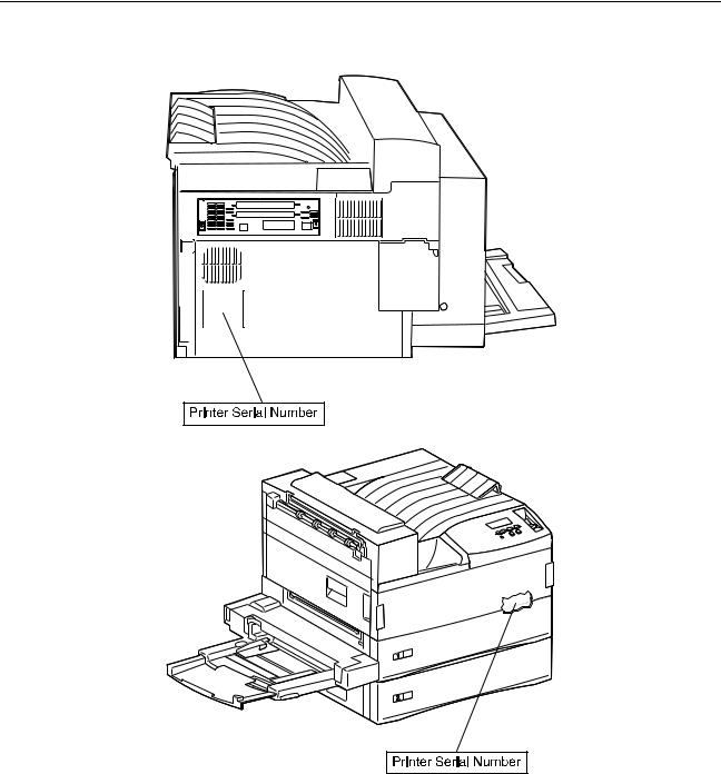
Serial Number Locations
Printer serial number labels are on the rear of the printer and inside the front cover.
1-2 Service Manual
4025-XXX
Symbols Used in this Manual
Various symbols are used throughout this manual to either provide additional information on a specific topic or to warn of possible danger that might be present during a procedure or action. Be aware of all symbols when they are used, and always read NOTE, CAUTION, and WARNING messages.
Note: A NOTE may indicate an operating or maintenance procedure, practice, or condition that is necessary to efficiently accomplish a task. A NOTE may also provide additional information related to a specific subject or add a comment on the results achieved through a previous action.
WARNING: A WARNING indicates an operating or maintenance procedure, practice, or condition that, if not strictly observed, could result in damage to, or destruction of, equipment.
CAUTION: A CAUTION indicates an operating or maintenance procedure, practice, or condition that, if not strictly observed, could result in injury.
Safety Details
Follow all safety instructions to prevent accidents while servicing this printer. Always be aware of the potential dangers that are present when you are working with electrical or mechanical equipment.
Power Supply and Electrical Components
Before starting any service procedure, switch off the printer power and unplug the power cord from the wall outlet. If you must service the printer with power applied, be aware of the potential for electrical shock.
CAUTION: Do not touch any electrical component unless you are instructed to do so by a service procedure.
General Information 1-3

4025-XXX
Mechanical Components
Manually rotate drive assemblies to inspect sprockets and gears.
CAUTION: Do not try to manually rotate or manually stop the drive assemblies while any printer motor is running.
Laser Components
CAUTION: This printer generates a laser beam as part of the printing process. The laser beam is a concentrated narrow beam of light that produces extreme heat at its focal point. The laser beam in this printer is invisible. Although you cannot see the beam, it can still cause severe damage. Direct eye exposure to the laser beam may cause eye injury or blindness.
To avoid permanent eye damage, follow these directions:
•Before starting any service procedure, switch off the printer power and unplug the power cord from the AC wall outlet.
•Do not disassemble the Printhead Assembly or any laser component that displays a Laser Warning sticker.
•Use caution when you are working around the Printhead Assembly or when you are performing laser related troubleshooting or repair procedures.
•Never place a mirror or a reflective tool or object in the laser beam path.
•Do not disassemble the printer in such a way that the laser beam can exit the print engine during a print cycle.
Fuser Components
CAUTION: This printer uses heat to fuse the toner image to a sheet paper. The Fuser Assembly is very hot. Switch off printer power and wait at least 45 minutes for the fuser to cool before you attempt to service the Fuser Assembly or adjacent components.
Safety Components
Make sure covers and panel are in place and that all interlock switches are all functioning correctly after you have completed a printer service call. If you bypass, or cheat, an interlock switch during a service call, use extreme caution when working on or around the printer.
1-4 Service Manual

4025-XXX
Caution Labels
Throughout the printer, warning labels are displayed on potentially dangerous components. When you service the printer, check to make sure that all caution labels are in place.
Most importantly, read and obey all posted caution labels.
Service Flowchart
Included is a Service Flowchart that outlines the approach to troubleshooting and repair of the printer. The Service Flowchart is an overview of the path a service technician can take, using this service manual, to service the printer.
Identify the problem. After you identify the problem, inspect and clean the printer (a thorough cleaning frequently solves many printer problems). Continue down the Flowchart in this manner, always returning to the next step in the Service Flowchart after you complete the tasks outlined in the previous step.
If you choose not to use the Service Flowchart, we recommend that you start at the appropriate Service Check and proceed from there.
Identity the Problem
1.Verify that the reported problem does exist.
2.Check for any error codes and write them down.
3.Print three test prints.
4.Make note of any print quality problems in the test prints.
5.Make note of any unusual noise or smell coming from the printer.
Inspect and Clean the Printer
1.Switch OFF printer power.
2.Disconnect the AC power cord from the wall outlet.
3.Remove the EP Cartridge and shield it from strong light.
4.Inspect the printer interior and remove any foreign matter such as paper clips, staples, pieces of paper, paper dust, or toner.
5.Clean the printer interior with a lint-free cloth, dampened slightly with cold water. Do not use solvents or chemical cleaners to clean the printer interior. Do not use any type of oil or lubricant on printer parts.
6.Clean all rubber rollers with a lint-free cloth that is dampened slightly with cold water. Use a clean, dry, lint-free cloth to dry the rollers. Do not use solvents or chemical cleaners to clean rubber rollers.
7.While you are cleaning, inspect the interior of the printer for damaged wires, loose connections, toner leakage, and damaged or obviously worn parts.
8.If the EP Cartridge appears damaged, replace it with a new one.
General Information 1-5

4025-XXX
Find the Cause of the Problem
1.Use the “Service Flowchart” on page 1-5 to find out how to use the Service Checks.
2.Use the “Service Checks” on page 2-11 to check printer components.
3.Use the “Connector Locations” on page 5-1 to locate P/Js and test points.
4.Take voltage readings at various test points.
Correct the Problem
1.Use the “Parts Catalog” on page 7-1 to locate the FRU number.
2.Use the “Removal and Replacement Procedures” on page 4-2 to replace a FRU.
Final Checkout
Test the printer to be sure you corrected the initial problem and there are no additional problems.
Printer Overview
•The printer is a 45 page per minute (35 page per minute for X830e) black and white, 600 dots per inch laser printer that uses a data-modulated laser beam, standard dryink xerographic imaging processes, and heat and pressure fusing to place a computer generated image onto the surface of a sheet of plain paper.
•The printer uses a semiconductor laser in the Printhead to generate a 5 milliwatt infrared laser beam. Image data sent from the host computer modulates the beam, creating a latent image on the surface of the electrically charged xerographic drum.
•The printer runs on 110VAC @ 60 Hz or 220VAC @ 50Hz using approximately 900 watts during an average print cycle. Two power supplies within the printer convert AC line voltage to the various AC and DC voltages that are needed for printer operation.
•Safety circuits within the printer remove power to the printer whenever the Left Front Cover is open or the EP Cartridge is removed.
•The Machine Control Unit PWB (MCU PWB) controls all printer functions, houses printer diagnostics, stores operating parameters, and signals printer errors.
•The ESS (Controller) PWB interfaces a host computer with the MCU PWB (Engine Card).
•The printer has one Customer Replaceable Unit, or CRU, that the customer must replace at specific intervals. That CRU is the EP Cartridge. The printer displays an error code when it is time to replace the EP Cartridge.
1-6 Service Manual

4025-XXX
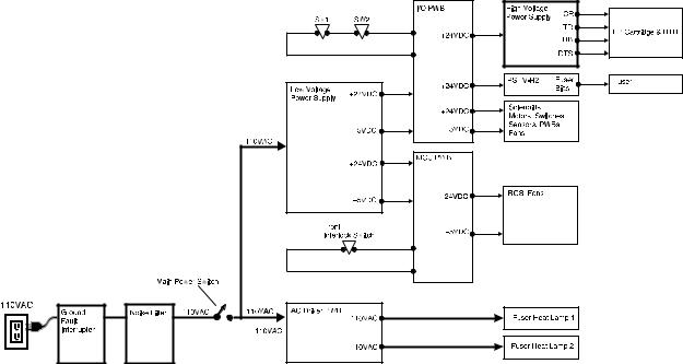
Schematic Diagram of Printer Operation
The following illustration is a simplified schematic of the printer components, subsystems, and paper paths. Refer to individual sections of the Principles of Operation for greater detail on specific areas.
General Information 1-7
4025-XXX
Power and Control
The printer power cord plugs into an AC wall outlet. The other end of the power cord plugs into the Noise Filter PWB, where the Filter removes fluctuations from the AC line voltage. A Ground Fault Interrupter in the AC line protects the printer from electrical shorts. With the Main Power Switch on, AC line voltage flows from the Noise Filter, and into the Low Voltage Power Supply (LVPS) and into the AC Driver PWB. The LVPS converts and distributes +5VDC and +24VDC voltages to the MCU PWB and I/O PWB. The MCU PWB distributes +5VDC and +24VDC to the Printhead and various printer components. The I/O PWB distributes +5VDC and +24VDC to various printer components and distributes +24VDC to the High Voltage Power Supply (HVPS) and to the PSHV-R2 power supply. The HVPS converts the +24VDC supplied to it by the MCU PWB into the high voltages that are used by the xerographic components of the printer. The PSHV-R2 provides the Fuser Bias voltage. The AC Drive PWB distributes 110VAC filtered line voltage to the two Fuser Heat Lamps.
The host computer, loaded with the correct printer driver software, connects to the printer through the ESS (Controller) PWB. The ESS PWB is connected to the MCU PWB. The ESS PWB sends image data and process information to the MCU PWB. The MCU PWB is the brain of the printer - housing printer parameters and timing tables, monitoring printer operations, and controlling all printer functions. The MCU PWB monitors sensors along the paper path, signaling the I/O PWB to switch components on and off, and generates error codes whenever sensor statuses indicate a problem.
Drive Generation and Distribution
The printer base engine contains five motors. The MCU PWB controls all motor functions. The Main Motor supplies mechanical drive to the Main Drive Assembly. The Main Drive Assembly and a series of individual gear clusters transfer drive throughout the printer.
The Drum Motor also supplies mechanical drive to the Main Drive Assembly. Electric clutches control drive to specific components. Lift Motor 1 and 2 supply drive to Trays 1 and 2. The Offset Motor supplies drive to the Offset Rollers.
Xerographics
Xerographics consists of the Printhead which houses the laser, the EP Cartridge, and the Bias Transfer Roll (BTR). Image data sent from the host computer to the MCU PWB rapidly switches the laser on and off, shining onto the Drum and creating an invisible electrical image on the surface of the electrically charged Drum. Dry ink, or toner, transfers to the Drum surface, creating a visible toner image. The Drum, the Bias Charge Roll (BCR), and the toner are all housed in the replaceable EP Cartridge. When the sheet of paper travels between the Drum and the electrically charged Bias Transfer Roll (BTR), the toner image on the Drum transfers to the sheet of paper. The Detack Saw helps remove the paper from the Drum.
1-8 Service Manual

4025-XXX
Fusing
After image transfer, the toner image is not permanently fixed to the sheet of paper - it is still dry power and can be easily rubbed off. The Fuser has two rotating rolls; the Hot Roll and the Pressure Roll. A Lamp inside each of the Rolls heats the Fuser Rolls to temperatures in access of 300°F. Paper passes between the two rolls where the toner image melts and is pressed into the surface of the paper. Fuser Drive Rolls help move the paper from the Fuser Rolls to the Exit Rolls. The Fuser Exit Sensor monitors the sheet of paper leaving the Fuser.
Paper Exit
Rolls in the Offset and Exit Unit drive the sheet of paper out of the printer and into the Face Down Output Tray or face up into the optional Duplex Module. The Full Stack Sensor monitors the level of paper in the Face Down Output Tray.
Printer Power
The power supplies in the printer provide the voltages that the printer requires to operate. The various printer functions require +5VDC, +24VDC, and several high voltage DC and AC values that are used by xerographics.
The printer AC power cord plugs into a grounded AC wall outlet. The cord carries AC line voltage to a Ground Fault Interrupter, then on to the Noise Filter PWB. The Noise Filter smooths the AC voltage and sends it to the Main Power Switch. Switching on the Main Power Switch applies AC voltage to the AC Driver PWB and to the Low Voltage Power Supply (LVPS) PWB.
The AC Driver PWB is the interface between printer control (MCU) and the Fuser. Fuser sensors connected to the AC Driver PWB send Fuser status information to the Driver PWB, which the PWB routes to the MCU PWB. The MCU processes the information and sends commands back to the AC Driver PWB to tell the AC Driver whether or not to switch on the Fuser Heat Lamps.
The Low Voltage Power Supply PWB, or LVPS, converts the 110VAC to regulated +24VDC and +5VDC voltages. The LVPS sends these voltages to the I/O PWB and to the MCU PWB. The MCU uses the voltages for internal processing and for printer component operation. The I/O PWB uses the voltages for printer component operation and also sends +24VDC to the High Voltage Power Supply PWB.
The High Voltage Power Supply PWB, or HVPS, converts the +24VDC received from the I/O PWB to the high voltages that are required by the xerographic system of the printer. The HVPS produces the Charge (CR), Transfer (TR), Developer Bias (DB), and Detack (DTS) voltages, and sends them on to the EP Cartridge Detack Saw and to the Bias Transfer Roll (BTR).
General Information 1-9
4025-XXX
The PSHV-R2 converts the +24VDC received from the I/O PWB into the bias voltage required by the Fuser.
Safety Interlocks for the printer are made up of two separate switches that are wired in series with the I/O PWB and one switch that is attached to the MCU PWB. When the Front Cover is open, the Front Cover Interlock Switch cuts +24VDC output from the MCU PWB.
When the EP Cartridge is in place, Interlock Switch SW1 is closed. When the Left Hand Cover is closed, Interlock Switch SW2 is closed. With both switches closed, the circuit is complete and the I/O PWB sends +24VDC to the HVPS and other printer components. If either SW1 is open (the EP Cartridge removed) or SW2 is open (the Left Hand Cover is open) the I/O PWB cuts all +24VDC output from the I/O PWB.
1-10 Service Manual

4025-XXX
Power Supply Components
The printer Power Supply is made up of five major components and a number of subcomponents.
1.Noise Filter PWB
Smooths and removes any fluctuation or hum from the AC line voltage.
Main Power Switch: Used to switch AC voltage on and off (switches the printer on and off).
Ground Fault Interrupter (GFI): Used as a safety measure. If there is a shortcircuit, the GFI immediately cuts AC line voltage to the Noise Filter.
2.AC Driver PWB
Receives smoothed AC voltage from the Noise Filter. The AC Driver PWB receives Fuser temperature information from Fuser sensors and passes that information on to the I/O PWB for processing. The MCU PWB signals the AC Driver to switch on or to switch off AC voltage to the Fuser Heat Lamps.
General Information 1-11
4025-XXX
3.Low Voltage Power Supply (LVPS)
Takes filtered AC voltage and converts it into regulated +24VDC and +5VDC.
The LVPS contains overcurrent protection circuits. If an excessive current begins to flow through any of the components supplied by the LVPS, the LVPS immediately shuts down all low voltage output. To reset the LVPS after an overcurrent shutdown; switch off the printer, wait a few minutes, then switch on the printer.
The LVPS contains open circuit protection circuits. If the LVPS detects that a circuit is open for longer than one minute, the LVPS slowly decreases the LVPS output until the output is zero. To reset the LVPS after an open circuit shutdown; switch off the printer, wait a few minutes, then switch on the printer.
The LVPS contains a low +24VDC output protection circuit. If the LVPS detects the +24VDC output dropping below +15VDC, the LVPS slowly decreases the +24VDC LVPS output until the output is zero.
LVPS Fan: A +24VDC fan that cools the LVPS PWB.
4.Machine Control Unit (MCU PWB)
Takes the +24VDC and +5VDC generated by the LVPS and distributes them to the various components through out the printer, including the Printhead.
Front Cover Interlock Switch: Used as a safety measure. If the Interlock Switch is closed (the Front Cover is closed) the MCU PWB sends +5VDC and +24VDC to printer components. If the Interlock Switch is open (the Front Cover is open) the MCU PWB cuts all +24VDC output.
5.I/O PWB
Takes the +24VDC and +5VDC generated by the LVPS and distributes them to the various components through out the printer, including the HVPS.
Interlock Switches SW1 and SW2: Used as a safety measure. The main interlock circuit for the printer is actually two separated switches wired in series with the I/O PWB. When the EP Cartridge is in place, Interlock Switch SW1 is closed. When the Left Front Cover is closed, Interlock Switch SW2 is closed. With both switches closed, the circuit is complete and the I/O PWB sends +24VDC to the HVPS and other printer components. If either SW1 is open (the EP Cartridge removed) or SW2 is open (the Left Front Cover is open) the I/O PWB cuts all +24VDC output.
CAUTION: Even though the interlock switches cut the +24VDC output from the MCU PWB and I/O PWB, +24VDC output from the LVPS is still present throughout the printer as well as 110VAC line voltage along the AC paths in the printer.
6.High Voltage Power Supply (HVPS)
Takes the +24VDC received from the I/O PWB and converts it into the high voltages that are required by the printer xerographic components.
The HVPS contains overcurrent protection circuits. If an excessive current begins to flow through any of the xerographic components, the HVPS immediately shuts down all high voltage output. To reset the HVPS after an overcurrent shutdown; switch off the printer, wait a few minutes, then switch on the printer.
1-12 Service Manual
Loading...