


WS 1G8
USER´S MANUAL
BEDIENUNGSANLEITUNG
MANUEL D`UTILISATION
MANUAL DE USUARIO
INSTRUKCJA OBSŁUGI
MANUALE D‘ USO
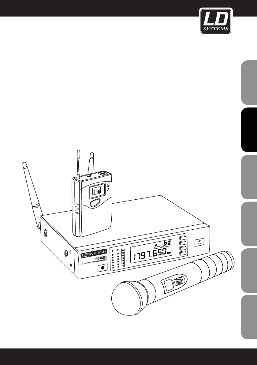
LD WS1G8
192 CHANNEL UHF TRUE DIVERSITY WIRELESS SYSTEM

ENGLISHDEUTSCHFRANCAIS
Thank you for choosing LD Systems!
We have designed this product to operate reliably over many years. Therefore LD Systems guarantees for high
quality products with its name and many years of experience as a producer.
Please take a few moments to read these instructions carefully, as we want you to enjoy your new LD Systems
products quickly and to the fullest.
For information about LD Systems check out our website WWW.LD-SYSTEMS.COM
Introduction
ESpAñoLpoLSKIITALIANo
The LD Systems WS1G8 is an advanced 192 channel true diversity UHF wireless system delivering natural
sound with a wide dynamic range, high S/N ratio and low THD in the frequency range from 1785 - 1800 MHz. It
provides consistent audio transmission from 50 Hz to 16 kHz. Handheld and bodypack feature convenient LCD
indication of channel, group and battery status. Automatic channel scanning, infrared frequency sync and the
backlit multifunction receiver display facilitate system setup and operation. The operating time ranges up to 13
hours with high quality AA size batteries.
FRANCAISFRANCAIS FRANCAISFRANCAIS
2
LD WS1G8
192 CHANNEL UHF TRUE DIVERSITY WIRELESS SYSTEM
FRANCAISFRANCAIS FRANCAISFRANCAIS
FRANCAISDEUTSCHENGLISH
ITALIANOPOLSKIESPAÑOL
3

PREVENTIVE MEASURES:
1. Please read this information carefully.
2. Keep all information and instructions in a safe place.
3. Please follow the instructions.
ENGLISHDEUTSCHFRANCAIS
4. Please observe all warnings. Don‘t remove safety instructions or any other information located on the device.
5. Use the device only in the intended manner.
6. Use only stable and appropriate stands and/or mounts when the device is permanently installed. Make certain
that wall brackets are firmly secured. Make certain that the unit is installed securely and cannot fall down.
7. When installing please observe the corresponding safety standards for your country.
8. Do not install the device near radiators, heat accumulators, ovens or other sources of heat. Make certain that
the device is always installed so that is cooled sufficiently and cannot overheat.
9. Do not place open sources of ignition, e.g., burning candles, on the device.
10. Do not cover ventilation slots.
11. Do not operate the device in the immediate vicinity of water. Do not expose this equipment to combustible
materials, liquids or gases.
12. Please make certain that dripping or splashing water cannot get inside the device. Do not put objects filled
with fluids, such as vases or drinking vessels, on top of the device.
13. Make certain that objects cannot fall into the device.
14. Use the device only with accessories with which the manufacturer intends the device to be used.
15. CAUTION: If this device has a mains connector equipped with protective earth, it must be connected to a
mains socket with a protective ground connection. Never disable the function of the protective ground connection
of the included power cord.
16. Do not turn on the device immediately if it was exposed to strong temperature fluctuations (for example after
transportation). Moisture and condensation may damage the device. Leave the device switched off until it has
reached room temperature.
17. Do not open the device and do not make any changes to the device.
18. Before connecting to mains power, make certain that the mains voltage and the mains frequency are the
ESpAñoLpoLSKIITALIANo
same as the operating values of the device (see type label). If the device is equipped with a supply voltage selector switch, make certain that the values of the device match the values of the mains power before connecting.
If the plug on the included cord does not fit your mains outlet, contact your electrician.
19. Make certain that the power cord is not stepped on. Protect the power cord against pinching, especially at
the device plug and the power plug.
20. In order to prevent damage or accidents, for example, due to tripping hazards, check all connections once
you have connected the device.
FRANCAISFRANCAIS FRANCAISFRANCAIS
21. When connecting the device, make certain that the power plug remains readily accessible.
Always pull out the power plug when the device is not in use or when you clean the device. Disconnect the
power cord by pulling the plug not the cable. Never touch the power cable and power adapter with wet hands.
22. Avoid switching the device on and off at short intervals, because it may shorten the durability of the device.
23. IMPORTANT: Replace fuse only by fuse of same type and rating! If fuse blows repeatedly please contact
authorized service center!
24. In order to disconnect the device completely from the mains voltage, the power plug must be unplugged.
25. If your device is equipped with a Volex power connector, the matching Volex device plug must be unlocked
in order to disconnect it. This also means that a tug on the power cord can pull the device out of place, thus
causing personal injuries and/or property damage. Thus please make certain to route your cables carefully.
4
PREVENTIVE MEASURES:
26. If there is a risk of lightning strike or during extended periods of disuse, unplug the power plug.
27. During transport, make certain that the equipment being transported cannot fall down and possibly
cause personal injuries and/or property damage.
28. If your device no longer works properly, if it has been exposed to liquids or an object has fallen inside it or
if it has been damaged in some other manner, turn the device off immediately und unplug the power plug. This
device should be repaired only by authorized experts.
29. Use only a dry cloth to clean the device.
30. Comply with all of the disposal laws that are applicable in your country. During disposal, please separate
plastic and paper/cardboard.
31. Plastic bags must be kept out of the reach of children.
ENGLISH
FRANCAISFRANCAIS FRANCAISFRANCAIS
CAUTION
RISK OF ELECTRIC SHOCK
DO NOT OPEN
CAUTION:
To reduce the risk of electric shock, do not remove cover (or back). No user serviceable parts inside. Refer
servicing to qualified personnel.
The lightning flash with arrowhead symbol within an equilateral triangle is intended to alert the
user to the presence of uninsulated “dangerous voltage” within the product´s enclosure that may be
of sufficient magnitude to constitute a risk to persons.
The exclamation mark within an equilateral triangle is intended to alert the user to the presence of
important operating and maintenance (servicing) instructions in the literature accompanying the
appliance.
CAUTION! HIGH VOLUME!
This product is designed for professional use. Therefore the commercial use of this equipment is liable to the
rules and regulations of the Accident Prevention & Insurance Association of your industry sector. Adam Hall as a
manufacturer is bound to inform you formally about the existence of eventual sanitary risks.
Risk of hearing damage due to prolonged exposure to excessive volumes: When using this product high sound
pressure levels (SPL) can be generated, sufficient to cause permanent hearing damage to performers, production
crew and audience members. Caution should be taken to avoid prolonged exposure SPL in excess of 90 dB.
FRANCAISDEUTSCHENGLISH
ITALIANOPOLSKIESPAÑOL
5

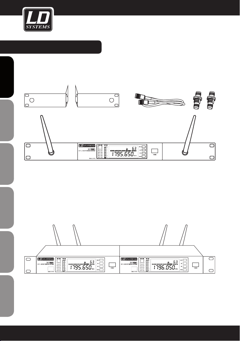
SYSTEM COMPONENTS & INSTALLATION:
ALL SINGLE RECEIVER SYSTEMS INCLUDE
1 x WS1G8 single receiver
1 x WS1G8 transmitter (handheld or bodypack with microphone / guitar cable)
2 x antenna
ENGLISHDEUTSCHFRANCAIS
1 x power adapter
2 x AA size battery
1 x audio cable
1 x user‘s manual
1 x carrying case
ALL DOUBLE RECEIVER SYSTEMS INCLUDE
1 x WS1G8 double receiver
2 x WS1G8 transmitter (handheld or bodypack with microphone / guitar cable)
2 x antenna
1 x power adapter
4 x AA size battery
1 x audio cable
1 x rack kit (2 x rack mount brackets, 2 x TNC cable, 2 x TNC adapter, 2 x dummy plates, 1 set of screws)
1 x user‘s manual
1 x carrying case
INSTALLATION
For best possible reception place the receiver at a minimum height of 1 m and align the antennas upwards in
V-shape. Attend that transmitters and receivers are in direct line-of-sight and make sure that there is a minimum
distance of 50 cm between receiving antennas and metal objects. Do not position receivers near digitally controlled devices.
ESpAñoLpoLSKIITALIANo
FRANCAISFRANCAIS FRANCAISFRANCAIS
6
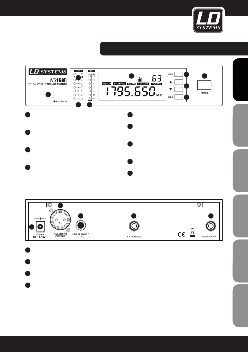
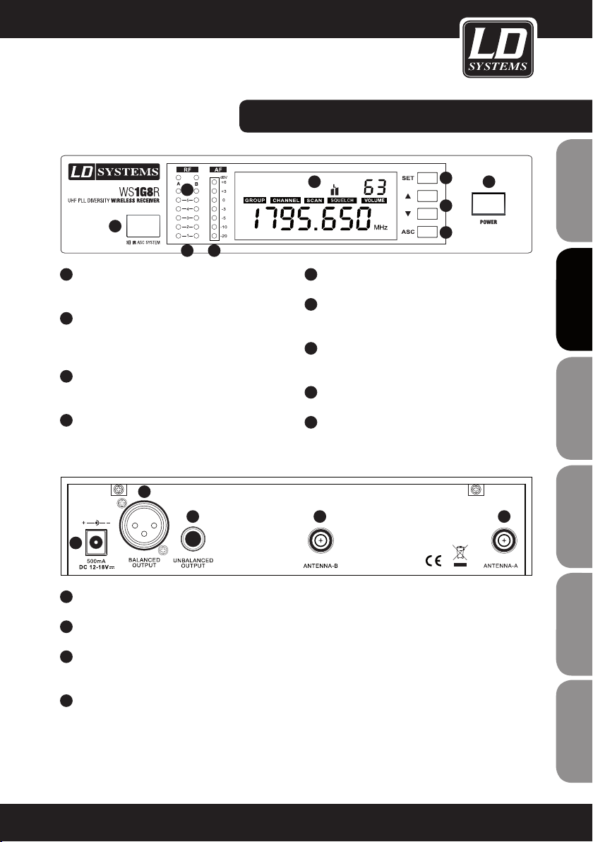
WS1G8R fRONT- / BACk PANEL:
6
5
87
1
POwER ON / Off
Push and hold for 1 second
2
SET BUTTON
Push and hold for 1 second to access menu items
3
VOLUME / VALUE
Up and Down buttons
4
ASC BUTTON
Frequency sync via infrared
2
3 1 1
4
9
5
INfRARED INTERfACE
6
ANTENNA A / B LEDS
Indicates whether antenna input A or B is active
7
6 SEGMENT Rf (RADIO fREqUENCY) SIGNAL
LEVEL METER ANTENNA INPUT A / B.
8
7 SEGMENT AUDIO LEVEL METER
9
ILLUMINATED MULTIfUNCTIONAL DISPLAY
2
3
4
1
FRANCAISFRANCAIS FRANCAISFRANCAIS
FRANCAISDEUTSCHENGLISH
1
TNC SOCkETS ANTENNA A / B.
2
BALANCED XLR OUTPUT.
3
UNBALANCED 6.3 MM jACk OUTPUT.
4
DC SOCkET. ONLY USE THE SUPPLIED POwER
ADAPTER.
ITALIANOPOLSKIESPAÑOL
7
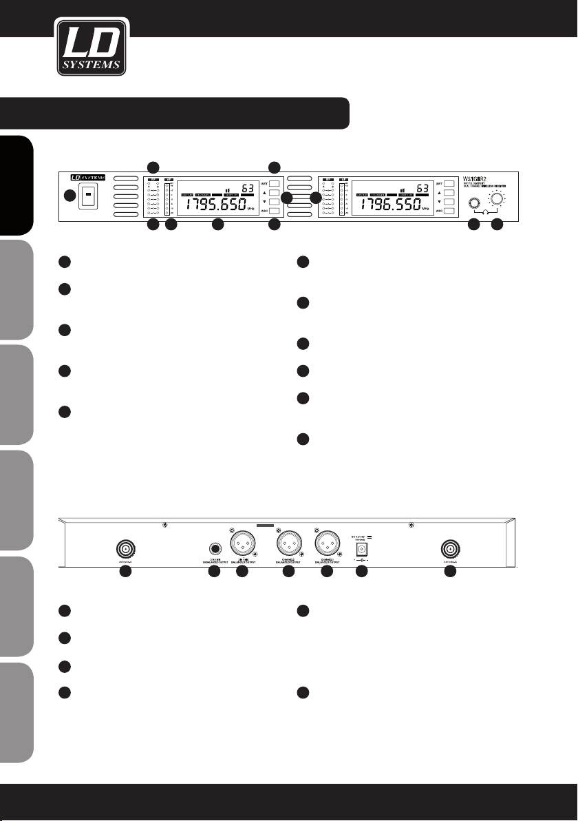
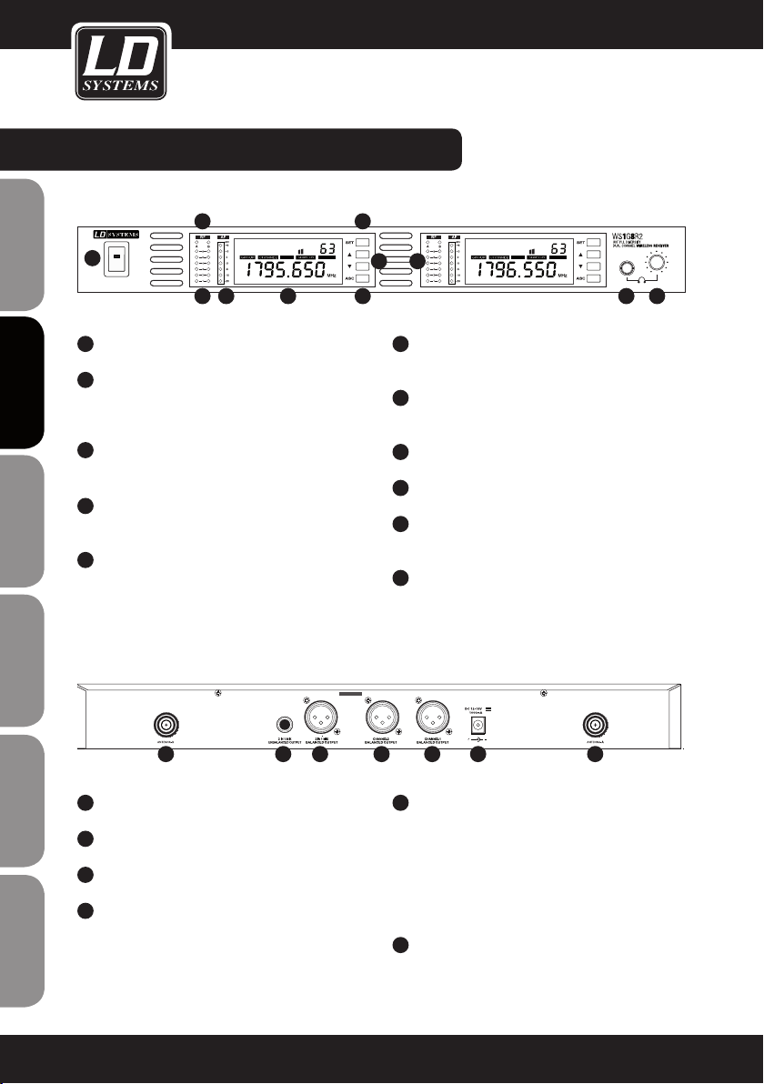
WS1G8R2 fRONT- / BACk PANEL:
VOLUMEAUTO
L
VOLUME
L
AUTO
ENGLISHDEUTSCHFRANCAIS
1
1
2
3
4
5
ESpAñoLpoLSKIITALIANo
6
L
VOLUMEAUTO
7 8 9
POwER ON / Off.
SET BUTTON
Push and hold for 1 second to access menu items
VOLUME / VALUE
Up and Down buttons
ASC BUTTON
Frequency sync via infrared
INfRARED INTERfACE
2
L
VOLUME
3 5
4
6
ANTENNA A / B LEDS
AUTO
Indicates whether antenna input A or B is active
7
6 SEGMENT Rf (RADIO fREqUENCY) SIGNAL
LEVEL METER ANTENNA INPUT A / B
8
7 SEGMENT AUDIO LEVEL METER
9
ILLUMINATED MULTIfUNCTIONAL DISPLAY
10
HEADPHONES OUTPUT
6.3 mm stereo jack.
11
HEADPHONES VOLUME.
10 11
1
FRANCAISFRANCAIS FRANCAISFRANCAIS
2
3
4
8
1 5 4 3 2 6 1
TNC SOCkETS ANTENNA A / B
BALANCED XLR OUTPUT CHANNEL 1
BALANCED XLR OUTPUT CHANNEL 2
BALANCED XLR MIX OUTPUT
This output provides a mix of both receivers
audio signals. For individual volume control adjust
the volume on the front panel of each receiver
separately.
5
UNBALANCED MIX 6.3 MM jACk OUTPUT
This output provides a mix of both receivers
audio signals. For individual volume control adjust
the volume on the front panel of each receiver
separately.
6
DC SOCkET. ONLY USE THE SUPPLIED POwER
ADAPTER
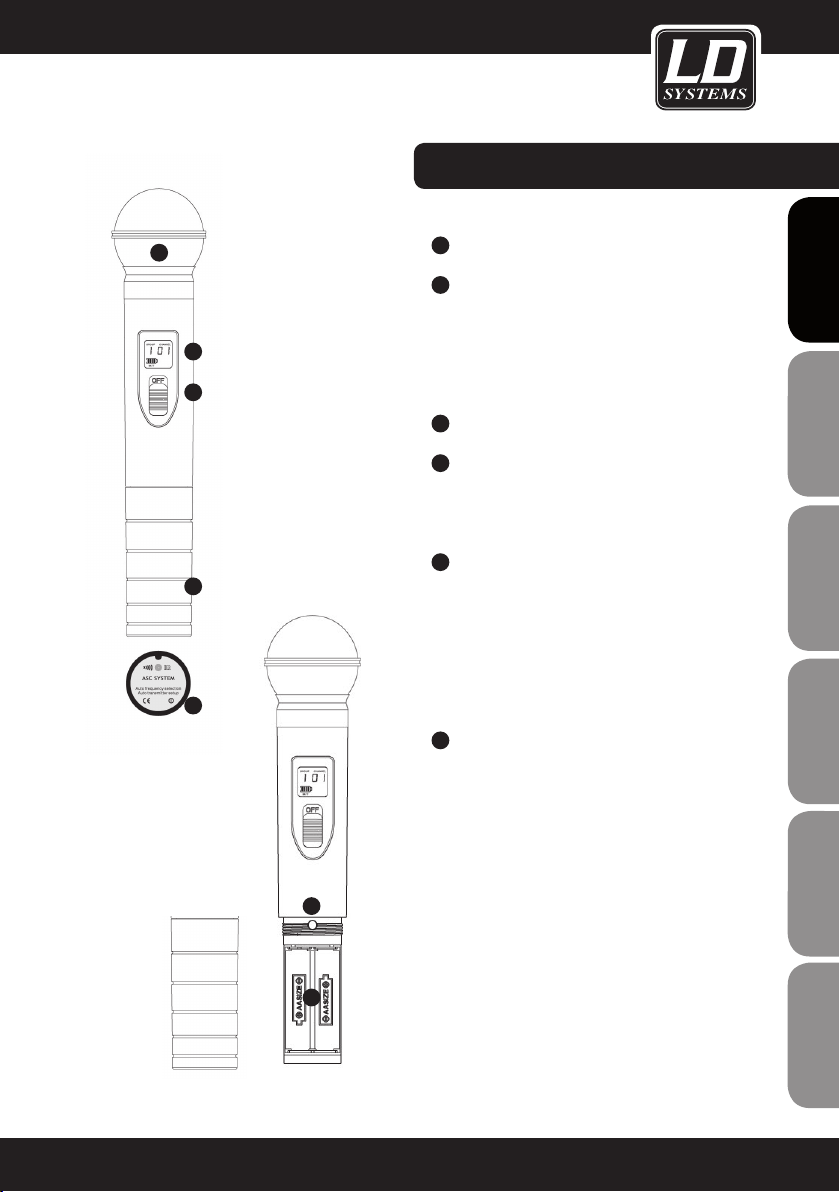
HANDHELD MICROPHONE:
1
1
2
3
5
6
4
MICROPHONE HEAD
2
BACkLIT LCD
Displays group, channel and a 4 segment battery
status indicator. If the battery symbol blinks, the
batteries need to be replaced immediately.
NOTE: Backlight will turn off automatically after a
brief moment.
3
ON / Off SwITCH
4
GAIN CONTROL
Handle carefully! Use only suitable screwdriver!
Turn left to decrease gain, turn right to increase
gain.
5
BATTERY COMPARTMENT
To replace batteries, unscrew cover counterclockwise, remove batteries, insert 2 new AA size
batterries (direction as shown in the compartment) and screw the cover onto the handheld
microphone clockwise. Make shure that the
cover is screwed tightly in order to maintain safe
operation.
6
IR INfRARED INTERfACE
Located on the bottom side of the handheld
microphone.
For frequency synchronisation push the ASC button on the receiver (the ASC symbol in the display
blinks) and hold the (switched on) transmitter with
its infrared interface facing direct to the infrared
interface of the receiver in a distance between 5
and 20 cm.
FRANCAISFRANCAIS FRANCAISFRANCAIS
FRANCAISDEUTSCHENGLISH
5
ITALIANOPOLSKIESPAÑOL
9

BODYPACk TRANSMITTER:
1
ON / Off AND MUTE SwITCH
Push and hold for 2 seconds to switch transmitter
ENGLISHDEUTSCHFRANCAIS
ESpAñoLpoLSKIITALIANo
on or off.
Press briefly to activate mute function. Press
again briefly to deactivate mute function.
2
BACkLIT LCD
Displays group, channel and a 3 segment battery
status indicator. If the battery symbol and the
green ASC LED blink, the batteries need to be
replaced immediately. Note: Backlight will turn off
automatically after a brief moment.
3
ANTENNA
4
ASC LED
Green LED lights up continuously if power is
switched on.
Green LED blinks during frequency synchronisation.
Green LED blinks when batteries are low.
5
MUTE LED
Lights up red when mute function is activated.
6
BATTERY COMPARTMENT
To replace batteries slightly press on marked positions on left and right side of the cover and open
forward. Remove batteries, insert 2 new AA size
batteries (direction as shown in the compartment)
and close the cover.
3
2
1
7
4
5
8
6
FRANCAISFRANCAIS FRANCAISFRANCAIS
10
7
IR INfRARED INTERfACE
For frequency synchronisation open cover and
push the ASC button on the receiver (the ASC
symbol in the display blinks) and hold the (switched on) transmitter with its infrared interface facing direct to the infrared interface of the receiver
in a distance between 5 and 20 cm.
8
SELECT
Manual setting of group and channel.
Open cover, press and hold button until only group
number appears. Release button. Group number
blinks. Now press button briefly to change value
step by step until desired group appears. Carry out
the same procedure to change channel number.
The display will return to standard after a short
period of time of non-activity automatically.

9
INPUT
3-pin mini XLR input for the supplied microphone
or guitar cable.
BODYPACk TRANSMITTER:
10
GAIN SwITCH
Select the appropriate gain setting.
MIC = microphone
0dB = guitar with passive pickup
-10dB = guitar with active pickup
If the audio signal overloads the receiver, switch
the gain to the next lower setting.
11
BELT CLIP
Attach the bodypack to a belt or guitar strap as
shown below.
BODYPACk MINI-XLR PIN ASSIGNMENT
MINI-XLR
2
3
1
6,3 mm jack
sleeve tip
9
10
FRANCAISFRANCAIS FRANCAISFRANCAIS
FRANCAISDEUTSCHENGLISH
11
MINI-XLR
2
1
3
Headset, lavalier or wind instrument microphoneGuitar & Bass and other high impendance sources
MINI-XLR
R
2,2k
2
1
3
Headset, lavalier or wind instrument microphone with low sensitivity. 2,2 kOhm
resistor soldered on pin 2 and pin 3 increases gain.
ITALIANOPOLSKIESPAÑOL
11
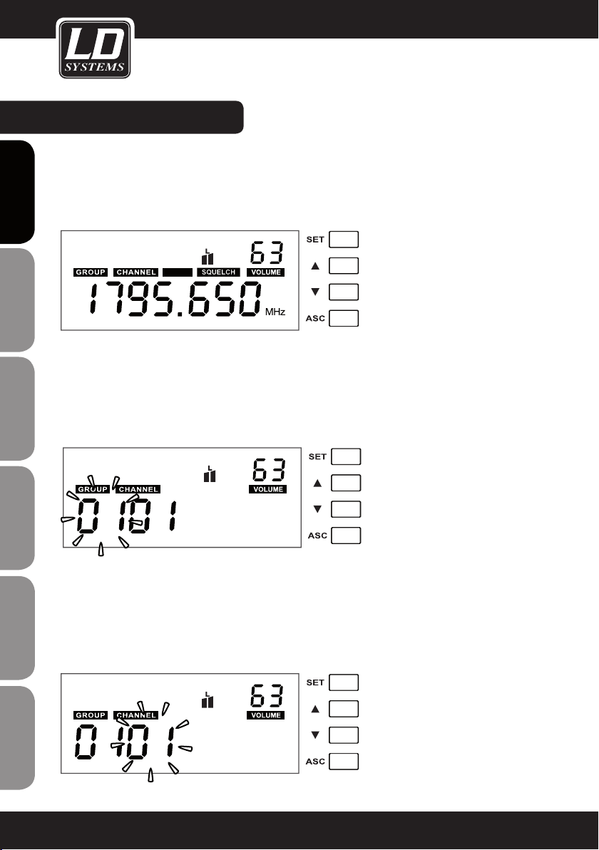
SYSTEM SETTINGS:
STANDARD DISPLAY
The standard display shows the preselected frequency, squelch setting and volume.
VOLUME
Use the Up and Down buttons to set the desired volume (00 - 63).
ENGLISHDEUTSCHFRANCAIS
AUTO
GROUP
Push the SET button and hold it for 1 second. GROUP and first two digits blink. Push the Up and Down buttons to
set the desired group (01 - 16). Press SET again to confirm.
The display will return to standard after a short period of time of non-activity automatically.
NOTE: Each of the groups 01 - 16 consists of 12 channels, each corresponding to a specific frequency.
ESpAñoLpoLSKIITALIANo
CHANNEL
Push the SET button, hold it for 1 second and press SET again. CHANNEL and 2 digits below blink. Push the Up
and Down buttons to set the desired channel (01 - 12). Press SET again to confirm.
The display will return to standard after a short period of time of non-activity automatically.
Once a specific frequency (group and channel) has been selected, the transmitter (handheld or bodypack) has to
FRANCAISFRANCAIS FRANCAISFRANCAIS
be synchronized to the same frequency (group and channel) via the ASC function.
12
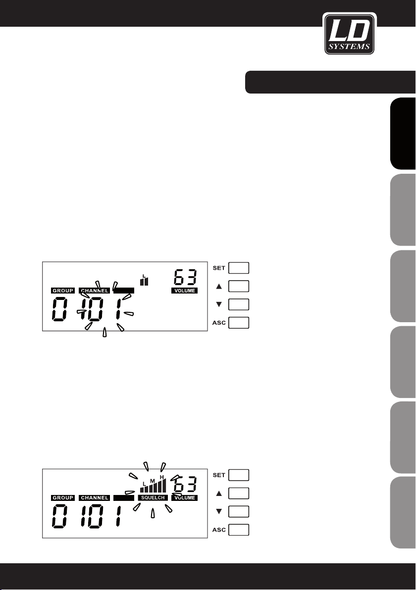
SYSTEM SETTINGS:
CHANNEL SCAN fUNCTION
Push the SET button, hold it for 1 second and press SET again twice. CHANNEL, AUTO and 2 digits below blink.
Push the Up or Down button to start the channel scan process. After scanning is complete, the display shows the
automatically selected interference free channel.
When using multi-systems and frequency selection is done by the channel scan function, already set up systems
should remain switched on for further channel scan processes. The frequency scan function relates to the
frequency presets in the pre-selected group (01 - 16).
The accuracy of the scan result depends on the environment and the number of simultaneously used wireless
systems. If the scan function does not recognize an already used frequency under adverse conditions, start the
scan process again until an open frequency has been located.
Note: Each frequency channel must come from the same group (01 - 16) when using multi-systems.
Important: Do not operate more than one wireless system on the same frequency at the same time and location.
This causes unwanted loud noise due to radio interference.
AUTO
SqUELCH
The squelch function eliminates unpleasant noise when the transmitter is switched off. It also suppresses sudden noise when there is no longer sufficient transmission power received by the receiver.
Adjust the squelch (with transmitter switched off) to the lowest possible setting that suppresses unwanted noise.
Recommended setting for standard applications is „L“. Setting “H” can cause smaller distance of transmission
path under unfavourable conditions.
Push the SET button, hold it for 1 second and press SET again 3 times. SQUELCH and the symbols above blink.
Push the Up and Down buttons to adjust the desired setting (L = Low, M = Mid, H = High). Press SET again to
confirm.
The display will return to standard after a short period of time of non-activity automatically.
CAUTION: Set the volume of the connected PA system to a minimum before adjusting the squelch function!
FRANCAISFRANCAIS FRANCAISFRANCAIS
FRANCAISDEUTSCHENGLISH
AUTO
ITALIANOPOLSKIESPAÑOL
13

SYSTEM SETTINGS:
ASC (frequency synchronisation via infrared)
The transmission frequency of a wireless system has to be the same in both transmitter and receiver.
Once a specific frequency (group and channel) has been selected, the transmitter (handheld or bodypack) has to
be synchronized to the same frequency (group and channel) via the ASC function.
ENGLISHDEUTSCHFRANCAIS
Push the ASC button
mitter with its infrared interface
5 and 20 cm. After a short moment the synchronisation process is done and the RF signal level meter
receiver indicates a signal.
2
ESpAñoLpoLSKIITALIANo
1
on the receiver (the ASC symbol in the display blinks) and hold the (switched on) trans-
2
facing direct to the infrared interface of the receiver in a distance between
1
2
3
of the
LOw BATT (low batteries)
FRANCAISFRANCAIS FRANCAISFRANCAIS
If the „LOW BATT“ indicator blinks in the receiver display, the batteries in the transmitter must be replaced immediately..
14
3

PROBLEM DISPLAY SOLUTION
No sound or volume
too low.
Transmitter: Display is turned
off.
Receiver: Display is turned off. Check power connection.
Receiver: RF indicator is off.
Transmitter: Power is turned
on.
Make certain that transmitter is turned on.
Make sure that batteries are ok.
Turn power on.
Check up that transmitter and receiver are set to
the same frequency.
Reduce distance between transmitter and receiver.
Attend that transmitter and receiver are in direct
line-of-sight.
TROUBLE SHOOTING:
FRANCAISFRANCAIS FRANCAISFRANCAIS
Distortion or unwanted
noise.
Distorted sound.
Receiver: RF indicator is
illuminated.
Bodypack transmitter: Display
is turned on, Mute LED lights
up.
Receiver: RF indicator is
illuminated.
Receiver: RF indicator is
illuminated.
Transmitter: Battery symbol
blinks.
Receiver: AF level meter too
high.
Make certain that antennas of receiver are con
nected and positioned upwards in V-shape.
Deactivate mute function.
Increase volume of receiver.
Increase gain of transmitter.
Check audio connection of receiver and mixing
board.
Check mixing board settings.
Remove possible reasons of interference (digitally
controlled units, other wireless systems in same
location).
Set wireless system to different transmission
frequency.
Replace batteries
Reduce gain of transmitter.
-
FRANCAISDEUTSCHENGLISH
ITALIANOPOLSKIESPAÑOL
15
RACk INSTALLATION:
RACkMOUNT kIT LDwS100Rk (OPTIONAL) fOR 1 X LDwS1G8 RECEIVER CONSISTING Of:
2 X RACk BRACkETS, 2 X TNC CABLES, 2 X TNC ADAPTERS, SET Of SCREwS
ENGLISHDEUTSCHFRANCAIS
RACkMOUNT kIT LDwS100Rk2 (OPTIONAL) fOR 2 X LDwS1G8 RECEIVER CONSISTING Of:
1 X 19“ RACk ADAPTER, SET Of SCREwS
ESpAñoLpoLSKIITALIANo
FRANCAISFRANCAIS FRANCAISFRANCAIS
16
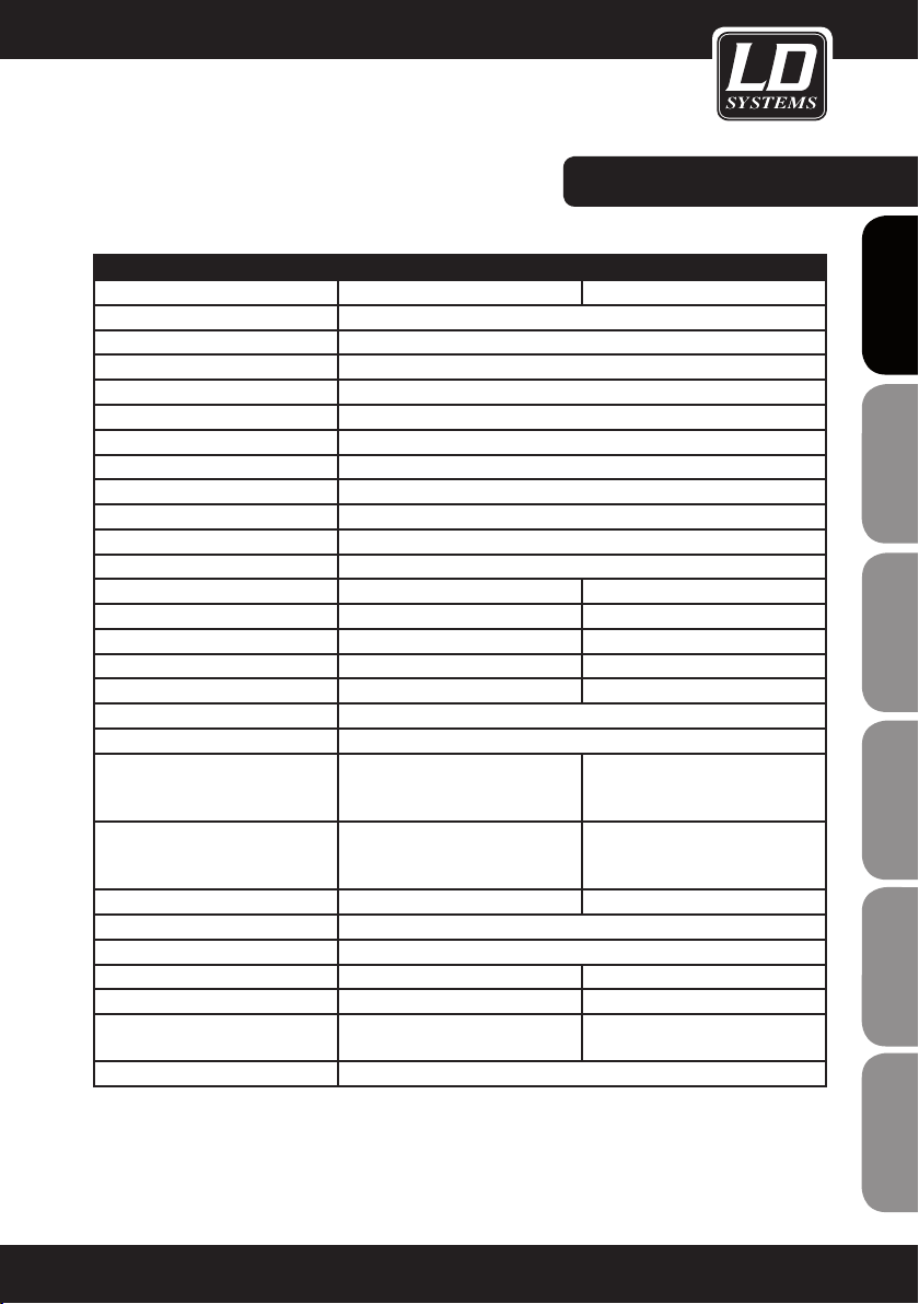
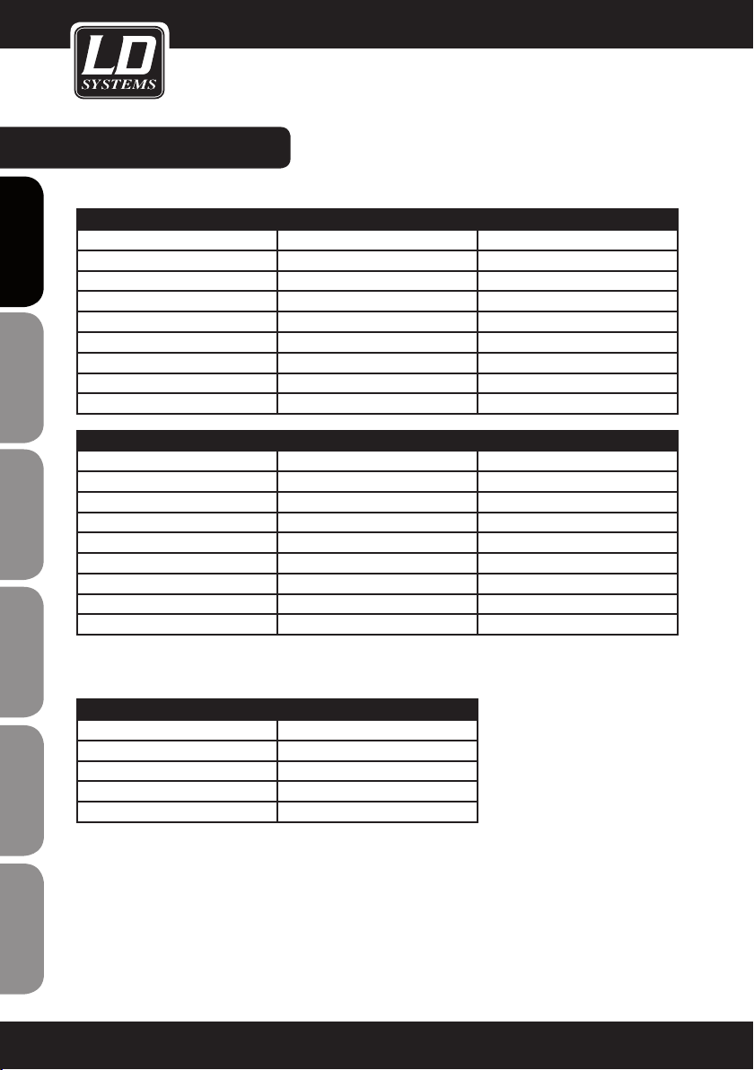
SPECIfICATIONS:
RECEIVER
Model name: LDWS1G8R LDWS1G8R2
Receiver type: true diversity
Modulation: FM
Frequency range: 1785 - 1800 MHz
Channels: 192 (16 x 12)
Groups: 16
Antenna connectors: 2 x TNC
Frequency response: 50 - 16.000 Hz
Squelch: Low, Mid, High
Transmission optimisation: Pilot tone
THD: <0.8%
Signal-to-noise ratio: >90 dB
Balanced output: XLR 2 x XLR
Balanced mix output: XLR
Unbalanced output: 6.3 mm jack
Unbalanced mix output: 6.3 mm jack
Headphones output: 6.3 mm stereo jack
Audio output level (balanced): +6 dBu
Audio output level (unbalanced): 0 dBu
Controls:
Indicators:
Operating voltage: 12 - 18 V DC, 500 mA 12 - 18 V DC, 1000 mA
Operating temperature range: -10°C … 45°C
Relative humidity in operation: 25% … 85%
Dimensions (W x H x D): 212 x 45 x 163 mm 483 x 45 x 163
Weight: 0,92 kg 2,24 kg
Accessories included:
Features: channel scan function, infrared frequency synchronisation
power on/off, set, value up, value
down, ASC
multifunctional LC-display, HF-level
antenna A/B, audio level
power adapter, 2 x antenna, audio
cable
power on/off, 2 x set, 2 x value up,
2 x value down, 2 x ASC, headphones volume
2 x multifunctional LC-display, 2
x HF-level antenna A/B, 2 x audio
level
power adapter, 2 x antenna, audio
cable, rack kit
FRANCAISFRANCAIS FRANCAISFRANCAIS
FRANCAISDEUTSCHENGLISH
ITALIANOPOLSKIESPAÑOL
17
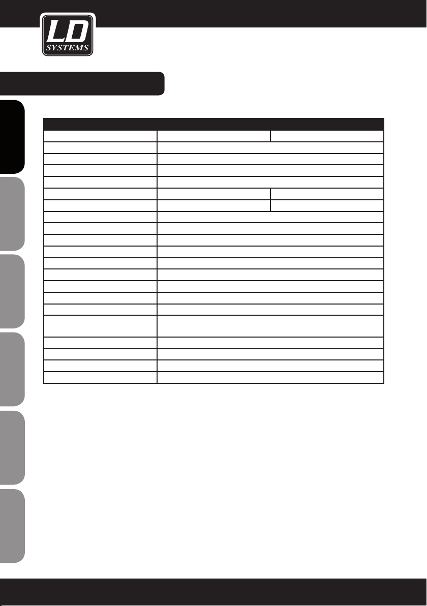
SPECIfICATIONS:
HANDHELD TRANSMITTER
Model name: LDWS1G8MD LDWS1G8MC
ENGLISHDEUTSCHFRANCAIS
ESpAñoLpoLSKIITALIANo
Modulation: FM
Frequency range: 1785 - 1800 MHz
Channels: 192 (16 x 12)
Groups: 16
Microphone type: dynamic condenser
Polar pattern: cardioid cardioid
Frequency response: 50 - 16.000 Hz
THD: <0.8%
Signal-to-noise ratio: >90 dB
RF output power: 10 mW
Controls: Power on/off
Indicators: multifunctional LC-display
Power supply: 2 x AA battery
Operating time: up to 13 h (depending on batteries)
Operating temperature range: -10°C … 45°C
Relative humidity range in ope-
ration:
Dimensions (L x Ø): 245 x 51 mm
Weight: 0,34 kg
Accessories included: 2 x AA battery
Features: infrared frequency synchronisation
25% … 85%
FRANCAISFRANCAIS FRANCAISFRANCAIS
18
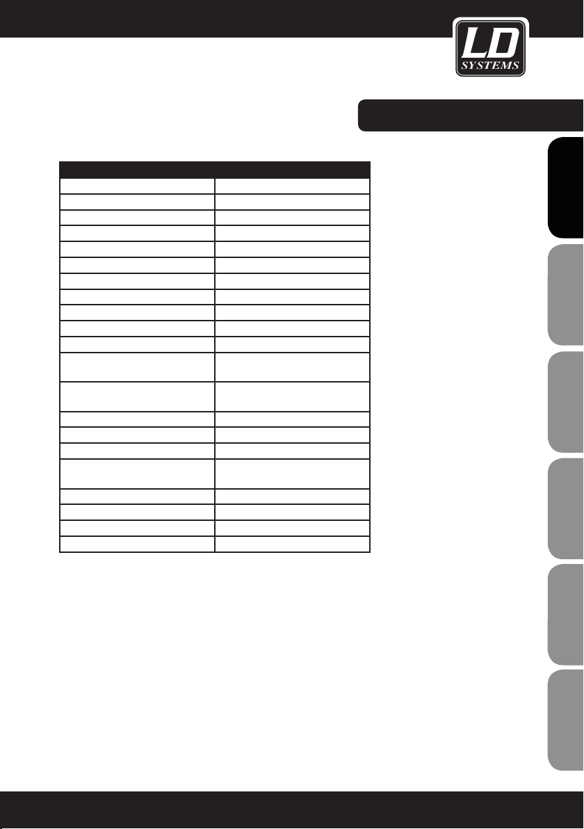
BODYPACk TRANSMITTER
Model name: LDWS1G8BP
Modulation: FM
Frequency range: 1785 - 1800 MHz
Channels: 192
Groups: 16
Input: 3-pin mini-XLR
Frequency response: 50 - 16.000 Hz
THD: <0.8%
Signal-to-noise ratio: >90 dB
RF output power: 10 mW
Controls:
Indicators:
Power supply: 2 x AA batteries
Operating time: up to 13 h (depending on batteries)
Operating temperature range: -10°C … 45°C
Relative humidity range in ope-
ration:
Dimensions (W x H x D): 65 x 90 x 24 mm
Weight (without batteries): 0,09 kg
Accessories included: 2 x AA battery
Features: infrared frequency synchronisation
Power / Mute, select, triple gain
switch
multifunctional LC-display, ASC
LED, Mute LED
25% … 85%
SPECIfICATIONS:
FRANCAISFRANCAIS FRANCAISFRANCAIS
FRANCAISDEUTSCHENGLISH
ITALIANOPOLSKIESPAÑOL
19
SPECIfICATIONS:
MICROPHONE
ENGLISHDEUTSCHFRANCAIS
Model name: LDWS100MH1 LDWS100MH3
Microphone type: headset headset
Capsule: back-electret condenser back-electret condenser
Polar pattern: cardioid cardioid
Frequency response: 20 - 20.000 Hz 70 - 16.000 Hz
Connector: 3-pin mini-XLR 3-pin mini-XLR
Accessories included: foam windscreen foam windscreen
Features:
LDHSAE1 LDWS100ML LDWS1000MW
headset lavalier microphone wind instrument microphone
back-electret condenser back-electret condenser back-electret condenser
bi-directional cardioid cardioid
80 - 16.000 Hz 20 - 20.000 Hz 50 - 18.000 Hz
3-pin mini-XLR 3-pin mini-XLR 3-pin mini-XLR
foam windscreen foam windscreen foam windscreen
water-repellent
ESpAñoLpoLSKIITALIANo
GUITAR CABLE
Model name: LDWS100GC
Connector 1: 3-pin mini-XLR
FRANCAISFRANCAIS FRANCAISFRANCAIS
Connector 2: 6.3 mm jack
Lenght: 1.5 m
20

MANUfACTURER´S DECLARATIONS:
LIMITED wARRANTY
This Limited Warranty applies to the Adam Hall, LD Systems, Defender, Palmer, Cameo and Eminence branded
products.
The statutory warranty rights towards the seller are not affected by this guarantee. In fact, it justifies, additional
independent warranty claims towards Adam Hall.
Adam Hall warrants that the Adam Hall product you have purchased from Adam Hall or from an Adam Hall authorized reseller is free from defects in materials or workmanship under normal use for a period of 2 or 3 years from
the date of purchase.
The Limited Warranty Period starts on the date of purchase. In order to receive warranty services you are required
to provide proof of the purchase date. Your dated sales or delivery receipt, showing the date of purchase, is your
proof of the purchase date. Should products of the brands named above be in need of repair within the limited warranty period, you are entitled to warranty services according to the terms and conditions stated in this document.
This Limited Warranty extends only to the original purchaser of this Adam Hall branded product and is not transferable to anyone who obtains ownership of the Adam Hall branded product from the original purchaser. During
the Limited Warranty Period, Adam Hall will repair or replace the defective component parts or the product. All
component parts or hardware products removed under this Limited Warranty become the property of Adam Hall.
In the unlikely event that your Adam Hall product has a recurring failure, Adam Hall, at its discretion, may elect to
provide you with a replacement unit of Adam Hall´s choice that is at least equivalent to your Adam Hall branded
product in hardware performance.
Adam Hall does not warrant that the operation of this product will be uninterrupted or error-free. Adam Hall is not
responsible for damage that occurs as a result of your failure to follow the instructions included with the Adam
Hall branded product.
This Limited Warranty does not apply,
- to wear parts (e.g. accumulator)
- to any product from which the serial number has been removed or that has been damaged or rendered defective as the result of an accident
- in case of, misuse, abuse, or other external causes
- by operation outside the usage parameters stated in the user´s documentation shipped with the product by use
of spare parts not manufactured or sold by Adam Hall
- by modification or service by anyone other than Adam Hall
These terms and conditions constitute the complete and exclusive warranty agreement between you and Adam
Hall regarding the Adam Hall branded product you have purchased.
FRANCAISFRANCAIS FRANCAISFRANCAIS
FRANCAISDEUTSCHENGLISH
ITALIANOPOLSKIESPAÑOL
21

MANUfACTURER´S DECLARATIONS:
LIMITATION OF LIABILITY
If your Adam Hall branded hardware product fails to work as warranted above, your sole and exclusive remedy
shall be repair or replacement. Adam Halls’ maximum liability under this limited warranty is expressly limited
ENGLISHDEUTSCHFRANCAIS
to the lesser of the price you have paid for the product or the cost of repair or replacement of any hardware
components that malfunction in conditions of normal use.
Adam Hall is not liable for any damages caused by the product or the failure of the product, including any lost
profits or savings or special, incidental, or consequential damages. Adam Hall is not liable for any claim made by
a third party or made by you for a third party.
This limitation of liability applies whether damages are sought, or claims are made, under this Limited Warranty
or as a tort claim (including negligence and strict product liability), a contract claim, or any other claim. This limitation of liability cannot be waived or amended by any person. This limitation of liability will be effective even if
you have advised Adam Hall of an authorized representative of Adam Hall of the possibility of any such damages.
This limitation of liability however, will not apply to claims for personal injury.
This Limited Warranty gives you specific legal rights. You may also have other rights that may vary from state to
state or from country to country. You are advised to consult applicable state or country laws for a full determination of your rights.
REQUESTING wARRANTY-SERVICE
To request warranty service for the product, contact Adam Hall or the Adam Hall authorized reseller from which
you purchased the product.
EC DECLARATION OF CONFORMITY
ESpAñoLpoLSKIITALIANo
These devices meet the essential requirements and further relevant specifications of Directives 1999/5/EC (R &
TTE), 2004/108/EC (EMC) and 2006/95/EC (LVD). For more information, see www.adamhall.com.
CORRECT DISPOSAL OF THIS PRODUCT (ELECTRICAL WASTE)
(Applicable in the European Union and other European countries with separate collection systems)
This marking shown on the product or its literature, indicates that it should not be disposed with other household
wastes at the end of its working life. To prevent possible harm to the environment or human health from uncon-
FRANCAISFRANCAIS FRANCAISFRANCAIS
trolled waste disposal, please separate this from other types of wastes and recycle it responsibly to promote the
sustainable reuse of material resources.
Household users should contact either the retailer where they purchased this product, or their local government
office, for details on where and how they can recycle this item in an enviromentally friendly manner.
Business users should contact their supplier and check the terms and conditions of the purchase contract. This
product should not be mixed with other commercial wastes for disposal.
22
wEEE-DECLARATION
Your LD-Systems product was developed and manufactured with high quality materials and components wich
can be recycled and/or reused. This symbol indicates that electrical and electronic equipment must be disposed
of separately from normal waste at the end of its operational lifetime.
Please dispose of this product by bringing it to your local collection point or recycling centre for such equipment.
This will help to protect the environment in which we all live.
BATTERIES AND ACCUMULATORS
The supplied batteries or rechargeable batteries can be recycled. Please dispose of them as special waste or
return them to your specialist dealer. In order to protect the environment, only dispose exhausted batteries.
ECOLOGY AND ENERGY SAVING
Saving electric energy helps to protect the environment. Please turn off all electrical equipment when it is not in
use. To avoid power consumption in idle mode, disconnect all electrical equipment from mains when not in use.
FRANCAISFRANCAIS FRANCAISFRANCAIS
FRANCAISDEUTSCHENGLISH
Adam Hall GmbH, all rights reserved. The technical data and the functional product characteristics can be subject
to modifications. The photocopying, the translation, and all other forms of copying of fragments or of the integrality of this user’s manual is prohibited.
ITALIANOPOLSKIESPAÑOL
23

ENGLISHDEUTSCHFRANCAIS
Sie haben die richtige Wahl getroffen!
Diese LD Systems Produkte werden Sie lange Jahre durch Zuverlässigkeit, Wirtschaftlichkeit und einfaches
Handling überzeugen. Dafür garantiert LD Systems mit seinem Namen und seiner in vielen Jahren erworbenen
Kompetenz als Hersteller hochwertiger Geräte.
Nehmen Sie sich nun ein paar Minuten Zeit, diese Anleitung zu lesen. Wir möchten, dass Sie einfach
und schnell in den Genuss dieser Technik kommen.
Mehr Informationen zu LD SYSTEMS finden Sie auf unserer Internetseite WWW.LD-SYSTEMS.COM
Einführung
ESpAñoLpoLSKIITALIANo
Das neue LD Systems WS1G8 ist ein professionelles True Diversity Funksystem mit 192 UHF-Kanälen im
Frequenzbereich 1785 - 1800 MHz und bietet einen natürlichen Klang mit großem Dynamikumfang, hohem Rauschabstand und einem niedrigen Klirrfaktor. Das System garantiert eine verlässliche Audioübertragung mit einem
Frequenzbereich von 50 Hz bis 16 kHz. Sowohl die Handgeräte als auch der Taschensender verfügen über eine
praktische LC-Anzeige für den Kanal, die Gruppe und den Batteriestatus. Die automatische Kanalsuche, die IRSendersynchronisierung und das beleuchtete Multifunktions-Display am Empfänger sorgen für einen einfachen
Aufbau und Betrieb. Mit hochwertigen Batterien (AA) werden Betriebszeiten von bis zu 13 Stunden erreicht.
FRANCAISFRANCAIS FRANCAISFRANCAIS
24
LD WS1G8
192-KANAL UHF TRUE DIVERSITY FUNKMIKROFON-SYSTEM
FRANCAISFRANCAIS FRANCAISFRANCAIS
FRANCAISDEUTSCHENGLISH
ITALIANOPOLSKIESPAÑOL
25

SICHERHEITSHINWEISE:
1. Lesen Sie diese Anleitung bitte sorgfältig durch.
2. Bewahren Sie alle Informationen und Anleitungen an einem sicheren Ort auf.
3. Befolgen Sie die Anweisungen.
ENGLISHDEUTSCHFRANCAIS
4. Beachten Sie alle Warnhinweise. Entfernen Sie keine Sicherheitshinweise oder andere Informationen vom
Gerät.
5. Verwenden Sie das Gerät nur in der vorgesehenen Art und Weise.
6. Verwenden Sie ausschließlich stabile und passende Stative bzw. Befestigungen (bei Festinstallationen). Stellen
Sie sicher, dass Wandhalterungen ordnungsgemäß installiert und gesichert sind. Stellen Sie sicher, dass das
Gerät sicher installiert ist und nicht herunterfallen kann.
7. Beachten Sie bei der Installation die für Ihr Land geltenden Sicherheitsvorschriften.
8. Installieren und betreiben Sie das Gerät nicht in der Nähe von Heizkörpern, Wärmespeichern, Öfen oder
sonstigen Wärmequellen. Sorgen Sie dafür, dass das Gerät immer so installiert ist, dass es ausreichend gekühlt
wird und nicht überhitzen kann.
9. Platzieren Sie keine Zündquellen wie z. B brennende Kerzen auf dem Gerät.
10. Die Lüftungsschlitze dürfen nicht blockiert werden
11. Betreiben Sie das Gerät nicht in unmittelbarer Nähe von Wasser. Bringen Sie das Gerät nicht mit brennbaren
Materialien, Flüssigkeiten oder Gasen in Berührung.
12. Sorgen Sie dafür, dass kein Tropf- oder Spritzwasser in das Gerät eindringt. Stellen Sie keine mit Flüssigkeit
gefüllten Behältnisse wie Vasen oder Trinkgefäße auf das Gerät.
13. Sorgen Sie dafür, dass keine Gegenstände in das Gerät fallen können.
14. Betreiben Sie das Gerät nur mit dem vom Hersteller empfohlenen und vorgesehenen Zubehör.
15. ACHTUNG: Wenn das Stromkabel des Geräts mit einem Schutzkontakt ausgestattet ist, muss es an einer
Steckdose mit Schutzleiter angeschlossen werden. Deaktivieren Sie niemals den Schutzleiter des mitgelieferten
Kaltgerätekabels.
16. Schalten Sie das Gerät nicht sofort ein, wenn es starken Temperaturschwankungen ausgesetzt war (beispielsweise nach dem Transport). Feuchtigkeit und Kondensat könnten das Gerät beschädigen. Schalten Sie das
ESpAñoLpoLSKIITALIANo
Gerät erst ein, wenn es Zimmertemperatur erreicht hat.
17. Öffnen Sie das Gerät nicht und verändern Sie es nicht.
18. Bevor Sie das Gerät an die Steckdose anschließen, prüfen Sie zuerst, ob die Spannung und die Frequenz
des Stromnetzes mit den auf dem Gerät angegebenen Werten übereinstimmen. Verfügt das Gerät über einen
Spannungswahlschalter, schließen Sie das Gerät nur an die Steckdose an, wenn die Gerätewerte mit den Werten
des Stromnetzes übereinstimmen.
Wenn das mitgelieferte Netzkabel nicht in Ihre Netzsteckdose passt, wenden Sie sich an Ihren Elektriker.
FRANCAISFRANCAIS FRANCAISFRANCAIS
19. Treten Sie nicht auf das Kaltgerätekabel. Sorgen Sie dafür, dass das Kaltgerätekabel speziell an der Netz- und
der Gerätebuchse nicht geknickt wird.
20. Überprüfen Sie nach dem Anschluss des Geräts alle Kabelwege, um Schäden oder Unfälle, z. B. durch
Stolperfallen zu vermeiden.
21. Achten Sie bei der Verkabelung des Geräts immer darauf, dass das Netzkabel stets frei zugänglich ist.
Ziehen Sie immer den Netzstecker, wenn das Gerät nicht benutzt wird, oder Sie das Gerät reinigen möchten.
Ziehen Sie das Kaltgerätekabel immer am Stecker und nicht am Kabel aus der Steckdose.
22. Schalten Sie das Gerät möglichst nicht schnell hintereinander ein und aus, da sonst die Lebensdauer des
Geräts beeinträchtigt werden könnte.
23. WICHTIGER HINWEIS: Ersetzen Sie die Sicherung ausschließlich durch eine Sicherung des gleichen Typs
26
SICHERHEITSHINWEISE:
und mit gleichen Werten. Sollte die Sicherung wiederholt auslösen, wenden Sie sich bitte an ein autorisiertes
Servicezentrum.
24. Um das Gerät vollständig vom Stromnetz zu trennen, entfernen Sie das Netzkabel.
25. Wenn Ihr Gerät mit einem Volex-Netzanschluss bestückt ist, muss der passende Volex-Gerätestecker
entsperrt werden, bevor er entfernt werden kann. Das bedeutet aber auch, dass das Gerät durch eine Ziehen
am Kaltgerätekabel verrutschen kann, wodurch Personen verletzt werden und/oder andere Schäden auftreten
können. Verlegen Sie Ihre Kabel daher immer sorgfältig.
26. Entfernen Sie das Netzkabel bei Gefahr eines Blitzschlags oder wenn Sie das Gerät länger nicht verwenden.
27. Achten Sie beim Transport darauf, dass das Gerät nicht herunterfallen und dabei möglicherweise Sach- und
Personenschäden verursachen kann.
28. Wenn Ihr Gerät nicht mehr ordnungsgemäß funktioniert, Flüssigkeiten oder Gegenstände in das Geräteinnere gelangt sind oder das Gerät anderweitig beschädigt wurde, schalten Sie es sofort aus und ziehen Sie den
Stecker. Dieses Gerät darf nur von autorisiertem Fachpersonal repariert werden.
29. Verwenden Sie zur Reinigung des Geräts ein trockenes Tuch.
30. Beachten Sie alle in Ihrem Land geltenden Entsorgungsgesetze. Trennen Sie bei der Entsorgung bitte Kunststoff und Papier bzw. Kartonagen voneinander.
31. Kunststoffbeutel müssen außer Reichweite von Kindern aufbewahrt werden.
CAUTION
RISK OF ELECTRIC SHOCK
ACHTUNG:
Entfernen Sie niemals die Abdeckung, da sonst das Risiko eines elektrischen Schlages besteht. Im Inneren des
Geräts befinden sich keine Teile, die vom Bediener repariert oder gewartet werden können. Lassen Sie Reparaturen ausschließlich von qualifiziertem Service-Personal durchführen.
DO NOT OPEN
ENGLISH
FRANCAISFRANCAIS FRANCAISFRANCAIS
FRANCAISDEUTSCHENGLISH
Das gleichschenkelige Dreieck mit dem Blitzsymbol kennzeichnet
nicht-isolierte, „gefährliche“ Spannungen im Gerät,
die einen für die Gesundheit gefährlichen Stromschlag verursachen können.
Das gleichschenkelige Dreieck mit dem Ausrufezeichen kennzeichnet wichtige Bedienungs- und
Wartungshinweise.
ACHTUNG! HOHE LAUTSTÄRkEN!
Dieses Gerät ist für den professionellen Einsatz vorgesehen. Der kommerzielle Betrieb dieses Geräts unterliegt
den jeweils gültigen nationalen Vorschriften und Richtlinien zur Unfallverhütung. Als Hersteller ist Adam Hall
gesetzlich verpflichtet, Sie ausdrücklich auf mögliche Gesundheitsrisiken hinzuweisen.
Gehörschäden und Dauerbelastung durch hohe Lautstärken: Dieser Lautsprecher kann hohe Schalldruckpegel
(SPL) erzeugen, die bei Künstlern, Mitarbeitern und Zuschauern zu irreparablen Gehörschäden führen können.
Vermeiden Sie länger anhaltende Belastung durch hohe Lautstärken über 90 dB.
ITALIANOPOLSKIESPAÑOL
27

SYSTEMkOMPONENTEN & INSTALLATION:
ALLE SYSTEME MIT EINZELEMPfÄNGER BESTEHEN AUS:
1 x WS1G8 Einzelempfänger
1 x LWS1G8 Sender (Handmikrofon oder Taschensender mit Mikrofon-/Gitarrenkabel)
2 x Antennen
ENGLISHDEUTSCHFRANCAIS
1 x Netzadapter
2 x AA-Batterien
1 x Audiokabel
1 x Bedienungsanleitung
1 x Transportbox
ALLE ZwEIfACHEMPfÄNGER-SYSTEME BESTEHEN AUS:
1 x WS1G8 Zweifachempfänger
2 x WS1G8 Sender (Handmikrofon oder Taschensender mit Mikrofon-/Gitarrenkabel)
2 x Antennen
1 x Netzadapter
4 x AA-Batterien
1 x Audiokabel
1 x Rackmount Kit (2 x Rack-Winkel, 2 x TNC-Kabel, 2 x TNC-Adapter, 2 x Blendenbleche, 1 Satz Schrauben)
1 x Bedienungsanleitung
1 x Transportbox
INSTALLATION
Um einen optimalen Empfang zu gewährleisten, sollten Sie den Empfänger in mindesten 1 m Höhe aufstellen und
die Antennen nach oben und in V-Form ausrichten. Achten Sie darauf, dass Sender und Empfänger eine direkte
Sichtverbindung haben und dass zwischen den Empfangsantennen und etwaigen Metallobjekten ein Abstand von
mindestens 50 cm eingehalten wird. Stellen Sie Empfänger nicht in der Nähe von Digitalgeräten auf.v
ESpAñoLpoLSKIITALIANo
FRANCAISFRANCAIS FRANCAISFRANCAIS
28
WS1G8R VORDER- / RüCkSEITE:
6
5
87
1
EIN/AUS-SCHALTER
Eine Sekunde lang gedrückt halten
2
SET-TASTE
Eine Sekunde lang gedrückt halten, um MenüParameter aufzurufen
3
LAUTSTÄRkE / wERT
Pfeiltasten (oben/unten)
4
ASC-TASTE
Frequenzsynchronisation über Infrarot
2
3 1 1
4
9
5
INfRAROT-SCHNITTSTELLE
6
ANTENNEN-LEDS A / B
Zeigen an, ob Antenneneingang A bzw. B aktiv ist
7
6-STUfIGE PEGELANZEIGE füR Rf(fUNk)SIGNAL füR ANTENNENEINGÄNGE A / B
8
7-STUfIGE PEGELANZEIGE füR AUDIOSIGNAL
9
BELEUCHTETES MULTIfUNkTIONSDISPLAY
2
3
4
1
FRANCAISFRANCAIS FRANCAISFRANCAIS
FRANCAISDEUTSCHENGLISH
1
TNC-ANTENNENANSCHLüSSE A / B
2
XLR-AUSGANG (SYMMETRISCH)
3
6,3-MM-kLINkENAUSGANG (UNSYMMETRISCH)
4
NETZTEILBUCHSE VERwENDEN SIE AUSSCHLIESSLICH DEN MITGELIEfERTEN
NETZADAPTER.
ITALIANOPOLSKIESPAÑOL
29
WS1G8R2 VORDER- / RüCkSEITE:
VOLUMEAUTO
L
VOLUME
L
AUTO
ENGLISHDEUTSCHFRANCAIS
1
1
2
3
4
5
ESpAñoLpoLSKIITALIANo
6
L
VOLUMEAUTO
7 8 9
EIN/AUS-SCHALTER
SET-TASTE
Eine Sekunde lang gedrückt halten, um MenüParameter aufzurufen
LAUTSTÄRkE / wERT
Pfeiltasten (oben/unten)
ASC-TASTE
Frequenzsynchronisation über Infrarot
INfRAROT-SCHNITTSTELLE
2
L
VOLUME
3 5
4
6
ANTENNEN-LEDS A / B
AUTO
Zeigen an, ob Antenneneingang A bzw. B aktiv ist
7
6-STUfIGE PEGELANZEIGE füR Rf(fUNk)SIGNAL füR ANTENNENEINGÄNGE A / B
8
7-STUfIGE PEGELANZEIGE füR AUDIOSIGNAL
9
BELEUCHTETES MULTIfUNkTIONSDISPLAY
10
kOPfHöRERAUSGANG
6,3 mm Stereoklinkenstecker
11
kOPfHöRERLAUTSTÄRkE
10 11
FRANCAISFRANCAIS FRANCAISFRANCAIS
30
1 5 4 3 2 6 1
1
TNC-ANTENNENANSCHLüSSE A / B
2
SYMMETRISCHER XLR-AUSGANG kANAL 1
3
SYMMETRISCHER XLR-AUSGANG kANAL 2
4
SYMMETRISCHER XLR-AUSGANG MIX
An diesem Ausgang liegt eine Mischung der Ausgangssignale der beiden Empfänger an. Um die Kanäle
einzeln auszusteuern, stellen Sie die Pegel der beiden
Empfänger auf der Gerätevorderseite separat ein.
5
UNSYMMETRISCHER 6,3-MM-kLINkENAUSGANG MIX
An diesem Ausgang liegt eine Mischung der Ausgangssignale der beiden Empfänger an. Um die
Kanäle einzeln auszusteuern, stellen Sie die Pegel
der beiden Empfänger auf der Gerätevorderseite
separat ein.
6
NETZTEILBUCHSE VERwENDEN SIE AUSSCHLIESSLICH DAS MITGELIEfERTE STECkERNETZTEIL.
 Loading...