


USER´S MANUAL
BEDIENUNGSANLEITUNG
MANUEL D`UTILISATION
MANUAL DE USUARIO
INSTRUKCJA OBSŁUGI
MANUALE D‘ USO
VIBZ 12
12-CHANNEL MIXING CONSOLE WITH DFX AND COMPRESSOR LDVIBZ12DC
CONTENTS / INHALTSVERZEICHNIS / CONTENU / CONTENIDO / TREŚĆ / CONTENUTO
ENGLISH |
|
ESPAÑOL |
|
PREVENTIVE MEASURES |
3-4 |
MEDIDAS DE SEGURIDAD |
35-36 |
INTRODUCTION |
4 |
INTRODUCCIÓN |
36 |
QUICK START GUIDE WITH CABLING EXAMPLE |
5 |
GUÍA RÁPIDA DE CABLEADO |
37 |
CONNECTIONS, CONTROLS AND INDICATORS |
6-11 |
CONEXIONES, CONTROLES E INDICADORES |
38-42 |
SPECIFICATIONS |
11-12 |
CARACTERÍSTICAS TÉCNICAS |
43-44 |
MANUFACTURER´S DECLARATIONS |
12 |
DECLARACIÓN DEL FABRICANTE |
44 |
DEUTSCH |
|
POLSKI |
|
SICHERHEITSHINWEISE |
13-14 |
ŚRODKI OSTROŻNOŚCI |
45-46 |
EINFÜHRUNG |
14 |
INTRODUCTION |
46 |
SCHNELLSTARTANLEITUNG MIT VERKABELUNGSBEISPIEL |
15 |
INSTRUKCJA SZYBKIEGO URUCHAMIANIA Z PRZYKŁADOWYM |
|
ANSCHLÜSSE, BEDIENUND ANZEIGEELEMENTE |
16-21 |
OKABLOWANIEM |
47 |
TECHNISCHE DATEN |
21-22 PRZYŁĄCZA, ELEMENTY OBSŁUGI I WSKAŹNIKI |
48-53 |
|
HERSTELLERERKLÄRUNGEN |
23 |
PRZYŁĄCZA, WYMIARY I MONTAŻ |
53-55 |
FRANCAIS |
|
DEKLARACJE PRODUCENTA |
55 |
|
ITALIANO |
|
|
MESURES PRÉVENTIVES |
24-25 |
|
|
INTRODUCTION |
25 |
MISURE PRECAUZIONALI |
56-57 |
GUIDE DE PRISE EN MAIN RAPIDE AVEC |
|
INTRODUZIONE |
57 |
EXEMPLE DE CÂBLAGE |
26 |
GUIDA ALL‘AVVIO RAPIDO CON ESEMPIO DI CABLAGGIO |
58 |
CONNECTEURS, CONTRÔLES ET INDICATEURS |
27-32 |
CONNESSIONI, COMANDI E INDICATORI |
59-64 |
CARACTÉRISTIQUES TECHNIQUES |
32-33 |
DATI TECNICI |
64-65 |
DECLARATIONS |
34 |
DICHIARAZIONI DEL PRODUTTORE |
66 |

ENGLISH
YOU‘VE MADE THE RIGHT CHOICE!
We have designed this product to operate reliably over many years. LD Systems stands for this with its name and many years of experience as a manufacturer of high-quality audio products. Please read this User‘s Manual carefully, so that you can begin making optimum use of your LD Systems product quickly.
You can find more information about LD-SYSTEMS at our Internet site WWW.LD-SYSTEMS.COM
PREVENTIVE MEASURES
1.Please read these instructions carefully.
2.Keep all information and instructions in a safe place.
3.Follow the instructions.
4.Observe all safety warnings. Never remove safety warnings or other information from the equipment.
5.Use the equipment only in the intended manner and for the intended purpose.
6.Use only sufficiently stable and compatible stands and/or mounts (for fixed installations). Make certain that wall mounts are properly installed and secured. Make certain that the equipment is installed securely and cannot fall down.
7.During installation, observ e the applicable safety regulations for your country.
8.Never install and operate the equipment near radiators, heat registers, ovens or other sources of heat. Make certain that the equipment is always installed so that is cooled sufficiently and cannot overheat.
9.Never place sources of ignition, e.g., burning candles, on the equipment.
10.Ventilation slits must not be blocked.
11.Do not use this equipment in the immediate vicinity of water (does not apply to special outdoor equipment - in this case, observe the special instructions noted below. Do not expose this equipment to flammable materials, fluids or gases. Avoid direct sunlight!
12.Make certain that dripping or splashed water cannot enter the equipment. Do not place containers filled with liquids, such as vases or drinking vessels, on the equipment.
13.Make certain that objects cannot fall into the device.
14.Use this equipment only with the accessories recommended and intended by the manufacturer.
15.Do not open or modify this equipment.
16.After connecting the equipment, check all cables in order to prevent damage or accidents, e.g., due to tripping hazards.
17.During transport, make certain that the equipment cannot fall down and possibly cause property damage and personal injuries.
18.If your equipment is no longer functioning properly, if fluids or objects have gotten inside the equipment or if it has been damaged in anot her way, switch it off immediately and unplug it from the mains outlet (if it is a powered device). This equipment may only be repaired by authorized, qualified personnel.
19.Clean the equipment using a dry cloth.
20.Comply with all applicable disposal laws in your country. During disposal of packaging, please separate plastic and paper/cardboard.
21.Plastic bags must be kept out of reach of children.
FOR EQUIPMENT THAT CONNECTS TO THE POWER MAINS
22.CAUTION: If the power cord of the device is equipped with an earthing contact, then it must be connected to an outlet with a protective ground. Never deactivate the protective ground of a power cord.
23.If the equipment has been exposed to strong fluctuations in temperature (for example, after transport), do not switch it on immediately. Moisture and condensation could damage the equipment. Do not switch on the equipment until it has reached room temperature.
24.Before connecting the equipment to the power outlet, first verify that the mains voltage and frequency match the values specified on the equipment. If the equipment has a voltage selection switch, connect the equipment to the power outlet only if the equipment values and the mains power values match. If the included power cord or power adapter does not fit in your wall outlet, contact your electrician.
25.Do not step on the power cord. Make certain that the power cable does not become kinked, especially at the mains outlet and/or power adapter and the equipment connector.
26.When connecting the equipment, make certain that the power cord or power adapter is always freely accessible. Always disconnect the equipment from the power supply if the equipment is not in use or if you want to clean the equipment. Always unplug the power cord and power adapter from the power outlet at the plug or adapter and not by pulling on the cord. Never touch the power cord and power adapter with wet hands.
27.Whenever possible, avoid switching the equipment on and off in quick succession because otherwise this can shorten the useful life of the equipment.
28.IMPORTANT INFORMATION: Replace fuses only with fuses of the same type and rating. If a fuse blows repeatedly, please contact an authorised service centre.
29.To disconnect the equipment from the power mains completely, unplug the power cord or power adapter from the power outlet.
30.If your device is equipped with a Volex power connector, the mating Volex equipment connector must be unlocked before it can be removed. However, this also means that the equipment can slide and fall down if the power cable is pulled, which can lead to personal injuries and/or other damage. For this reason, always be careful when laying cables.
31.Unplug the power cord and power adapter from the power outlet if there is a risk of a lightning strike or before extended periods of disuse.
CAUTION:
To reduce the risk of electric shock, do not remove cover (or back). There are no user serviceable parts inside. Maintenance and repairs should be exclusively carried out by qualified service personnel.
ENGLISH
FRANCAIS DEUTSCH
ESPAÑOL
POLSKI
ITALIANO
3

ENGLISH
FRANCAIS DEUTSCH
ESPAÑOL
POLSKI
ITALIANO
The warning triangle with lightning symbol indicates dangerous uninsulated voltage inside the unit, which may cause an electrical shock.
The warning triangle with exclamation mark indicates important operating and maintenance instructions.
Warning! This symbol indicates a hot surface. Certain parts of the housing can become hot during operation. After use, wait for a cool-down period of at least 10 minutes before handling or transporting the device.
CAUTION! HIGH VOLUMES IN AUDIO PRODUCTS!
This device is meant for professional use. Therefore, commercial use of this equipment is subject to the respectively applicable national accident prevention rules and regulations. As a manufacturer, Adam Hall is obligated to notify you formally about the existence of potential health risks. Hearing damage due to high volume and prolonged exposure: When in use, this product is capable of producing high sound-pressure levels (SPL) that can lead to irreversible hearing damage in performers, employees, and audience members. For this reason, avoid prolonged exposure to volumes in excess of 90 dB.
INTRODUCTION
LDVIBZ12DC - 12-channel Mixer with Digital Effects Section and Compressor
The VIBZ 12 DC is a versatile mixer with six balanced microphone inputs featuring high-quality preamplifiers, a low-cut filter, an effective 3-band EQ with conveniently selected mids and switchable phantom power. Four microphone channels can be processed separately using the built-in compressor for an effective control of dynamics; two more can alternatively be used as stereo line channels. The other stereo channels are equipped with 2-band EQs. The master section of the mixer includes two effects loops, balanced XLR outputs, group and monitor outputs and a headphone jack. The VIBZ 12 DC also has RCA connectors for recording and playback devices and a Digital Effects Section with 100 presets. With key features such as the PFL function or the Mute buttons and its natural, transparent sound, the VIBZ 12 DC is the perfect choice for live performances, installations and demanding home recording applications.
4
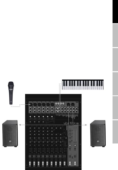
QUICK START GUIDE WITH CABLING EXAMPLE
1.Make sure that the mixer and all devices to be connected to the mixer are turned off.
2.Connect the devices to the mixer using appropriate cables.
3.Adjust the input gain of the channels 1 to 6 and all level controllers channel-LEVEL and MAIN MIX to minimum. Place all equalizer controllers in the central position (stop). Adjust the volume controller on the active loudspeaker to minimum. Turn on the +48 V phantom power on the mixer only if you are using a condenser microphone.
4.Turn on the devices in the following order: Microphone and keyboard (or other source devices), then the mixer and lastly the active speakers.
5.Always adjust the gain control of the channels 1 to 4 or 5/6 and 7/8 so that the peak LED of the corresponding channel only lights up briefly when signal peaks occur. Avoid the permanent lighting of the peak LED by reducing the input gain (Gain).
6.Channels 9/10 and 11/12: Adjust the output level of the keyboard (or other source devices) so that the peak LED above the corresponding channel only lights up briefly when signal peaks occur. Avoid the permanent lighting of the peak LED.
7.Press down on the L-R switch (N 19) of the channels in use.
8.Bring the volume controllers (Fader) of the channels in use and of the sum channel MAIN MIX approximately to the 0 dB mark.
9.Now increase the volume of the active speakers for the incoming signal (e.g.speaking, singing, keyboard) to the desired level.
10.Fine-tuning can now be achieved by adjusting the volume ratios of the channels and by using the equalizer, compressors and effects device as desired.
NOTE: When turning off the devices, please follow these steps: First, set the volume of the active speakers to minimum and turn them off, then the mixer and connected devices can be switched off.
Electronic keyboard
Microphone
Active speaker |
Active speaker |
ENGLISH
FRANCAIS DEUTSCH
ESPAÑOL
POLSKI
ITALIANO
5
ENGLISH
FRANCAIS DEUTSCH
ESPAÑOL
POLSKI
ITALIANO
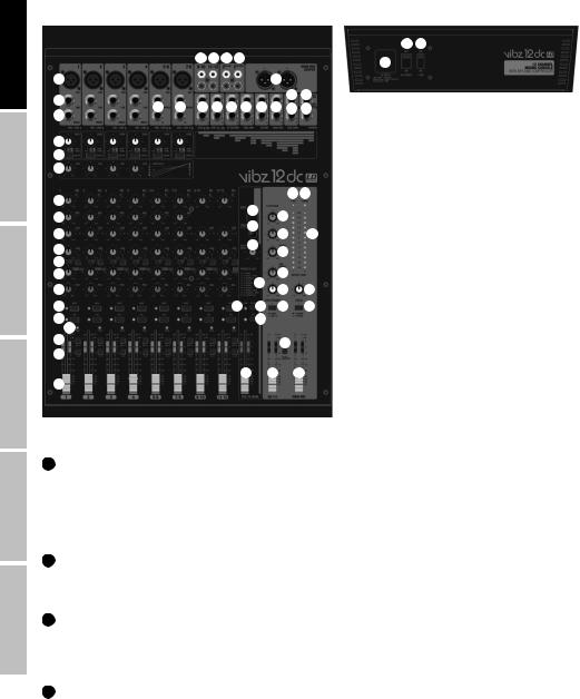
CONNECTIONS, CONTROLS AND INDICATORS
56 53
|
|
|
22 22 30 45 |
|
|
|
55 |
||||
|
|
|
|
|
|
|
|
|
|
||
1 |
|
|
|
|
|
|
|
43 |
|
|
|
2 |
|
|
|
|
|
|
|
|
50 |
42 |
|
21 |
21 |
22 |
22 |
23 |
27 |
48 |
44 |
52 |
26 |
||
3 |
|||||||||||
|
|
|
|
|
|
|
|
|
|
||
4 |
|
|
|
|
|
|
|
|
|
|
|
5 |
|
|
|
|
|
|
|
|
|
|
|
6 |
|
|
|
|
|
|
|
|
|
|
|
7 |
|
|
|
|
|
|
|
|
54 57 |
||
|
|
|
|
|
34 |
|
|
|
|||
8 |
|
|
|
|
|
24 |
|
||||
|
|
|
|
|
33 |
|
|||||
9 |
|
|
|
|
|
25 |
47 |
||||
|
|
|
|
|
40 |
||||||
10 |
|
|
|
|
|
51 |
|
||||
|
|
|
|
|
|
|
|
||||
11 |
|
|
|
|
|
|
|
36 |
|
||
12 |
|
|
|
|
|
|
41 |
|
|||
13 |
|
|
|
|
|
|
28 |
31 |
|||
|
|
|
|
|
|
|
|||||
14 |
|
|
|
|
35 |
38 |
29 |
32 |
|||
15 |
16 |
|
|
|
|
|
39 |
|
|
|
|
|
|
|
|
|
|
|
|
|
|
||
17 |
|
|
|
|
|
|
|
18 |
|
||
|
|
|
|
|
|
|
|
|
|||
19 |
|
|
|
|
|
|
|
|
|
|
|
|
|
|
|
|
|
37 |
|
49 |
46 |
||
20 |
|
|
|
|
|
|
|
|
|
|
|
1 MIC IN 1 - 4 & 5/6 - 7/8
Balanced inputs of the channels 1 to 4, or 5/6 and 7/8 with 3-pin XLR sockets for connecting microphones. Channels 1 to 4 are mono channels, the channels 5/6 and 7/8 can be used as both mono and stereo channels, depending on the incoming signal (XLR and jack L IN = Mono / jack L and R IN = Stereo). A 48 V phantom power supply is available for operating condenser microphones, and it can be switched centrally to the XLR sockets (N° 53). Please set the Gain controller (N 4) to minimum (left stop) before connecting or disconnecting a microphone; and switch on the phantom power only after connecting the microphone, or off before disconnecting.
2 LINE IN CHANNEL 1 - 4
Balanced inputs of the mono channels 1 to 4 with 6.3 mm jack to connect a source device with a line level. Please set the Gain controller (N 4) to minimum (left stop) before connecting or disconnecting jack cables.
3 INSERT CHANNEL 1 - 4
3-pin 6.3 mm jack socket for inserting an external signal processing device (Compressor, Gate, etc.) in the respective mixer channel. A special insert cable is required for the connection (Y-cable, 1 x stereo jack to 2 x mono jack or XLR). The assignment is as follows: TIP = Send, RING = Return, SLEEVE = Masse.
4 GAIN CHANNEL 1 - 7/8
Adjusting the gain of the microphone input from 0 to 50 dB, or the sensitivity of the line input from +15 dBu to -35 dBu. Adjust the Gain controller so that the peak LED of the corresponding channel only lights up briefly when signal peaks occur. Avoid the permanent lighting of the peak LED by reducing the input gain or input sensitivity.
6

5 LOW CUT CHANNEL 1 - 7/8
Low cut filter for suppressing low-frequency signals. Especially with voice and singing transmissions, an activated LOW CUT feature (switch in the down position) can reduce disruptive bass frequencies and thus increase speech intelligibility. The cut-off frequency is 95 Hz.
6 COMPRESSOR
Sliding compressor controller for channels 1 to 4. Depending on the setting, the signal is more or less compressed, i.e., the dynamics of the signal is restricted (controller to the left stop = compressor is disabled, controller to the right stop = maximum compression). The level loss caused by the increasingly stronger compression is automatically compensated by the compressor unit. The use of the compressor can provide for an improved clarity of a singing voice in the mix.
7 EQUALIZER HI CHANNEL 1 - 11/12
Equalizer high band for channels 1 to 11/12 (12 kHz, +/-15 dB). When turned to the left, levels are lowered, when turned to the right, they are raised. In the centre position (resting point), the equalizer is inactive.
8 EQUALIZER MID CHANNEL 1 - 7/8
Equalizer mid band for channels 1 to 7/8 (2.5 kHz, +/-15 dB). When turned to the left, levels are lowered, when turned to the right, they are raised. In the centre position (resting point), the equalizer is inactive.
9 EQUALIZER LOW CHANNEL 1 - 11/12
Equalizer bass band for channels 1 to 11/12 (80 kHz, +/-15 dB). When turned to the left, levels are lowered, when turned to the right, they are raised. In the centre position (resting point), the equalizer is inactive.
10 LEVEL AUX1 PRE / POST CHANNEL 1 - 11/12
Volume controller for adding the signal from channel 1 to 11/12 to an external effects device (effect send, switch 11 POST), or for controlling an active stage monitor (monitor send, switch 11 PRE) Use the line output AUX SEND 1 (N 50) for activation.
11 AUX1 PRE/POST CHANNEL 1 - 11/12
When using AUX 1 to control an external effects device, bring the switch to the up position POST. The control signal is now picked up after the channel level controller (N 20), it is therefore dependent on the latter. To control a stage monitor, bring the switch to the down position PRE. The signal is picked up before the channel level controller (N 20) and the volume of the stage monitor can be adjusted independently of the channel volume.
ENGLISH
FRANCAIS DEUTSCH
ESPAÑOL
12 LEVEL DFX / AUX2 POST CHANNEL 1 - 11/12
Volume controller for adding the signal from channel 1 to 11/12 to the internal digital effects device (effect send, post fader). Use the line output AUX SEND 2 (N 52) for activating an external effect. When using the AUX SEND 2 jack socket, the internal effects device is automatically bypassed, and is therefore not usable.
13 PAN CHANNEL 1 - 4 & BAL CHANNEL 5/6 - 11/12
PAN channel 1 to 4: Using the Panorama controller, position the signal of the corresponding channel in the stereo field of the total signal (Centre position = perception of the signal in the middle of the stereo field). BAL channel 5/6 to 11/12: Use the balance controller to set the relative volume between the left and right part of the connected stereo signal. When only the XLR socket or left socket L (MONO) of the line input of channels 5/6 and 7/8 is in use, the controller performs the function of a Panorama controller.
14 MUTE CHANNEL 1 - 11/12
To mute a channel, press down on the MUTE switch of the corresponding channel. The MUTE LED of the selected channel lights up. When disabling the mute function, the MUTE LED goes out.
15 PFL CHANNEL 1 - 11/12
Press down on the PFL switch (Pre Fader Listen) to be able to listen to the signal of the respective channel regardless of the channel level controller (N 20) using headphones connected to the headphone jack PHONES (N 26). The PFL LED of the selected channel lights up. If the PFL switch is brought to its original position (not down), the PFL LED will go out.
POLSKI
ITALIANO
7

ENGLISH
FRANCAIS DEUTSCH
ESPAÑOL
POLSKI
ITALIANO
16 PEAK LED CHANNEL 1 - 11/12
PEAK channel 1 - 7/8: Once the red Peak LED lights up, the corresponding channel is operating at the distortion limit. Adjust the Gain controller (N 4) so that the peak LED of the corresponding channel only lights up briefly when signal peaks occur. Avoid the permanent lighting of the peak LED by reducing the input gain or input sensitivity. PEAK Channel 9/10 and 11/12: Once the red Peak LED lights up, the corresponding channel is operating at the distortion limit. Adjust the output level of the source device so that the peak LED of the corresponding channel only lights up briefly when signal peaks occur. Avoid the permanent lighting of the peak LED.
17 GR1-2 CHANNEL 1 - 11/12
Press down on the GR1-2 switch to add the corresponding channel to the channel group 1 (PAN/BAL all the way to the left), to the channel group 2 (PAN/BAL all the way to the right), or to both groups of channel groups 1 and 2 in the same proportion (PAN/BAL in central position). The signals of the channels grouped together in one group are routed simultaneously to the corresponding line outputs GR OUT 1 / 2. The total volume of the resulting group is adjusted using the volume controller GR 1-2 (N 49); if the audio signals of the group are to be routed to the MAIN MIX sum channel, press down on the switch GR TO MAIN MIX (N 18).
18 GR TO MAIN MIX
Route the signal of the channel group GR1-2 to the sum channel MAIN MIX by pressing down on the switch.
19 L-R CHANNEL 1 - 11/12
To route an input channel (channel 1 - 11/12) directly to the MAIN MIX sum channel, press down on the L-R switch of the corresponding channel.
20 FADER CHANNEL 1 - 11/12
Volume controller for channels 1 to 11/12. Push the Fader button upwards to increase the volume of the corresponding channel and downwards to decrease it.
21 LINE IN L / R CHANNEL 5/6 - 7/8
Unbalanced inputs for the stereo channels 5/6 and 7/8 with 6.3 mm jacks to connect external devices with line level (e.g. keyboard). If only the left input jack is used (L), the channel will be mono.
22 LINE IN CHANNEL 9/10 - 11/12
Unbalanced line inputs for the stereo channels 9/10 and 11/12. The RCA sockets can be used as an alternative to the jack sockets of the channel.
23 ST RETURN L / R
Unbalanced stereo line input with 6.3 mm jack sockets for connecting an external effects device (left input = mono), or another source device with a line level.
24 ST RETURN TO MAIN
Volume controller for the stereo line input ST RETURN (N 23). The ST RETURN signal is mixed directly into the sum channel MAIN MIX. Turning the dial to the right increases the volume and turning it to the left decreases it.
25 ST RETURN TO AUX1
Volume controller for the stereo line input ST RETURN (N 23). The ST RETURN signal is mixed directly to the AUX 1 output. Turning the dial to the right increases the volume and turning it to the left decreases it.
26 PHONES
Headphone connection with 6.3 mm stereo jack. Output of the sum channel signal MAIN MIX, of the GR1-2 group, or of PFL. The volume can be adjusted via the PHONES / CTRL volume controller (N 28) and is independent of the volume of the MAIN MIX volume controller. Use headphones with a minimum impedance of 30 ohms and make sure that the volume stays at a pleasant level, in order to avoid hearing damage caused by loud noise.
27 CTRL OUT L / R
Unbalanced stereo line output with 6.3 mm jack sockets to connect active monitors etc... Output of the sum channel signal MAIN MIX, of the GR1-2 group, or of PFL. The volume can be adjusted via the PHONES / CTRL volume controller (N 28) and is independent of the volume level of the MAIN MIX and GR1-2 volume controllers.
8

28 PHONES / CTRL
Volume controller for the stereo line output CTRL (N 27) and the headphone output PHONES (N 26). When using headphones, make sure that the volume stays at a pleasant level, in order to avoid hearing damage caused by loud noise.
29 CTRL/PHONES MAIN / GR1-2
To listen to the MAIN MIX sum channel, bring the switch to the up position MAIN; to listen to the group signal, press down on the switch (down position GR1-2).
30 2 TK IN
Unbalanced stereo line input with RCA sockets for connecting an external audio source with line level (e.g. MP3 player).
31 2 TK IN LEVEL
Volume controller for the stereo line input 2 TK IN (N 30). Turning the dial to the right increases the volume and turning it to the left decreases it.
32 2 TK IN TO MAIN / TO CTRL
This switch allows you to route the incoming signal of the stereo line input 2TK IN either to the stereo line output MAIN MIX OUT (not pressed down = TO MAIN), or to the stereo line output CTRL OUT and headphone output PHONES (pressed down = TO CTRL).
33 DFX PRESETS
100 different effects presets are available to you. Use the rotary encoder to select one of the presets as desired (digits in the display N 34 will flash), and then confirm the entry by briefly pressing on the encoder (the digits on the display stop flashing).
34 DFX DISPLAY
The four digit LED display shows the number of the selected effect preset.
35 DFX PEAK LED
Once the red Peak LED lights up, the input of the internal effects device is operating at the distortion limit. Adjust the Effect Send controller DFX SENDS AUX2 (N 36) so that the peak LED only lights up briefly when signal peaks occur.
36 DFX SENDS AUX2
Volume controller for the sum of the signals from the input channels 1 to 11/12 routed via the DFX/AUX2 level controller (N 12).
37 DFX TO MAIN
Volume controller for adding the effects signal of the internal effects device to the sum channel MAIN MIX. Push the Fader button upwards to increase the volume of the effect and downwards to decrease it.
38 DFX MUTE
In order to mute the internal effects device, briefly press the DFX Mute button once, and again to turn mute off. If Mute is active, the DFX Peak LED lights up continuously.
39 DFX PFL
Press down on the PFL switch (Pre Fader Listen) to be able to listen to the effects signal regardless of the channel volume controller DFX TO MAIN (N 37) whilst using headphones connected to the headphone jack PHONES (N 26). The PFL LED lights up. If the PFL switch is brought to its original position (not down), the PFL LED will go out.
40 DFX TO AUX1
Volume controller for adding the effects signal of the internal effects device to AUX 1 output.
41 EFFECTS LIST
List of effects programs for the internal effects device.
ENGLISH
FRANCAIS DEUTSCH
ESPAÑOL
POLSKI
ITALIANO
9

ENGLISH
FRANCAIS DEUTSCH
ESPAÑOL
POLSKI
ITALIANO
42 FOOT SW DFX MUTE
6.3 mm jack socket for connecting a foot switch (pedal) to remotely activate and disable the mute function of the internal effects device (footswitch optional).
43 MAIN MIX OUTPUT
Balanced stereo line output with 3-pin XLR jack sockets to connect an active PA system. Output of the master signal of the mixer.
44 MAIN MIX
Balanced stereo line output with 6.3 mm jack sockets to connect an active PA system. Output of the master signal of the mixer.
45 2 TK OUT
Unbalanced stereo line output with RCA sockets for connecting an external recording device (e.g. laptop). Output of the master signal of the mixer.
46 MAIN MIX
Volume controller for the stereo line outputs MAIN MIX OUTPUT (N 43), MAIN MIX (N 44) and 2 TK OUT (N 45). Push the Fader button upwards to increase the volume, and downwards to decrease it. Before you turn on the power of the connected PA system, set the volume controller to minimum.
47 OUTPUT LEVEL
2 x 12-segment LED level display for visualising the volume level of the stereo sum channel. To avoid distortion, reduce the volume level of the output channel as soon as the red CLIP LED lights up.
48 GR OUT
Unbalanced stereo line output with 6.3 mm jack sockets to connect an active PA system etc... Output of the group signal of the mixer.
49 GR1-2
Volume controller for the stereo line output GR OUT (N 48). Push the Fader button upwards to increase the volume, and downwards to decrease it. Before you turn on the power of the connected PA system, set the volume controller to minimum.
50 AUX SEND 1
Unbalanced mono line output with 6.3 mm jack socket to activate an external effects device (POST Fader), or an active stage monitor (PRE Fader).
51 SENDS AUX1
Volume controller for the sum of the signals from the input channels 1 to 11/12 routed via the AUX1 level controller (N 10).
52 AUX SEND 2
Unbalanced mono line output with 6.3 mm jack sockets to activate an external effects device (POST Fader). When using the AUX SEND 2 jack socket, the internal effects device is automatically bypassed, and is therefore not usable.
53 +48V ON / OFF
+48 V phantom power supply for operating high-quality condenser microphones without own power supply. Press down to select the ON position to turn on the phantom power for the XLR microphone inputs (red LED light N 54 is on), and return to the original OFF position to turn it off (red LED light is off). Turn on the phantom power only after connecting a microphone, or off after disconnecting, and set the volume controller of the channels 1 to 7/8 to minimum before this step.
54 +48V LED
LED display for the +48 V phantom power.
55 POWER CONNECTOR WITH FUSE HOLDER
IEC power socket with built-in fuse holder. An appropriate power cord is included in the delivery. IMPORTANT INFORMATION: Always replace the fuse only with a fuse of the same type with the same rating (printed on the device). If the fuse blows repeatedly, please contact an authorised service centre.
10
56 POWER ON / OFF
On / Off switch for the power supply of the device.
57 POWER LED
Lights up once the system is properly connected to the power mains and switched on.
SPECIFICATIONS
ENGLISH
Model Name:
Product Type:
Type:
Number of Channels:
Mono Channels:
Mono Mic/Line Input Channels:
Mono Mic/Line Input Connections:
Mono Mic Input Type:
Frequency Response Mono Mic Input:
Amplification Range Mono Mic Input:
Channel Crosstalk:
THD Mono Mic Input:
Impedance Mono Mic Input:
S/N Ratio Mono Mic Input:
Mono Line Input Type:
Amplification Range Mono Line Input:
THD Mono Line Input:
Impedance Mono Line Input:
S/N Ratio Mono Line Input:
Mono Channel Equalizer Treble:
Mono Channel Equalizer Mids:
Mono Channel Equalizer Bass:
Channel Insert:
Channel Insert Connections:
Phantom Power:
Low Cut:
Compressor:
Control Elements Channels 1 - 7/8:
Stereo Channels:
Stereo Line Input Channels:
Stereo Line Input Channels:
Stereo Line Input Type:
Frequency Response Stereo Line Input:
Amplification Range Stereo Line Input:
Channel Crosstalk:
THD Stereo Line Input:
Impedance Stereo Line Input:
S/N Ratio Stereo Line Input:
Stereo Channel Equalizer Treble:
Stereo Channel Equalizer Mids:
Stereo Channel Equalizer Bass:
Control Elements Channels 9/10 + 11/12
LDVIBZ12DC |
|
|
analogue mixer |
|
DEUTSCH |
live / home recording |
|
|
|
|
|
12 |
|
|
6 |
|
|
6.3 mm stereo jack, XLR |
|
|
|
|
|
electronically balanced, discreet design |
|
|
10 - 45,000 Hz |
|
FRANCAIS |
0.0058% |
|
|
50 dB |
|
|
90 dB |
|
|
4 kOhm |
|
|
113 dB |
|
|
|
|
|
electronically balanced, discreet design |
|
|
50 dB |
|
ESPAÑOL |
116 dB |
|
|
0.0045% |
|
|
21 kOhm |
|
|
+/-15 dB @ 12 kHz |
|
|
+/-15 dB @ 2.5 kHz |
|
|
|
|
|
+/-15 dB @ 80 Hz |
|
|
Channel 1 - 4 |
|
POLSKI |
6.3 mm stereo jack (TIP= send / RING= return) |
|
|
|
|
|
+48 V DC switchable to XLR inputs |
|
|
95 Hz |
|
|
Channel 1 - 4 |
|
|
Gain, Low Cut, Compressor (channel 1 - 4 only), EQ Hi, EQ Mid, EQ Low, DFX, Pan/ |
|
|
|
|
|
Bal, Channel Fader |
|
|
|
ITALIANO |
|
4 |
|
|
2 x 6.3 mm stereo jack (Lmono, R) 2 x RCA (cinch) |
|
|
|
|
|
unbalanced |
|
|
10 - 45,000 Hz |
|
|
50 dB |
|
|
62 dB |
|
|
0.0045% |
|
|
3.7 kOhm |
|
|
116 dB |
|
|
+/-15 dB @ 12 kHz |
|
|
+/- 15 dB @ 2.5 kHz (not for channel 9/10 - 11/12) |
|
|
+/-15 dB @ 80 Hz |
|
|
EQ Hi, EQ Low, DFX, Bal, Channel Fader |
11 |
|
|
|

ENGLISH
FRANCAIS DEUTSCH
ESPAÑOL
POLSKI
ITALIANO
Main Section: |
|
AUX/Effect Send Channels: |
2 |
AUX/Effect Send Connections: |
6.3 mm stereo jack, unbalanced |
Stereo AUX Return Channels: |
1 |
Stereo AUX Return Connections: |
2 x 6.3 mm stereo jack |
Stereo Tape Output Channel: |
1 x stereo |
Stereo Tape Output Connections: |
2 x RCA (Cinch) |
Stereo Tape Input Channel: |
1 x stereo |
Stereo Tape Input Connections: |
2 x RCA (Cinch) |
Balanced Stereo Main Outputs: |
2 |
Balanced Stereo Main Output Connections: |
2 x 6.3 mm stereo jack (Lmono, R) 2 x XLR male |
Impedance Balanced Stereo Main Outputs: |
120 ohms |
Max. Level Balanced Stereo Main Outputs: |
20 dBV |
Stereo Control Room Outputs: |
1 |
Stereo Control Room Output Connections: |
2 x 6.3 mm jack |
Stereo Groups Outputs (GR OUT): |
1 |
Stereo Groups Output Connections: |
2 x 6.3 mm jack |
Headphone Output: |
1 |
Headphone Output Connections: |
6.3 mm stereo jack |
Minimum Headphone Impedance: |
30 ohms |
Digital Effects Processor: |
yes |
No. of Presets: |
100 |
Foot Switch Connection DFX Mute: |
6.3 mm jack (foot switch optional) |
Control Elements Main Section: |
DFX Presets, DFX Mute, DFX to Main Fader, ST Return, 2 TK In, 2 TK In To Main/To |
|
CTRL, Phones/CTRL Fader, Phantom Power +48V, Main Mix Fader, Power |
Specifications: |
|
Display Elements: |
Channel Peak, Effects Peak, DFX LED Display, Power, Phantom Power, 2 x 12-seg- |
|
ment level display |
Power Connector: |
IEC power socket |
Operating Voltage: |
100 - 240 V AC 50/60 Hz |
Power Consumption (max.): |
30 W |
Fuse: |
T1.6AL / 250 V |
Temperature Range For Operation: |
0°C - +45°C |
Humidity Range For Operation: |
10%rel - 80%rel |
Width: |
440 mm |
Height: |
98 mm |
Depth: |
350 mm |
Weight: |
4.2 kg |
MANUFACTURER´S DECLARATIONS
MANUFACTURER‘S WARRANTY & LIMITATIONS OF LIABILITY
You can find our current warranty conditions and limitations of liability at: http://www.adamhall.com/media/shop/downloads/documents/ manufacturersdeclarations.pdf. To request warranty service for a product, please contact Adam Hall GmbH, Daimler Straße 9, 61267 Neu Anspach / Email: Info@adamhall.com / +49 (0)6081 / 9419-0.
CORRECT DISPOSAL OF THIS PRODUCT
(valid in the European Union and other European countries with a differentiated waste collection system)
 This symbol on the product, or on its documents indicates that the device may not be treated as household waste. This is to avoid environmental damage or personal injury due to uncontrolled waste disposal. Please dispose of this product separately from other waste and have it recycled to promote sustainable economic activity. Household users should contact either the retailer where they purchased this product, or their local government office, for details on where and how they can recycle this item in an environmentally friendly manner. Business users should contact their supplier and check the terms and conditions of the purchase contract. This product should not be mixed with other commercial waste for disposal.
12

DEUTSCH
SIE HABEN DIE RICHTIGE WAHL GETROFFEN!
Dieses Gerät wurde unter hohen Qualitätsanforderungen entwickelt und gefertigt, um viele Jahre einen reibungslosen Betrieb zu gewährleisten. Dafür steht LD Systems mit seinem Namen und der langjährigen Erfahrung als Hersteller hochwertiger Audioprodukte. Bitte lesen Sie diese Bedienungsanleitung sorgfältig, damit Sie Ihr neues Produkt von LD Systems schnell optimal einsetzen können.
Mehr Informationen zu LD SYSTEMS finden Sie auf unserer Internetseite WWW.LD-SYSTEMS.COM
SICHERHEITSHINWEISE
1.Lesen Sie diese Anleitung bitte sorgfältig durch.
2.Bewahren Sie alle Informationen und Anleitungen an einem sicheren Ort auf.
3.Befolgen Sie die Anweisungen.
4.Beachten Sie alle Warnhinweise. Entfernen Sie keine Sicherheitshinweise oder andere Informationen vom Gerät.
5.Verwenden Sie das Gerät nur in der vorgesehenen Art und Weise.
6.Verwenden Sie ausschließlich stabile und passende Stative bzw. Befestigungen (bei Festinstallationen). Stellen Sie sicher, dass Wandhalterungen ordnungsgemäß installiert und gesichert sind. Stellen Sie sicher, dass das Gerät sicher installiert ist und nicht herunterfallen kann.
7.Beachten Sie bei der Installation die für Ihr Land geltenden Sicherheitsvorschriften.
8.Installieren und betreiben Sie das Gerät nicht in der Nähe von Heizkörpern, Wärmespeichern, Öfen oder sonstigen Wärmequellen. Sorgen Sie dafür, dass das Gerät immer so installiert ist, dass es ausreichend gekühlt wird und nicht überhitzen kann.
9.Platzieren Sie keine Zündquellen wie z.B. brennende Kerzen auf dem Gerät.
10.Lüftungsschlitze dürfen nicht blockiert werden.
11.Betreiben Sie das Gerät nicht in unmittelbarer Nähe von Wasser. Bringen Sie das Gerät nicht mit brennbaren Materialien, Flüssigkeiten oder Gasen in Berührung. Direkte Sonneneinstrahlung vermeiden!
12.Sorgen Sie dafür, dass kein Tropfoder Spritzwasser in das Gerät eindringen kann. Stellen Sie keine mit Flüssigkeit gefüllten Behältnisse wie Vasen oder Trinkgefäße auf das Gerät.
13.Sorgen Sie dafür, dass keine Gegenstände in das Gerät fallen können.
14.Betreiben Sie das Gerät nur mit dem vom Hersteller empfohlenen und vorgesehenen Zubehör.
15.Öffnen Sie das Gerät nicht und verändern Sie es nicht.
16.Überprüfen Sie nach dem Anschluss des Geräts alle Kabelwege, um Schäden oder Unfälle, z. B. durch Stolperfallen zu vermeiden.
17.Achten Sie beim Transport darauf, dass das Gerät nicht herunterfallen und dabei möglicherweise Sachund Personenschäden verursachen kann.
18.Wenn Ihr Gerät nicht mehr ordnungsgemäß funktioniert, Flüssigkeiten oder Gegenstände in das Geräteinnere gelangt sind, oder das Gerät anderweitig beschädigt wurde, schalten Sie es sofort aus und trennen es von der Netzsteckdose (sofern es sich um ein aktives Gerät handelt). Dieses Gerät darf nur von autorisiertem Fachpersonal repariert werden.
19.Verwenden Sie zur Reinigung des Geräts ein trockenes Tuch.
20.Beachten Sie alle in Ihrem Land geltenden Entsorgungsgesetze. Trennen Sie bei der Entsorgung der Verpackung bitte Kunststoff und Papier bzw. Kartonagen voneinander.
21.Kunststoffbeutel müssen außer Reichweite von Kindern aufbewahrt werden.
BEI GERÄTEN MIT NETZANSCHLUSS
22.ACHTUNG: Wenn das Netzkabel des Geräts mit einem Schutzkontakt ausgestattet ist, muss es an einer Steckdose mit Schutzleiter angeschlossen werden. Deaktivieren Sie niemals den Schutzleiter eines Netzkabels.
23.Schalten Sie das Gerät nicht sofort ein, wenn es starken Temperaturschwankungen ausgesetzt war (beispielsweise nach dem Transport). Feuchtigkeit und Kondensat könnten das Gerät beschädigen. Schalten Sie das Gerät erst ein, wenn es Zimmertemperatur erreicht hat.
24.Bevor Sie das Gerät an die Steckdose anschließen, prüfen Sie zuerst, ob die Spannung und die Frequenz des Stromnetzes mit den auf dem Gerät angegebenen Werten übereinstimmen. Verfügt das Gerät über einen Spannungswahlschalter, schließen Sie das Gerät nur an die Steckdose an, wenn die Gerätewerte mit den Werten des Stromnetzes übereinstimmen. Wenn das mitgelieferte Netzkabel bzw. der mitgelieferte Netzadapter nicht in Ihre Netzsteckdose passt, wenden Sie sich an Ihren Elektriker.
25.Treten Sie nicht auf das Netzkabel. Sorgen Sie dafür, dass spannungsführende Kabel speziell an der Netzbuchse bzw. am Netzadapter und der Gerätebuchse nicht geknickt werden.
26.Achten Sie bei der Verkabelung des Geräts immer darauf, dass das Netzkabel bzw. der Netzadapter stets frei zugänglich ist. Trennen Sie das Gerät stets von der Stromzuführung, wenn das Gerät nicht benutzt wird, oder Sie das Gerät reinigen möchten. Ziehen Sie Netzkabel und Netzadapter immer am Stecker bzw. am Adapter und nicht am Kabel aus der Steckdose. Berühren Sie Netzkabel und Netzadapter niemals mit nassen Händen.
27.Schalten Sie das Gerät möglichst nicht schnell hintereinander ein und aus, da sonst die Lebensdauer des Geräts beeinträchtigt werden könnte.
28.WICHTIGER HINWEIS: Ersetzen Sie Sicherungen ausschließlich durch Sicherungen des gleichen Typs und Wertes. Sollte eine Sicherung wiederholt auslösen, wenden Sie sich bitte an ein autorisiertes Servicezentrum.
29.Um das Gerät vollständig vom Stromnetz zu trennen, entfernen Sie das Netzkabel bzw. den Netzadapter aus der Steckdose.
30.Wenn Ihr Gerät mit einem verriegelbaren Netzanschluss bestückt ist, muss der passende Gerätestecker entsperrt werden, bevor er entfernt werden kann. Das bedeutet aber auch, dass das Gerät durch ein Ziehen am Netzkabel verrutschen und herunterfallen kann, wodurch Personen verletzt werden und/oder andere Schäden auftreten können. Verlegen Sie Ihre Kabel daher immer sorgfältig.
31.Entfernen Sie Netzkabel und Netzadapter aus der Steckdose bei Gefahr eines Blitzschlags oder wenn Sie das Gerät länger nicht verwenden.
ACHTUNG
Entfernen Sie niemals die Abdeckung, da sonst das Risiko eines elektrischen Schlages besteht. Im

 Inneren des Geräts befinden sich keine Teile, die vom Bediener repariert oder gewartet werden können.
  Lassen Sie Wartung und Reparaturen ausschließlich von qualifiziertem Servicepersonal durchführen.
ENGLISH
FRANCAIS DEUTSCH
ESPAÑOL
POLSKI
ITALIANO
13

ENGLISH
FRANCAIS DEUTSCH
ESPAÑOL
POLSKI
ITALIANO
Das gleichseitige Dreieck mit Blitzsymbol warnt vor nichtisolierten, gefährlichen Spannungen im Geräteinneren, die einen elektrischen Schlag verursachen können.
Das gleichseitige Dreieck mit Ausrufungszeichen kennzeichnet wichtige Bedienungsund Wartungshinweise.
Warnung! Dieses Symbol kennzeichnet heiße Oberflächen. Während des Betriebs können bestimmte Teile des Gehäuses heiß werden. Berühren oder transportieren Sie das Gerät nach einem Einsatz erst nach einer Abkühlzeit von mindestens 10 Minuten.
ACHTUNG HOHE LAUTSTÄRKEN BEI AUDIOPRODUKTEN!
Dieses Gerät ist für den professionellen Einsatz vorgesehen. Der kommerzielle Betrieb dieses Geräts unterliegt den jeweils gültigen nationalen Vorschriften und Richtlinien zur Unfallverhütung. Als Hersteller ist Adam Hall gesetzlich verpflichtet, Sie ausdrücklich auf mögliche Gesundheitsrisiken hinzuweisen. Gehörschäden durch hohe Lautstärken und Dauerbelastung: Bei der Verwendung dieses Produkts können hohe Schalldruckpegel (SPL) erzeugt werden, die bei Künstlern, Mitarbeitern und Zuschauern zu irreparablen Gehörschäden führen können. Vermeiden Sie länger anhaltende Belastung durch hohe Lautstärken über 90 dB.
EINFÜHRUNG
LDVIBZ12DC - 12-Kanal Mixer mit digitaler Effektsektion und Compressor
Der VIBZ 12 DC ist ein vielseitig einsetzbares Mischpult mit sechs symmetrischen Mikrofoneingängen, die über hochwertige Vorverstärker, Low-Cut-Filter, einen effektiven 3-Band-EQ mit praxisgerecht gewählten Mittenfrequenzen und zuschaltbare Phantomspeisung verfügen. Vier Mikrofonkanäle können mit dem eingebauten Compressor für eine wirkungsvolle Dynamikregelung separat bearbeitet werden,
zwei weitere können alternativ als Stereo-Line-Kanäle benutzt werden. Die übrigen Stereokanäle sind mit 2-Band-EQs ausgestattet. Die Mastersektion des Mischpults beinhaltet u.a. zwei Effektwege, symmetrische XLR-Ausgänge, Gruppenund Monitorausgänge sowie einen Kopfhöreranschluß. Der VIBZ 12 DC besitzt zudem RCA-Anschlüsse für Aufnahmeund Abspielgeräte und eine digitale Effeksektion mit 100 Presets. Mit wichtigen Ausstattungs-Details wie der PFL-Funktion oder Mute-Tastern und seinem natürlichen, transparenten Klang ist der VIBZ 12 DC die perfekte Wahl für den Live-Einsatz, Installationen und anspruchsvolle Homerecording-Anwendungen.
14
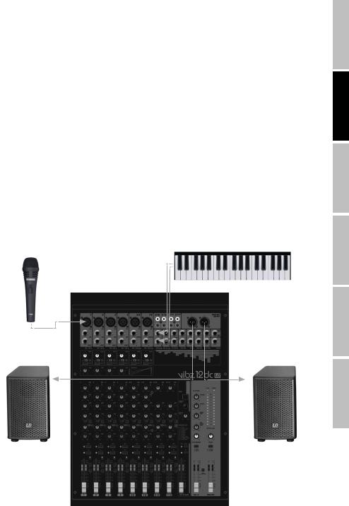
SCHNELLSTARTANLEITUNG MIT VERKABELUNGSBEISPIEL
1.Achten Sie darauf, dass das Mischpult und alle Geräte, die am Mischpult angeschlossen werden sollen, ausgeschaltet sind.
2.Schließen Sie die Geräte mit geeigneten Kabeln am Mischpult an.
3.Stellen Sie die Vorverstärkung der Kanäle 1 bis 6 und alle Pegelsteller Kanal-LEVEL und MAIN MIX auf Minimum. Bringen Sie die Regler aller Equalizer in Mittelstellung (Rastpunkt). Stellen Sie die Lautstärkeregler der aktiven Lautsprecher auf Minimum. Schalten Sie die +48V Phantomspeisung des Mischpults nur ein, wenn Sie ein Kondensatormikrofon verwenden.
4.Schalten Sie die Geräte in der folgenden Reihenfolge ein: Mikrofon und Keyboard (oder andere Zuspielgeräte), das Mischpult und zuletzt die aktiven Lautsprecher.
5.Stellen Sie die Gain-Regler der Kanäle 1 bis 4, bzw. 5/6 und 7/8 so ein, dass die Peak-LED des entsprechenden Kanals nur bei Pegelspitzen des anliegenden Signals kurz aufleuchtet. Vermeiden Sie permanentes Leuchten der Peak-LED durch Reduzieren der Eingangsvorverstärkung (Gain).
6.Kanäle 9/10 und 11/12: Stellen Sie den Ausgangspegel des Keyboards (oder andere Zuspielgeräte) so ein, dass die Peak-LED des entsprechenden Kanals nur bei Pegelspitzen des anliegenden Signals kurz aufleuchtet. Vermeiden Sie permanentes Leuchten der Peak-LED.
7.Bringen Sie den Schalter L-R (Nr. 19) der verwendeten Kanäle in die heruntergedrückte Position.
8.Bringen Sie die Pegelsteller (Fader) der verwendeten Kanäle und des Summenkanals MAIN MIX ungefähr auf die 0 dB Markierung.
9.Erhöhen Sie bei anliegendem Signal (z.B. Sprache, Gesang, Keyboard) nun die Lautstärke der aktiven Lautsprecher auf den gewünschten Pegel.
10.Die Feinabstimmung durch das Einstellen der Lautstärkenverhältnisse der Kanäle und die Verwendung der Equalizer, Compressoren und des Effektgeräts kann nun nach Wunsch durchgeführt werden.
HINWEIS: Beim Ausschalten der Geräte beachten Sie bitte folgende Schritte: Stellen Sie zuerst die Lautstärke der aktiven Lautsprecher auf Minimum und schalten Sie aus, danach können das Mischpult und die angeschlossenen Geräte ausgeschaltet werden.
elektronisches Keyboard
Mikrofon
ENGLISH
FRANCAIS DEUTSCH
ESPAÑOL
POLSKI
Aktivlautsprecher |
Aktivlautsprecher |
ITALIANO
15
ENGLISH
FRANCAIS DEUTSCH
ESPAÑOL
POLSKI
ITALIANO
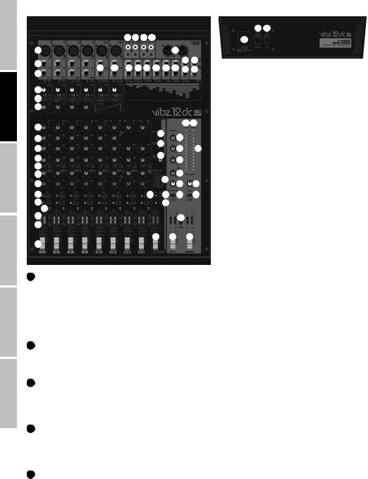
ANSCHLÜSSE, BEDIENUND ANZEIGEELEMENTE
56 53
|
|
|
22 22 30 45 |
|
|
|
55 |
||||
|
|
|
|
|
|
|
|
|
|
||
1 |
|
|
|
|
|
|
|
43 |
|
|
|
2 |
|
|
|
|
|
|
|
|
50 |
42 |
|
21 |
21 |
22 |
22 |
23 |
27 |
48 |
44 |
52 |
26 |
||
3 |
|||||||||||
|
|
|
|
|
|
|
|
|
|
||
4 |
|
|
|
|
|
|
|
|
|
|
|
5 |
|
|
|
|
|
|
|
|
|
|
|
6 |
|
|
|
|
|
|
|
|
|
|
|
7 |
|
|
|
|
|
|
|
|
54 57 |
||
|
|
|
|
|
34 |
|
|
|
|||
8 |
|
|
|
|
|
24 |
|
||||
|
|
|
|
|
33 |
|
|||||
9 |
|
|
|
|
|
25 |
47 |
||||
|
|
|
|
|
40 |
||||||
10 |
|
|
|
|
|
51 |
|
||||
|
|
|
|
|
|
|
|
||||
11 |
|
|
|
|
|
|
|
36 |
|
||
12 |
|
|
|
|
|
|
41 |
|
|||
13 |
|
|
|
|
|
|
28 |
31 |
|||
|
|
|
|
|
|
|
|||||
14 |
|
|
|
|
35 |
38 |
29 |
32 |
|||
15 |
16 |
|
|
|
|
|
39 |
|
|
|
|
|
|
|
|
|
|
|
|
|
|
||
17 |
|
|
|
|
|
|
|
18 |
|
||
|
|
|
|
|
|
|
|
|
|||
19 |
|
|
|
|
|
|
|
|
|
|
|
|
|
|
|
|
|
37 |
|
49 |
46 |
||
20 |
|
|
|
|
|
|
|
|
|
|
|
1 MIC IN 1 - 4 & 5/6 - 7/8
Symmetrische Eingänge der Kanäle 1 bis 4, bzw. 5/6 und 7/8 mit 3-Pol XLR-Buchsen zum Anschließen von Mikrofonen. Die Kanäle 1 bis 4 sind Mono-Kanäle, die Kanäle 5/6 und 7/8 können je nach Belegung sowohl als Monoals auch als Stereo-Kanäle verwendet werden (XLR und Klinke L IN = Mono / Klinke L und R IN = Stereo) . Für den Betrieb von Kondensator-Mikrofonen steht eine 48V Phantomspeisung zur Verfügung, die zentral auf die XLR-Buchsen zugeschaltet werden kann (Nr. 53). Vor dem Einbzw. Ausstecken von Mikrofonen stellen Sie den Gain-Regler (Nr. 4) bitte auf ein Minimum (Linksanschlag) und schalten die Phantomspeisung erst nach dem Anschließen eines Mikrofons ein, bzw. vor dem Ausstecken aus.
2 LINE IN KANAL 1 - 4
Symmetrische Eingänge der Mono-Kanäle 1 bis 4 mit 6,3mm Klinkenbuchse zum Anschließen eines Zuspielgeräts mit Line-Pegel. Vor dem Einbzw. Ausstecken von Klinkenkabeln stellen Sie den Gain-Regler (Nr. 4) bitte auf ein Minimum (Linksanschlag).
3 INSERT KANAL 1 - 4
3-polige 6,3mm Klinkenbuchse zum Einschleifen eines externen signalverarbeitenden Geräts (Compressor, Gate usw.) in den entsprechenden Mischpult-Kanal. Für die Verbindung wird ein spezielles Insert-Kabel benötigt (Y-Kabel, 1x Stereo-Klinke auf 2x Mono-Klinke, bzw. XLR). Die Belegung der Buchse ist wie folgt: TIP = Send, RING = Return, SLEEVE = Masse.
4 GAIN KANAL 1 - 7/8
Justieren der Vorverstärkung des Mikrofon-Eingangs von 0 bis 50 dB, bzw. der Empfindlichkeit des Line-Eingangs von +15 bis -35 dBu. Stellen Sie den Gain-Regler so ein, dass die Peak-LED des entsprechenden Kanals nur bei Pegelspitzen des anliegenden Signals kurz aufleuchtet. Vermeiden Sie permanentes Leuchten der Peak-LED durch Reduzierung der Eingangsvorverstärkung, bzw. der Eingangsempfindlichkeit.
5 LOW CUT KANAL 1 - 7/8
Tiefensperre für die Unterdrückung tieffrequenter Signalanteile. Vor allem bei Sprachund Gesangsübertragung kann ein aktivierter LOW CUT (Schalter in heruntergedrückter Position) störende Bassfrequenzen absenken und somit die Textverständlichkeit steigern. Die Grenzfrequenz liegt bei 95 Hz.
16

6 COMPRESSOR
Stufenlos regelbarer Compressor für die Kanäle 1 bis 4. Je nach Einstellung wird das anliegende Signal weniger, oder stärker verdichtet, d.h., die Dynamik des Signals wird eingeschränkt (Linksanschlag des Reglers = Compressor deaktiviert, Rechtsanschlag = maximale Verdichtung). Der durch zunehmend stärkerer Verdichtung größer werdende Pegelverlust wird von der Compressor-Einheit automatisch ausgeglichen. Der Einsatz des Compressors kann z.B. für eine verbesserte Durchsetzung einer Gesangsstimme im Mix sorgen.
7 EQUALIZER HI KANAL 1 - 11/12
Equalizer Höhenband für die Kanäle 1 bis 11/12 (12 kHz, +/-15 dB). Nach links gedreht werden Höhen abgesenkt, nach rechts gedreht angehoben. In Mittelstellung (Rastpunkt) ist der Equalizer inaktiv.
8 EQUALIZER MID KANAL 1 - 7/8
Equalizer Mittenband für die Kanäle 1 bis 7/8 (2,5 kHz, +/-15 dB). Nach links gedreht werden Mitten abgesenkt, nach rechts gedreht angehoben. In Mittelstellung (Rastpunkt) ist der Equalizer inaktiv.
9 EQUALIZER LOW KANAL 1 - 11/12
Equalizer Bassband für die Kanäle 1 bis 11/12 (80 Hz, +/-15 dB). Nach links gedreht werden Bässe abgesenkt, nach rechts gedreht angehoben. In Mittelstellung (Rastpunkt) ist der Equalizer inaktiv.
10 LEVEL AUX1 PRE / POST KANAL 1 - 11/12
Pegelsteller für die Zumischung des Signals von Kanal 1 bis 11/12 auf ein externes Effektgerät (Effekt Send, Schalter 11 POST), oder für die Ansteuerung eines aktiven Bühnenmonitors (Monitor Send, Schalter 11 PRE). Verwenden Sie den Line-Ausgang AUX SEND 1 (Nr. 50) zur Ansteuerung.
11 AUX1 PRE/POST KANAL 1 - 11/12
Wenn Sie AUX 1 zur Ansteuerung eines externen Effektgeräts verwenden, bringen Sie den Schalter in die nicht heruntergedrückte Position POST. Das Ansteuerungsignal wird nun hinter dem Kanal-Pegelsteller (Nr. 20) abgegriffen, ist also abhängig davon. Zur Ansteuerung eines Bühnenmonitors, bringen Sie den Schalter in die heruntergedrückte Position PRE. Das Signal wird nun vor dem Kanal-Pegelsteller (Nr. 20) abgegriffen und die Lautstärke des Bühnenmonitors kann unabhängig von der Kanal-Lautstärke eingestellt werden.
12 LEVEL DFX / AUX2 POST KANAL 1 - 11/12
Pegelsteller für die Zumischung des Signals von Kanal 1 bis 11/12 auf das interne digitale Effektgerät (Effekt Send, Post Fader). Verwenden Sie den Line-Ausgang AUX SEND 2 (Nr. 52) zur Ansteuerung eines externen Effektgeräts. Bei der Verwendung der AUX SEND 2-Klinkenbuchse, wird das interne Effektgerät automatisch umgangen und ist somit nicht verwendbar.
13 PAN CHANNEL 1 - 4 & BAL KANAL 5/6 - 11/12
PAN Kanal 1 bis 4: Mit Hilfe des Panorama-Reglers positionieren Sie das Signal des entsprechenden Kanals im Stereofeld des Gesamtsignals (Mittelstellung = Wahrnehmung des Signals in der Mitte des Stereofelds). BAL Kanal 5/6 bis 11/12: Mit Hilfe des Balance-Reglers stellen Sie das Lautstärkenverhältnis zwischen dem linken und rechten Anteil des anliegenden Stereo-Signals ein. Sobald die XLR-Buchse, bzw. lediglich die linke Buchse L (MONO) des Line-Eingangs der Kanäle 5/6 und 7/8 belegt sind, erfüllt der Regler die Funktion eines Panorama-Reglers.
ENGLISH
FRANCAIS DEUTSCH
ESPAÑOL
POLSKI
14 MUTE KANAL 1 - 11/12
Um einen Kanal stummzuschalten, bringen Sie den MUTE-Schalter des entsprechenden Kanals in die heruntergedrückte Position. Gleichzeitig beginnt die MUTE-LED des Kanals zu leuchten. Beim Deaktivieren der Stummschaltung, erlischt die MUTE-LED.
15 PFL KANAL 1 - 11/12
Bringen Sie den PFL-Schalter (Pre Fader Listen) in die heruntergedrückte Position, um das Signal des entsprechenden Kanals unabhängig vom Kanal-Pegelsteller (Nr. 20) mit Hilfe eines am Kopfhörer-Ausgang PHONES (Nr. 26) angeschlossenen Kopfhörers separat vorhören zu können. Gleichzeitig beginnt die PFL-LED des Kanals zu leuchten. Wird der PFL-Schalter in die Ursprungsposition gebracht, erlischt die PFL-LED.
16 PEAK LED KANAL 1 - 11/12
PEAK Kanal 1 - 7/8: Sobald die rote Peak-LED aufleuchtet, wird der Eingang des entsprechenden Kanals an der Verzerrungsgrenze betrieben. Stellen Sie den Gain-Regler (Nr. 4) so ein, dass die Peak-LED nur bei Pegelspitzen des anliegenden Signals kurz aufleuchtet. Vermeiden Sie permanentes Leuchten der Peak-LED durch Reduzierung der Eingangsvorverstärkung, bzw. der Eingangsempfindlichkeit. PEAK Kanal 9/10 und 11/12: Sobald die rote Peak-LED aufleuchtet, wird der Eingang des entsprechenden Kanals an der Verzerrungsgrenze betrieben. Stellen Sie den Ausgangspegel des Zuspielgeräts so ein, dass die Peak-LED nur bei Pegelspitzen des anliegenden Signals kurz aufleuchtet.
Vermeiden Sie permanentes Leuchten der Peak-LED.
17
ITALIANO

ENGLISH
FRANCAIS DEUTSCH
ESPAÑOL
POLSKI
ITALIANO
17 GR1-2 KANAL 1 - 11/12
Bringen Sie den GR1-2-Schalter in die heruntergedrückte Position, um den entsprechenden Kanal zur Kanal-Gruppe 1 (PAN/BAL auf Linksanschlag), zur Kanal-Gruppe 2 (PAN/BAL auf Rechtsanschlag), oder mit den gleichen Signalanteilen zu beiden Kanal-Gruppen 1 und 2 (PAN/ BAL in Mittelstellung) hinzuzufügen. Gleichzeitig werden die Signale der in eine Gruppe zusammengefassten Kanäle auf die entsprechenden Line-Ausgänge GR OUT 1 / 2 geroutet. Die Gesamtlautstärke der so gebildeten Gruppe wird mit Hilfe des Pegelstellers GR 1-2 (Nr. 49) eingestellt, sollen die Audio-Signale der Gruppe auf den Summenkanal MAIN MIX geroutet werde, bringen Sie den Schalter GR TO MAIN MIX (Nr.18) in die heruntergedrückte Position.
18 GR TO MAIN MIX
Routen Sie das Signal der Kanal-Gruppe GR1-2 auf den Summenkanal MAIN MIX, indem Sie den Schalter in die heruntergedrückte Position bringen.
19 L-R KANAL 1 - 11/12
Um einen Eingangskanal (Kanal 1 - 11/12) direkt auf den Summenkanal MAIN MIX zu routen, bringen Sie den Schalter L-R des entsprechenden Kanals in die heruntergedrückte Position.
20 FADER KANAL1 - 11/12
Pegelsteller für die Kanäle 1 bis 11/12. Schieben Sie den Fader-Knopf nach oben, um die Lautstärke des entsprechenden Kanals anzuheben und nach unten, um sie zu verringern.
21 LINE IN L / R KANAL 5/6 - 7/8
Unsymmetrische Eingänge der Stereo-Kanäle 5/6 und 7/8 mit 6,3mm Klinken-Buchsen zum Anschließen von Zuspielgeräten mit Line-Pegel (z.B. Keyboard). Wird lediglich die Eingangsbuchse links (L) belegt, wird der Kanal Mono betrieben.
22 LINE IN KANAL 9/10 - 11/12
Unsymmetrische Line-Eingänge der Stereo Kanäle 9/10 und 11/12. Die Cinch-Buchsen können alternativ zu den Klinken-Buchsen des Kanals verwendet werden.
23 ST RETURN L / R
Unsymmetrischer Stereo-Line-Eingang mit 6,3mm Klinkenbuchsen für den Anschluss eines externen Effektgeräts (Eingang links = Mono), oder eines anderen Zuspielgeräts mit Line-Pegel.
24 ST RETURN TO MAIN
Pegelsteller für den Stereo-Line-Eingang ST RETURN (Nr. 23). Das ST RETURN-Signal wird direkt auf den Summenkanal MAIN MIX gemischt. Nach links gedreht verringert sich, nach rechts gedreht erhöht sich die Lautstärke.
25 ST RETURN TO AUX1
Pegelsteller für den Stereo-Line-Eingang ST RETURN (Nr. 23). Das ST RETURN-Signal wird direkt auf den Ausspielweg AUX1 gemischt. Nach links gedreht verringert sich, nach rechts gedreht erhöht sich die Lautstärke.
26 PHONES
Kopfhöreranschluss mit 6,3mm Stereo-Klinkenbuchse. Ausgabe des Signals des Summenkanals MAIN MIX, der Gruppe GR1-2, oder von PFL. Die Lautstärkeneinstellung erfolgt über den Pegelsteller PHONES / CTRL (Nr. 28) und ist unabhängig von der Lautstärkeneinstellung des Pegelstellers MAIN MIX. Verwenden Sie Kopfhörer mit einer minimalen Impedanz von 30 Ohm und achten darauf, die Lautstärke auf einem angenehmen Pegel zu halten, um Gehörschäden durch laute Geräusche zu vermeiden.
27 CTRL OUT L / R
Unsymmetrischer Stereo-Line-Ausgang mit 6,3mm Klinkenbuchsen zum Anschließen von aktiven Monitoren etc.. Ausgabe des Signals des Summenkanals MAIN MIX, der Gruppe GR1-2, oder von PFL. Die Lautstärkeneinstellung erfolgt über den Pegelsteller PHONES / CTRL (Nr. 28) und ist unabhängig von der Lautstärkeneinstellung der Pegelsteller MAIN MIX und GR1-2.
28 PHONES / CTRL
Pegelsteller für den Stereo-Line-Ausgang CTRL (Nr. 27) und den Kopfhörer-Ausgang PHONES (Nr. 26). Besonders bei der Verwendung von Kopfhörern, achten Sie darauf, die Lautstärke auf einem angenehmen Pegel zu halten, um Gehörschäden durch laute Geräusche zu vermeiden.
18

29 CTRL/PHONES MAIN / GR1-2
Zum Abhören des Summenkanals MAIN MIX bringen Sie den Schalter in die nicht heruntergedrückte Position MAIN, zum Abhören des Gruppen-Signals in die heruntergedrückte Position GR1-2.
30 2 TK IN
Unsymmetrischer Stereo-Line-Eingang mit Cinch-Buchsen zum Anschließen eines Zuspielgeräts mit Line-Pegel (z.B. MP3-Player).
31 2 TK IN LEVEL
Pegelsteller für den Stereo-Line-Eingang 2 TK IN (Nr. 30). Nach links gedreht verringert sich, nach rechts gedreht erhöht sich die Lautstärke.
32 2 TK IN TO MAIN / TO CTRL
Dieser Umschalter ermöglicht es, das am Stereo-Line-Eingang 2TK IN anliegende Signal wahlweise auf die Stereo-Line-Ausgänge MAIN MIX OUT, CTRL OUT und den Kopfhörerausgang PHONES (nicht heruntergedrückte Position TO MAIN), oder ausschließlich auf den Ste- reo-Line-Ausgang CTRL OUT und den Kopfhörerausgang PHONES zu routen (heruntergedrückte Position TO CTRL).
33 DFX PRESETS
100 verschiedene Effekt-Presets stehen Ihnen zur Verfügung. Verwenden Sie den Drehgeber, um wunschgemäß eines der Presets auszuwählen (Ziffern im Display Nr. 34 blinken) und bestätigen dann die Eingabe durch kurzes Drücken auf den Drehgeber (das Blinken der Ziffern im Display stoppt).
34 DFX DISPLAY
Das 2-stellige LED-Display zeigt die Nummer des ausgewählten Effekt-Presets an.
35 DFX PEAK LED
Sobald die rote Peak-LED aufleuchtet, wird der Eingang des internen Effektgeräts an der Verzerrungsgrenze betrieben. Stellen Sie den Effekt-Send-Pegelsteller DFX SENDS AUX2 (Nr. 36) so ein, dass die Peak-LED nur bei Pegelspitzen des anliegenden Signals kurz aufleuchtet.
36 DFX SENDS AUX2
Pegelsteller für das Gesamt-Signal der über die DFX/AUX2 Pegelsteller (Nr. 12) ausgespielten Signale der Eingangskanäle 1 bis 11/12.
37 DFX TO MAIN
Pegelsteller für die Zumischung des Effekt-Signals des internen Effektgeräts auf den Summenkanal MAIN MIX. Schieben Sie den Fa- der-Knopf nach oben, um die Effekt-Lautstärke anzuheben und nach unten, um sie zu verringern.
38 DFX MUTE
Um das interne Effektgerät stummzuschalten, drücken Sie kurz auf den DFX Mute-Taster und nochmals, um die Stummschaltung zu deaktivieren. Ist die Stummschaltung aktiv, leuchtet die DFX Peak-LED permanent.
39 DFX PFL
Bringen Sie den PFL-Schalter (Pre Fader Listen) in die heruntergedrückte Position, um das Effekt-Signal unabhängig vom Pegelsteller DFX TO MAIN (Nr. 37) mit Hilfe eines am Kopfhörer-Ausgang PHONES (Nr. 26) angeschlossenen Kopfhörers separat vorhören zu können. Gleichzeitig beginnt die PFL-LED zu leuchten. Wird der PFL-Schalter in die Ursprungsposition gebracht, erlischt die PFL-LED.
40 DFX TO AUX1
Pegelsteller für die Zumischung des Effekt-Signals des internen Effektgeräts auf den Ausspielweg AUX 1.
41 EFFECTS LIST
Liste der Effektprogramme des internen Effektgeräts.
42 FOOT SW DFX MUTE
6,3mm Klinkenbuchse zum Anschließen eines Fußtasters (Schließer) um die Stummschaltung des internen Effektgeräts ferngesteuert zu aktivieren und deaktivieren (Fußtaster optional).
ENGLISH
FRANCAIS DEUTSCH
ESPAÑOL
POLSKI
ITALIANO
19

ENGLISH
FRANCAIS DEUTSCH
ESPAÑOL
POLSKI
ITALIANO
43 MAIN MIX OUTPUT
Symmetrischer Stereo-Line-Ausgang mit 3-Pol XLR-Buchsen zum Anschließen einer aktiven Beschallungsanlage. Ausgabe des Summen-Si- gnals des Mischpults.
44 MAIN MIX
Symmetrischer Stereo-Line-Ausgang mit 6,3mm Klinkenbuchsen zum Anschließen einer aktiven Beschallungsanlage. Ausgabe des Sum- men-Signals des Mischpults.
45 2 TK OUT
Unsymmetrischer Stereo-Line-Ausgang mit Cinch-Buchsen zum Anschließen eines Aufnahmegeräts (z.B. Laptop). Ausgabe des Summen-Si- gnals des Mischpults.
46 MAIN MIX
Pegelsteller für die Stereo-Line-Ausgänge MAIN MIX OUTPUT (Nr. 43), MAIN MIX (Nr. 44) und 2 TK OUT (Nr. 45). Schieben Sie den Fa- der-Knopf nach oben, um die Lautstärke anzuheben und nach unten, um sie zu verringern. Stellen Sie vor dem Einschalten der angeschlossenen Beschallungsanlage den Pegelsteller auf Minimum.
47 OUTPUT LEVEL
2x 12-Segment LED-Pegel-Anzeige für die Visualisierung des Pegels im Stereo-Summenkanal. Um Verzerrungen zu vermeiden, reduzieren Sie den Ausgangspegel, sobald die rote CLIP-LED aufleuchtet.
48 GR OUT
Unsymmetrischer Stereo-Line-Ausgang mit 6,3mm Klinkenbuchsen zum Anschließen einer aktiven Beschallungsanlage etc.. Ausgabe des Gruppen-Signals des Mischpults.
49 GR1-2
Pegelsteller für den Stereo-Line-Ausgang GR OUT (Nr. 48). Schieben Sie den Fader-Knopf nach oben, um die Lautstärke anzuheben und nach unten, um sie zu verringern. Stellen Sie vor dem Einschalten der angeschlossenen Beschallungsanlage den Pegelsteller auf Minimum.
50 AUX SEND 1
Unsymmetrischer Mono-Line-Ausgang mit 6,3mm Klinkenbuchse zum Ansteuern eines externen Effektgeräts (POST Fader), oder aktiven Bühnenmonitors (PRE Fader).
51 SENDS AUX1
Pegelsteller für das Gesamt-Signal der über die AUX1 Pegelsteller (Nr. 10) ausgespielten Signale der Eingangskanäle 1 bis 11/12.
52 AUX SEND 2
Unsymmetrischer Mono-Line-Ausgang mit 6,3mm Klinkenbuchse zum Ansteuern eines externen Effektgeräts (POST Fader). Bei der Verwendung der AUX SEND 2-Klinkenbuchse, wird das interne Effektgerät automatisch umgangen und ist somit nicht verwendbar.
53 +48V ON / OFF
+48V Phantomspeisung für den Betrieb von Kondensatormikrofonen ohne eigene Spannungsversorgung. Bringen Sie den Schalter in die Position ON, um die Phantomspeisung für die XLR Mikrofon-Eingänge einzuschalten (rote Anzeige-LED Nr. 54 leuchtet) und in die nicht heruntergedrückte Position OFF, um sie auszuschalten (rote Anzeige-LED erlischt). Schalten Sie die Phantomspeisung erst nach dem Anschließen eines Mikrofons ein, bzw. vor dem Ausstecken aus und stellen vor einem Schaltvorgang die Pegelsteller der Kanäle 1 bis 7/8 auf Minimum.
54 +48V LED
Anzeige-LED für die +48V Phantomspeisung.
55 NETZBUCHSE UND SICHERUNGSHALTER
IEC Netzbuchse mit integriertem Sicherungshalter. Ein geeignetes Netzkabel befindet sich im Lieferumfang. WICHTIGER HINWEIS: Ersetzen Sie die Sicherung ausschließlich durch eine Sicherung des gleichen Typs und mit gleichen Werten entsprechend des Aufdrucks auf dem Gerät! Sollte die Sicherung wiederholt auslösen, wenden Sie sich bitte an ein autorisiertes Servicezentrum.
20
56 POWER ON / OFF
Ein- / Ausschalter für die Spannungszufuhr des Mischpults.
57 POWER LED
Die Power-LED leuchtet, sobald das Gerät korrekt am Stromnetz angeschlossen und eingeschaltet ist.
TECHNISCHE DATEN
Modellbezeichnung: |
LDVIBZ12DC |
|
Produktart: |
Analoges Mischpult |
|
Typ: |
Live / Home recording |
|
Anzahl Kanäle: |
12 |
|
Mono Kanäle: |
|
|
Mono Mic/Line Eingangskanäle: |
6 |
|
Mono Mic/Line Eingangsanschlüsse: |
6,3 mm Stereoklinke, XLR |
|
Mono Mic Eingangstyp: |
elektronisch symmetriert, diskreter Aufbau |
|
Frequenzgang Mono Mic Eingang: |
10 - 45.000Hz |
|
Verstärkungsbereich Mono Mic Eingang: |
50dB |
|
Kanalübersprechung: |
90 dB |
|
THD Mono Mic Eingang: |
0.0058% |
|
Impedanz Mono Mic Eingang: |
4kOhm |
|
S/N Ratio Mono Mic Eingang: |
113dB |
|
Mono Line Eingangstyp: |
elektronisch symmetriert, diskreter Aufbau |
|
Verstärkungsbereich Mono Line Eingang: |
50dB |
|
THD Mono Line Eingang: |
0.0045% |
|
Impedanz Mono Line Eingang: |
21k Ohm |
|
S/N Ratio Mono Line Eingang: |
116dB |
|
Mono Kanal Equalizer Höhen: |
+/- 15dB @ 12kHz |
|
Mono Kanal Equalizer Mitten: |
+/- 15dB @ 2,5kHz |
|
Mono Kanal Equalizer Bässe: |
+/- 15dB @ 80Hz |
|
Kanal-Insert: |
Kanal 1 - 4 |
|
Kanal-Insert Anschlüsse: |
6,3 mm Stereoklinke (TIP= send / RING= return) |
|
Phantomspeisung: |
+48V DC schaltbar auf XLR Inputs |
|
Low Cut: |
95Hz |
|
Compressor: |
Kanal 1 - 4 |
|
Bedienelemente Kanal 1 - 7/8: |
Gain, Low Cut, Compressor (nur Kanal 1 - 4), EQ Hi, EQ Mid, EQ Low, DFX, Pan/Bal, |
|
Kanal-Fader |
||
|
||
Stereo Kanäle: |
|
|
Stereo Line Eingangskanäle: |
4 |
|
Stereo Line Eingangsanschlüsse: |
2x 6,3 mm Stereoklinke (Lmono, R) 2x RCA (Chinch) |
|
Stereo Line Eingangstyp: |
Unbalanced |
|
Frequenzgang Stereo Line Eingang: |
10 - 45.000Hz |
|
Verstärkungsbereich Stereo Line Eingang: |
50dB |
|
Kanalübersprechung: |
62 dB |
|
THD Stereo Line Eingang: |
0.0045% |
|
Impedanz Stereo Line Eingang: |
3,7kOhm |
|
S/N Ratio Stereo Line Eingang: |
116dB |
|
Stereo Kanal Equalizer Höhen: |
+/- 15dB @ 12kHz |
|
Stereo Kanal Equalizer Mitten: |
+/- 15dB @ 2,5kHz (nicht Kanal 9/10 - 11/12) |
|
Stereo Kanal Equalizer Bässe: |
+/- 15dB @ 80Hz |
|
Bedienelemente Kanal 9/10 - 11/12: |
EQ Hi, EQ Low, DFX, Bal, Kanal-Fader |
ENGLISH
FRANCAIS DEUTSCH
ESPAÑOL
POLSKI
ITALIANO
21
 Loading...