


USER´S MANUAL
BEDIENUNGSANLEITUNG
MANUEL D`UTILISATION
MANUAL DE USUARIO
INSTRUKCJA OBSŁUGI
MANUALE D‘ USO
LD DJ SERIES |
PA POWER AMPLIFIER |
LDDJ300 / LDDJ500 / LDDJ800 |

ESPAÑOL FRANCAIS DEUTSCH ENGLISH
POLSKI
ITALIANO
Thank you for choosing LD Systems!
We have designed this product to operate reliably over many years. Therefore LD Systems guarantees for high quality products with its name and many years of experience as a producer.
Please take a few moments to read these instructions carefully, as we want you to enjoy your new LD Systems products quickly and to the fullest.
For information about LD Systems check out our website WWW.LD-SYSTEMS.COM
Introduction
With the models of its DJ series, which represent a new design from the ground up, LD Systems is unveiling three straightforward power amps with absolutely impressive operational reliability, rugged construction, and outstanding value for money. The compact lightweights in 2HU rack format have output ratings of 150W to 400W with a 4-ohm load per channel and can be used flexibly in all mobile applications and permanent installations. This makes them an outstanding choice not only for DJs.
The DJ300, DJ500, and DJ800 model variants with the time-tested Class AB design have a frequency range of 20Hz-20kHz with high dynamics and impulse fidelity. They incorporate a thoroughly professional set of features: the inputs are XLR and stereo TRS sockets that accept both balanced and unbalanced signals. Speakers can be connected via Speakon-compatible outputs and sturdy screw terminals that also accept banana plugs.
The LD Systems DJ power amps are protected against short circuiting, DC, overheating, and overloading, and have a power-on delay. A low-noise fan keeps them cool. LEDs on the front panel between the easy-grip level controls clearly indicate power, clipping, activation of the protection circuit with various colours. The mains fuse is integrated in the IEC socket. The features of the DJ series are rounded out by recessed switches for bridge mode and ground lift to eliminate ground loop hum.
2

LD DJ SERIES
PA POWER AMPLIFIER LDDJ300 / LDDJ500 / LDDJ800
ESPAÑOL FRANCAIS DEUTSCH ENGLISH
ITALIANO POLSKI
3

PREVENTIVE MEASURES:
ESPAÑOL FRANCAIS DEUTSCH ENGLISH
POLSKI
ITALIANO
1.Please read this information carefully.
2.Keep all information and instructions in a safe place.
3.Please follow the instructions.
4.Please observe all warnings. Don‘t remove safety instructions or any other information located on the device.
5.Use the device only in the intended manner.
6.Use only stable and appropriate stands and/or mounts when the device is permanently installed. Make certain that wall brackets are firmly secured. Make certain that the unit is installed securely and cannot fall down.
7.When installing please observe the corresponding safety standards for your country.
8.Do not install the device near radiators, heat accumulators, ovens or other sources of heat. Make certain that the device is always installed so that is cooled sufficiently and cannot overheat.
9.Do not place open sources of ignition, e.g., burning candles, on the device.
10.Do not cover ventilation slots.
11.Do not operate the device in the immediate vicinity of water. Do not expose this equipment to combustible materials, liquids or gases.
12.Please make certain that dripping or splashing water cannot get inside the device. Do not put objects filled with fluids, such as vases or drinking vessels, on top of the device.
13.Make certain that objects cannot fall into the device.
14.Use the device only with accessories with which the manufacturer intends the device to be used.
15.CAUTION: If this device has a mains connector equipped with protective earth, it must be connected to a mains socket with a protective ground connection. Never disable the function of the protective ground connection of the included power cord.
16.Do not turn on the device immediately if it was exposed to strong temperature fluctuations (for example after transportation). Moisture and condensation may damage the device. Leave the device switched off until it has reached room temperature.
17.Do not open the device and do not make any changes to the device.
18.Before connecting to mains power, make certain that the mains voltage and the mains frequency are the same as the operating values of the device (see type label). If the device is equipped with a supply voltage selector switch, make certain that the values of the device match the values of the mains power before connecting.
If the plug on the included cord does not fit your mains outlet, contact your electrician.
19.Make certain that the power cord is not stepped on. Protect the power cord against pinching, especially at the device plug and the power plug.
20.In order to prevent damage or accidents, for example, due to tripping hazards, check all connections once you have connected the device.
21.When connecting the device, make certain that the power plug remains readily accessible.
Always pull out the power plug when the device is not in use or when you clean the device. Disconnect the power cord by pulling the plug not the cable. Never touch the power cable and power adapter with wet hands.
22.Avoid switching the device on and off at short intervals, because it may shorten the durability of the device.
23.IMPORTANT: Replace fuse only by fuse of same type and rating! If fuse blows repeatedly please contact authorized service center!
24.In order to disconnect the device completely from the mains voltage, the power plug must be unplugged.
25.If your device is equipped with a Volex power connector, the matching Volex device plug must be unlocked in order to disconnect it. This also means that a tug on the power cord can pull the device out of place, thus causing personal injuries and/or property damage. Thus please make certain to route your cables carefully.
4

PREVENTIVE MEASURES:
26.If there is a risk of lightning strike or during extended periods of disuse, unplug the power plug.
27.During transport, make certain that the equipment being transported cannot fall down and possibly cause personal injuries and/or property damage.
28.If your device no longer works properly, if it has been exposed to liquids or an object has fallen inside it or if it has been damaged in some other manner, turn the device off immediately und unplug the power plug. This device should be repaired only by authorized experts.
29.Use only a dry cloth to clean the device.
30.Comply with all of the disposal laws that are applicable in your country. During disposal, please separate plastic and paper/cardboard.
31.Plastic bags must be kept out of the reach of children.
DEUTSCH ENGLISH
CAUTION |
RISK OF ELECTRIC SHOCK |
DO NOT OPEN |
CAUTION:
To reduce the risk of electric shock, do not remove cover (or back). No user serviceable parts inside. Refer servicing to qualified personnel.
The lightning flash with arrowhead symbol within an equilateral triangle is intended to alert the user to the presence of uninsulated “dangerous voltage” within the product´s enclosure that may be of sufficient magnitude to constitute a risk to persons.
The exclamation mark within an equilateral triangle is intended to alert the user to the presence of important operating and maintenance (servicing) instructions in the literature accompanying the appliance.
CAUTION! HIGH VOLUME!
This product is designed for professional use. Therefore the commercial use of this equipment is liable to the rules and regulations of the Accident Prevention & Insurance Association of your industry sector. Adam Hall as a manufacturer is bound to inform you formally about the existence of eventual sanitary risks.
Risk of hearing damage due to prolonged exposure to excessive volumes: When using this product high sound pressure levels (SPL) can be generated, sufficient to cause permanent hearing damage to performers, production crew and audience members. Caution should be taken to avoid prolonged exposure SPL in excess of 90 dB.
ESPAÑOL FRANCAIS
ITALIANO POLSKI
5

ESPAÑOL FRANCAIS DEUTSCH ENGLISH
POLSKI
ITALIANO
PREVENTIVE MEASURES:
DANGER AT THE SPEAKER OUTPUT!
Power amplifiers are capable of producing dangerously high voltages at the output. To avoid electrical shock, never touch bare speaker wires or terminal posts while the power amplifier is in operation.
INSTALLATION AND CONNECTION
For trouble-free operation, during setup and rack installation, make certain that the air intake and ventilation of the power amplifier is not hampered (ventilation slits on the front panel, fan on the rear panel).
We recommend the use of high-quality balanced cables(with two conductors for the audio signal plus separate shielding mesh) with XLR-type connectors for connecting the signal source (e.g., mixing desk) to the power amplifier. While it is also possible to connect unbalanced cables to the power amplifier inputs, for reasons of interference immunity, using balanced cables is always preferable.
In order to reduce power losses, speakers should always be connected using twinaxial speaker cable with a sufficiently large cross-section.
6

FRONT / CONTROLS:
4 |
5 |
4 |
|
3 |
|
1 |
2 |
2 |
1POWER SWITCH
Always turn the volume down to zero on both channels before turning the amplifier on and off (knobs all the
way to the left).
2VOLUME CONTROLS CHANNEL A AND B
Turning the knob to the right increases and turning it to the left decreases the volume.
In bridge mode (BTL), the volume of the power amplifier is controlled by the volume control for Channel A.
3POWER LED
Lights up if the speaker system is switched on and properly connected to the power mains.
4CLIP LED CHANNEL A AND B
Lights up if the power amplifier is operating in the clipping range. This should be avoided by reducing the input level, because otherwise distortion may result which can both have a negative effect on the resulting sound and cause damage to the connected speakers.
5PROTECT LED
Lights up after power-on as long as the power-on delay is active. After the Protect LED goes out, the power amplifier is ready for operation.
The Protect LED lights up when one of the power amplifier protection circuits is active. To protect the power amplifiers and the connected speakers, the speaker outputs are deactivated in protect mode. Once the source of the trouble has been eliminated (e.g., overloading or a short circuit at the speaker output), after a short time, the power amplifier returns to normal status, the Protect LED goes out, and the speaker outputs are reactivated.
If the Protect LED does not go out after a short time even if all inputs and outputs have been disconnected, there is an internal fault. In this case, turn off the power amplifier, disconnect it from the power mains, and hand it over to an authorised service centre.
ESPAÑOL FRANCAIS DEUTSCH ENGLISH
ITALIANO POLSKI
7

ESPAÑOL FRANCAIS DEUTSCH ENGLISH
POLSKI
ITALIANO
REAR PANEL / CONNECTORS & CONTROLS:
PICTURED: LDDJ300
|
|
|
|
|
|
4 |
4 |
|
|
|
|
|
|
|
1 |
7 |
6 |
2 |
3 |
3 |
2 |
5 |
5 |
1POWER CONNECTOR WITH FUSE HOLDER
Always make certain that the operating voltage of the power amplifier (printed on the rear panel of the power amplifier) matches the mains voltage in your region. An appropriate mains cord is included in the package. Always disconnect the power amplifier from the mains power during installation.
IMPORTANT INFORMATION: Always replace the fuse only with a fuse of the same type with the same rating (printed on the rear panel of the power amplifier). If the fuse blows repeatedly, please contact an authorised service centre.
2BALANCED XLR-INPUT CHANNEL A AND B
The XLR input sockets are used to connect to a mixing desk or another signal source. In bridge mode BTL (bridge tied load), Channel A must be used as the input.
3BALANCED JACK INPUT / LINK OUPUT
These 6.3 mm TRS sockets can be used as an audio input or to loop through the signals from the XLR input sockets. Unbalanced instrument cables can also be used, but when looping through the signal with unbalanced instrument cables, it is important to remember that this automatically makes the input signal of the power amplifier unbalanced.
4SPEAKON-COMPATIBLE SPEAKER OUTPUTS CHANNEL A AND B
Connection of speakers or speaker systems with a total impedance of at least 4 ohms per channel.
In bridge mode BTL (bridge tied load), the Channel A output socket must be used, whereby it must be ensured that pin 2+ and 2- of the Speakon-compatible sockets are used.
IMPORTANT: In bridge mode, the total impedance of the connected speaker system must not be less than 8 ohms.
8
REAR PANEL / CONNECTORS & CONTROLS:
5SPEAKER TERMINAL CLAMPS CHANNEL A AND B
Connection of speakers or speaker systems with a total impedance of at least 4 ohms per channel. Connect the positive pole (+) of the speaker cable to the red terminal clamp (+) and the negative pole (-) of the speaker cable to the black terminal clamp (-) of the respective channel. Optionally, speaker cables with banana plugs can also be used.
In bridge mode BTL (bridge tied load), the red Channel A terminal clamp must used as the positive pole (+) and the red Channel B terminal clamp must be used as the negative pole (-).
IMPORTANT: In bridge mode, the total impedance of the connected speaker system must not be less than 8 ohms.
6GROUND-LIFT SWITCH
Used to avoid ground loops. In LIFT position, the connection between the housing and the signal ground is interrupted.
7MODE SWITCH
In STR position (stereo mode), output stages A and B operate independently. Both stereo signals and entirely different signals can be amplified via Channel A and B.
In BTL position (bridge mode), output stages A and B are connected to a more powerful mono output stage. IMPORTANT: In bridge mode, the total impedance of the connected speaker system must not be less than 8 ohms.
ESPAÑOL FRANCAIS DEUTSCH ENGLISH
ITALIANO POLSKI
9

ESPAÑOL FRANCAIS DEUTSCH ENGLISH
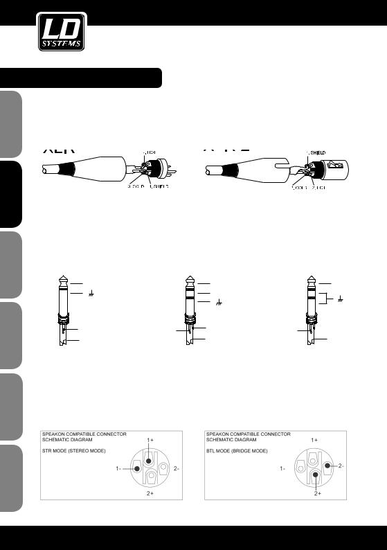
CONNECTOR PIN ASSIGNMENTS:
XLR-TYPE CONNECTOR PIN ASSIGNMENTS
XLR (male) |
XLR (female) |
|
|
|
|
|
|
|
|
|
|
|
|
|
TRS CONNECTOR PIN ASSIGNMENTS |
|
|
UNBALANCED |
BALANCED |
UNBALANCED |
+ |
|
+ |
|
+ |
|
|
- |
|
|
Tip |
Ring |
Tip |
Ring |
Tip |
Sleeve |
|
Sleeve |
|
Sleeve |
POLSKI
ITALIANO
SPEAKON-COMPATIBLE CONNECTOR PIN ASSIGNMENTS
STR POSITION (STEREO MODE) BTL POSITION (BRIDGE MODE)
10
WIRING EXAMPLE:
DEUTSCH ENGLISH
FRANCAIS |
ESPAÑOL
ITALIANO POLSKI
11

ESPAÑOL FRANCAIS DEUTSCH ENGLISH
POLSKI
ITALIANO
SPECIFICATIONS:
|
|
LDDJ300 |
|
LDDJ500 |
LDDJ800 |
Product type: |
|
|
|
Power amplifier |
|
Type: |
|
|
|
2-channel |
|
Output power (1 kHz @ 4 |
W |
2 x 150 |
|
2 x 250 |
2 x 400 |
ohms): |
|
|
|
|
|
Output power (1 kHz @ 8 |
W |
2 x 100 |
|
2 x 150 |
2 x 240 |
ohms): |
|
|
|
|
|
Output power (1 kHz @ 8 |
W |
250 |
|
500 |
800 |
ohms, bridged mode): |
|
|
|
|
|
Circuit concept: |
|
|
|
Class A/B |
|
Frequency response: |
Hz |
|
20 - 20.000 |
|
|
THD: |
|
0,03% |
|
0,04% |
0,04% |
S/N ratio: |
dB |
74 |
|
88 |
98 |
Crosstalk: |
dB |
70 |
|
71 |
72 |
Voltage gain: |
dB |
28 |
|
30 |
32 |
Input sensitivity: |
V |
1 |
|
1 |
1 |
Input impedance: |
kOhms |
32 |
|
32 |
32 |
Protection: |
|
|
DC, overheating, short-circuit, overcurrent, |
||
|
|
|
|
power-on delay |
|
Controls: |
|
Power switch, Channel A volume, Channel B volume, ground lift, |
|||
|
|
|
|
bridge / stereo mode |
|
Indicators: |
|
|
Power, Clip A, Clip B, Protect |
||
Line in- / outputs: |
|
|
2 x XLR, 2 x 6.3 mm jack |
|
|
Speaker outputs: |
|
|
2 x Speakon-compatible, 2 x terminal posts |
||
Cooling system: |
|
|
|
low-noise fan |
|
Power supply: |
|
|
|
transformer |
|
Operating voltage: |
V |
|
|
220 - 240 V AC, 50 Hz |
|
Power consumption (at |
W |
430 |
|
690 |
1100 |
full load): |
|
|
|
|
|
Dimensions (W x H x D): |
mm |
|
|
482 x 88 x 298 |
|
Weight: |
kg |
8,5 |
|
9 |
10,1 |
Accessories included in |
|
|
power cable, user manual |
|
|
package: |
|
|
|
|
|
12

MANUFACTURER´S DECLARATIONS:
LIMITED WARRANTY
This Limited Warranty applies to the Adam Hall, LD Systems, Defender, Palmer, Cameo and Eminence branded products.
The statutory warranty rights towards the seller are not affected by this guarantee. In fact, it justifies, additional independent warranty claims towards Adam Hall.
Adam Hall warrants that the Adam Hall product you have purchased from Adam Hall or from an Adam Hall authorized reseller is free from defects in materials or workmanship under normal use for a period of 2 or 3 years from the date of purchase.
The Limited Warranty Period starts on the date of purchase. In order to receive warranty services you are required to provide proof of the purchase date. Your dated sales or delivery receipt, showing the date of purchase, is your proof of the purchase date. Should products of the brands named above be in need of repair within the
limited warranty period, you are entitled to warranty services according to the terms and conditions stated in this document.
This Limited Warranty extends only to the original purchaser of this Adam Hall branded product and is not transferable to anyone who obtains ownership of the Adam Hall branded product from the original purchaser. During the Limited Warranty Period, Adam Hall will repair or replace the defective component parts or the product. All component parts or hardware products removed under this Limited Warranty become the property of Adam Hall.
In the unlikely event that your Adam Hall product has a recurring failure, Adam Hall, at its discretion, may elect to provide you with a replacement unit of Adam Hall´s choice that is at least equivalent to your Adam Hall branded product in hardware performance.
Adam Hall does not warrant that the operation of this product will be uninterrupted or error-free. Adam Hall is not responsible for damage that occurs as a result of your failure to follow the instructions included with the Adam Hall branded product.
This Limited Warranty does not apply,
-to wear parts (e.g. accumulator)
-to any product from which the serial number has been removed or that has been damaged or rendered defective as the result of an accident
-in case of, misuse, abuse, or other external causes
-by operation outside the usage parameters stated in the user´s documentation shipped with the product by use of spare parts not manufactured or sold by Adam Hall
-by modification or service by anyone other than Adam Hall
These terms and conditions constitute the complete and exclusive warranty agreement between you and Adam Hall regarding the Adam Hall branded product you have purchased.
ESPAÑOL FRANCAIS DEUTSCH ENGLISH
ITALIANO POLSKI
13

ESPAÑOL FRANCAIS DEUTSCH ENGLISH
POLSKI
ITALIANO
MANUFACTURER´S DECLARATIONS:
LIMITATION OF LIABILITY
If your Adam Hall branded hardware product fails to work as warranted above, your sole and exclusive remedy shall be repair or replacement. Adam Halls’ maximum liability under this limited warranty is expressly limited to the lesser of the price you have paid for the product or the cost of repair or replacement of any hardware components that malfunction in conditions of normal use.
Adam Hall is not liable for any damages caused by the product or the failure of the product, including any lost profits or savings or special, incidental, or consequential damages. Adam Hall is not liable for any claim made by a third party or made by you for a third party.
This limitation of liability applies whether damages are sought, or claims are made, under this Limited Warranty or as a tort claim (including negligence and strict product liability), a contract claim, or any other claim. This limitation of liability cannot be waived or amended by any person. This limitation of liability will be effective even if you have advised Adam Hall of an authorized representative of Adam Hall of the possibility of any such damages. This limitation of liability however, will not apply to claims for personal injury.
This Limited Warranty gives you specific legal rights. You may also have other rights that may vary from state to state or from country to country. You are advised to consult applicable state or country laws for a full determination of your rights.
REQUESTING WARRANTY-SERVICE
To request warranty service for the product, contact Adam Hall or the Adam Hall authorized reseller from which you purchased the product.
EC DECLARATION OF CONFORMITY
These devices meet the essential requirements and further relevant specifications of Directives 2004/108/EC (EMC) and 2006/95/EC (LVD). For more information, see www.adamhall.com.
CORRECT DISPOSAL OF THIS PRODUCT (ELECTRICAL WASTE) 
(Applicable in the European Union and other European countries with separate collection systems)
This marking shown on the product or its literature, indicates that it should not be disposed with other household wastes at the end of its working life. To prevent possible harm to the environment or human health from uncontrolled waste disposal, please separate this from other types of wastes and recycle it responsibly to promote the sustainable reuse of material resources.
Household users should contact either the retailer where they purchased this product, or their local government office, for details on where and how they can recycle this item in an enviromentally friendly manner.
Business users should contact their supplier and check the terms and conditions of the purchase contract. This product should not be mixed with other commercial wastes for disposal.
14

MANUFACTURER´S DECLARATIONS:
WEEE-DECLARATION 
Your LD-Systems product was developed and manufactured with high quality materials and components wich can be recycled and/or reused. This symbol indicates that electrical and electronic equipment must be disposed of separately from normal waste at the end of its operational lifetime.
Please dispose of this product by bringing it to your local collection point or recycling centre for such equipment. This will help to protect the environment in which we all live.
BATTERIES AND ACCUMULATORS 
The supplied batteries or rechargeable batteries can be recycled. Please dispose of them as special waste or return them to your specialist dealer. In order to protect the environment, only dispose exhausted batteries.
ECOLOGY AND ENERGY SAVING
Saving electric energy helps to protect the environment. Please turn off all electrical equipment when it is not in use. To avoid power consuption in idle mode, disconnect all electrical equipment from mains when not in use.
Adam Hall GmbH, all rights reserved. The technical data and the functional product characteristics can be subject to modifications. The photocopying, the translation, and all other forms of copying of fragments or of the integrality of this user’s manual is prohibited.
ESPAÑOL FRANCAIS DEUTSCH ENGLISH
ITALIANO POLSKI
15

ESPAÑOL FRANCAIS DEUTSCH ENGLISH
POLSKI
ITALIANO
Sie haben die richtige Wahl getroffen!
Diese LD Systems Produkte werden Sie lange Jahre durch Zuverlässigkeit, Wirtschaftlichkeit und einfaches Handling überzeugen. Dafür garantiert LD Systems mit seinem Namen und seiner in vielen Jahren erworbenen Kompetenz als Hersteller hochwertiger Geräte.
Nehmen Sie sich nun ein paar Minuten Zeit, diese Anleitung zu lesen. Wir möchten, dass Sie einfach und schnell in den Genuss dieser Technik kommen.
Mehr Informationen zu LD SYSTEMS finden Sie auf unserer Internetseite WWW.LD-SYSTEMS.COM
Einführung
Mit den von Grund auf neu konzipierten Modellen der DJ-Serie stellt LD Systems drei schnörkellose Endstufen vor, die mit zuverlässigem Betrieb, solider Konstruktion und einem hervorragenden Preis-Leistungs-Verhältnis absolut überzeugen. Die kompakten Leichtgewichte im 2HE Rackformat warten mit Leistungen von 150W bis 400W an 4 Ohm pro Kanal auf und lassen sich flexibel in allen mobilen Anwendungen und Festinstallationen einsetzen. Sie sind damit nicht nur für DJs eine ausgezeichnete Wahl.
Die Modellvarianten DJ300, DJ500 und DJ800 im bewährten Class AB-Design besitzen einen Übertragungsbereich von 20Hz – 20kHz mit hoher Dynamik und Impulstreue. Sie sind rundum professionell ausgestattet: die Eingänge sind als XLRund Stereo-Klinkenbuchsen ausgeführt, die sowohl symmetrisch als auch unsymmetrisch belegt werden können. Zum Anschluß der Lautsprecher dienen Speakon-kompatible Ausgänge und kräftige Schraubklemmen, die auch Bananenstecker aufnehmen.
Die LD Systems DJ-Endstufen sind gegen Kurzschluß, Gleichstrom, Überhitzung und Überlast geschützt und verfügen über eine Einschaltverzögerung. Ein geräuscharmer Lüfter sorgt für Kühlung. Neben den griffigen Pegelstellern zeigen LEDs auf der Front die Netzversorgung, Übersteuern und Ansprechen der Schutzschaltung in unterschiedlichen Farben deutlich an. Die Netzsicherung ist in die IEC-Buchse integriert, versenkt montierte Schalter für Brückenbetrieb und Ground Lift zur Beseitigung von Erdschleifen runden die Ausstattung der DJSerie ab.
16

LD DJ SERIE
PA ENDSTUFE
LDDJ300 / LDDJ500 / LDDJ800
ESPAÑOL FRANCAIS DEUTSCH ENGLISH
ITALIANO POLSKI
17

SICHERHEITSHINWEISE:
ESPAÑOL FRANCAIS DEUTSCH ENGLISH
POLSKI
ITALIANO
1.Lesen Sie diese Anleitung bitte sorgfältig durch.
2.Bewahren Sie alle Informationen und Anleitungen an einem sicheren Ort auf.
3.Befolgen Sie die Anweisungen.
4.Beachten Sie alle Warnhinweise. Entfernen Sie keine Sicherheitshinweise oder andere Informationen vom Gerät.
5.Verwenden Sie das Gerät nur in der vorgesehenen Art und Weise.
6.Verwenden Sie ausschließlich stabile und passende Stative bzw. Befestigungen (bei Festinstallationen). Stellen Sie sicher, dass Wandhalterungen ordnungsgemäß installiert und gesichert sind. Stellen Sie sicher, dass das Gerät sicher installiert ist und nicht herunterfallen kann.
7.Beachten Sie bei der Installation die für Ihr Land geltenden Sicherheitsvorschriften.
8.Installieren und betreiben Sie das Gerät nicht in der Nähe von Heizkörpern, Wärmespeichern, Öfen oder sonstigen Wärmequellen. Sorgen Sie dafür, dass das Gerät immer so installiert ist, dass es ausreichend gekühlt wird und nicht überhitzen kann.
9.Platzieren Sie keine Zündquellen wie z.B. brennende Kerzen auf dem Gerät.
10.Lüftungsschlitze dürfen nicht blockiert werden.
11.Betreiben Sie das Gerät nicht in unmittelbarer Nähe von Wasser. Bringen Sie das Gerät nicht mit brennbaren Materialien, Flüssigkeiten oder Gasen in Berührung.
12.Sorgen Sie dafür, dass kein Tropfoder Spritzwasser in das Gerät eindringen kann. Stellen Sie keine mit Flüssigkeit gefüllten Behältnisse wie Vasen oder Trinkgefäße auf das Gerät.
13.Sorgen Sie dafür, dass keine Gegenstände in das Gerät fallen können.
14.Betreiben Sie das Gerät nur mit dem vom Hersteller empfohlenen und vorgesehenen Zubehör.
15.ACHTUNG: Wenn das Netzkabel des Geräts mit einem Schutzkontakt ausgestattet ist, muss es an einer Steckdose mit Schutzleiter angeschlossen werden. Deaktivieren Sie niemals den Schutzleiter eines Netzkabels.
16.Schalten Sie das Gerät nicht sofort ein, wenn es starken Temperaturschwankungen ausgesetzt war (beispielsweise nach dem Transport). Feuchtigkeit und Kondensat könnten das Gerät beschädigen. Schalten Sie das Gerät erst ein, wenn es Zimmertemperatur erreicht hat.
17.Öffnen Sie das Gerät nicht und verändern Sie es nicht.
18.Bevor Sie das Gerät an die Steckdose anschließen, prüfen Sie zuerst, ob die Spannung und die Frequenz des Stromnetzes mit den auf dem Gerät angegebenen Werten übereinstimmen. Verfügt das Gerät über einen Spannungswahlschalter, schließen Sie das Gerät nur an die Steckdose an, wenn die Gerätewerte mit den Werten des Stromnetzes übereinstimmen.
Wenn das mitgelieferte Netzkabel bzw. der mitgelieferte Netzadapter nicht in Ihre Netzsteckdose passt, wenden Sie sich an Ihren Elektriker.
19.Treten Sie nicht auf das Netzkabel. Sorgen Sie dafür, dass spannungsführende Kabel speziell an der Netzbuchse bzw. am Netzadapter und der Gerätebuchse nicht geknickt werden.
20.Überprüfen Sie nach dem Anschluss des Geräts alle Kabelwege, um Schäden oder Unfälle, z. B. durch Stolperfallen zu vermeiden.
21.Achten Sie bei der Verkabelung des Geräts immer darauf, dass das Netzkabel bzw. der Netzadapter stets frei zugänglich ist. Trennen Sie das Gerät stets von der Stromzuführung, wenn das Gerät nicht benutzt wird, oder Sie das Gerät reinigen möchten.
Ziehen Sie Netzkabel und Netzadapter immer am Stecker bzw. am Adapter und nicht am Kabel aus der Steckdose. Berühren Sie Netzkabel und Netzadapter niemals mit nassen Händen.
22.Schalten Sie das Gerät möglichst nicht schnell hintereinander ein und aus, da sonst die Lebensdauer des Geräts beeinträchtigt werden könnte.
18

SICHERHEITSHINWEISE:
23. WICHTIGER HINWEIS: Ersetzen Sie Sicherungen ausschließlich durch Sicherungen des gleichen Typs
und Werten. Sollte eine Sicherung wiederholt auslösen, wenden Sie sich bitte an ein autorisiertes Servicezentrum.
24.Um das Gerät vollständig vom Stromnetz zu trennen, entfernen Sie das Netzkabel bzw. den Netzadapter aus der Steckdose.
25.Wenn Ihr Gerät mit einem Volex-Netzanschluss bestückt ist, muss der passende Volex-Gerätestecker entsperrt werden, bevor er entfernt werden kann. Das bedeutet aber auch, dass das Gerät durch eine Ziehen
am Netzkabel verrutschen und herunterfallen kann, wodurch Personen verletzt werden und/oder andere Schäden auftreten können. Verlegen Sie Ihre Kabel daher immer sorgfältig.
26.Entfernen Sie Netzkabel und Netzadapter aus der Steckdose bei Gefahr eines Blitzschlags oder wenn Sie das Gerät länger nicht verwenden.
27.Achten Sie beim Transport darauf, dass das Gerät nicht herunterfallen und dabei möglicherweise Sachund Personenschäden verursachen kann.
28.Wenn Ihr Gerät nicht mehr ordnungsgemäß funktioniert, Flüssigkeiten oder Gegenstände in das Geräteinnere gelangt sind, oder das Gerät anderweitig beschädigt wurde, schalten Sie es sofort aus und trennen es von der Netzsteckdose. Dieses Gerät darf nur von autorisiertem Fachpersonal repariert werden.
29.Verwenden Sie zur Reinigung des Geräts ein trockenes Tuch.
30.Beachten Sie alle in Ihrem Land geltenden Entsorgungsgesetze. Trennen Sie bei der Entsorgung bitte Kunststoff und Papier bzw. Kartonagen voneinander.
31.Kunststoffbeutel müssen außer Reichweite von Kindern aufbewahrt werden.
|
CAUTION |
ACHTUNG: |
RISK OF ELECTRIC SHOCK |
DO NOT OPEN |
Entfernen Sie niemals die Abdeckung, da sonst das Risiko eines elektrischen Schlages besteht. Im Inneren des Geräts befinden sich keine Teile, die vom Bediener repariert oder gewartet werden können. Lassen Sie Reparaturen ausschließlich von qualifiziertem Service-Personal durchführen.
Das gleichschenkelige Dreieck mit dem Blitzsymbol kennzeichnet nicht-isolierte, „gefährliche“ Spannungen im Gerät,
die einen für die Gesundheit gefährlichen Stromschlag verursachen können.
Das gleichschenkelige Dreieck mit dem Ausrufezeichen kennzeichnet wichtige Bedienungsund Wartungshinweise
ACHTUNG! HOHE LAUTSTÄRKEN!
Dieses Gerät ist für den professionellen Einsatz vorgesehen. Der kommerzielle Betrieb dieses Geräts unterliegt den jeweils gültigen nationalen Vorschriften und Richtlinien zur Unfallverhütung. Als Hersteller ist Adam Hall gesetzlich verpflichtet, Sie ausdrücklich auf mögliche Gesundheitsrisiken hinzuweisen.
Gehörschäden durch hohe Lautstärken und Dauerbelastung: Bei der Verwendung dieses Produkts können hohe Schalldruckpegel (SPL) erzeugt werden, die bei Künstlern, Mitarbeitern und Zuschauern zu irreparablen Gehörschäden führen können. Vermeiden Sie länger anhaltende Belastung durch hohe Lautstärken über 90 dB.
ESPAÑOL FRANCAIS DEUTSCH ENGLISH
ITALIANO POLSKI
19

ESPAÑOL FRANCAIS DEUTSCH ENGLISH
POLSKI
ITALIANO
SICHERHEITSHINWEISE:
GEFAHREN AM LAUTSPRECHERAUSGANG!
Endstufen sind in der Lage, gefährlich hohe Spannungen am Ausgang zu produzieren. Zur Vermeidung eines Stromschlags berühren Sie keinesfalls blanke Lautsprecherleitungen, oder Polklemmen während des Betriebs der Endstufe.
INSTALLATION UND VERKABELUNG
Für einen störungsfreien Betrieb ist bei Aufstellung und Rackeinbau unbedingt darauf zu achten, dass die Luftzufuhr und die Entlüftung der Endstufe nicht behindert wird (Lüftungsschlitze auf der Vorderseite, Lüfter auf der Rückseite).
Wir empfehlen den Einsatz hochwertiger, symmetrischer NF-Kabel (mit zwei Leitern für das Audiosignal plus separater Abschirmung) mit XLR-Steckverbindern um die Signalquelle (z.B. Mischpult) mit der Endstufe zu verbinden. Es ist zwar auch möglich, unsymmetrische Kabel an den Endstufeneingängen anzuschließen, aus Gründen der Störfestigkeit sollte jedoch der Verwendung symmetrischer Kabel grundsätzlich der Vorzug gegeben werden.
Um Leistungsverluste zu minimieren, sind für die Verkabelung von Lautsprechern twinaxiale Lautsprecherkabel mit ausreichend großem Querschnitt zu verwenden.
20
FRONT / BEDIENELEMENTE:
4 |
5 |
4 |
|
3 |
|
1 |
2 |
2 |
1NETZSCHALTER
Vor dem Einund Ausschalten stets die Lautstärke beider Kanäle auf Null drehen (Regler auf Linksanschlag).
2LAUTSTÄRKEREGLER KANAL A UND B
Nach rechts gedreht erhöht sich, nach links gedreht verringert sich die Lautstärke.
In der Bridge Betriebsart (BTL) wird die Lautstärke der Endstufe von Lautstärkeregler Kanal A kontrolliert.
3POWER LED
Leuchtet auf, wenn die Endstufe eingeschaltet und korrekt am Stromnetz angeschlossen ist.
4CLIP LED KANAL A UND B
Leuchtet auf, sobald die Endstufe im Grenzbereich betrieben wird. Das sollte durch Absenken des Eingangspegels vermieden werden, da sonst Verzerrungen entstehen, die zum einen das Klangergebnis negativ beeinflussen und zum anderen Schäden an angeschlossenen Lautsprechern verursachen können.
5PROTECT LED
Leuchtet nach dem Einschalten auf, solange die Einschaltverzögerung aktiv ist. Nach dem Erlöschen der Protect LED ist die Endstufe betriebsbereit.
Die Protect LED leuchtet auf, wenn eine der Schutzschaltungen in der Endstufe aktiv ist. Um die Leistungsverstärker und angeschlossene Lautsprecher zu schützen, werden im Protect Modus die Lautsprecherausgänge abgeschaltet. Wird die Fehlerquelle beseitigt (z.B. Überlast, oder Kurzschluss am Lautsprecherausgang), kehrt die Endstufe nach kurzer Zeit in den Normalzustand zurück, die Protect LED erlischt und die Lautsprecherausgänge werden wieder eingeschaltet.
Erlischt die Protect LED nach kurzer Zeit selbst dann nicht, wenn sowohl eingangsals auch ausgangsseitig alle Verbindungen getrennt wurden, liegt ein interner Fehler vor. Die Endstufe ist in diesem Fall auszuschalten, vom Netz zu nehmen und einem autorisierten Servicezentrum zu übergeben.
ESPAÑOL FRANCAIS DEUTSCH ENGLISH
ITALIANO POLSKI
21

ESPAÑOL FRANCAIS DEUTSCH ENGLISH
POLSKI
ITALIANO
RÜCKSEITE / ANSCHLÜSSE & BEDIENELEMENTE:
ABGEBILDET: LDDJ300
4 
 4
4
1
7 |
6 |
2 |
3 |
3 |
2 |
5 |
5 |
1NETZBUCHSE MIT SICHERUNGSHALTER
Vergewissern Sie sich stets, dass die Betriebsspannung der Endstufe (Aufdruck auf der Rückseite der Endstufe) der in Ihrer Region geltenden Netzspannung entspricht. Ein geeignetes Netzkabel ist im Lieferumfang enthalten.
Trennen Sie die Endstufe während der Installation immer von der Netzversorgung.
WICHTIGER HINWEIS: Ersetzen Sie die Sicherung ausschließlich durch eine Sicherung des gleichen Typs und mit gleichen Werten (Aufdruck auf der Rückseite der Endstufe). Sollte die Sicherung wiederholt durchbrennen, wenden Sie sich bitte an ein autorisiertes Servicezentrum.
2SYMMETRISCHER XLR-EINGANG KANAL A UND B
Die XLR Eingangsbuchsen dienen der Verbindung mit einem Mischpult oder einer anderen Signalquelle. Im Bridge Modus BTL (Bridge Tied Load) muss Kanal A als Eingang verwendet werden.
3SYMMETRISCHER KLINKENEINGANG / LINK AUSGANG
Diese 6,3 mm Klinkenbuchsen können wahlweise als Audioeingang, oder zum Weiterschleifen der an den XLR Eingangsbuchsen anliegenden Signale genutzt werden. Es können auch unsymmetrische Klinkenkabel verwendet werden, wobei zu beachten ist, dass beim Weiterschleifen des Signals mit unsymmetrischen Klinkenkabeln die Ansteuerung der Endstufe automatisch unsymmetrisch wird.
4SPEAKON KOMPATIBLE LAUTSPRECHERAUSGÄNGE KANAL A UND B
Anschluss von Lautsprechern bzw. Lautsprechersystemen von mindestens 4 Ohm Gesamtimpedanz pro Kanal. Im Bridge Modus BTL (Bridge Tied Load) muss Ausgangsbuchse Kanal A verwendet werden, wobei darauf zu achten ist, dass Pin 2+ und 2- der Speakon kompatiblen Buchse belegt sind.
WICHTIG: Im Bridge Modus darf die Gesamtimpedanz des angeschlossenen Lautsprechersystems 8 Ohm nicht unterschreiten.
22
RÜCKSEITE / ANSCHLÜSSE & BEDIENELEMENTE:
5LAUTSPRECHERKLEMMANSCHLUSS KANAL A UND B
Anschluss von Lautsprechern bzw. Lautsprechersystemen von mindestens 4 Ohm Gesamtimpedanz pro Kanal. Verbinden Sie den Pluspol (+) des Lautsprecherkabels mit dem roten Klemmanschluss (+) und den Minuspol (-) des Lautsprecherkabels mit dem schwarzen Klemmanschluss (-) des jeweiligen Kanals. Wahlweise können auch Lautsprecherkabel mit Bananensteckern verwendet werden.
Im Bridge Modus BTL (Bridge Tied Load) müssen roter Klemmanschluss Kanal A als Pluspol (+) und roter Klemmanschluss Kanal B als Minuspol (-) verwendet werden.
WICHTIG: Im Bridge Modus darf die Gesamtimpedanz des angeschlossenen Lautsprechersystems 8 Ohm nicht unterschreiten.
6GROUND-LIFT SCHALTER
Dient zur Vermeidung von Brummschleifen. In LIFT-Stellung ist die Verbindung der Gehäuseund der Signalmasse getrennt.
7MODE SCHALTER
In STR-Stellung (Stereo Modus) arbeiten Endstufen A und B unabhängig voneinander. Es können sowohl StereoSignale als auch völlig unterschiedliche Signale über Kanal A und B verstärkt werden.
In BTL-Stellung (Bridge Modus) werden Enstufen A und B zu einer leistungsstärkeren Mono-Endstufe verschaltet. WICHTIG: Im Bridge Modus darf die Gesamtimpedanz des angeschlossenen Lautsprechersystems 8 Ohm nicht unterschreiten.
ESPAÑOL FRANCAIS DEUTSCH ENGLISH
ITALIANO POLSKI
23
ESPAÑOL FRANCAIS DEUTSCH ENGLISH
STECKERBELEGUNG:
BELEGUNG XLR-STECKER
XLR (male) |
XLR (female) |
|
|
|
|
|
|
|
|
|
|
|
|
|
BELEGUNG KLINKENSTECKER |
|
|
UNSYMMETRISCH |
SYMMETRISCH |
UNSYMMETRISCH |
+ |
|
+ |
|
+ |
|
|
- |
|
|
Tip |
Ring |
Tip |
Ring |
Tip |
Sleeve |
|
Sleeve |
|
Sleeve |
POLSKI
ITALIANO
BELEGUNG SPEAKON KOMPATIBLE ANSCHLÜSSE
STR STELLUNG (STEREO MODUS) |
BTL STELLUNG (BRIDGE MODUS) |
24

VERKABELUNGSBEISPIEL:
DEUTSCH ENGLISH
FRANCAIS |
ESPAÑOL
ITALIANO POLSKI
25

ESPAÑOL FRANCAIS DEUTSCH ENGLISH
POLSKI
ITALIANO
SPEZIFIKATIONEN:
|
|
LDDJ300 |
|
LDDJ500 |
LDDJ800 |
Produktart: |
|
|
|
Endstufe |
|
Typ: |
|
|
|
2-Kanal |
|
Ausgangsleistung (1 kHz |
W |
2 x 150 |
|
2 x 250 |
2 x 400 |
@ 4 Ohm): |
|
|
|
|
|
Ausgangsleistung (1 kHz |
W |
2 x 100 |
|
2 x 150 |
2 x 240 |
@ 8 Ohm): |
|
|
|
|
|
Ausgangsleistung (1 kHz |
W |
250 |
|
500 |
800 |
@ 8 Ohm, Bridge-Modus): |
|
|
|
|
|
Schaltungskonzept: |
|
|
|
Class A/B |
|
Frequenzgang: |
Hz |
|
20 - 20.000 |
|
|
Klirrfaktor (THD): |
|
0,03% |
|
0,04% |
0,04% |
Geräuschspannungsab- |
dB |
74 |
|
88 |
98 |
stand: |
|
|
|
|
|
Übersprechen: |
dB |
70 |
|
71 |
72 |
Spannungsverstärkung |
dB |
28 |
|
30 |
32 |
(Gain): |
|
|
|
|
|
Eingangsempfindlichkeit: |
V |
1 |
|
1 |
1 |
Eingangsimpedanz: |
kOhm |
32 |
|
32 |
32 |
Schutzschaltungen: |
|
|
Gleichspannung, Überhitzung, Kurzschluss, Überstrom, |
||
|
|
|
|
Einschaltverzögerung |
|
Bedienelemente: |
|
Netzschalter, Lautstärke Kanal A, Lautstärke Kanal B, Ground lift, |
|||
|
|
|
|
Bridge- / Stereo Modus |
|
Anzeigeelemente: |
|
|
Power, Clip A, Clip B, Protect |
||
Line-Ein- / Ausgänge: |
|
|
2 x XLR, 2 x 6,3 mm Klinke |
||
Lautsprecherausgänge: |
|
|
2 x Speakon kompatibel, 2 x Polklemmen |
||
Kühlung: |
|
|
|
geräuscharmer Lüfter |
|
Stromversorgung: |
|
|
|
Transformator |
|
Betriebsspannung: |
V |
|
|
220 - 240 V AC, 50 Hz |
|
Leistungsaufnahme (bei |
W |
430 |
|
690 |
1100 |
Volllast): |
|
|
|
|
|
Abmessungen (B x H x T): |
mm |
|
|
482 x 88 x 298 |
|
Gewicht: |
kg |
8,5 |
|
9 |
10,1 |
Zubehör im Lieferumfang: |
|
|
Netzkabel, Bedienungsanleitung |
||
26
 Loading...