


USER´S MANUAL
BEDIENUNGSANLEITUNG
MANUEL D`UTILISATION
MANUAL DE USUARIO
INSTRUKCJA OBSŁUGI
MANUALE D‘ USO
LDMEI1000G²
WIRELESS IN EAR MONITORING SYSTEM

español FRANCAIS DEUTSCH ENGLISH
POLSKI
ITALIANO
You‘ve made the right choice!
We have designed this product to operate reliably over many years. LD Systems stands for this with its name and many years of experience as a manufacturer of high-quality audio products.
Please read this User‘s Manual carefully, so that you can begin making optimum use of your LD Systems product quickly.
You can find more information about LD SYSTEMS at our Internet site WWW.LD-SYSTEMS.COM
Introduction
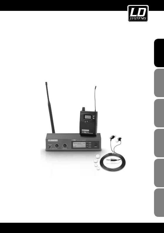
The new LD Systems MEI1000G2 is an In-Ear Monitoring-System with 96 UHF channels that delivers natural sound with a large dynamic range and outstanding crosstalk behaviour in the 823 – 832 and 863 – 865 MHz frequency bands.
Switchable mono, stereo, and focus monitoring modes as well as adjustable EQ and limiter functions permit natural sound reproduction for any application, with a frequency response of 60 Hz – 16 Hz, a high S/N ratio, and low THD. The LD MEI1000G2 allows for the simultaneous operation of up to 5 systems.
The earphones are very comfortable to wear, and the multifunctional display on the receiver shows all relevant system information. With high quality batteries, it is possible to attain operating times of 12 hours and more. The MEI100G2 package includes a 19" rackmount kit and a rugged carrying case made of ABS plastic.
2
LDMEI1000G²
WIRELESS IN EAR MONITORING SYSTEM
ESPAÑOL FRANCAIS DEUTSCH ENGLISH
ITALIANO POLSKI
3

español FRANCAIS DEUTSCH ENGLISH
POLSKI
ITALIANO
PREVENTIVE MEASURES:
1.Please read these instructions carefully.
2.Keep all information and instructions in a safe place.
3.Follow the instructions.
4.Observe all safety warnings. Never remove safety warnings or other information from the equipment.
5.Use the equipment only in the intended manner and for the intended purpose.
6.Use only sufficiently stable and compatible stands and/or mounts (for fixed installations). Make certain that wall mounts are properly installed and secured. Make certain that the equipment is installed securely and cannot fall down.
7.During installation, observ e the applicable safety regulations for your country.
8.Never install and operate the equipment near radiators, heat registers, ovens or other sources of heat. Make certain that the equipment is always installed so that is cooled sufficiently and cannot overheat.
9.Never place sources of ignition, e.g., burning candles, on the equipment.
10.Ventilation slits must not be blocked.
11.Do not use this equipment in the immediate vicinity of water (does not apply to special outdoor equipment - in this case, observe the special instructions noted below. Do not expose this equipment to flammable materials, fluids or gases.
12.Make certain that dripping or splashed water cannot enter the equipment. Do not place containers filled with liquids, such as vases or drinking vessels, on the equipment.
13.Make certain that objects cannot fall into the device.
14.Use this equipment only with the accessories recommended and intended by the manufacturer.
15.Do not open or modify this equipment.
16.After connecting the equipment, check all cables in order to prevent damage or accidents, e.g., due to tripping hazards.
17.During transport, make certain that the equipment cannot fall down and possibly cause property damage and personal injuries.
18.If your equipment is no longer functioning properly, if fluids or objects have gotten inside the equipment or
if it has been damaged in anot her way, switch it off immediately and unplug it from the mains outlet (if it is a powered device). This equipment may only be repaired by authorized, qualified personnel.
19.Clean the equipment using a dry cloth.
20.Comply with all applicable disposal laws in your country. During disposal of packaging, please separate plastic and paper/cardboard.
21.Plastic bags must be kept out of reach of children.
For equipment that connects to the power mains:
22.CAUTION: If the power cord of the device is equipped with an earthing contact, then it must be connected to an outlet with a protective ground. Never deactivate the protective ground of a power cord.
23.If the equipment has been exposed to strong fluctuations in temperature (for example, after transport), do not switch it on immediately. Moisture and condensation could damage the equipment. Do not switch on the equipment until it has reached room temperature.
24.Before connecting the equipment to the power outlet, first verify that the mains voltage and frequency match the values specified on the equipment. If the equipment has a voltage selection switch, connect the equipment to the power outlet only if the equipment values and the mains power values match. If the included power cord or power adapter does not fit in your wall outlet, contact your electrician.
25.Do not step on the power cord. Make certain that the power cable does not become kinked, especially at the mains outlet and/or power adapter and the equipment connector.
26.When connecting the equipment, make certain that the power cord or power adapter is always freely accessible. Always disconnect the equipment from the power supply if the equipment is not in use or if you want
4
SAFETY:
to clean the equipment. Always unplug the power cord and power adapter from the power outlet at the plug or adapter and not by pulling on the cord. Never touch the power cord and power adapter with wet hands.
27.Whenever possible, avoid switching the equipment on and off in quick succession because otherwise this can shorten the useful life of the equipment.
28.IMPORTANT INFORMATION: Replace fuses only with fuses of the same type and rating. If a fuse blows repeatedly, please contact an authorised service centre.
29.To disconnect the equipment from the power mains completely, unplug the power cord or power adapter from the power outlet.
30.If your device is equipped with a Volex power connector, the mating Volex equipment connector must be unlocked before it can be removed. However, this also means that the equipment can slide and fall down if the power cable is pulled, which can lead to personal injuries and/or other damage. For this reason, always be careful when laying cables.
31.Unplug the power cord and power adapter from the power outlet if there is a risk of a lightning strike or before extended periods of disuse.
CAUTION |
RISK OF ELECTRIC SHOCK |
DO NOT OPEN |
CAUTION:
Never remove the cover, because otherwise there may be a risk of electric shock. There are no user serviceable parts inside. Have repairs carried out only by qualified service personnel.
The lightning flash with arrowhead symbol within an equilateral triangle is intended to alert the user to the presence of uninsulated “dangerous voltage” within the product’s enclosure that may be of sufficient magnitude to constitute a risk of electrical shock.
The exclamation mark within an equilateral triangle is intended to alert the user to the presence of important operating and maintenance instructions.
CAUTION – HIGH VOLUME LEVELS WITH AUDIO PRODUCTS!
This equipment is intended for professional use. Therefore, commercial use of this equipment is subject to the respectively applicable national accident prevention rules and regulations. As a manufacturer, Adam Hall is obligated to notify you formally about the existence of potential health risks.
Hearing damage due to high volume and prolonged exposure: When in use, this product is capable of producing high sound-pressure levels (SPL) that can lead to irreversible hearing damage in performers, employees, and audience members. For this reason, avoid prolonged exposure to volumes in excess of 90 dB.
CAUTION! IMPORTANT INFORMATION ABOUT LIGHTING PRODUCTS
1.Do not look into the beam from a distance of less than 40 cm.
2.Do not stare into the beam for extended periods at short-to-medium distances.
3.Do not view the beam directly with optical instruments such as magnifiers.
4.Under some circumstances, stroboscopic effects may trigger epileptic seizures in sensitive individuals! For this reason, persons who suffer from epilepsy should always avoid places where strobe lights are used.
ESPAÑOL FRANCAIS DEUTSCH ENGLISH
ITALIANO POLSKI
5
español FRANCAIS DEUTSCH ENGLISH
POLSKI
ITALIANO
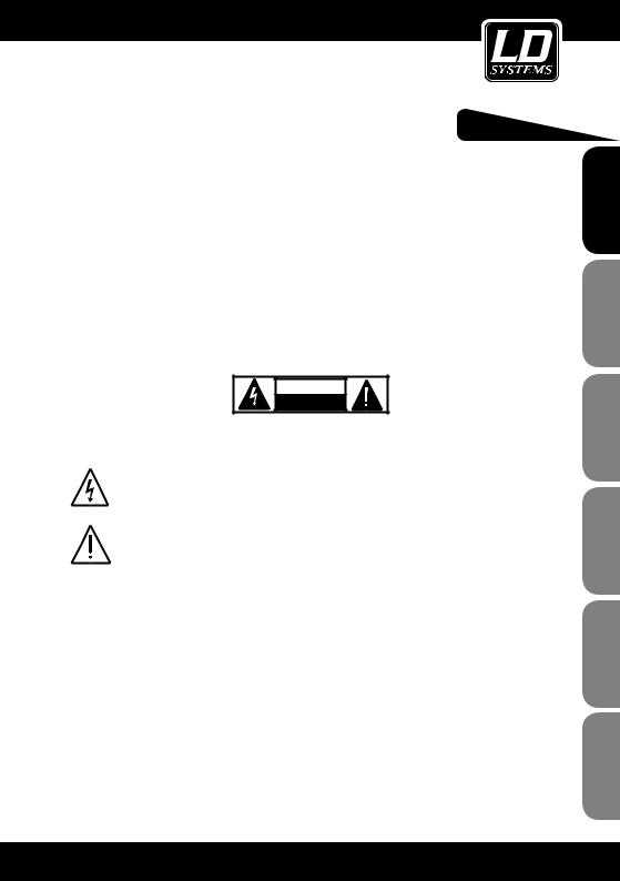
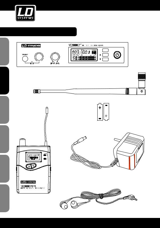
System components:
SET
POWER
Transmitter
Antenna
2 "AA" batteries
Power supply
Belt pack receiver
Earplugs
6

Connections, controls, and indicators:
Transmitter:
Front Panel
|
|
SET 4 |
1 |
|
|
3 |
|
8 |
7 |
6 |
|
|
2 |
POWER |
|
|
|
5 |
|
1POWER-BUTTON
Switch on: Press and hold button for two seconds. Switch off: Press and hold button for two seconds.
2ARROW DOWN BUTTON
See Chapter "System Setup".
3ARROW UP BUTTON
See Chapter "System Setup".
4SET (PROGRAMMING BUTTON)
See Chapter "System Setup".
5LC DISPLAY
Backlit LC Display. See Chapter "System Setup".
6INPUT LEVEL
Adjust the input sensitivity. In order to achieve an optimal signal to noise ratio, bring the input signal as close as possible to the 0dB indicator (level indicator AF L and AF R in the display), without exceeding the distortion limit (PEAK segment in the level meter).
7HEADPHONE VOLUME CONTROL
Turning the knob to the left decreases the volume; turning it to the right increases the volume. To avoid hearing damage, set the volume to minimum before using the earphones/headphones, then slowly increase the volume. Caution: high volume can cause permanent hearing damage.
8PHONES
Headphone output connector 6.3 mm stereo jack.
ESPAÑOL FRANCAIS DEUTSCH ENGLISH
ITALIANO POLSKI
7

español FRANCAIS DEUTSCH ENGLISH
POLSKI
ITALIANO
Connections, controls, and indicators:
Transmitter:
Rear panel
2 

 2
2

 4 1
4 1 


3
1 LOW VOLTAGE CONNECTOR
Power supply connector for 12 - 18V DC (included).
2BALANCED INPUT LEFT / RIGHT
Left and right-hand balanced inputs (XLR / 6.3 mm jack combo). In the mono mode, only the right input (RIGHT) may be used.
3PAD
Switchable level attenuation for high input level.
Switch in position -12 dB: Attenuation of the input signal by 12 db Switch in position 0 dB: No attenuation of the input signal.
4ANTENNA
TNC antenna connector 50 Ohm.
Belt pack receiver
BELT CLIP
Clip the receiver to your belt or a suitable strap. For optimum fit, the clip should always be pushed all the way over the belt and/or strap (see illustration).
Battery replacement
To replace the batteries, press gently on the marked spots on the sides of the battery cover and flip it forward. Remove the batteries, insert two new AA-batteries (for orientation please see the illustration in the battery compartment) and close the cover. Remove the batteries when the device is not in use for an extended period.
8

Connections, controls, and indicators:
Belt pack receiver:


 10
10
1ON/OFF - VOLUME
On / Off switch and volume control. To switch on, turn the knob to the right (clockwise) past the snap-in point. To switch off, turn the knob to the left (counter clockwise) past the snap-in point. Turning the knob to the left decreases the volume; turning it to the right increases the volume. To avoid hearing damage, set the volume to minimum before using the earphones/headphones, then slowly increase the volume. Caution: high volume can cause permanent hearing damage.
2PHONES
Earphone/headphone connector 3.5 mm stereo jack.
3ANTENNA
4 |
LC DISPLAY |
7 |
ARROW UP BUTTON |
|
Backlit LC Display. The back light automatically |
|
See Chapter "System Setup". |
|
turns off after about 30 seconds if no control |
|
|
|
buttons are pressed; the back light is turned on |
8 |
ARROW DOWN BUTTON |
|
when any of the control buttons is selected. See |
|
See Chapter "System Setup". |
|
Chapter "System Setup". |
|
|
5 |
LOW BATT LED |
9 |
ESC-BUTTON |
|
Press this button to return to the main menu. |
||
|
LED lights when the battery charge is low. Please |
|
|
|
replace the batteries as soon as possible. |
10 |
SET BUTTON |
6 |
RF SIGNAL LED |
|
See Chapter "System Setup". |
|
|
Lights up briefly when you switch on. Lights up when a HF signal is present. Radio frequency of both transmitter and receiver must match.
ESPAÑOL FRANCAIS DEUTSCH ENGLISH
ITALIANO POLSKI
9

español FRANCAIS DEUTSCH ENGLISH
POLSKI
ITALIANO
System setup:
1
2
3
4
5
TRANSMITTER PROGRAMMING:
1MAIN MENU
In the main menu the radio frequency, the operating mode (mono/ stereo) and signal level (AF L and AF R) are displayed.
2SELECTING A FREQUENCY GROUP 1 - 8
Press the SET button repeatedly until "GROUP SELECT" appears in the display. Press the keys to select the desired frequency group.
3SELECTING A CHANNEL 1 - 12
Press the SET button repeatedly until "CHANNEL SELECT" appears
in the display. Press the keys  to select the desired channel. Note: For simultaneous operation of several systems, please make sure that all the systems use different channels on the same frequency group.
4SELECTING THE OPERATING MODE
Press the SET button repeatedly until "MODE SELECT" appears in the display.
With the buttons, you can now choose between mono and stereo mode.
Select the mono mode if only one (mono)
audio signal is to be transmitted to the receiver. The signal is located on two channels (left/right) of the receiver. In the mono mode, only the right input (INPUT RIGHT) may be used.
Select the stereo mode if either a stereo signal, or two mono signals are to be transmitted to the receiver.
Please refer to the notes in the Stereo and Focus Mode chapter.
5LOCK AGAINST INADVERTENT CHANGES
Press the SET button repeatedly until "LOCK SELECT" appears in
the display. Press the keys  to lock or unlock the system. If "LOCK SELECT is enabled, the system settings can be viewed, but not changed.
EXIT THE SETUP MENU
Press the SET button repeatedly until "EXIT SETUP" appears in the display. Press the keys  to exit the menu. If no control buttons are pressed, the display switches automatically to the main menu after a few seconds.
10
1
2
3
4
5
System setup:
RECEIVER PROGRAMMING:
To change settings on the receiver, press gently on the marked spots on the sides of the battery cover and flip it forward. The Escape (ESC) and SET buttons are now accessible. To return to the main menu after a setting change, press the Escape button (ESC).
1MAIN MENU
In the main menu, the radio frequency, RF and AF level, mono / stereo mode, EQ, limiter, as well as the lock status are displayed.
2BALANCE
Adjust the volume balance between the left and right channels of
a stereo signal using the  buttons. When the transmitter is in mono mode, using the
  buttons will set the position of the signal in the panoramic field.
3SELECTING A FREQUENCY GROUP 1 - 8
Press the SET button repeatedly on the receiver until "GROUP"
appears and starts to flash. Press the keys  to select the desired frequency group.
4SELECTING A CHANNEL 1 - 12
Press the SET button until "CHANNEL" appears in the display and flashes, and then select .
. the desired channel using
5EQUALIZER
Press the SET button repeatedly until "EQ" appears in the display
and flashes. Use the buttons  to determine whether the Equalizer should be enabled (EQ ON), or disabled (EQ OFF). When the EQ is enabled, the treble at 10kHz is increased by around 6dB.
ESPAÑOL FRANCAIS DEUTSCH ENGLISH
ITALIANO POLSKI
11
español FRANCAIS DEUTSCH ENGLISH
POLSKI
ITALIANO
System setup:
6
7
8
6LIMITER
Press the SET button repeatedly until "LIMITER" appears in
the display and flashes. Using the  button, you can enable (Limiter ON) or disable (limiter OFF) the limiter.
7LOCKING THE RECEIVER
Press the SET button repeatedly until the lock symbol appears in
the display. Press the  button to lock (ON) or release (OFF) the receiver. If the receiver is locked, the settings can be viewed, but not changed.
8BATTERY CHARGE STATUS
The charge status of the batteries is shown in four stages. In addition to the fourth stage (no bars on the battery symbol) the red LOW BATT LED will light up next to the display. The batteries should now be replaced immediately.
12

1
2
System setup:
RECEIVER PROGRAMMING:
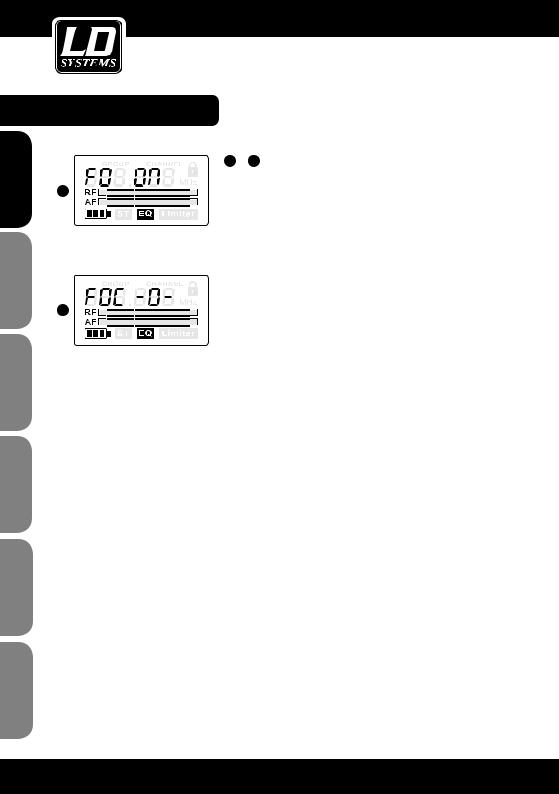
1 + 2 STEREO MODE
Select the stereo mode for the transmission of a stereophonic audio signal.
Press the SET button repeatedly until "FO OFF" or "FO ON" appears in the display and flashes. Using the  buttons, you can now activate the stereo mode (FO OFF).
In stereo mode, the two input signals of the transmitter can be heard through headphones (on the left and right) connected to the receiver
On the receiver, the balance between the two input signals
|
|
|
|
|
|
|
|
|
|
|
|
|
can be set with the help of the |
buttons. A total of 31 |
|
|
|
|
|
|
|
|
|
|
|
|
|
levels are available : using the |
button, the centre location |
|
|
|
|
|
|
|
|
|
|
|
|
|
of a stereo signal can be changed by 15 levels to the right
(1-, 2-, 3-, 4-, 5-, 6-, 7-, 8-, 9-, A-, b-, C-, d-, E-, F-)  and by 15 levels to the left (-1, -2, -3, -4, -5, -6, -7, -8, -9, -A, -b, -C, -d, -E, -F). To bring the centre location of a stereophonic audio signal to the centre of the stereo base, please select the -0- setting. To ensure the transmission of a stereo
audio signal in the stereo mode, both the transmitter and the receiver have to be in stereo mode and an audio signal has to be present at the INPUT LEFT and RIGHT entrances. When the transmitter is in mono mode, only the audio signal (INPUT RIGHT) is being transferred.
ESPAÑOL FRANCAIS DEUTSCH ENGLISH
ITALIANO POLSKI
13
español FRANCAIS DEUTSCH ENGLISH
POLSKI
ITALIANO
System setup:
3
4
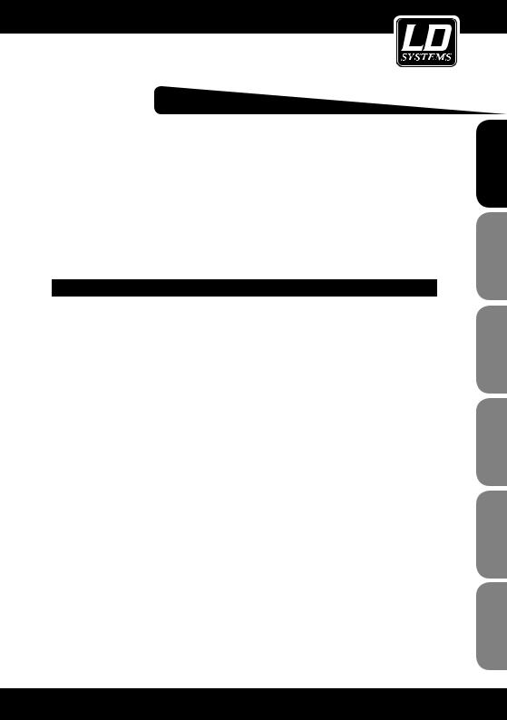
3 + 4 FOCUS MODE (ALSO KNOWN AS "DUAL MONO")
Select the Focus mode in order to listen to two mono signals in the centre of the panoramic field, and to customize their volume. Example Rock Band (user is the lead singer): the first mono audio signal comprises a mix of drums, bass and guitar (the mixer is fed by a monitor signal 1). The second mono audio signal contains the microphone signal of the singer (the mixer is fed by monitor signal 2). The singer can now directly adjust the volume balance between the instruments and his voice and the overall volume level.
Press the SET button repeatedly until "FO OFF" or "FO ON" appears in the display and flashes. Using the  buttons, you can now activate the Focus mode (FO ON).
In Focus mode the two input signals of the transmitter are mixed together and played back in mono. The user can now directly adjust the volume balance of the signals  by up to 31 levels with the help of the buttons on the receiver To push the mono signal of the transmitter (INPUT RIGHT) into the background, use the button
  (15 levels: FOC 1-, 2-, 3-, 4-, 5-, 6-, 7-, 8-, 9-, A-, b-, C-, d-, E-, max. F-). The volume balance is changed in favour of the audio signal at the left input (INPUT LEFT) of the transmitter.
To push the mono signal of the transmitter (INPUT LEFT) into the background, use the button  (15 levels: FOC -1, -2, -3, -4, -5, -6, -7, -8, -9, -A, -b, -C, -d, -E, a max. -F). The volume balance is changed in favour of the audio signal at the
right input (INPUT RIGHT) of the transmitter. In the FOC -0- setting, both input signals of the transmitter are transmitted at the same volume.
To ensure the transmission of a stereo audio signal in the Focus mode, both the transmitter and the receiver have to be in stereo mode and an audio signal must be present at both INPUT LEFT and RIGHT entrances. When the transmitter is in mono mode, only the (INPUT RIGHT) audio signal is being transmitted.
14
Setting up and troubleshooting:
SETUP
For optimal transmission, position the transmitter at a minimum height of 1 m and point the antenna upwards. If multiple wireless systems are used in an installation, please make sure
that the antennas do not touch or cross. Do not position the transmitter in the direct vicinity
of metal objects and digitally controlled devices (CD players, computers, digital consoles, etc.). Transmitter and receiver should be within direct "line of sight" of each other.
TROUBLESHOOTING
PROBLEM |
DISPLAY |
SOLUTION |
|
|
|
|
|
|
Receiver: Display is switched off. |
Make certain that the batteries are not dead |
|
|
and the receiver is on. |
||
|
|
||
|
|
|
|
|
Transmitter: Display is switched |
Check the connection between power supply |
|
|
off. |
and transmitter. Turn on the transmitter. |
|
|
|
Make certain that the transmitter and receiver |
|
|
|
are set to the same radio frequency. |
|
|
|
|
|
|
|
Reduce the distance between transmitter |
|
No sound or volume |
Receiver: is on, but the RF indica- |
and receiver and make certain that there |
|
too low. |
tor is not lit. |
is a direct line of sight between transmitter |
|
|
|
and receiver. |
|
|
|
|
|
|
|
Make certain that the transmitter antenna is |
|
|
|
installed correctly. |
|
|
|
Increase the volume at the receiver and |
|
|
Receiver: is on and the RF indica- |
check the headphone connection. |
|
|
tor is lit. |
Check the input level on the transmitter and |
|
|
|
increase it if necessary. |
|
|
|
Increase the distance to possible causes of |
|
Distortion or noise. |
Receiver: RF indicator is on. |
interference (digitally controlled devices, e.g., |
|
CD players, computers, digital consoles…). |
|||
|
|
||
|
|
Use a different radio frequency. |
|
|
Receiver: LOW BATT LED lights up |
Replace the batteries with new ones. |
|
Distorted sound. |
|
|
|
Transmitter: Level indicator is |
Lower the volume at the level controls of |
||
|
too high |
the transmitter or at the source device. |
ESPAÑOL FRANCAIS DEUTSCH ENGLISH
ITALIANO POLSKI
15

Troubleshooting:
español FRANCAIS DEUTSCH ENGLISH
POLSKI
ITALIANO
Stereo and Focus |
|
|
|
mode: Only the right |
|
|
|
input signal of the |
|
|
|
transmitter is heard, |
Transmitter: The transmitter is in |
Switch the transmitter to the stereo mode. |
|
although the receiver |
the mono mode. |
||
|
|||
is in the stereo mode |
|
|
|
and both inputs of the |
|
|
|
transmitter are used. |
|
|
|
A mono signal is to |
|
|
|
be transmitted, but |
Transmitter: The transmitter is in |
|
|
the signal is only |
Switch the transmitter to the mono mode. |
||
the stereo mode. |
|||
heard on one side of |
|
||
|
|
||
the headphones. |
|
|
|
Two mono signals are |
|
|
|
to be heard centred |
|
|
|
in the headphones, |
|
Switch the receiver to the Focus mode. |
|
but are distributed left |
|
|
|
and right |
|
|
|
|
|
|
16
Frequency list:
|
Group 1 |
Group 2 |
Group 3 |
Group 4 |
Group 5 |
Group 6 |
Group 7 |
Group 8 |
|
|
|
|
|
|
|
|
|
Channel 1 |
863.100 |
863.100 |
863.200 |
863.150 |
863.150 |
863.100 |
863.250 |
863.250 |
|
|
|
|
|
|
|
|
|
Channel 2 |
863.500 |
863.500 |
863.700 |
863.550 |
863.950 |
863.700 |
863.650 |
863.850 |
|
|
|
|
|
|
|
|
|
Channel 3 |
864.300 |
864.000 |
864.100 |
864.050 |
864.450 |
864.500 |
864.150 |
864.350 |
|
|
|
|
|
|
|
|
|
Channel 4 |
864.900 |
864.800 |
864.800 |
864.850 |
864.850 |
864.900 |
864.750 |
864.750 |
|
|
|
|
|
|
|
|
|
Channel 5 |
823.100 |
823.100 |
823.200 |
823.150 |
823.100 |
823.100 |
823.150 |
823.250 |
|
|
|
|
|
|
|
|
|
Channel 6 |
823.500 |
823.700 |
823.800 |
823.750 |
823.700 |
823.600 |
823.850 |
823.950 |
|
|
|
|
|
|
|
|
|
Channel 7 |
824.100 |
824.700 |
824.600 |
824.750 |
824.700 |
824.600 |
824.850 |
824.950 |
|
|
|
|
|
|
|
|
|
Channel 8 |
825.500 |
825.800 |
825.600 |
825.850 |
825.800 |
825.300 |
825.650 |
825.750 |
|
|
|
|
|
|
|
|
|
Channel 9 |
826.300 |
826.500 |
826.800 |
826.550 |
826.500 |
826.200 |
826.850 |
826.950 |
|
|
|
|
|
|
|
|
|
Channel 10 |
828.900 |
827.700 |
828.100 |
827.750 |
827.700 |
827.300 |
828.250 |
828.350 |
|
|
|
|
|
|
|
|
|
Channel 11 |
830.100 |
829.100 |
829.600 |
829.150 |
829.100 |
829.200 |
829.550 |
829.650 |
|
|
|
|
|
|
|
|
|
Channel 12 |
831.900 |
830.600 |
831.300 |
831.650 |
830.600 |
831.600 |
831.150 |
831.250 |
|
|
|
|
|
|
|
|
|
ESPAÑOL FRANCAIS DEUTSCH ENGLISH
ITALIANO POLSKI
17

español FRANCAIS DEUTSCH ENGLISH
POLSKI
ITALIANO
SPECIFICATIONS:
|
Model name: |
|
LDMEI1000G2 |
|
|
|
|
|
|
|
Product type |
|
In-Ear Monitoring Set |
|
|
|
|
|
|
|
Radio frequency range |
|
823 - 832 MHz, 863 - 865 MHz |
|
|
|
|
|
|
|
Weight |
|
1,3 kg |
|
|
|
|
|
|
|
|
|
|
|
|
|
LDMEI1000G2BPR |
|
|
|
|
|
|
|
|
Product type |
|
Belt pack receiver |
|
|
|
|
|
|
|
Channels: |
|
96 (8 groups of 12 channels) |
|
|
|
|
|
|
|
Transmission technology |
|
FM, stereo |
|
|
|
|
|
|
|
Frequency range |
|
60 Hz - 16000 Hz |
|
|
|
|
|
|
|
S/N ratio |
|
80 dB |
|
|
|
|
|
|
|
Total Harmonic Distortion (THD) |
|
< 1% |
|
|
|
|
|
|
|
Audio outputs: |
|
3.5 mm stereo jack |
|
|
|
|
|
|
|
Max. audio output level: |
|
100 mW |
|
|
|
|
|
|
|
Controls |
|
Up, Down, Set, Volume, Escape |
|
|
|
|
|
|
|
Indicators |
|
LC-Display, Low Battery, RF |
|
|
|
|
|
|
|
Power supply |
|
2 x 1.5 V AA |
|
|
|
|
|
|
|
Operating time: |
|
> 12 hrs., battery-dependent |
|
|
|
|
|
|
|
Width |
|
65 mm |
|
|
|
|
|
|
|
Height |
|
90 mm |
|
|
|
|
|
|
|
Depth |
|
24 mm |
|
|
|
|
|
|
|
Weight |
|
0,1 kg (without batteries) |
|
|
|
|
|
|
|
|
|
|
|
|
|
|
|
|
18
|
|
SPECIFICATIONS: |
|
|
|
|
LDMEI1000G2T |
|
Product type |
|
Transmitter |
|
|
|
Channels: |
|
96 (8 groups of 12 channels) |
|
|
|
Transmission technology |
|
FM, stereo |
|
|
|
HF output power |
|
10 mW |
|
|
|
Frequency range |
|
60 Hz - 16000 Hz |
|
|
|
S/N ratio |
|
85 dB |
|
|
|
Inputs |
|
2 |
|
|
|
Input connections: |
|
6.3 mm TRS, XLR |
|
|
|
Input impedance (kOhm) |
|
14 kOhm |
|
|
|
Antenna connector |
|
TNC |
|
|
|
Controls |
|
Input Level, Power, Up, Down, Pad, Set, Volume |
|
|
Headphone |
|
|
|
Indicators |
|
LC display |
|
|
|
Power supply |
|
12 - 18 V DC |
|
|
|
Width |
|
200 mm |
|
|
|
Height |
|
44 mm |
|
|
|
Depth |
|
96 mm |
|
|
|
Weight |
|
1,2 kg |
|
|
|
Accessories (included) |
|
User manual, power supply, antenna, headphones, rack |
|
|
mount kit |
|
|
|
ESPAÑOL FRANCAIS DEUTSCH ENGLISH
ITALIANO POLSKI
19

español FRANCAIS DEUTSCH ENGLISH
POLSKI
ITALIANO
MANUFACTURER´S DECLARATIONS:
MANUFACTURER‘S WARRANTY
This warranty covers the Adam Hall, LD Systems, Defender, Palmer, and Cameo brands. It applies to all products distributed by Adam Hall.
This warranty declaration does not affect the statutory warranty claims against the manufacturer, but expands them with additional warranty claims vis-a-vis Adam Hall.
Adam Hall warrants that the Adam Hall product that you have purchased from Adam Hall or from an Adam Hall authorized reseller is free from defects in materials or workmanship under normal use for a period of 2 or 5 years (please inquire on a product-by-product basis) from the date of purchase.
The warranty period begins on the date on which the product was purchased, proof of which must be produced (through presentation of the invoice or the delivery note with the date of purchase) in the event of a warranty claim. Should products of the brands named above be in need of repair within the limited warranty period, you are entitled to warranty service according to the terms and conditions stated here.
During the Limited Warranty Period, Adam Hall will repair or replace the defective component parts or the product. In the event of repair or replacement during the Limited Warranty Period, the replaced original parts and/or products become property of Adam Hall.
In the unlikely event that the product which you purchased has a recurring failure, Adam Hall has the right, at its discretion, to replace the defective product with another product, provided that the new product is at least equivalent to the product being replaced with regard to the technical specifications.
Adam Hall does not warrant that the operation of this product will be uninterrupted or error-free. Adam Hall is not responsible for damage that occurs as a result of your failure to follow the instructions included with the Adam Hall branded product. The manufacturer‘s warranty does not cover – expendable parts (e. g., rechargeable batteries)
-products from which the serial number has been removed or with a serial number that has been damaged as a result of an accident - damage due to improper use, user error or other external reasons
-damage to devices operated outside the usage parameters stated in the documentation included with the product
-damage due to the use of replacement parts not manufactured, sold or recommended by Adam Hall,
-damage due to modification or servicing by anyone other than Adam Hall.
These terms and conditions constitute the complete and exclusive warranty agreement between you and Adam Hall regarding the Adam Hall branded product you have purchased.
20
MANUFACTURER´S DECLARATIONS:
LIMITATION OF LIABILITY
If your Adam Hall branded hardware product fails to work as warranted above, your sole and exclusive remedy shall be repair or replacement. Adam Halls’ maximum liability under this limited warranty is expressly limited to the lesser of the price you have paid for the product or the cost of repair or replacement of any components that malfunction under conditions of normal use.
Adam Hall is not liable for any damages caused by the product or the failure of the product, including any lost profits or savings or special, incidental, or consequential damages. Adam Hall is not liable for any claim made by a third party or made by you for a third party.
This limitation of liability applies whether damages are sought, or claims are made, under this Limited Warranty or as a tort claim (including negligence and strict product liability), a contract claim, or any other claim, and cannot be rescinded or changed by anyone. This limitation of liability will be effective even if you have advised Adam Hall or an authorized representative of Adam Hall of the possibility of any such damages, but not, however, in the event of claims for damages in connection with personal injuries.
This manufacturer‘s warranty grants you specific rights; depending on jurisdiction (nation or state), you may be be entitled to additional claims. You are advised to consult applicable state or national laws for a full determination of your rights.
REQUESTING WARRANTY SERVICE
To request warranty service for the product, contact Adam Hall or the Adam Hall authorized reseller from which you purchased the product.
EC DECLARATION OF CONFORMITY
The equipment marketed by Adam Hall complies (where applicable) with the essential requirements and other relevant specifications of Directives 1999/5/EC (R&TTE), 2004/108/EC (EMC) und 2006/95/EC (LVD). Additional information can be found at www.adamhall.com.
ESPAÑOL FRANCAIS DEUTSCH ENGLISH
ITALIANO POLSKI
21
español FRANCAIS DEUTSCH ENGLISH
POLSKI
ITALIANO
MANUFACTURER´S DECLARATIONS:
PROPER DISPOSAL OF THIS PRODUCT
(Valid in the European Union and other European countries with waste separation)
This symbol on the product, or the documents accompanying the product, indicates that this appliance may not be treated as household waste. This is to avoid environmental damage or personal injury due to uncontrolled waste disposal. Please dispose of this product separately from other waste and have it recycled to promote sustainable economic activity.
Household users should contact either the retailer where they purchased this product, or their local government office, for details on where and how they can recycle this item in an environmentally friendly manner.
Business users should contact their supplier and check the terms and conditions of the purchase contract. This product should not be mixed with other commercial wastes for disposal .
ENVIRONMENTAL PROTECTION AND ENERGY CONSERVATION
Energy conservation is an active contribution to environmental protection. Please turn off all unneeded electrical devices. To prevent unneeded devices from consuming power in standby mode, disconnect the mains plug.
Adam Hall GmbH, all rights reserved. The technical data and the functional product characteristics can be subject to modifications. The photocopying, the translation, and all other forms of copying of fragments or of the integrlity of this user’s manual is prohibited.
22

ESPAÑOL FRANCAIS DEUTSCH ENGLISH
ITALIANO POLSKI
23

español FRANCAIS DEUTSCH ENGLISH
POLSKI
ITALIANO
Sie haben die richtige Wahl getroffen!
Dieses Gerät wurde unter hohen Qualitätsanforderungen entwickelt und gefertigt, um viele Jahre einen reibungslosen Betrieb zu gewährleisten. Dafür steht LD Systems mit seinem Namen und der langjährigen Erfahrung als Hersteller hochwertiger Audioprodukte.
Bitte lesen Sie diese Bedienungsanleitung sorgfältig, damit Sie Ihr neues Produkt von LD Systems schnell optimal einsetzen können.
Mehr Informationen zu LD SYSTEMS finden Sie auf unserer Internetseite WWW.LD-SYSTEMS.COM
Einführung
Das LD Systems MEI1000G2 ist ein In-Ear Monitoring-System mit 96 UHF-Kanälen und bietet einen natürlichen Klang, einen großen Dynamikumfang und ein hervorragendes Übersprechverhalten in den Frequenzbändern 823 – 832 und 863 – 865 MHz.
Drei wählbare Monitor-Modi (Mono, Stereo, Focus) sowie einstellbare EQund Limiter-Funktionen ermöglichen für jede Anwendung eine natürliche Klangwiedergabe mit einem Frequenzgang von 60 Hz – 16 kHz, einem hohen Rauschabstand und einem niedrigen Klirrfaktor. Das LD MEI1000G2 ermöglicht den Simultanbetrieb von bis zu 5 Systemen.
Die Ohrhörer bieten einen hohen Tragekomfort, das Multifunktions-Display des Empfängers zeigt alle relevanten Informationen an. Mit hochwertigen Batterien werden Betriebszeiten von 12 Stunden und mehr erreicht. Ein 19“ Rackmount Kit und eine robuste Transportbox aus ABS-Kunststoff runden das MEI1000G2 Paket ab.
24

LDMEI1000G²
WIRELESS IN EAR MONITORING SYSTEM
ESPAÑOL FRANCAIS DEUTSCH ENGLISH
ITALIANO POLSKI
25

español FRANCAIS DEUTSCH ENGLISH
POLSKI
ITALIANO
SICHERHEITSHINWEISE:
1.Lesen Sie diese Anleitung bitte sorgfältig durch.
2.Bewahren Sie alle Informationen und Anleitungen an einem sicheren Ort auf.
3.Befolgen Sie die Anweisungen.
4.Beachten Sie alle Warnhinweise. Entfernen Sie keine Sicherheitshinweise oder andere Informationen vom Gerät.
5.Verwenden Sie das Gerät nur in der vorgesehenen Art und Weise.
6.Verwenden Sie ausschließlich stabile und passende Stative bzw. Befestigungen (bei Festinstallationen). Stellen Sie sicher, dass Wandhalterungen ordnungsgemäß installiert und gesichert sind. Stellen Sie sicher, dass das Gerät sicher installiert ist und nicht herunterfallen kann.
7.Beachten Sie bei der Installation die für Ihr Land geltenden Sicherheitsvorschriften.
8.Installieren und betreiben Sie das Gerät nicht in der Nähe von Heizkörpern, Wärmespeichern, Öfen oder sonstigen Wärmequellen. Sorgen Sie dafür, dass das Gerät immer so installiert ist, dass es ausreichend gekühlt wird und nicht überhitzen kann.
9.Platzieren Sie keine Zündquellen wie z.B. brennende Kerzen auf dem Gerät.
10.Lüftungsschlitze dürfen nicht blockiert werden.
11.Betreiben Sie das Gerät nicht in unmittelbarer Nähe von Wasser. Bringen Sie das Gerät nicht mit brennbaren Materialien, Flüssigkeiten oder Gasen in Berührung.
12.Sorgen Sie dafür, dass kein Tropfoder Spritzwasser in das Gerät eindringen kann. Stellen Sie keine mit Flüssigkeit gefüllten Behältnisse wie Vasen oder Trinkgefäße auf das Gerät.
13.Sorgen Sie dafür, dass keine Gegenstände in das Gerät fallen können.
14.Betreiben Sie das Gerät nur mit dem vom Hersteller empfohlenen und vorgesehenen Zubehör.
15.Öffnen Sie das Gerät nicht und verändern Sie es nicht.
16.Überprüfen Sie nach dem Anschluss des Geräts alle Kabelwege, um Schäden oder Unfälle, z. B. durch Stolperfallen zu vermeiden.
17.Achten Sie beim Transport darauf, dass das Gerät nicht herunterfallen und dabei möglicherweise Sachund Personenschäden verursachen kann.
18.Wenn Ihr Gerät nicht mehr ordnungsgemäß funktioniert, Flüssigkeiten oder Gegenstände in das Geräteinnere gelangt sind, oder das Gerät anderweitig beschädigt wurde, schalten Sie es sofort aus und trennen es von der Netzsteckdose (sofern es sich um ein aktives Gerät handelt). Dieses Gerät darf nur von autorisiertem Fachpersonal repariert werden.
19.Verwenden Sie zur Reinigung des Geräts ein trockenes Tuch.
20.Beachten Sie alle in Ihrem Land geltenden Entsorgungsgesetze. Trennen Sie bei der Entsorgung der Verpackung bitte Kunststoff und Papier bzw. Kartonagen voneinander.
21.Kunststoffbeutel müssen außer Reichweite von Kindern aufbewahrt werden.
Bei Geräten mit Netzanschluss:
22.ACHTUNG: Wenn das Netzkabel des Geräts mit einem Schutzkontakt ausgestattet ist, muss es an einer Steckdose mit Schutzleiter angeschlossen werden. Deaktivieren Sie niemals den Schutzleiter eines Netzkabels.
23.Schalten Sie das Gerät nicht sofort ein, wenn es starken Temperaturschwankungen ausgesetzt war (beispielsweise nach dem Transport). Feuchtigkeit und Kondensat könnten das Gerät beschädigen. Schalten Sie das Gerät erst ein, wenn es Zimmertemperatur erreicht hat.
24.Bevor Sie das Gerät an die Steckdose anschließen, prüfen Sie zuerst, ob die Spannung und die Frequenz des Stromnetzes mit den auf dem Gerät angegebenen Werten übereinstimmen. Verfügt das Gerät über einen Spannungswahlschalter, schließen Sie das Gerät nur an die Steckdose an, wenn die Gerätewerte mit den Werten des Stromnetzes übereinstimmen. Wenn das mitgelieferte Netzkabel bzw. der mitgelieferte Netzadapter nicht in Ihre Netzsteckdose passt, wenden Sie sich an Ihren Elektriker.
25.Treten Sie nicht auf das Netzkabel. Sorgen Sie dafür, dass spannungsführende Kabel speziell an der Netz-
26
SICHERHEITSHINWEISE:
buchse bzw. am Netzadapter und der Gerätebuchse nicht geknickt werden.
26.Achten Sie bei der Verkabelung des Geräts immer darauf, dass das Netzkabel bzw. der Netzadapter stets frei zugänglich ist. Trennen Sie das Gerät stets von der Stromzuführung, wenn das Gerät nicht benutzt wird, oder Sie das Gerät reinigen möchten. Ziehen Sie Netzkabel und Netzadapter immer am Stecker bzw. am Adapter und nicht am Kabel aus der Steckdose. Berühren Sie Netzkabel und Netzadapter niemals mit nassen Händen.
27.Schalten Sie das Gerät möglichst nicht schnell hintereinander ein und aus, da sonst die Lebensdauer des Geräts beeinträchtigt werden könnte.
28.WICHTIGER HINWEIS: Ersetzen Sie Sicherungen ausschließlich durch Sicherungen des gleichen Typs und Wertes. Sollte eine Sicherung wiederholt auslösen, wenden Sie sich bitte an ein autorisiertes Servicezentrum.
29.Um das Gerät vollständig vom Stromnetz zu trennen, entfernen Sie das Netzkabel bzw. den Netzadapter aus der Steckdose.
30.Wenn Ihr Gerät mit einem verriegelbaren Netzanschluss bestückt ist, muss der passende Gerätestecker entsperrt werden, bevor er entfernt werden kann. Das bedeutet aber auch, dass das Gerät durch ein Ziehen am Netzkabel verrutschen und herunterfallen kann, wodurch Personen verletzt werden und/oder andere Schäden auftreten können. Verlegen Sie Ihre Kabel daher immer sorgfältig.
31.Entfernen Sie Netzkabel und Netzadapter aus der Steckdose bei Gefahr eines Blitzschlags oder wenn Sie das Gerät länger nicht verwenden.
CAUTION |
RISK OF ELECTRIC SHOCK |
DO NOT OPEN |
ACHTUNG:
Entfernen Sie niemals die Abdeckung, da sonst das Risiko eines elektrischen Schlages besteht. Im Inneren des Geräts befinden sich keine Teile, die vom Bediener repariert oder gewartet werden können. Lassen Sie Reparaturen ausschließlich von qualifiziertem Servicepersonal durchführen.
Das gleichschenkelige Dreieck mit Blitzsymbol warnt vor nichtisolierten, gefährlichen Spannungen im Geräteinneren, die einen elektrischen Schlag verursachen können.
Das gleichschenkelige Dreieck mit Ausrufungszeichen kennzeichnet wichtige Bedienungsund Wartungshinweise.
ACHTUNG HOHE LAUTSTÄRKEN BEI AUDIOPRODUKTEN!
Dieses Gerät ist für den professionellen Einsatz vorgesehen. Der kommerzielle Betrieb dieses Geräts unterliegt den jeweils gültigen nationalen Vorschriften und Richtlinien zur Unfallverhütung. Als Hersteller ist Adam Hall gesetzlich verpflichtet, Sie ausdrücklich auf mögliche Gesundheitsrisiken hinzuweisen.
Gehörschäden durch hohe Lautstärken und Dauerbelastung: Bei der Verwendung dieses Produkts können hohe Schalldruckpegel (SPL) erzeugt werden, die bei Künstlern, Mitarbeitern und Zuschauern zu irreparablen
Gehör¬schäden führen können. Vermeiden Sie länger anhaltende Belastung durch hohe Lautstärken über 90 dB.
VORSICHT! WICHTIGE HINWEISE IN BEZUG AUF LICHT-PRODUKTE
1.Blicken Sie nicht aus Entfernungen von unter 40 cm in den Lichtstrahl.
2.Blicken Sie niemals längere Zeit aus kurzem bis mittlerem Abstand in den Lichtstrahl.
3.Blicken Sie niemals mit optischen Geräten wie Vergrößerungsgläsern in den Lichtstrahl.
4.Stoboskopeffekte können unter Umständen bei empfindlichen Menschen epileptische Anfälle auslösen! Epilepsiekranke Menschen sollten daher unbedingt Orte meiden, an denen Stroboskope eingesetzt werden.
ESPAÑOL FRANCAIS DEUTSCH ENGLISH
ITALIANO POLSKI
27
español FRANCAIS DEUTSCH ENGLISH
POLSKI
ITALIANO
Systemkomponenten:
SET
POWER
Sender
Antenne
2“AA“ Batterien
Netzteil
Taschenempfänger
Ohrhöhrer
28

anschlüsse, bedienund anzeigeelemente:
SENDer:
Vorderseite
|
|
SET 4 |
1 |
|
|
3 |
|
8 |
7 |
6 |
|
|
2 |
POWER |
|
|
|
5 |
|
1POWER-TASTE
Zum Einschalten Taste zwei Sekunden gedrückt halten. Zum Ausschalten Taste zwei Sekunden gedrückt halten.
2TASTE PFEIL NACH UNTEN
Bedienung siehe Kapitel „Systemeinstellungen”.
3TASTE PFEIL NACH OBEN
Bedienung siehe Kapitel „Systemeinstellungen”.
4SET (PROGRAMMIERTASTE)
Bedienung siehe Kapitel „Systemeinstellungen”.
5LC-DISPLAY
Hintergrundbeleuchtetes LC-Display. Bedienung siehe Kapitel „Systemeinstellungen”.
6INPUT LEVEL
Einstellen der Eingangsempfindlichkeit. Um einen optimalen Rauschabstand zu erzielen, bringen Sie das Eingangssignal möglichst in den Bereich der 0dB Anzeige (Pegelanzeige AF L und AF R im Display), ohne dabei die Verzerrungsgrenze zu überschreiten (PEAK-Segment in der Pegelanzeige).
7LAUTSTÄRKEREGLER FÜR DEN KOPFHÖRERAUSGANG
Drehen nach links verringert, drehen nach rechts erhöht die Lautstärke. Um Gehörschäden zu vermeiden, vor der Benutzung von Ohr-/Kopfhörern die Lautstärke auf ein Minimum stellen, dann die Lautstärke langsam erhöhen. Vorsicht, hohe Lautstärke kann das Gehör dauerhaft schädigen.
8PHONES
Kopfhörerausgang 6,3 mm Stereo-Klinke.
ESPAÑOL FRANCAIS DEUTSCH ENGLISH
ITALIANO POLSKI
29

español FRANCAIS DEUTSCH ENGLISH
POLSKI
ITALIANO
anschlüsse, bedienund anzeigeelemente:
SENDer:
Rückseite
2 

 2
2

 4 1
4 1 


3
1KLEINSPANNUNGSBUCHSE
Anschluss für Netzteil 12 - 18V DC (im Lieferumfang).
2BALANCED INPUT LEFT / RIGHT
Symmetrische Eingänge links und rechts (XLR / 6,3 mm Klinke Combo). In der Mono Betriebsart ist lediglich der rechte Eingang (RIGHT) verwendbar.
3PAD
Schaltbare Pegeldämpfung für hohe Eingangspegel.
Schalter in Position -12 dB: Dämpfung des Eingangssignals um 12 dB. Schalter in Position 0 dB: Keine Dämpfung des Eingangssignals.
4ANTENNA
TNC Antennenanschluss 50 Ohm.
Taschenempfänger:
GURTCLIP
Befestigen Sie den Empfänger mit dem Clip am Gürtel oder einem geeigneten Gurt. Für optimalen Sitz sollte der Clip stets vollständig auf den Gürtel bzw. Gurt aufgeschoben werden (siehe Abbildung).
Ersetzen der Batterien
Um die Batterien zu ersetzen, drücken Sie leicht auf die markierten Stellen an den Seiten des Batteriefachdeckels und klappen diesen nach vorne. Entnehmen Sie die Batterien, setzen zwei neue AA-Batterien ein (Ausrichtung siehe Abbildung im Batteriefach) und schließen die Abdeckung. Entnehmen Sie die Batterien bei längerer Nichtbenutzung des Geräts.
30
 Loading...