


USER´S MANUAL
BEDIENUNGSANLEITUNG
MANUEL UTILISATEUR
MANUAL DE USUARIO
INSTRUKCJA OBSŁUGI
LD LAX8D |
8 CHANNEL MIXER WITH DSP
1

ENGLISH
POLSKFRANCAI FRANCAISESPAÑOL FRANCAIS DEUTSCH
Thank you for choosing LD-Systems!
We have designed this product to operate reliably over many years. Therefore LD-Systems guarantees for high quality products with its name and many years of experience as a producer.
Please, take a few moments to read these instructions carefully, as we want you to enjoy your new LD-Systems products quickly and to the fullest.
For information about LD-Systems check out our website WWW.LD-SYSTEMS.COM
2

LD LAX8D
8 CHANNEL MIXER WITH DSP
ENGLISH
POLSKIFRANCA FRANCAISESPAÑOL FRANCAIS DEUTSCH
3

ENGLISH
POLSKIFRANCA FRANCAISESPAÑOL FRANCAIS DEUTSCH
PREVENTIVE MEASURES:
1.Please read the attached safety instructions as well as the following instructions carefully.
2.Please keep all the instructions.
3.Please use the device only as intended.
4.Please respect the valid waste management rules. Please deliver the packaging divided into plastic and paper/ cardboard to the recycling management.
5.Please refer all servicing to qualified personel only if the device is damaged, exposed to liquid/rain or if it does not operate normally.
6.Please, do not expose to any kind of heat such as ovens, radiators, or any other devices (incl. amplifiers). Please check for enough distance between amplifiers and walls, racks, etc. to prevent overheating.
7.After connection please check the wiring to prevent any kind of accident or damage. Please never use any kind of damaged cable and wiring.
8.Only use authorized and stable stands, brackets, shelfs, tables etc.. for installations. Please check for adequate stability against collapse.
|
CAUTION |
|
CAUTION: |
RISK OF ELECTRIC SHOCK |
|
DO NOT OPEN |
||
|
To reduce the risk of electric shock, do not remove cover (or back). No user serviceable parts inside. Refer servicing to qualified personnel.
The lightning flash with arrowhead symbol within an equilateral triangle is intended to alert the user to the presence of uninsulated “dangerous voltage” within the product´s enclosure that may be of sufficient magnitude to constitute a risk to persons.
The exclamation mark within an equilateral triangle is intended to alert the user to the presence of important operating and maintenance (servicing) instructions in the literature accompanying the appliance.
4

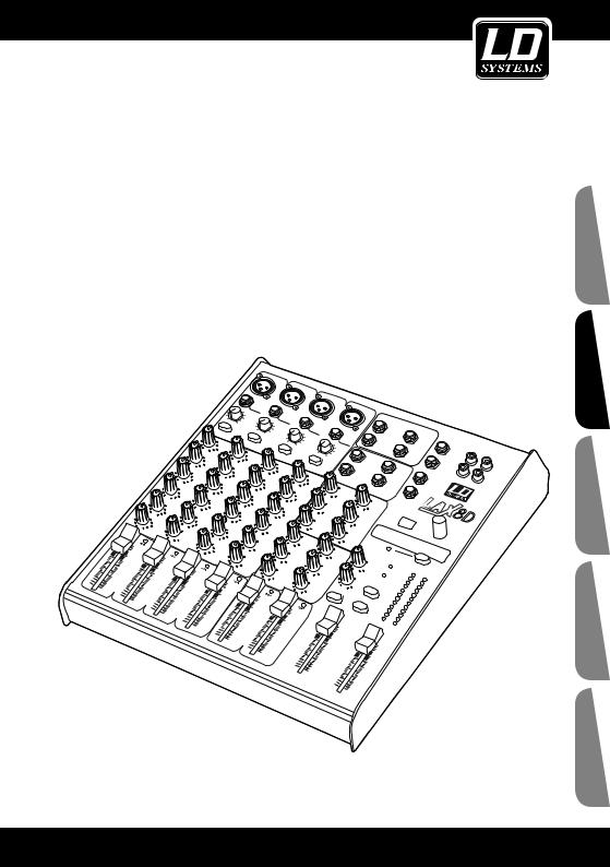
FEATURES:
The 8-Channel Mixing Console is designed for professional application. It will provide the following features:
•4 MIC Input Channels with gold plated XLRs and balanced Line Inputs.
•24-bit DSP effect built in.
•2 Stereo Input Channels with balanced TRS Jacks.
•Ultra-low noise discrete Mic Preamps with +48V Phantom Power.
•2 additional multi-functional Stereo Line Inputs.
•Extremely high headroom offering more dynamic range.
•Balanced Inputs for highest signal integrity.
•Warm , natural 3-band EQ on each channel.
•Peak LEDs and switchable low-cut Filter on each Channel.
•2 AUX Sends per channel for external effects and monitoring.
•Balanced TRS and XLR outputs , Control Room and Headphone Outputs.
•2-Track Inputs assignable to Main Mix , Control Room / Headphone Output.
•Highly accurate 12 segment Bar graph Meters.
•Inserts on MIC channels.
•Performance and excellent noise figures
•Rugged construction ensures long life even under the most demanding conditions
ENGLISH
POLSKIFRANCA FRANCAISESPAÑOL FRANCAIS DEUTSCH
5

ENGLISH
POLSKIFRANCA FRANCAISESPAÑOL FRANCAIS DEUTSCH
READY TO START:
Please check the AC voltage available in your country before connecting your mixer to the AC socket.
Be sure that the main power switch is turned off before connecting the mixer to the AC socket.Also, you should make sure that all input and output controls are turned down. This will avoid damage to your speakers and avoid excessive noise.
Always turn on the mixer before the power amplifier; turn off the mixer after the power amplifier.
Before connecting and disconnecting the unit from the power source always turn off the unit.
Do not use solvents to clean your mixer. A dry and clean cloth will be OK.
6

CONTROL ELEMENTS:
ENGLISH
POLSKIFRANCA FRANCAISESPAÑOL FRANCAIS DEUTSCH
7
ENGLISH
POLSKIFRANCA FRANCAISESPAÑOL FRANCAIS DEUTSCH
CONTROL ELEMENTS:
MIC 1
1
BAL OR  UNBAL
UNBAL
LINE IN 1
2
+15dB -25dB LINE
0dB 40dB MIC
3
LOW CUT 75Hz 18dB/Oct
LINE IN 5/6 |
LINE IN 7/8 |
|
LEFT(MONO) |
LEFT(MONO) |
|
RIGHT |
RIGHT |
4 |
1MONO MIC/LINE CHANEL
These are channel 1~4. You can connect balanced, low impedance microphones or a low level signal to the XLR socket. On the 1/4“ phone jack you can connect either a microphone or a line level instrument such as synthesizers, drum machines, effect processors or any other line level signal.
Note:You shall never connect an unbalanced microphone to the XLR socket if you do not want to damage both the microphone and the Mixer. Also, it is not possible to simultaneously use both the MIC & LINE inputs on the same channel, use only one of them for the appropriate source on each channel.
PHANTOM POWER +48 Volts
It is available only on the XLR input sockets.
Do not connect non-phantom equipment to the MIC input when phantom power is on.
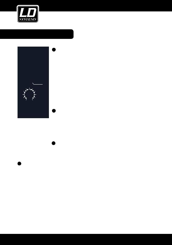
2INPUT LEVEL SETTING
This control is provided with 2 different indication rings: one is for the MIC input and the other for the LINE input. When you use a MIC input you shall read the
OUTSIDE ring (0~40dB); when you use a LINE input you shall read the INSIDE ring (+15~-25dB). For optimum operation you shall set this control in a way that the PEAK LED will blink only occasionally in order to avoid distortion on the input channel.
3LOW CUT SWITCH
By pressing this button you will activate a 75Hz low frequency filter with a slope of 18dB per octave.You can use this feature to reduce the hum noise caused by the mains power supply, or the stage rumble while using a microphone.
4STEREO INPUT (CH5~CH8)
They are organized in stereo pair and provided with 1/4“ TRS sockets. Use the left input to connect a mono input signal to the STEREO INPUT-this way the signal will appear on both left & right sides. This trick is called „jack normalling“.
8

CONTROL ELEMENTS:
0 |
5 |
3-BAND-EQUALIZER |
EQ |
HI |
|
|
HI |
|
|
12kHz |
This is the treble control. You can use it to get rid of high frequency noises or to |
-15 |
+15 |
boost the sound of cymbals or the high harmonics of the human voice. |
0 |
|
The gain range goes from -15dB to +15dB with a center frequency of 12kHz. |
 2.5kHzMID 5
-12 +12
0
LOW 80Hz
-15 +15
1  0
0  AUX
AUX
|
|
PRE |
-8 |
+15 |
6 |
2 |
0 |
DFX |
|
|
|
|
|
POST |
|
|
(PRE) |
-8 |
+15 |
|
PAN
7
L R
PEAK 8
10 dB 5
0
-5
-10
9
-15
-20
MID
This is the midrange control. It can affect most fundamental frequencies of all musical instruments and human voice. An attentive use of this control will give you a very wide panorama of sound effects.The gain range goes from -12dB to +12dB and the center frequency is 2.5kHz.
LOW
This is the bass control. It is used to boost male voice, kickdrum or bass guitar.
The gain range goes from -15dB to +15dB and the center frequency is 80Hz.
6AUX-CONTROL
These two controls are used to adjust the level of signal sent to AUX bus 1&2, and this adjustment doesn‘t affect the main mix output signal at all.
AUX1 is configured as PRE fader, the signal is sent out before the channel fader and will not be affected by the channel fader,AUX2 is configured as POST fader, the signal is sent out after the channel fader and will be affected by the channel fader. However, it can also be configured as PRE fader through internal modification.
7PAN
This is the PANORAMA control, or balance control. You can adjust the stereo image of the signal via this control. Keep this control in center position and your signal will be positioned in the middle of stage. Turn this control fully counterclockwise and the signal will be present only on the left speaker and vice-versa.
-30 |
8 PEAK-LED |
-40 |
Inside your 8-Channel Mixing Console the audio signal is monitored in several |
¡ |
|
-60 |
|
1different stages and then sent to the PEAK LED. When this LED blinks, it warns you that you are reaching signal saturation and possible distortion. The PEAK
LED will blink with a level that is 6dB before actual clipping.
9LEVEL
This fader will adjust the overall level of this channel and set the amount of signal sent to the main output.
10MAIN MIX LEVEL
This fader is used to set the amount of signal sent to the MAIN MIX OUTPUT and TAPE OUT.
ENGLISH
POLSKIFRANCA FRANCAISESPAÑOL FRANCAIS DEUTSCH
9

ENGLISH
POLSKIFRANCA FRANCAISESPAÑOL FRANCAIS DEUTSCH
CONTROL ELEMENTS: |
|
|
|||||
|
|
|
|
|
|
|
11 PHONES/CONTROL ROOM |
|
|
|
|
|
PROGRAM (PUSH) |
This fader sets the amount of signal sent to |
|
|
|
|
|
|
the CONTROL ROOM OUTPUT and PHONES. |
||
|
|
88 |
|
|
|
||
|
18 |
|
|
19 |
12 2-TRACK SIGNAL PATH |
||
|
|
|
|
|
|||
|
|
|
|
|
If you push down the 2TK TO CONTROL |
||
|
|
|
FUNCTION |
|
|
ROOM button, the 2 TRACK IN signal will be |
|
|
|
10-19 |
Echo+Verb |
60-69 Rotary |
|
||
|
|
|
routed into the CONTROL ROOM OUTPUT |
||||
|
|
00-09 |
Echo |
50-59 Vocal |
|
|
|
|
|
20-29 |
Tremolo |
70-79 Small Room |
|
and the level will be adjusted by the |
|
|
|
30-39 |
Plate |
80-89 Flange+Verb |
|
||
|
|
40-49 |
Leslie |
90-99 Large Hall |
|
PHONES/CONTROL ROOM knob. |
|
|
|
|
|
|
|
|
|
|
|
20 |
|
|
|
21 |
If you push the 2TK TO MIX button the 2 |
|
|
|
|
|
TRACK IN signal will be routed into the MAIN |
||
|
|
PEAK/MUTE |
|
|
|
||
|
|
|
DFX MUTE |
MIX OUTPUT and will be adjusted by the |
|||
|
|
|
|
|
|||
|
|
|
|
|
|
|
|
|
|
|
|
|
|
|
MAIN MIX LEVEL knob. |
|
0 |
|
|
16 |
|
CLIP |
Note: you can push down these two buttons |
|
1 |
|
|
simultaneously, the 2 TRACK IN signal will be |
|||
|
PHANTOM |
|
|
+10 |
|||
|
|
|
|
|
|
rounted into both CONTROL ROOM OUTPUT |
|
|
|
|
|
17 |
|
+7 |
|
|
|
|
|
|
and MAIN MIX OUTPUT, and the level of two |
||
|
-8 |
+15 |
PWR |
|
|
+4 |
|
|
|
|
|
+2 |
output signals will be adjusted by respective |
||
|
AUX RTN 1 |
|
|
|
control knob. |
||
14 |
0 |
|
2TK TO |
|
|
0 |
|
|
|
2 |
|
|
|
-2 |
13 |
|
|
|
|
|
|
-4 |
13 OUTPUT LEVEL LED DISPLAY |
|
8 |
+15 |
MAIN MIX |
|
|
-7 |
This stereo 12 segments LED meter will indi- |
|
- |
|
|
cate the level of overall output signal. |
|||
|
AUX RTN 2 DFX |
12 |
|
|
-10 |
||
15 |
|
|
|
|
|
-20 |
14 AUX RETURN CONTROL |
|
|
|
|
|
-30 |
||
|
EFX TO AUX 1 |
CONTROL ROOM |
L |
R |
This switch routes the signal that is present |
||
|
|
|
OUTPUT LEVEL |
at the AUX RETURN 2 jacks to AUX 1 output |
|||
|
|
|
|
|
|
|
|
|
|
PHONES |
|
MAIN MIX |
so that the effect can be heard in the |
||
|
|
|
monitor mix. |
||||
|
|
CONTROL ROOM |
|
LEVEL |
|
||
|
|
|
10 |
|
|
10 |
15 EFX TO AUX |
|
|
|
dB |
|
|
dB |
|
|
|
|
5 |
|
|
5 |
These two controls adjust the level of the |
|
|
|
|
|
|
|
|
|
|
|
0 |
|
|
0 |
signal present at the AUX RETURNS 1&2 |
|
|
|
-5 |
|
|
-5 |
jacks. The signal is summed, or mixed into |
|
|
|
-10 |
|
|
-10 |
the main L/R mix bus. |
|
|
|
|
|
|
||
|
|
|
-15 |
|
|
-15 |
16 PHANTOM-LED |
|
|
|
|
|
|
|
|
|
|
|
-20 |
|
|
-20 |
This LED indicates when the Phantom Power |
|
|
|
-30 |
|
|
-30 |
is switched on. |
|
|
|
-40 |
|
|
-40 |
|
|
|
|
-60 |
|
|
-60 |
|
|
11 |
|
|
|
|
|
10 |
10
CONTROL ELEMENTS:
17PWR-LED (POWER)
This LED indicates when the Power is on in your mixer.
18BIT DIGITAL EFFECTS
Displays the selected preset.
19PRESETS SELECTOR
Adjust this knob to select the right effect you wish to perform. There is a total of 100 presets available: Echo,
Vocal, Plate and versatile two-effect combination.When you found the right preset, please push this knob to confirm this selection.
20PEAK/MUTE-LED
This LED lights up when the input signal is too strong. In case of the digital effect module being muted, this LED also lights up.
21DFX MUTE-TASTE
This switch is used to activate/deactivate the effect facility. Sometimes, you can also use the DFX FOOT
SWITCH for convenient operation.
22STEREO AUX RETURNS
Use these stereo 1/4“ sockets to return the sound of an effect unit to the main mix. You can also use them as extra auxiliary inputs, but they are primarily used to connect the output of external effect processors. Note:
The AUX RETURN2 (DFX) is connected with the output of the internal digital effects, but, this signal flow will be broken, if you have any external signal inserted from these 2 sockets of AUX RETURN2.
STEREO AUX RETURNS |
|
23 AUX SENDS |
||
|
These 1/4“ sockets are used to send out the signal from the |
|||
1 |
2 |
|
|
|
|
|
|
|
AUX bus to external devices such as effects and sound |
LEFT(MONO) 22 |
|
LEFT |
|
processors, they also can be used as monitoring outputs by |
|
|
|
|
connecting a power amplifier and monitor speaker. |
RIGHT |
|
RIGHT |
|
|
|
|
FOOT SW |
||
AUX SENDS |
|
24 |
||
|
|
This socket is used to connect external footswitch for a convenient operation, it has the |
||
1 |
|
|
||
|
|
|
same function as the DFX MUTE button. |
|
23 |
|
25 |
PHONES |
|
2 |
|
|||
|
|
This socket will be used to send out the mix signal to a pair of headphones. |
||
|
|
|
||
|
|
|
|
|
ENGLISH
POLSKIFRANCA FRANCAISESPAÑOL FRANCAIS DEUTSCH
11

ENGLISH
POLSKIFRANCA FRANCAISESPAÑOL FRANCAIS DEUTSCH
CONTROL ELEMENTS:
24 
FOOT SW
25 
PHONE
2-TRACK IN/OUT
26TAPE IN
Use the Tape input if you wish to listen to your mixer from a Tape Recorder or DAT. You can assign the signal coming from the Tape Recorder(or DAT) either to CONTROL ROOM
OUTPUT or to the MAIN MIX OUTPUT by using the 2TK TO select button.
2-TRACK IN/OUT |
|
27 TAPE OUT |
|
L |
These 1/4“ RCA sockets will route the main mix into a Tape |
|
Recorder. |
|
|
|
|
26 |
27 |
|
R
TAPE IN TAPE OUT
12

|
|
|
|
|
|
BACK PANEL: |
|
|
30 |
|
|
MODEL |
CAUTION |
POWER |
PHANTOM |
MAIN MIX OUTPUT(BAL/UNBAL) |
|
|||
|
|
|
|
RISK OF ELECTRIC SHOCK |
||
|
|
|
|
|
|
DO NOT OPEN |
|
|
|
L |
L |
SERIAL |
WARNING: SHOCK HAZARD - DO NOT OPEN |
|
|
|
AVIS: RISQUE DE CHOC ELECTRIQUE - NE PAS OUVRIR |
|||
|
|
|
|
|
|
|
ON |
OFF |
|
|
|
|
|
4 |
3 |
2 |
1 |
INSERT |
INSERT |
INSERT |
INSERT |
|
RIGHT |
R |
R |
|
|
LEFT |
|
|
|
|
AC INPUT |
|
OUTPUT CTRL ROOM |
|
28 |
29 |
31 |
32 |
33 |
28POWER ON/OFF SWITCH
This switch is used to turn the Main Power ON and OFF.
29AC INPUT CONNECTOR
This connector is used to connect the supplied AC adapter.
30PHANTOM ON/OFF SWITCH
This switch will apply +48 Volt Phantom Power only to the 6 XLR inputs sockets.When these XLR sockets are connected with devices that do not require Phantom Power, please make sure the Phantom Power is turned off, otherwise, this may damage the device and mixer.
31MAIN MIX OUTPUT
The stereo output is supplied both XLR and 1/4“ TRS sockets, which are used to send the audio signal to an amplifier.Through the main mix level control, you can adjust the output level from - to +15dB.
32CONTROL ROOM OUTPUT
These 1/4“ phone sockets will be used to send the signal to studio monitor speakers or to a second set of PA.
33INSERT
Insert sockets are provided for each mono MIC channel. It can allow you patch external signal processing devices into signal path via a TRS connector, the signal will be taken out after the input gain control (TRIM), and sent to an external processor such as a compressor-limiter, then returned into the same channel immediately before the EQ section.
Note: Usually, insert connections require a special stereo-splitting Y-cord to be connected, known as TRS connector (Tip Send/Ring Return).
ENGLISH
POLSKIFRANCA FRANCAISESPAÑOL FRANCAIS DEUTSCH
13

ENGLISH
POLSKIFRANCA FRANCAISESPAÑOL FRANCAIS DEUTSCH
WIRING CONFIGURATION:
Ok, you have got to this point and you are now in the position to successfully operate your 8-Channel Mixing Console. However, we advise you to read carefully the following section to be the real master of your own mixer. Not paying enough attention to the input signal level, to the routing of the signal and the assignment of the signal will result in unwanted distortion, a corrupted signal or no sound at all. So you should follow these procedures for every single channel:
•Before connecting mics or instruments, make sure that the power of all your systems components including the mixer is turned off. Also, make sure that all input and output controls of your mixer are turned down. This will avoid damage to your speakers and avoid excessive noise.
•Properly connect all external devices such as mics, power amplifiers, speakers, effect processor etc.
•Now, turn on the power of any peripheral devices, then power up the mixer.
Note: the power amplifier or powered monitors shall be turned on after the mixer and turned off before the mixer.
•Set the output level of your mixer or the connected power amplifier at no more than 75%.
•Set the CONTROL ROOM/PHONE level at no more than 50%.
•Position HI, MID and LOW EQ controls on middle position.
•Position panoramic (PAN/BAL) control on center position.
•While speaking into the mic(or playing the instrument), adjust the channel Level control so that the PEAK LED will blink occasionally, in this way you will maintain good headroom and idea dynamic range.
•You can shape the tone of each channel by adjusting the equalizer controls as desired.
•Now repeat the same sequence for all input channels.The main LED could move up into the red section, in this case you can adjust the overall output level through the MAIN MIX control.
•You can select desired DSP sound effects via the PRESET and VARIATION controls.
14

WIRING CONFIGURATION:
You can connect unbalanced equipment to balanced inputs and outputs. Simply follow these schematics.
Sleeve |
Tip |
Ring=Right Signal |
Ring |
||
Strain Clamp |
|
Tip=Left Signal |
Sleeve=Ground/Screen
Use for Headphone, Stereo Return
1/4“ Stereo (TRS) Jack Plug
Sleeve Tip
Strain Clamp |
Tip=Signal |
Sleeve=Ground/Screen
Use for Mono Line In, Mono 1/4“Jack Plugs 1/4“ Mono (TS) Jack Plug
Sleeve |
Tip |
Ring |
Ring=Return Signal |
|
|||
Strain Clamp |
|
|
Tip=Send Signal |
Sleeve=Ground/Screen
Use for Pre-Gain Channel Inserts
1/4“ Stereo (TRS) Jack Plug
Hot (+) |
Ground/Screen |
Hot (+) |
3 |
|
|
Ground/Screen |
2 |
1 |
2 |
1 |
|
||
|
3 |
|
|
|
|
|
Cold (-) |
|
Cold (-) |
||||
Use for Balanced Mic Inputs |
|
Use for Main output |
|
|
|
|
(For unbalanced use, connect pin 1 to 3) |
(For unbalanced use, leave pin 3 unconnected) |
|||||
3-pin XLR male plug |
|
3-Pin XLR line socket |
|
|
|
|
(seen from soldering side) |
|
(seen from soldering side) |
||||
ENGLISH
POLSKIFRANCA FRANCAISESPAÑOL FRANCAIS DEUTSCH
15

ENGLISH
POLSKIFRANCA FRANCAISESPAÑOL FRANCAIS DEUTSCH
WIRING CONFIGURATION:
Ring=Return Signal (Connected together)
To Channel
Insert
Sleeve=Ground/Screen
Tip=Signal
To Tape or
FX Input
Sleeve=Ground/Screen
‚Tapped‘ Connection Direct Output Lead (Enables the Insert to be used as a Direct Output while maintaining the channel signal flow)
|
|
To Processor |
|
|
Input |
|
Tip |
Sleeve=Ground/Screen Tip=Send Signal |
|
|
|
|
|
To Channel |
|
|
Insert |
Sleeve |
Ring |
Ring=Return Signal |
|
|
To Processor |
|
|
Output |
Y-Stereo lead for insert Connection
(To be used when the processor does not employ a single jack connection for the In/Out Connections)
16

|
|
|
PRESET LISTE: |
|
|
|
|
|
|
No. |
PRESET |
DESCRIPTION |
PARAMETER |
|
|
|
|
|
|
|
|
|
|
|
00 - 09 |
Echo |
Reproduce the sound in input |
Delay Time: 145 ms - 205 ms |
|
|
|
on the output after a lapse of |
|
|
|
|
time or delay. |
|
|
|
|
|
|
|
10 - 19 |
Echo & Verb |
Echo with Room effect. |
Delay Time: 208 ms - 650 ms |
|
|
|
|
Decay Time 1.7 s - 2.1 s |
|
|
|
|
|
|
20 - 29 |
Tremolo |
Amplitude modulation of the |
Rate: 0.6 Hz - 5 Hz |
|
|
|
signal. |
|
|
|
|
|
|
|
30 - 39 |
Plate |
Simulate the sound of classic |
Decay Time: 0.9 s - 3.6 s |
|
|
|
EMT plate reverb. |
|
|
|
|
|
|
|
40 - 49 |
Chorus |
Recreate the illusion of more |
Rate: 0.92 Hz - 1.72 Hz |
|
|
|
than one instrument from a |
|
|
|
|
single instrument sound. |
|
|
|
|
|
|
|
50 - 59 |
Vocal |
Simulate a small space with |
Rev. decay time: 0.8 s - 0.9 s |
|
|
|
slight reverberation. |
Pre-delay: 0 ms - 45 ms |
|
|
|
|
|
|
60 - 69 |
Rotary |
Simulate the sound effect |
Modulation depth: |
|
|
|
achieved by rotating horn spea- |
20 % - 80 % |
|
|
|
kers and a bass cylinder. |
|
|
|
|
|
|
|
70 - 79 |
Small Room |
Simulate a bright studio room. |
Decay Time 0.7 s - 2.1 s |
|
|
|
|
Pre-delay: 20 ms - 45 ms |
|
|
|
|
|
|
80 - 89 |
Flanger & |
Classic flanger effect in combi- |
Decay Time: 1.5 s - 2.9 s |
|
|
Verb |
nation with reverb. |
Rate: 0.8 Hz - 2.52 Hz |
|
|
|
|
|
|
90 - 99 |
Large Hall |
Simulates a large room rever- |
Pre-delay: 23 ms - 55 ms |
|
|
|
berated sound 3.6-5.4 s. |
|
|
|
|
|
|
|
ENGLISH
POLSKIFRANCA FRANCAISESPAÑOL FRANCAIS DEUTSCH
17

ENGLISH
POLSKIFRANCA FRANCAISESPAÑOL FRANCAIS DEUTSCH
SPECIFICATIONS:
MONO INPUT CHANNELS
Microphone input: electronically balanced, discrete input configuration.
Frequency response: 10 Hz … 45 kHz, +/-3 dB Distortion (THD+N): 0,005% @ +4 dBu, 1 kHz Gain range: 0 dB … 40 dB (MIC)
SNR (Signal to noise ratio): 100 dB
Line input: electronically balanced
Frequency response: 10 Hz … 45 kHz, +/-3 dB Distortion (THD+N): 0,005% @ +4 dBu, 1 kHz Gain range: +15 dBu … -25 dBu (LINE)
STEREO INPUT CHANNELS
Line input: asymmetric
Frequency response: 10 Hz … 45 kHz, +/-3 dB Distortion (THD+N): 0,005% @ +4 dBu, 1 kHz
IMPEDANCES
Microphone input: 3,6 kOhm
All other inputs: 10 kOhm or greater
Tape out: 1 kOhm
All other outputs: 120 Ohm
EQUALIZATION
Hi Shelving: +/-15 dB @ 12 kHz
Mid Bell: +/-12 dB @ 2,5 kHz
Low Shelving: +/-15 dB @ 80 Hz
DSP-SECTION
A/D and D/A converters: 24 Bit DSP resolution: 24 Bit
Type of effects: Echo, Echo+Verb,Tremolo, Plate, Chorus,Vocal, Rotary, Small Room, Flanger + Verb,
Large Hall Presets: 100
Controls: Preset-Selector, Effect Bypass
MAIN MIX SECTION
Noise (Bus noise): Fader 0 dB, channels muted: -100 dBr (ref. +4 dBu)
Fader 0 dB, all input channels assigned and set to Unity Gain: -90 dBr (+4 dBu)
Max output: +22 dBu (XLR, balanced ); +22 dBu (6.3- mm jack, unbalanced)
AUX Returns, Gain: OFF … +15 dB AUX-Sends, max. : +22 d Bu
POWER SUPPLY (AC/AC Adaptor)
Main voltage
USA/Canada 100 – 120 V, ~60 Hz,
Europe 210 – 230 V, ~50 Hz
U.K / Australia 240 V, ~50 Hz
Power consumption: 18 W
PHYSICAL
Dimensions (WxDxH): 352 x 272 x 80/40 mm Gewicht: 3,4 kg without AC adapter.
Since all our products are constantly controlled and improved, technical changes are possible without prior notice.
18

MANUFACTURER´S DECLARATIONS:
LIMITED WARRANTY
This Limited Warranty applies to the Adam Hall, LD Systems, Defender, Palmer and Eminence branded products.
The statutory warranty rights towards the seller are not affected by this guarantee. In fact, it justifies, additional independent warranty claims towards Adam Hall.
Adam Hall warrants that the Adam Hall product you have purchased from Adam Hall or from an Adam Hall authorized reseller is free from defects in materials or workmanship under normal use for a period of 2 or 3 years from the date of purchase.
The Limited Warranty Period starts on the date of purchase. In order to receive warranty services you are required to provide proof of the purchase date. Your dated sales or delivery receipt, showing the date of purchase, is your proof of the purchase date. Should products of the brands named above be in need of repair within the limited warranty period, you are entitled to warranty services according to the terms and conditions stated in this document.
This Limited Warranty extends only to the original purchaser of this Adam Hall branded product and is not transferable to anyone, who obtains ownership of the Adam Hall branded product from the original purchaser. During the Limited Warranty Period, Adam Hall will repair or replace the defective component parts or the product. All component parts or hardware products removed under this Limited Warranty become the property of Adam Hall.
In the unlikely event that your Adam Hall product has a recurring failure, Adam Hall, at its discretion, may elect to provide you with a replacement unit of Adam Hall´s choice that is at least equivalent to your Adam Hall branded product in hardware performance.
Adam Hall does not warrant that the operation of this product will be uninterrupted or error-free. Adam Hall is not responsible for damage that occurs as a result of your failure to follow the instructions included with the Adam Hall branded product.
This Limited Warranty does not apply,
-to wear parts (e.g. accumulator)
-to any product from which the serial number has been removed or that has been damaged or rendered defective as the result of an accident
-in case of, misuse, abuse, or other external causes
-by operation outside the usage parameters stated in the user´s documentation shipped with the product
-by use of spare parts not manufactured or sold by Adam Hall
-by modification or service by anyone other than Adam Hall
These terms and conditions constitute the complete and exclusive warranty agreement between you and Adam Hall regarding the Adam Hall branded product you have purchased.
ENGLISH
POLSKIFRANCA FRANCAISESPAÑOL FRANCAIS DEUTSCH
19
ENGLISH
POLSKIFRANCA FRANCAISESPAÑOL FRANCAIS DEUTSCH
LIMITATION OF LIABILITY
If your Adam Hall branded hardware product fails to work as warranted above, your sole and exclusive remedy shall be repair or replacement. Adam Halls’ maximum liability under this limited warranty is expressly limited to the lesser of the price you have paid for the product or the cost of repair or replacement of any hardware components that malfunction in conditions of normal use.
Adam Hall is not liable for any damages caused by the product or the failure of the product, including any lost profits or savings or special, incidental, or consequential damages. Adam Hall is not liable for any claim made by a third party or made by you for a third party.
This limitation of liability applies whether damages are sought, or claims are made, under this Limited Warranty or as a tort claim (including negligence and strict product liability), a contract claim, or any other claim. This limitation of liability cannot be waived or amended by any person. This limitation of liability will be effective even if you have advised Adam Hall of an authorized representative of Adam Hall of the possibility of any such damages. This limitation of liability however, will not apply to claims for personal injury.
This Limited Warranty gives you specific legal rights. You may also have other rights that may vary from state to state or from country to country. You are advised to consult applicable state or country laws for a full determination of your rights.
REQUESTING WARRANTY-SERVICE
To request warranty service for the product, contact Adam Hall or the Adam Hall authorized reseller from which you purchased the product.
EG-DECLARATION OF CONFIRMITY
These products meet the essential requirements as well as the further standards of the EU Directives 199/5/EU, 89/336/EU.
CORRECT DISPOSAL OF THIS PRODUCT (ELECTRICAL WASTE) 
(Applicable in the European Union and other European countries with separate collection systems)
This marking shown on the product or its literature, indicates that it should not be disposed with other household wastes at the end of its working life. To prevent possible harm to the environment or human health from uncontrolled waste disposal, please separate this from other types of wastes and recycle it responsibly to promote the sustainable reuse of material resources.
Household users should contact either the retailer where they purchased this product, or their local government office, for details on where and how they can recycle this item in an enviromentally friendly manner.
Business users should contact their supplier and check the terms and conditions of the purchase contract. This product should not be mixed with other commercial wastes for disposal
20
WEEE-DECLARATION |
|
NOTES: |
|
|
|
Your LD-Systems product was developed and manufactured with high quality materials and components wich can be recycled and/or reused. This symbol indicates that electrical and electronic equipment must be disposed of separately from normal waste at the end of its operational lifetime.
Please dispose of this product by bringing it to your local collection point or recycling centre for such equipment. This will help to protect the environment in which we all live.
BATTERIES AND ACCUMULATORS 
The supplied batteries or rechargeable batteries can be recycled. Please dispose of them as special waste or return them to your specialist dealer. In order to protect the environment, only dispose exhausted batteries.
Adam Hall GmbH, all rights reserved. The technical data and the functional product characteristics can be subject to modifications. The photocopying, the translation, and all other forms of copying of fragments or of the integrality of this user’s manual is prohibited.
ENGLISH
POLSKIFRANCA FRANCAISESPAÑOL FRANCAIS DEUTSCH
21

ENGLISH
POLSKFRANCAI FRANCAISESPAÑOL FRANCAIS DEUTSCH
Mit einem Produkt von LD Systems haben Sie die richtige Wahl getroffen!
Dieses Gerät wurde unter hohen Qualitätsanforderungen entwickelt und gefertigt, um viele Jahre einen reibungslosen Betrieb zu gewährleisten. Dafür steht LD Systems mit seinem Namen und der langjährigen Erfahrung als
Hersteller hochwertiger Audioprodukte.
Bitte lesen Sie diese Bedienungsanleitung sorgfältig, damit Sie Ihren neuen Verstärker von LD Systems schnell optimal einsetzen können.
Weitere Informationen zu Produkten von LD Systems erhalten Sie auf unserer Internet-Seite WWW.LD-SYSTEMS.COM.
22
LD LAX8D
8 KANAL MISCHPULT MIT DSP
ENGLISH
POLSKFRANCAI FRANCAISESPAÑOL FRANCAIS DEUTSCH
23

ENGLISH
POLSKFRANCAI FRANCAISESPAÑOL FRANCAIS DEUTSCH
VORSICHTSMASSNAHMEN:
1.Bitte beachten Sie die Sicherheitshinweise und studieren Sie diese Anleitung sorgfältig.
2.Bewahren Sie alle Hinweise und Anleitungen sicher auf.
3.Verwenden Sie das Gerät nur in der vorgesehenen Art und Weise.
4.Beachten die in Ihrem Land geltenden Entsorgungsgesetze.Trennen Sie bei der Entsorgung bitte Plastik und
Papier bzw. Kartonagen von einander.
5.Sollte Ihr Gerät nicht mehr ordnungsgemäß funktionieren, Flüssigkeiten ausgesetzt werden oder auf sonstige Art und Weise beschädigt sein, überlassen Sie bitte jegliche Reparaturen ausschließlich autorisiertem Fachpersonal.
6.Halten Sie das Gerät von Hitzequellen wie z.B. Ofen, Heizkörper, oder sonstige Quellen (auch Verstärker) fern. Sorgen Sie dafür dass das Gerät immer so installiert ist, dass es ausreichend gekühlt wird und nicht überhitzt.
7.Überprüfen Sie alle Verbindungen nach dem Sie das Gerät angeschossen haben um Schäden oder Unfälle zu vermeiden.
8.Verwenden Sie ausschließlich stabile und passende Stative bzw. Befestigungen wenn das Gerät fest installiert wird. Stellen Sie sicher, dass das Gerät sicher installiert ist und nicht herunterfallen kann.
CAUTION |
RISK OF ELECTRIC SHOCK |
DO NOT OPEN |
ACHTUNG:
Entfernen Sie niemals die Abdeckung, da sonst die Gefahr eines elektrischen Schocks besteht.
Im Inneren des Gerätes befinden sich keine Teile, die vom Bediener gewartet oder repariert werden können. Lassen Sie Reparaturen ausschließlich von qualifiziertem Servicepersonal durchführen.
Dieses Symbol warnt vor nichtisolierten, gefährlichen Spannungen im Geräteinneren, die einen gefährlichen Schlag verursachen können.
Dieses Symbol kennzeichnet wichtige Bedienungsund Wartungshinweise.
Vorsicht! Hohe Lautstärke!
Diese Übertragungsanlage wird von Ihnen professionell eingesetzt. Daher unterliegt der Gebrauch bei gewerblicher Nutzung den Regeln und Vorschriften der zuständigen Berufsgenossenschaft.Adam Hall als Hersteller ist daher verpflichtet, Sie auf möglicherweise bestehende gesundheitliche Risiken ausdrücklich hinzuweisen.
Mit diesen Lautsprechern können hohe Schalldrücke erzeugt werden. 85db ist der Schalldruck, der laut Gesetz als maximal zulässiger Wert über die Dauer eines Arbeitstages auf Ihr Gehör einwirken darf. Er wird nach den Erkenntnissen der Arbeitsmedizin als Berurteilungspegel zu Grunde gelegt. Höhere Lautstärken oder längere Einwirkzeit können Ihr Gehör schädigen. Bei höheren Lautstärken muss die Hörzeit verkürzt werden, um eine Schädigung auszuschließen. Sichere Warnsignale dafür, dass Sie sich zu lange zu lautem Geräusch ausgesetzt haben, sind:
-Sie hören Klingeloder Pfeifgeräusche in den Ohren!
-Sie haben den Eindruck, hohe Töne nicht mehr wahrzunehmen!
24

FEATURES:
Der LAX8D-Mixer wurde für den professionellen Einsatz entwickelt und bietet folgende Ausstattung:
•4 Mikrofonkanäle mit vergoldeten XLR-Anschlüssen und symmetrischen Line-Eingängen
•Integrierter digitaler 24-Bit-Effektprozessor
•2 Stereo-Kanalzüge mit symmetrischen Klinkeneingängen (TRS)
•Rauscharme, diskrete Mikrofon-Preamps mit +48-Volt-Phantomspeisung
•2 zusätzliche Stereo-Line-Eingänge
•Hohe Aussteuerungsreserve und Dynamik
•Symmetrische Eingänge für störungsfreie Signalübertragung
•Warm und natürlich klingende 3-Band-Equalizer in allen Kanalzügen
•Peak-LEDs und schaltbare Trittschallfilter in allen Kanalzügen
•2 AUX-Sends pro Kanal für externe Effektgeräte und Monitoring
•Symmetrische Klinkenund XLR-Anschlüsse, Regieund Kopfhörer-Ausgänge
•2-Track-Eingänge mit Routing-Möglichkeiten auf Summen-, Regieund Kopfhörer-Ausgänge
•Hochpräzise Aussteuerungsanzeige (12 Segmente)
•Mikrofonkanäle mit Inserts
ENGLISH
POLSKFRANCAI FRANCAISESPAÑOL FRANCAIS DEUTSCH
25

ENGLISH
POLSKFRANCAI FRANCAISESPAÑOL FRANCAIS DEUTSCH
ERSTE SCHRITTE:
Überprüfen Sie vor Anschluss Ihres LAX8D-Mixers, dass die Stromversorgung mit der für das Gerät geeigneten
Netzspannung erfolgt.
Vergewissern Sie sich, dass der Mixer ausgeschaltet ist, bevor Sie ihn an das Stromnetz anschließen, und stellen
Sie alle Regler in “Null”-Stellung. Auf diese Weise vermeiden Sie Schäden an Ihren Lautsprechern durch laute Einschaltgeräusche und hohe Pegel.
Schalten Sie immer zuerst den Mixer und danach den angeschlossenen Leistungsverstärker ein. Beim Ausschalten gilt die umgekehrte Reihenfolge: Schalten Sie zuerst den Leistungsverstärker und danach den Mixer aus.
Schalten Sie den LAX8D-Mixer stets aus, bevor Sie Verkabelungen vornehmen.
Verwenden Sie zur Reinigung des LAX8D keine Lösungsmittel, sondern ein sauberes, trockenes Tuch.
26

BEDIENELEMENTE:
ENGLISH
POLSKFRANCAI FRANCAISESPAÑOL FRANCAIS DEUTSCH
27

ENGLISH
POLSKFRANCAI FRANCAISESPAÑOL FRANCAIS DEUTSCH
BEDIENELEMENTE:
MIC 1
1
BAL OR  UNBAL
UNBAL
LINE IN 1
2
+15dB -25dB LINE
0dB 40dB MIC
3
LOW CUT 75Hz 18dB/Oct
LINE IN 5/6 |
LINE IN 7/8 |
|
LEFT(MONO) |
LEFT(MONO) |
|
RIGHT |
RIGHT |
4 |
1DIE MONOKANÄLE (MIC/LINE)
Die vier Mono-Kanalzüge bieten symmetrische XLR-Anschlüsse für niederohmige Mikrofone und anderes Equipment mit niedrigem Pegel. Zusätzlich stehen
6,3-mm-Klinkeneingänge für den Anschluss von Mikrofonen und Geräten mit Line-Pegel (z.B. Synthesizer, Drum-Computer, Effektprozessoren etc.) zur Verfügung.
Achtung: Schließen Sie niemals unsymmetrische Mikrofone an die XLR-Eingän- ge an, da auf diese Weise sowohl die Mikrofone als auch der Mixer beschädigt werden können. Darüber hinaus ist es nicht möglich, MICund LINE-Eingänge desselben Kanals gleichzeitig zu belegen.Verschiedene Signalquellen erfordern separate Kanäle.
+48-VOLT-PHANTOMSPEISUNG
Die XLR-Eingänge der Mono-Kanalzüge stellen +48-Volt-Phantomspannung zur
Speisung von Kondensatormikrofonen bereit.
Achtung: Schließen Sie bei eingeschalteter Phantomspeisung niemals Mikrofone ohne Phantomspeisung an die XLR-Eingänge an.
2EINSTELLEN DER EINGANGSVERSTÄRKUNG
Der Gain-Regler verfügt über zwei unterschiedliche Einteilungen: eine für Mikrofone und eine für Geräte mit Line-Pegel. Der äußere Ring (0 ~ 44 dB) bezieht sich auf Mikrofone, der innere (+15 ~ -30 dB) auf Geräte mit Line-Pegel.
Stellen Sie die Gain-Regler stets so ein, dass die Peak-LED oberhalb des Kanal-Faders nur gelegentlich aufleuchtet. Leuchtet die LED konstant, kann dies zu Verzerrungen führen.
3TRITTSCHALLFILTER (LOW CUT)
Die LOW CUT-Taste aktiviert ein Trittschallfilter (75 Hz, Flankensteilheit 18 dB/
Oktave) zur Reduzierung von tieffrequenten Störgeräuschen wie Netzbrummen oder Handgeräusche von Vokalmikrofonen.
4DIE STEREOKANÄLE (CH5-CH8)
Die Stereo-Kanalzüge sind jeweils als Stereopaare mit 6,3-mm-Klinkeneingängen (TRS) ausgeführt.
Mono-Signalquellen schließen Sie an den linken Klinkeneingang an.
28

BEDIENELEMENTE:
0 EQ
HI 12kHz
-15 +15
0
 2.5kHzMID 5
-12 +12
0
LOW 80Hz
-15 +15
1  0
0  AUX
AUX
|
|
PRE |
-8 |
+15 |
6 |
2 |
0 |
DFX |
|
|
|
|
|
POST |
|
|
(PRE) |
-8 |
+15 |
|
PAN
7
L R
PEAK 8
10 dB 5
0
53-BAND-EQUALIZER
HI
Über diesen Regler steuern Sie die hohen Frequenzen, d.h. Sie können dem entsprechenden Signal mehr Brillanz und Präsenz verleihen oder unerwünscht laute hohe Frequenzen absenken (Regelbereich -15 dB bis +15 dB, Mittenfrequenz 12 kHz).
MID
Über diesen Regler steuern Sie die mittleren Frequenzen, die wichtigsten Frequenzen für Musikinstrumente und die menschliche Stimme (Regelbereich -12 dB bis +12 dB, Mittenfrequenz 2,5 kHz).
LOW
Über diesen Regler steuern Sie die tiefen Frequenzen, d.h. Sie können z.B. einer Bassdrum, Bassgitarre oder männlichen Stimme mehr Fundament verleihen (Regelbereich -15 dB bis +15 dB, Mittenfrequenz 80 Hz).
6AUX-REGLER
Über diese beiden Regler steuern Sie die an die AUX-Wege 1 und 2 (Ausspielwege) gesendeten Signale. Das Summensignal (MAIN MIX) bleibt unbeeinflusst. AUX 1 kann über die PRE/POST-Taste PREoder POST-Fader geschaltet werden. In Position POST (Taste nicht gedrückt) erfolgt der Signalabgriff nach dem Kanal-Fader, so dass sich die für diesen Kanalzug eingestellte Lautstärke auch auf das AUX 1-Signal auswirkt. In Position PRE (Taste gedrückt) erfolgt der Signalabgriff vor dem Kanal-Fader, das AUX 1-Signal bleibt also vom KanalFader unbeeinflusst. Bei AUX 2 handelt es sich um einen “Post-Fader”-Weg.
-5 |
|
7 PAN |
|
|
|
||
-10 |
9 |
Die Mono-Kanalzüge des LAX8D verfügen über einen Panorama-Regler (PAN), |
|
|
|||
-15 |
die Stereo-Kanalzüge über einen so genannten Balance-Regler (BAL), die beide |
||
|
|||
-20 |
|
der Verteilung des Signals auf den rechten und linken Ausgangskanal dienen. |
-30
-40
-60 8 PEAK-LED
¡
1Inside your 8-Channel Mixing Console the audio signal is monitored in several different stages and then sent to the PEAK LED. When this LED blinks, it warns you that you are reaching signal saturation and possible distortion. The PEAK
LED will blink with a level that is 6dB before actual clipping.
9LEVEL
Über diesen Fader steuern Sie die Gesamtlautstärke des jeweiligen Kanalzugs, d.h. den Pegel, der an die Summenausgänge (MAIN MIX) ausgegeben wird.
ENGLISH
POLSKFRANCAI FRANCAISESPAÑOL FRANCAIS DEUTSCH
29

ENGLISH
POLSKFRANCAI FRANCAISESPAÑOL FRANCAIS DEUTSCH
BEDIENELEMENTE:
|
|
|
|
|
10 MAIN MIX LEVEL |
|
|
|
|
PROGRAM (PUSH) |
Über diesen Fader steuern Sie den Pegel des |
|
|
|
|
an die Summenausgänge (MAIN MIX) und |
|
|
88 |
|
|
||
18 |
|
19 |
den Recording-Ausgang (TAPE OUT) |
||
|
|
|
|||
|
|
|
überführten Signals. |
||
|
|
|
|
|
|
|
10-19 |
FUNCTION |
11 PHONES/CONTROL ROOM |
||
|
Echo+Verb |
60-69 Rotary |
Über diesen Fader steuern Sie den Pegel des |
||
|
00-09 |
Echo |
50-59 |
Vocal |
|
|
20-29 |
Tremolo |
70-79 |
Small Room |
an die Regie (CONTROL ROOM) und den |
|
30-39 |
Plate |
80-89 |
Flange+Verb |
|
|
40-49 |
Leslie |
90-99 |
Large Hall |
KopfhörerAusgang (PHONES) überführten |
|
|
|
|
|
|
|
20 |
|
|
21 |
Signals. |
|
|
|
|
||
|
PEAK/MUTE |
DFX MUTE |
|
12 2-TRACK WEG |
||
|
|
|
|
|
||
|
|
|
|
|
|
|
|
|
|
|
|
|
Bei gedrückter 2TK TO CONTROL |
|
0 |
|
16 |
CLIP |
|
ROOMTaste wird das 2-TRACK IN-Signal |
|
1 |
|
direkt auf den Regieausgang (CONTROL |
|||
|
PHANTOM |
+10 |
|
|||
|
|
|
|
|
ROOM) geroutet; den Pegel steuern Sie über |
|
|
|
|
17 |
+7 |
|
|
|
|
|
|
den PHONES/ CONTROL ROOM-Fader. Bei |
||
-8 |
+15 |
|
PWR |
+4 |
|
|
|
|
+2 |
|
gedrückter 2TK TO MIX-Taste wird das |
||
AUX RTN 1 |
|
|
|
2-TRACK IN-Signal auf den Summenaus- |
||
14 |
0 |
|
2TK TO |
0 |
|
|
|
|
2 |
|
-2 |
13 |
gang (MAIN MIX) geroutet; den Pegel steuern |
|
|
|
|
-4 |
|
Sie in diesem Fall über den MAIN MIX |
8 |
+15 |
|
MAIN MIX |
-7 |
|
LEVEL-Fader. Hinweis: Beide Tasten können |
- |
|
|
auch gleichzeitig gedrückt werden, so dass |
|||
AUX RTN 2 DFX |
|
12 |
-10 |
|
||
|
|
|
|
-20 |
|
das 2-TRACKSignal sowohl auf den Regie- |
15 |
|
|
|
-30 |
|
als auch auf den Summenausgang geroutet |
EFX TO AUX 1 |
|
CONTROL ROOM |
L |
R |
wird; die entsprechenden Pegel steuern Sie |
|
|
|
|
OUTPUT LEVEL |
über die zugehörigen Fader. |
||
|
|
|
|
|
|
|
PHONES |
MAIN MIX |
13 |
LED-PEGELANZEIGE |
CONTROL ROOM |
LEVEL |
|
|
10 |
10 |
|
Über die Stereo-Pegelanzeige (12 Segmente) |
|
überwachen Sie den Pegel des Ausgangssignals. |
||
dB |
dB |
|
5
 5
5
0 |
0 |
|
14 AUX RETURN |
-5 |
-5 |
|
Über diese beiden Regler steuern Sie die |
-10 |
-10 |
|
Return-Pegel der AUX-Return Wege 1&2, |
|
wobei die Signale dem Summenausgang L/R |
||
-15 |
-15 |
|
|
|
(MAIN MIX) hinzugemischt werden. |
||
|
|
|
|
-20 |
-20 |
|
|
-30 |
-30 |
|
15 EFX TO AUX |
-40 |
-40 |
|
Über diesen Schalter routen Sie das an AUX |
-60 |
-60 |
|
|
11 |
|
10 |
RETURN 2 anliegende Signal auf den AUX |
|
1-Ausgang, so dass der Effekt auch im |
||
|
|
|
|
|
|
|
MonitorMix zu hören ist – was sich in der |
|
|
|
Praxis als außerordentlich hilfreich erweist. |
30
 Loading...