


USER´S MANUAL
BEDIENUNGSANLEITUNG
MANUEL D`UTILISATION
MANUAL DE USUARIO
INSTRUKCJA OBSŁUGI
MANUALE D‘ USO
|
USB |
IC PLAYER |
|
MUS |
|
|
SOLE |
|
MIXING CON |
|
EQ |
EQ |
|
EQ |
|
EQ |
|
EQ |
|
EQ |
|
EQ |
|
EQ |
|
|
R |
|
L |
L |
R |
|
|
R |
|
L |
|
R |
|
L |
|
R |
|
L |
|
R |
|
L |
|
R |
|
L |
|
R |
|
L |
|
LD LAX12D USB |
|
12 CHANNEL MIXER WITH DSP & USB MP3 PLAYER

FRNCAISITALIANO POLSKIFRANCAIS ESPAÑOL FRANCAIS DEUTSCH ENGLISH
Thank you for choosing LD-Systems!
We have designed this product to give you reliable operation over many years. Therefore LD-Systems underwrites high quality products with its name and many years of experience as a producer.
Please, take a few moments to read these instructions carefully, as we want you to enjoy your new LD-Systems products quickly and to the fullest.
Further information about LD-Systems check our website WWW.LD-SYSTEMS.COM
2

LD LAX12D USB
12 CHANNEL MIXER WITH DSP & USB MP3 PLAYER
USB
MUSIC PLAYER
MIXING CON |
SOLE |
|
EQ
EQ
EQ
EQ
EQ
EQ
EQ
EQ
R
L
R
L
R
L
R
L
R
L
R
L
R
L
R
L
ESPAÑOL FRANCAIS FRANCAISDEUTSCH FRANCAISENGLISH
ITALIANO POLSKI
3

FRNCAISITALIANO POLSKIFRANCAIS ESPAÑOL FRANCAIS DEUTSCH ENGLISH
PREVENTIVE MEASURES:
1.Please read the attached safety instructions as well as the following instructions carefully.
2.Please keep all the instructions.
3.Please use the device only as intended.
4.Please respect the valid waste management rules. Please deliver the packaging divided into plastic and paper/ cardboard to the recycling management.
5.Please refer all servicing to qualified personel only if the device is damaged, exposed to liquid/rain or if it does not operate normally.
6.Please, do not expose to any kind of heat such as ovens, radiators, or any other devices (incl. amplifiers). Please check for enough distance between amplifiers and walls, racks, etc. to prevent overheating.
7.After connection please check the wiring to prevent any kind of accident or damage. Please never use any kind of damaged cable and wiring.
8.Only use authorized and stable stands, brackets, shelfs, tables etc.. for installations. Please check for adequate stability against collapse.
9.Appearance of interferences when using wireless systems.
The simultaneous use of wireless microphones and of mobile phones (if both devices are not very distant from each other) can lead to the appearance of interferences in the microphone signal which can be heard in the PA system.
|
CAUTION |
|
RISK OF ELECTRIC SHOCK |
CAUTION: |
DO NOT OPEN |
|
To reduce the risk of electric shock, do not remove cover (or back). No user serviceable parts inside. Refer servicing to qualified personnel.
The lightning flash with arrowhead symbol within an equilateral triangle is intended to alert the user to the presence of uninsulated “dangerous voltage” within the product´s enclosure that may be of sufficient magnitude to constitute a risk to persons.
The exclamation mark within an equilateral triangle is intended to alert the user to the presence of important operating and maintenance (servicing) instructions in the literature accompanying the appliance.
CAUTION! HIGH VOLUME!
You will operate this transmission system for professional use. Therefore the commercial use of this equipment is liable to the rules and regulations of the Accident Prevention & Insurance Association of your industry sector. Adam Hall as a manufacturer is bound to inform you formally about the existence of eventual sanitary risks.
This system is able to induce an acoustic pressure of 80 db. 85 db is by law the maximum audio pressure level which your ear can be exposed to during a work day. It was set according to the technical expertise of the occupational medicine as a basis for the noise rating level. Higher sound levels or longer exposition times could
damage your ear. The time of exposition by higher sound pressure levels should be shortened in order to prevent from ear damages. Here are a few reliable warning signals which show that you have exposed yourself for a too long period to excessive sound pressure levels:
-You hear bellor whistling sounds!
-You have the impression that you can’t hear high tones anymore!
4

FEATURES & GETTING STARTED:
INTRODUCTION
Thank you for choosing this LD Systems audio product. The LAX12D is a professional compact mixer. It's smooth, natural sound and precise reproduction make it ideal for gigs, recording, and fixed PA installations. The LAX12D offers some features that are not often found in this price class. The mono channels stand out because of their ultra-low-noise microphone preamps with +48V phantom power. In addition, all channels are equipped with warm and natural sounding equalizers: the mono channels have 3-band EQs (MID: with adjustable centre frequencies), the stereo channels with 4-band EQs with fixed centre frequencies. Moreover, the LAX12D has a highly precise (12-segment) level meter, 2-track inputs that are assignable to both the main mix outputs and the phones/control room outputs, and much more. In addition, the integral 24-bit effects processor provides 100
effects presets. The LAX12D mixer is extraordinarily easy to use. Nevertheless, we recommend that you read this manual carefully before using the product for the first time. This will enable you to get the most out of your mixer.
FEATURES
The LAX12D mixer was developed for professional applications and offers the following features:
•MIC input channels with gold-plated XLR connectors and balanced line inputs
•stereo input channels with balanced TRS jacks
•ultra-low-noise, discrete MIC preamps with +48V phantom power
•High headroom and dynamic range
•mono channels with inserts
•switchable low-cut filter on each mono channel
•+4dBu/-10dBV selector on each stereo channel
•warm and natural sounding 4-band (fixed-frequency) EQ on each stereo channel
•3-band EQ (MID: adjustable centre frequency, 100 Hz – 8 kHz) on each mono channel
•peak LED on each channel
•mute/Alt3-4/solo function on each channel
•2 AUX returns as additional inputs
•control room and phones outputs
•2-track inputs assignable to main mix outputs and phones/control room outputs
•highly precise (12-segment) level meter
•integral 24-bit effects processor
•100 effects presets
•effect bypass function via MUTE switch or footswitch (available optionally, connects to DFX FOOTSWITCH jack)
ESPAÑOL FRANCAIS FRANCAISDEUTSCH FRANCAISENGLISH
ITALIANO POLSKI
5

FEATURES & GETTING STARTED:
FRNCAISITALIANO POLSKIFRANCAIS ESPAÑOL FRANCAIS DEUTSCH ENGLISH
•Before plugging in your LAX12D mixer, make certain that the available AC voltage is suitable for your device.
•Make certain that the mixer is turned off before connecting it to the mains power, and set all controls to "zero".
This will avoid damage to your speakers due to loud power-on noise and high levels.
•Always turn on the mixer first and then the power amplifier.When powering down, the sequence is reversed:
First turn off the power amplifier and then the mixer.
•Always turn off the LAX12D mixer before connecting cables.
•Do not use solvents to clean the LAX12D; use a clean, dry cloth.When powering down, the sequence is reversed: First turn off the power amplifier and then the mixer.
•Always turn off the LAX8D mixer before connecting cables.
•Do not use solvents to clean the LAX8D; use a clean, dry cloth.
6

CONTROL ELEMENTS:
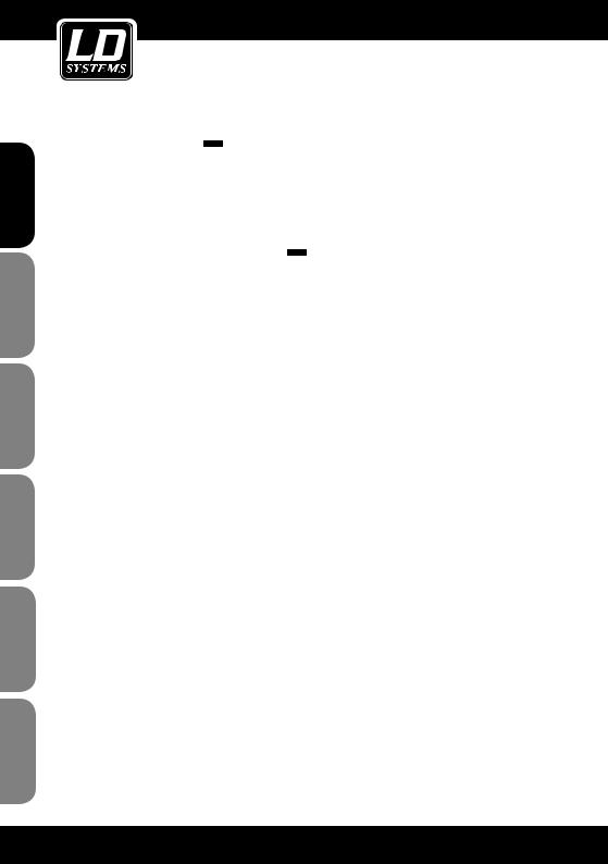
1MONO CHANNELS (MIC/LINE)
The mono channels offer balanced XLR connectors for low-impedance microphones and other low-level equipment. In addition, there are 6.3 mm TRS jack input connectors for microphones and line level equipment (e.g., synthesizers, drum computers, effects processors, etc.). Important: The MIC and LINE inputs cannot be used simultaneously on the same channel. +48V PHANTOM POWER The XLR inputs on the mono channels provide +48V phantom power for condenser microphones. Important: Never connect a microphone without phantom power to the XLR input when phantom power is on.
2INPUT GAIN ADJUSTMENT
The input gain control has two different scales: one for microphones and one for line level devices.The outer ring (0 ~ 44 dB) refers to microphones, the inner one (+15 ~ -30 dB) to line level devices.Always adjust the gain control so that the peak LED above the channel fader lights up only occasionally. If the LED is on constantly, this can lead to distortion.
3LOW CUT FILTER
The LOW CUT button activates a low cut filter (75 Hz, slope 18 dB/octave) for reducing low-frequency noise such as mains hum or handling noises from vocal microphones.
4STEREO CHANNELS
The stereo channels are configured as stereo pairs with 6.3 mm TRS jack input connectors. Mono signal sources should be connected to the left jack input connector.
5+4dBu/-10dBV SELECTOR
The line inputs of the stereo channels have a button for selecting the input sensitivity (+4 dBu for professional audio equipment, -10 dBV for general hi-fi devices, etc.). If you are uncertain which setting to use for the respectively connected device, first try +4 dBu. If the level is too low, switch to -10 dBv.
6AUX SENDS
These 6.3 mm TRS sockets can be used to split the signal and send it additionally to external effects processors or the like. In addition, these outputs can be used as submix outputs.
7PHONE
Headphones for monitoring the output signal (MAIN MIX) can be connected to this TRS socket.
1
2
3
4
5
6
7
MIC 1
BAL OR
UNBAL
LINE IN 1
+15dB -25dB LINE
0dB 40dB MIC
LOW CUT 75Hz 18dB/Oct
LINE IN 19/20
LEFT(MONO)
RIGHT
+4dBu  -10dBV
AUX SENDS
1
2
PHONE
ESPAÑOL FRANCAIS FRANCAISDEUTSCH FRANCAISENGLISH
ITALIANO POLSKI
7

FRNCAISITALIANO POLSKIFRANCAIS ESPAÑOL FRANCAIS DEUTSCH ENGLISH
CONTROL ELEMENTS:
EQUALIZER
The mono input channels of the LAX12D are equipped with 3-band equalizers (HI/MID/LOW; MID: with adjustable centre frequencies), the stereo channels with 4-band EQs with fixed centre frequencies (HI,
HI-MID, MID-LOW and LOW).The boost/cut range is +/-15 dB.
|
|
8 |
|
|
|
|
|
|
|
|
|
|
8 |
HI |
|
|
|
|
|
|
|
|
|
|
|
|
This knob is used to control the high frequencies. You can use it to |
|
|
|
|
|
|
|
|
|
|
|
|
|
|
|
|
|
|
|
|
|
|
|
|
|
add more brilliance and presence to the corresponding signal or |
|
|
|
|
|
|
|
|
|
|
|
|
|
|
|
|
|
|
|
|
|
|
|
|
|
attenuate undesirably loud high frequencies (boost/cut range -15 |
9 |
|
|
|
|
|
|
|
|
|
|
|
dB to +15 dB, centre frequency 12 kHz). |
|
|
|
|
|
|
|
|
|
|
|
9 |
|
|
|
|
|
|
|
|
|
|
|
|
|
|
|
|
|
|
|
|
|
|
|
||
MID |
|
|
|
|
|
|
|
|
|
|
|
|
|
|
|
|
|
|
|
|
|
|
|
||
|
This knob is used to control the midrange frequencies. These are |
|
|
|
|
|
|
|
|
|
|
|
|
the most important frequencies for musical instruments and the |
|
|
|
|
|
|
|
|
|
|
|
|
|
|
|
|
|
|
|
|
|
|
|
|
|
human voice (boost/cut range -15 dB to +15 dB).The FREQ knob |
|
|
|
|
|
|
|
|
|
|
|
|
is used to set the centre frequency that is to be boosted or cut |
|
|
|
|
|
|
|
|
|
|
|
10 |
(100 Hz to 8 kHz). |
13 |
|
|
|
|
|
|
|
|
|
|
|
|
|
|
|
|
|
|
|
|
|||
HI-MID |
|
|
|
|
|
|
|
|
|
|
||
|
This knob is used to control the hi-mids, which are slightly higher |
|
|
|
|
|
|
|
|
|
|
|
|
|
|
|
|
|
|
|
|
|
|
|
|
|
than the frequencies covered by the MID EQ. This provides even |
|
|
|
|
|
|
|
|
|
|
|
|
greater flexibility when it comes to equalization of the important |
|
|
|
|
|
|
|
|
|
|
|
|
midrange frequencies. |
|
|
|
|
|
|
|
|
|
|
|
11 |
MID-LOW |
|
|
|
|
|
|
|
|
|
|
|
|
This knob is used to control the mid-low frequencies (boost/cut |
15 |
|
|
|
|
|
|
|
|
|
|
|
range -15 dB to +15 dB, centre frequency 500 Hz). |
|
|
|
|
|
|
|
|
|
|
|
12 |
LOW |
16 |
|
|
|
|
|
|
|
|
|
|
|
|
|
|
|
|
|
|
|
|
|
||
|
This knob is used to control the low frequencies. You can use |
|
|
|
|
|
|
|
|
|
|
|
|
it, for example, to boost a bass drum, bass guitar or male voice |
|
|
|
|
|
|
|
|
|
|
|
|
|
|
|
|
|
|
|
|
|
|
|
|
13 |
(boost/cut range -15 dB to +15 dB, centre frequency 80 Hz). |
|
|
|
|
|
|
|
|
|
|
|
|
|
|
|
|
|
|
|
|
|
|
||
|
|
|
|
|
|
|
|
|
|
|
||
AUX SEND CONTROLS |
|
|
|
|
|
|
|
|
|
|
|
|
|
|
|
|
|
|
|
|
|
|
|
||
|
These two knobs are used to adjust the level of the signals sent |
|
|
|
|
|
|
|
|
|
|
|
|
|
|
|
|
|
|
|
|
|
|
|
|
|
|
|
|
|
|
|
|
|
|
|
|
|
|
to AUX buses 1 and 2. This does not affect the MAIN MIX output |
18 |
|
|
|
|
|
|
|
|
|
|
|
|
|
|
|
|
|
|
|
|
|
||
|
|
|
|
|
|
|
|
|
|
|
||
|
signal. AUX 1 can be configured as PRE or POST fader using the |
|
|
|
|
|
|
|
|
|
|
|
|
|
|
|
|
|
|
|
|
|
|
||
|
PRE/POST button. In the POST position (button not pressed) the |
|
|
|
|
|
|
|
|
|
|
|
|
|
|
|
|
|
|
|
|
|
|
|
|
|
|
|
|
|
|
|
|
|
|
|
|
|
|
signal is sent after the channel fader, meaning that the volume set |
|
|
|
|
|
|
|
|
|
|
|
|
|
|
|
|
|
|
|
|
|
|
|
|
|
for this channel also affects the AUX 1 signal. In the PRE position |
|
|
|
|
|
|
|
|
|
|
|
|
|
|
|
|
|
|
|
|
|
|
|
|
|
(button pressed), the signal is sent before the fader, so that the |
|
|
|
|
|
|
|
|
|
|
|
|
|
|
|
|
|
|
|
|
|
|
|
|
|
channel fader does not affect the AUX 1 signal.AUX 2 is a "post |
|
|
|
|
|
|
|
|
|
|
|
|
fader" path. |
|
|
|
|
|
|
|
|
|
|
|
10
11
12
14
17
PEAK |
|
PEAK |
||||
10 |
|
|
|
|
|
10 |
|
||||||
dB |
|
|
|
dB |
||
5 |
|
|
|
|
|
5 |
|
||||||
0 |
|
|
|
|
|
0 |
|
|
|
|
|||
-5 |
|
|
|
|
|
-5 |
|
||||||
-10 |
|
|
|
|
|
-10 |
|
|
|
|
|
||
|
|
|
|
|
||
|
|
|
||||
|
|
|
|
|
|
|
|
|
|
|
|
|
|
-15 |
|
|
|
|
-15 |
|
-20 |
|
|
|
|
|
-20 |
|
|
|
|
|
||
|
|
|
|
|
||
|
|
|
||||
-30 |
|
|
|
|
|
-30 |
|
|
|
|
|
||
|
|
|
|
|
||
|
|
|
||||
-40 |
|
|
|
|
|
-40 |
|
|
|
||||
-60 |
|
|
|
|
|
-60 |
|
|
|
||||
OO |
|
|
|
|
OO |
|
|
|
|
||||
8

CONTROL ELEMENTS:
14PAN/BAL
The mono channels of the LAX12D have panorama (PAN) controls and the stereo channels have balance
(BAL) controls, both of which are used to distribute the signal to the right and left output channels.
15MUTE/ALT3-4
Each of the channels of the LAX12D has a MUTE/ALT3-4 switch. This switch can be used to send the signal of the respective channel to the ALT3-4 output.
16SOLO
The SOLO switch lets you hear only the signal of the channel for which the solo function is activated (button pressed) without the other channels. The SOLO switch is especially useful for adjusting input levels (gain adjustment) and as a "preview" option for monitoring the respective signal.
17PEAK LED
All channels of the LAX12D are equipped with a peak LED for monitoring the respective audio signal. If the peak LED lights up (6 dB below the actual clipping threshold), this means that the signal is peaking and distortion may ensue.
18CHANNEL FADER
This fader controls the overall volume of the respective channel, i.e., the level at which the signal is sent to the main mix.
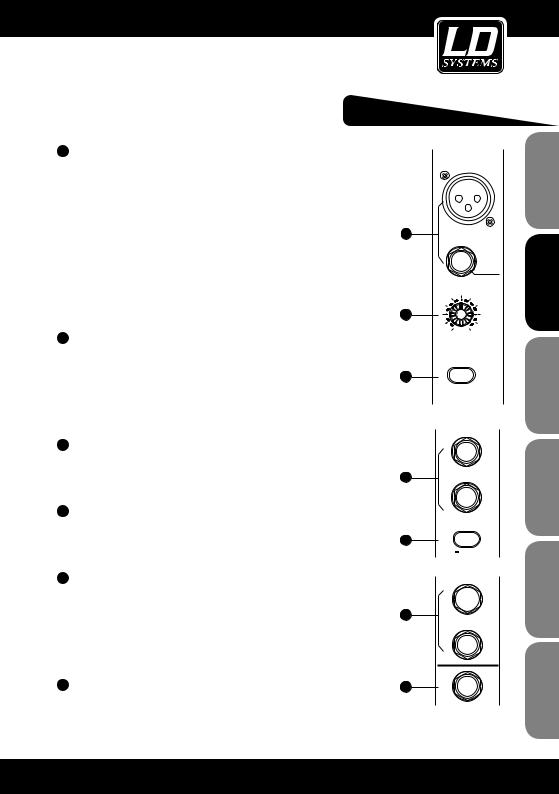
192-TRACK IN/OUT
TAPE IN: Use the TAPE IN input to connect a tape recorder or DAT recorder. Press the 2TK IN button on the front panel to send the signal coming from the connected device to the PHONES/CONTROL ROOM output or the 2TK TO MAIN MIX button to send it to the MAIN MIX output. TAPE OUT: The mix can be output to a tape recorder via these cinch (RCA) connectors. 2TK IN CONTROL: This control is used to adjust the level of the 2TK IN signal, which can be varied from ∞ to MAX.
ESPAÑOL FRANCAIS FRANCAISDEUTSCH FRANCAISENGLISH
ITALIANO POLSKI
9

FRNCAISITALIANO POLSKIFRANCAIS ESPAÑOL FRANCAIS DEUTSCH ENGLISH
CONTROL ELEMENTS:
20STEREO AUX RETURNS
These 6.3 mm jack (TRS) sockets are primarily used to return the audio signal from an external effects processer to the mixer (MAIN MIX). In addition, these connectors can be used as additional AUX inputs. Note: If no connector is plugged into Aux Return 2, the signal of the internal effects processor is present on Aux Return 2.
1 |
2 |
|
|
|
|
|
|
|
2TK IN |
|
|
|
L |
|
LEFT(MONO) |
LEFT |
|
|
|
|
|
|
R |
MAX |
|
|
|
|
|
RIGHT |
RIGHT |
TAPE IN |
TAPE OUT |
|
STEREO AUX RETURNS |
2-TRACK IN/OUT |
|
||
|
|
|
||
20 |
|
|
19 |
|
10
|
|
CONTROL ELEMENTS: |
FRANCAISENGLISH |
||||||
21 AUX RETURN CONTROL |
|
0 |
|
88 |
|
|
|
||
|
0 |
1 |
|
|
|
|
|
|
|
This control is used to adjust the return levels of AUX |
|
|
|
|
|
PROGRAM (PUSH) |
|
|
|
paths 1 & 2, whereby the signals are added to the L/R |
|
|
|
|
|
|
|
|
|
MAIN MIX. |
21 |
-8 |
+15 |
|
|
|
|
|
|
|
AUX RTN 1 |
|
|
|
|
|
|
||
|
|
|
|
|
|
|
|
||
22 EFX TO AUX 1 |
|
|
2 |
|
FUNCTION |
|
|
|
|
|
|
00-09 |
Echo |
50-59 Vocal |
|
|
|
||
This switch routes the signal that is present at AUX |
|
|
|
|
|
|
|||
|
|
|
20-29 |
Tremolo |
70-79 Small Room |
|
|
|
|
|
|
|
|
10-19 Echo +Verb |
60-69 Rotary |
|
|
|
|
RETURN 2 to the AUX 1 output so that the effects |
|
-8 |
+15 |
30-39 |
Plate |
80-89 Flange+Verb |
|
|
|
|
AUX RTN 2 |
DFX |
40-49 |
Chorus |
90-99 Large Hall |
|
|
|
|
can also be heard in the monitor mix - which proves |
22 |
|
|
-8 |
+15 |
|
|
|
FRANCAISDEUTSCH |
to +15 dB).This makes it possible to boost the AUX |
|
|
|
|
|
||||
extraordinarily helpful in practice. |
|
EFX TO AUX 1 |
PEAK/MUTE |
DFX MUTE |
|
|
|
||
23 AUX SEND CONTROLS |
|
|
|
|
0 |
|
|
|
|
|
|
|
|
|
|
|
33 |
|
|
These controls adjust the master AUX SEND level (-∞ |
|
|
|
|
|
|
|
|
|
signals by up to 15 dB if necessary. |
1 |
0 |
|
PHONES |
|
|
32 |
|
|
|
CONTROL ROOM |
CTR ROOM |
|
|
|
||||
|
|
|
|
|
|
SOURCE |
|
|
FRANCAIS |
24 LED LEVEL METER |
|
|
|
PHANTOM PWR |
|
|
|
||
|
-8 |
+15 |
+7 |
|
|
31 |
|||
The stereo level meter (12 segments) is used to |
23 |
0 |
|
|
|
MAIN MIX |
|
|
|
monitor the level of the output signal. |
2 |
|
|
|
|
|
|
|
|
|
|
|
CLIP |
|
|
30 |
|
||
|
|
|
|
+10 |
ALT 3-4 |
|
|
|
|
25 SOLO MODE BUTTON & SOLO LED [25] |
|
|
|
|
|
|
|
|
|
|
AUX SENDS |
+4 |
|
|
|
|
|||
These buttons are used to toggle between the |
|
|
|
|
|
||||
|
|
|
+2 |
|
|
|
|
||
two solo modes PFL (pre-fader listening, button |
|
|
|
|
0 |
2TK IN |
|
|
|
|
|
|
|
|
|
|
|
|
|
not pressed) and AFL (after-fader listening, button |
|
|
|
|
-2 |
ASSIGN |
|
|
ESPAÑOL |
In PFL mode, the signals of the channels that have |
24 |
|
LEVEL |
-30 |
TO MIX |
|
|
||
pressed). |
|
|
-4 |
|
|
|
|||
|
SET |
|
|
|
29 |
|
|||
|
|
|
|
|
-7 |
|
|
|
|
|
|
|
|
-10 |
ALT 3-4 |
|
|
|
|
|
|
SOLO |
|
-20 |
|
|
|
||
|
|
|
|
|
|
|
|||
|
|
ACTIVE |
|
|
|
|
|||
|
|
|
|
|
|
|
|
||
been switched to SOLO are sent pre fader, i.e., the fa- |
25 |
|
PFL |
L |
R |
|
|
28 |
|
|
AFL |
|
|
|
|
||||
der position (channel volume) does not influence the |
|
SOLO MODE |
OUTPUT LEVEL |
2TK |
|
|
|
||
|
|
|
|
|
|
|
|||
solo signal. In AFL mode, the signals of the channels |
|
|
|
|
|
LEVEL |
|
|
|
|
|
|
|
|
MAIN MIX |
|
|
|
|
that have been switched to SOLO are sent post fader |
|
|
10 |
|
|
10 |
10 |
|
|
plus panorama control – which, although it is above |
|
|
dB |
|
|
dB |
dB |
|
POLSKI |
|
|
|
-5 |
|
|
-5 |
-5 |
|
|
the channel fader, comes after the fader in terms of |
|
|
5 |
|
|
5 |
5 |
|
|
circuitry. In this mode, the position of the channel |
|
|
0 |
|
|
0 |
0 |
|
|
|
|
|
|
|
|
|
|
|
|
fader and the panorama control also influences the |
|
|
|
|
|
|
|
|
|
solo signal. Note: The SOLO mode selection (PFL/AFL) |
|
|
-10 |
|
|
-10 |
-10 |
|
|
does not have any affect until at least one channel |
|
|
-15 |
|
|
-15 |
-15 |
|
|
has been switched to solo mode. In this case, the |
26 |
|
-20 |
|
|
-20 |
-20 |
|
|
SOLO ACTIVE LED is also illuminated. |
|
|
|
|
ITALIANO |
||||
|
|
-30 |
|
|
-30 |
-30 |
|
||
|
|
|
|
|
|
||||
|
|
|
-40 |
|
|
-40 |
-40 |
|
|
26 ALT3-4 FADERS |
|
|
-60 |
|
|
-60 |
-60 |
27 |
|
|
|
|
|
|
|
|
|
||
These faders are used to control the level of the ALT |
|
|
ALT 3-4 |
|
LEFT |
RIGHT |
|
|
|
output (control range -∞ to +10 dB). |
|
|
|
|
|
|
|
|
|
|
|
|
|
|
|
|
|
|
11 |

CONTROL ELEMENTS:
FRNCAISITALIANO POLSKIFRANCAIS ESPAÑOL FRANCAIS DEUTSCH ENGLISH
27MAIN MIX LEVEL
These two faders are used to control the level of the signals sent to the L/R MAIN MIX and TAPE OUT outputs.
28TK TO MAIN MIX
When this button is pressed, the 2-TRACK IN signal is sent to the MAIN MIX output.
29ALT3-4 TO MAIN MIX
When this button is pressed, the ALT3-4 signal is sent to the MAIN MIX output and added to the output signal.
30CONTROL ROOM SOURCE
These buttons are used to determine which signal is heard via the monitor speakers or headphones: MAIN MIX, ALT 3-4, 2TK IN. Please note that these buttons are inactive in solo mode. If the selected signal cannot be heard after the CONTROL ROOM SOURCE buttons are pushed, please first check whether the solo mode has been activated in one of the channels.
31PWR LED (POWER)
This LED indicates that the mixer is on.
32PHANTOM LED
This LED indicates that phantom power has been activated.
33PHONE/CONTROL ROOM
This control is used to adjust the level of the signal sent to the PHONE/CONTROL ROOM output.
12
CONTROL ELEMENTS:
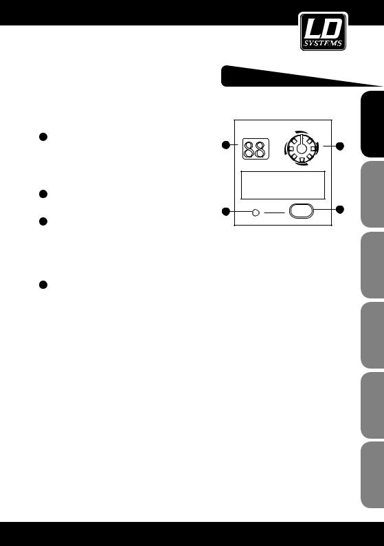
DIGITAL 24-BIT EFFECTS PROCESSOR
|
|
|
|
PROGRAM (PUSH) |
34 DFX MUTE SWITCH |
35 |
88 |
36 |
|
This switch is used to activate/deactivate the effects |
||||
module. If necessary, this function can also be controlled |
|
|
||
conveniently using a footswitch connected to the FOOT |
|
|
FUNCTION |
|
SW socket. |
|
00-09 |
Echo |
50-59 Vocal |
|
|
10-19 |
Echo +Verb |
60-69 Rotary |
|
|
20-29 |
Tremolo |
70-79 Small Room |
35 DISPLAY |
|
30-39 |
Plate |
80-89 Flange+Verb |
|
40-49 |
Chorus |
90-99 Large Hall |
|
|
|
|||
The selected preset is displayed here. |
37 |
|
|
34 |
|
|
|
||
|
|
|
|
|
36 PRESET SELECTOR |
|
PEAK/MUTE |
DFX MUTE |
|
|
|
|
||
This knob is used to select the desired effects preset. There is a total of 100 presets available: Echo, vocal, plate and versatile two-effect combinations. Once you have selected the desired preset, press the knob to confirm your selection.
37PEAK LED
This LED lights up when the input signal reaches the clipping threshold. When the digital effects module is deactivated, this LED is illuminated constantly.
ESPAÑOL FRANCAIS FRANCAISDEUTSCH FRANCAISENGLISH
ITALIANO POLSKI
13

FRNCAISITALIANO POLSKIFRANCAIS ESPAÑOL FRANCAIS DEUTSCH ENGLISH
BACK PANEL:
44 |
42 |
PHANTOM |
ON OF
POWER
43
Apparaten skall anslutas till jordat uttag nar den ansluts till ett natverk
|
|
|
|
|
FOOT SW |
RIGHT |
LEFT |
|
|
|
|
|
|
|
|
|
|
|
|
|
|
|
|
|
|
|
|
|
|
|
|
|
|
|
|
|
|
|
|
MAIN MIX OUTPUT(BAL/UNBAL)
AC INPUT |
EUROPE |
210-240V£50Hz |
Fuse:T250mAL |
RATED POWER CONSUMPTION: 23W
45 |
41 |
DO NOT OPEN |
|
CAUTION: |
|
CAUTION |
|
|
|
RISK OF ELECTRIC SHOCK |
|
|
|
WARNING: SHOCK HAZARD - DO NOT OPEN |
REPLACE WITH THE SAME TYPE FUSE AND RATING |
||
DISCONNECT SUPPLY CORD BEFORE CHANGING FUSE |
|||
AVIS: RISQUE DE CHOC ELECTRIQUE - NE PAS OUVRIR |
|
||
L |
|
|
|
|
LEFT(3) |
4 |
3 |
R |
|
INSERT |
INSERT |
|
|
|
|
OUTPUT |
RIGHT(4) |
|
|
CTRL ROOM |
ALT OUTPUT |
|
|
40 |
39 |
|
38 |
|
MODEL |
|
SERIAL |
2 |
1 |
INSERT |
INSERT |
38INSERTS (MONO CHANNELS)
All mono MIC channels are additionally equipped with Insert sockets (stereo jack, TRS), via which external effects devices or the like can be patched into the respective channel. The signal is sent immediately after the input gain control (TRIM) to an external signal processor, for example, a compressor or limiter. Once the signal has passed through the external signal processor, it is returned to the same channel immediately before the EQ. Note: Connecting external devices to insert points requires a so-called "Y" cable.
39CTRL ROOM OUTPUT
These 6.3 mm sockets are used to send the signal to studio monitor speakers (CONTROL ROOM) or a PA system.
40ALT OUTPUT
These unbalanced 6.3 mm sockets serve as additional outputs. Their level is controlled using the ALT 3-4 fader in the master section of the mixer (max. +22 dBu).The signals of all channels for which the Mute/Alt 3-4 button has been pushed are routed to this bus; they no longer reach the main mix.
41MAIN MIX OUTPUT
The L/R MAIN MIX OUTPUT has both XLR and 6.3 mm TRS sockets via which the main mix output signal can be sent to an amplifier.The output level is controlled by the MAIN MIX LEVEL fader (-∞ to +10 dB).
42FOOT SW
This socket can be used to connect an external footswitch for activation/deactivation of the integral effects processor (function identical with that of the DFX MUTE switch).
43PHANTOM SWITCH
This switch activates the +48V phantom power for the four XLR microphone inputs. Important: Make certain that the phantom power is off before connecting microphones.
44POWER SWITCH
This switch is used to turn the mixer ON or OFF.
45AC INPUT
This socket is used to connect the power adapter.
14

INSTALLATION AND CONNECTION:
INSTALLATION AND CONNECTION
Now that you have familiarized yourself with the functions of the LAX12D mixer, you should have no trouble using it. Nevertheless, we recommend that you read the following section carefully. It contains important information about how to obtain the best results with your mixer.
-Before connecting mics or instruments, make certain that the channel and MAIN MIX faders of the LAX12D mixer are set to minimum (all the way down).
-Make certain that all external devices such as mics, power amplifiers, speakers, effects processors, etc. are connected properly.
-When running cables, take care not to injure anyone or damage the equipment.
-Set the output level of your mixer and the connected power amplifier to no more than 75%.
-Do not set the PHONE/CONTROL ROOM level higher than 50%.
-Set the EQ controls (HI, MID, LOW) to the middle position.
-Set the PAN/BAL controls to the middle position.
-While speaking into each connected mic (speech or vocals) or playing the instrument, adjust each channel fader (LEVEL) so that the peak LED of the corresponding channel comes on only occasionally. This will ensure that there is always enough headroom and dynamic range available.
-You can shape the sound of the individual signals using the respective channel equalizer.
-Repeat this sequence of steps for all of the input channels being used, always keeping an eye on the LED level meter (OUTPUT LEVEL) so that it does not swing too far into the red area.
AUDIO CONNECTIONS
The LAX12D mixer offers numerous, highly flexible possibilities for balanced or unbalanced connection of your equipment via XLR and 6.3 mm TRS connectors. These are explained below.
WIRING CONFIGURATION
The XLR and 6.3 mm TRS connectors of the LAX12D permit balanced and unbalanced connections depending on the equipment connected. Examples for wiring your system:
ESPAÑOL FRANCAIS FRANCAISDEUTSCH FRANCAISENGLISH
ITALIANO POLSKI
15

FRANCAIS DEUTSCH ENGLISH
WIRING CONFIGURATION:
UNBALANCED |
BALANCED |
UNBALANCED |
||
+ |
|
+ |
|
+ |
FOR 6.3 MM |
|
- |
|
|
|
|
|
|
|
TRS PLUGS |
|
|
|
|
Tip |
Ring |
Tip |
Ring |
Tip |
Sleeve |
|
Sleeve |
|
Sleeve |
FOR XLR |
UNBALANCED |
|
BALANCED |
|
|
|
|
CONNECTORS |
Pin2 (+) |
Pin3 (-) |
Pin2 (+) |
|
|
||
|
Pin3 (-) |
|
|
|
|
|
|
|
(Linked to Pin1 manually, |
) |
|
Pin1 ( |
) |
|
Pin1 ( ) |
IN-LINE CONNECTION |
|
|
|
The mixer provides 6.3 mm stereo and XLR connectors for in-line connection of most professional audio equipment. Configuration examples for the respective connections are provided below.
FRNCAISITALIANO POLSKIFRANCAIS ESPAÑOL
BALANCED
UNBALANCED
TIP RING SLEEVE
1 3
3 2
2
TIP RING SLEEVE
TIP RING SLEEVE
TIP SLEEVE
2 1 3
3
TIP SLEEVE
TIP RING SLEEVE
TIP SLEEVE
TIP RING SLEEVE
2 1 3
3
|
Tip |
|
SLEEVE RING TIP |
Ring |
|
Sleeve |
||
|
||
1 3 |
1 |
|
2 |
2 |
|
|
3 |
|
1 |
Tip |
|
3 |
Ring |
|
2 |
|
|
|
Sleeve |
|
1 |
Tip |
|
2 |
Ring |
|
3 |
|
|
|
Sleeve |
|
|
Tip |
|
1 |
|
|
3 |
Sleeve |
|
2 |
||
|
1 |
|
|
2 |
|
|
3 |
|
|
Tip |
|
SLEEVE TIP |
Sleeve |
|
|
Tip |
|
|
Ring |
|
SLEEVE RING TIP |
Sleeve |
|
|
Tip |
|
|
Sleeve |
|
|
Tip |
|
|
Ring |
|
|
Sleeve |
|
|
1 |
|
3 |
2 |
|
1 |
3 |
|
2 |
Tip
Ring
Sleeve
1
2
3
1
2
3
1
2
3
1
2
3
Centre
Screen
Tip
Sleeve
Tip
Ring
Sleeve
Centre
Screen
Centre
Screen
1
2
3
16

WIRING CONFIGURATION / PRESET LIST:
INSERT CONNECTION
When connecting external signal processors via the main insert on the mixer, one TRS cable is required for each send/return. The configuration of this so-called "Y" cable is depicted below.
FOR 6.3 MM STEREO PLUGS (TRS INSERT)
INSERT CABLE
Send
Return
Ring |
Tip |
|
Sleeve
TIP RING SLEEVE
TIP RING SLEEVE
TIP RING SLEEVE
SLEEVE TIP
SLEEVE RING TIP
1
3
2
2 3 1
Tip |
Tip (Send) |
||
Sleeve |
|||
Ring |
|||
Sleeve |
Tip (Return) |
||
|
Sleeve |
||
|
1 |
|
|
Tip |
2 |
(Send) |
|
3 |
|
||
Ring |
1 |
|
|
Sleeve |
|
||
2 |
(Return) |
||
|
|||
|
3 |
|
|
Tip |
Centre (Send) |
||
Screen |
|||
Ring |
|||
Sleeve |
Centre (Return) |
||
|
Screen |
||
NO. |
PRESET |
DESCRIPTION |
PARAMETER |
|
|
|
|
00-09 |
Echo |
The input signal is sent to the output with a time delay |
Delay time: 145 - 205 ms |
|
|
|
|
10-19 |
Echo+Verb |
Echo with room effect (hall) |
Delay time: 208 - 650 ms |
|
|
|
Decay time: 1.7 - 2.1 s |
|
|
|
|
20-29 |
Tremolo |
Amplitude modulation of the signal |
Rate: 0.6 Hz - 5 Hz |
|
|
|
|
30-39 |
Plate |
Hall effect: Simulation of the classic plate vocal effect |
Decay time: 0.9 s ~ 3.6 s |
|
|
(adds brightness) |
|
|
|
|
|
40-49 |
Chorus |
Creates the illusion of multiple instruments (voices) on the basis of a |
Rate: 0.92 Hz ~ 1.72 Hz |
|
|
single signal |
|
|
|
|
|
50-59 |
Vocal |
Hall effect: Simulation of a small room with a short decay time |
Rev. decay time: 0.8 ~ 0.9 s |
|
|
|
Pre-delay: 0 - 45 ms |
|
|
|
|
60-69 |
Rotary |
Simulation of typical rotary speaker effect incl. bass box |
Modulation depth : |
|
|
|
20% ~ 80% |
|
|
|
|
70-79 |
Small room |
Hall effect: Simulation of a bright studio room effect |
Decay time: 0.7 ~ 2.1 s |
|
|
|
Pre-delay : 20 - 45 ms |
|
|
|
|
80-89 |
Flanger + Verb |
Combination of a modulated delay effect plus hall |
Decay time: 1.5 ~ 2.9 s |
|
|
|
Rate : 0.8 Hz ~ 2.52 Hz |
|
|
|
|
90-99 |
Large hall |
Hall effect: Simulation of a large room |
Pre-delay : 23 ~ 55 ms |
|
|
|
|
ESPAÑOL FRANCAIS FRANCAISDEUTSCH FRANCAISENGLISH
ITALIANO POLSKI
17

FRNCAISITALIANO POLSKIFRANCAIS ESPAÑOL FRANCAIS DEUTSCH ENGLISH
SPECIFICATIONS:
MONO CHANNELS
Microphone input: electronically balanced, separate inputs
Frequency range: 10 Hz … 45 kHz, +/-3 dB THD+N: 0.005% @ +4 dBu, 1 kHz
Gain: 0 dB … 40 dB (MIC) Signal-to-noise ratio: 102 dB
Line input: electronically balanced Frequency range: 10 Hz … 45 kHz, +/-3 dB THD+N: 0.005% @ +4 dBu, 1 kHz
Gain: +15 dBu … -25 dBu (LINE)
STEREO CHANNELS
Line input: unbalanced
Frequency range: 10 Hz … 45 kHz, +/-3 dB THD+N: 0.005% @ +4 dBu, 1 kHz
IMPEDANCE
Microphone input: 3.6 kohm
All other inputs: 10 kohms or higher
Tape out: 1 kohm
All other outputs: 120 ohms
EQUALIZER
Treble (shelving):+/-15 dB @ 12 kHz
Midrange (bell, mono channels): +/-15 dB @ 100 Hz … 8 kHz
High midrange (stereo channels): +/-15 dB @ 3 kHz Low midrange (stereo channels): +/-15 dB @ 500 Hz Bass (shelving): +/-15 dB @ 80 Hz
Low cut filter: 75 Hz, 18 dB/oct.
DSP EFFECTS SECTION
A/D and D/A converters: 24-bit DSP resolution: 24-bit
Effect types: Echo, echo+ reverb, tremolo, plate, chorus, vocal, rotary, small room, flanger + reverb, large hall No. of presets: 100
Switches: Preset selector switch, effect bypass
MAIN MIX SECTION
Noise (bus noise): Fader 0 dB, channels muted: -100 dBr (ref.: +4 dBu)
Fader 0 dB, all input channels activated (unity gain): -90 dBr (ref.: +4 dBu)
Max output level: +22 dBu (XLR, balanced); +22 dBu (6.3-mm jack, unbalanced)
AUX returns, gain: OFF … +15 dB AUX sends, max. output level: +22 dBu
POWER SUPPLY
(AC adapter) Mains voltage:
USA/Canada 100 – 120 V, ~60 Hz Europe 210 – 230 V, ~50 Hz
Great Britain/Australia 240 V, ~50 Hz
Power consumption: 12-channel mixer: 30 W
PHYSICAL SPECIFICATIONS
Dimensions (WxDxH):
12-channel mixer: 315 x 436 x 86 mm Weight:
12-channel mixer: 5.1 kg without adapter
Subject to technical modifications without prior notice, because all of our products are tested and improved continually.
18

USB PORT |
MP3 PLAYER: |
For USB memory sticks only |
POWER 
To power on the USB-MP3 player keep the power button pressed for 3 seconds. Same procedure to power it off. Once the player is on, it is automatically set to the "pause" mode.
PLAY / PAUSE 

Press this button during playback to pause the playback. Press again to start the playback again.
STOP 
Press this button during playback to stop the playback. The display will now show how many tracks are available on the USB memory stick. When the playback has been stopped press PRE/NEXT to go the previous/next track or press the STOP button again to go to the beginning of the first track. Press the PLAY/PAUSE button to start the playback again.
PRE 

Pressing this button while in pause mode will take you to the previous track. The pause mode remains ON. Press the PLAY/PAUSE button to start the playback again. Pressing this button during playback will take you to the previous track and play it.
NEXT 

Pressing this button while on pause mode will take you to the next track. The pause mode remains ON. Press the PLAY/PAUSE button to start the playback again. Pressing this button during playback will take you to the next track and play it.
REPEAT 


Press this button to choose between the four following repeat modes:
1. REP ALL 


Repeat all tracks available on the memory stick. Display shows:
|
|
|
MUSIC |
PLAY ER |
||
2. REP 1 |
||||||
|
|
|
||||
Repeat one track. Display shows |
|
|
|
|||
|
|
|
|
|||
3. PLAY IN ORDER |
|
|
||||
Plays the tracks selected previously. No display indication |
|
|
||||
4. RANDOM PLAY |
|
A |
||||
Plays all tracks in a random order. Display shows: A |
|
|||||
IMPORTANT: |
|
B |
||||
A Display when no USB memory stick is connected: |
|
|||||
|
|
|||||
B Display when the player scans your USB memory stick for MP3 music files: |
|
|
||||
C Display when the player is in pause mode: |
|
C |
||||
D Display when the player is on: |
|
|||||
|
|
|||||
|
|
|
|
|
D |
|
ESPAÑOL FRANCAIS FRANCAISDEUTSCH FRANCAISENGLISH
ITALIANO POLSKI
19

FRNCAISITALIANO POLSKIFRANCAIS ESPAÑOL FRANCAIS DEUTSCH ENGLISH
MANUFACTURER´S DECLARATIONS:
LIMITED WARRANTY
This Limited Warranty applies to the Adam Hall, LD Systems, Defender, Palmer and Eminence branded products.
The statutory warranty rights towards the seller are not affected by this guarantee. In fact, it justifies, additional independent warranty claims towards Adam Hall.
Adam Hall warrants that the Adam Hall product you have purchased from Adam Hall or from an Adam Hall authorized reseller is free from defects in materials or workmanship under normal use for a period of 2 or 5 years from the date of purchase.
The Limited Warranty Period starts on the date of purchase. In order to receive warranty services you are required to provide proof of the purchase date. Your dated sales or delivery receipt, showing the date of purchase, is your proof of the purchase date. Should products of the brands named above be in need of repair within the limited warranty period, you are entitled to warranty services according to the terms and conditions stated in this document.
This Limited Warranty extends only to the original purchaser of this Adam Hall branded product and is not transferable to anyone who obtains ownership of the Adam Hall branded product from the original purchaser. During the Limited Warranty Period, Adam Hall will repair or replace the defective component parts or the product. All component parts or hardware products removed under this Limited Warranty become the property of Adam Hall.
In the unlikely event that your Adam Hall product has a recurring failure, Adam Hall, at its discretion, may elect to provide you with a replacement unit of Adam Hall´s choice that is at least equivalent to your Adam Hall branded product in hardware performance.
Adam Hall does not warrant that the operation of this product will be uninterrupted or error-free. Adam Hall is not responsible for damage that occurs as a result of your failure to follow the instructions included with the Adam Hall branded product.
This Limited Warranty does not apply,
-to wear parts (e.g. accumulator)
-to any product from which the serial number has been removed or that has been damaged or rendered defec tive as the result of an accident
-in case of, misuse, abuse, or other external causes
-by operation outside the usage parameters stated in the user´s documentation shipped with the product
-by use of spare parts not manufactured or sold by Adam Hall
-by modification or service by anyone other than Adam Hall
These terms and conditions constitute the complete and exclusive warranty agreement between you and Adam Hall regarding the Adam Hall branded product you have purchased.
20
LIMITATION OF LIABILITY
If your Adam Hall branded hardware product fails to work as warranted above, your sole and exclusive remedy shall be repair or replacement. Adam Halls’ maximum liability under this limited warranty is expressly limited to the lesser of the price you have paid for the product or the cost of repair or replacement of any hardware components that malfunction in conditions of normal use.
Adam Hall is not liable for any damages caused by the product or the failure of the product, including any lost profits or savings or special, incidental, or consequential damages. Adam Hall is not liable for any claim made by a third party or made by you for a third party.
This limitation of liability applies whether damages are sought, or claims are made, under this Limited Warranty or as a tort claim (including negligence and strict product liability), a contract claim, or any other claim. This limitation of liability cannot be waived or amended by any person. This limitation of liability will be effective even if you have advised Adam Hall of an authorized representative of Adam Hall of the possibility of any such damages. This limitation of liability however, will not apply to claims for personal injury.
This Limited Warranty gives you specific legal rights. You may also have other rights that may vary from state to state or from country to country. You are advised to consult applicable state or country laws for a full determination of your rights.
REQUESTING WARRANTY-SERVICE
To request warranty service for the product, contact Adam Hall or the Adam Hall authorized reseller from which you purchased the product.
EG-DECLARATION OF CONFIRMITY
These products meet the essential requirements as well as the further standards of the EU Directives 199/5/EU, 89/336/EU.
CORRECT DISPOSAL OF THIS PRODUCT (ELECTRICAL WASTE) 
(Applicable in the European Union and other European countries with separate collection systems)
This marking shown on the product or its literature, indicates that it should not be disposed with other household wastes at the end of its working life. To prevent possible harm to the environment or human health from uncontrolled waste disposal, please separate this from other types of wastes and recycle it responsibly to promote the sustainable reuse of material resources.
Household users should contact either the retailer where they purchased this product, or their local government office, for details on where and how they can recycle this item in an enviromentally friendly manner.
Business users should contact their supplier and check the terms and conditions of the purchase contract. This product should not be mixed with other commercial wastes for disposal
ESPAÑOL FRANCAIS FRANCAISDEUTSCH FRANCAISENGLISH
ITALIANO POLSKI
21
FRNCAISITALIANO POLSKIFRANCAIS ESPAÑOL FRANCAIS DEUTSCH ENGLISH
WEEE-DECLARATION 
Your LD-Systems product was developed and manufactured with high quality materials and components wich can be recycled and/or reused. This symbol indicates that electrical and electronic equipment must be disposed of separately from normal waste at the end of its operational lifetime.
Please dispose of this product by bringing it to your local collection point or recycling centre for such equipment. This will help to protect the environment in which we all live.
BATTERIES AND ACCUMULATORS 
The supplied batteries or rechargeable batteries can be recycled. Please dispose of them as special waste or return them to your specialist dealer. In order to protect the environment, only dispose exhausted batteries.
Adam Hall GmbH, all rights reserved. The technical data and the functional product characteristics can be subject to modifications. The photocopying, the translation, and all other forms of copying of fragments or of the integrality of this user’s manual is prohibited.
22

NOTES:
ESPAÑOL FRANCAIS FRANCAISDEUTSCH FRANCAISENGLISH
ITALIANO POLSKI
23

FRNCAISITALIANO POLSKIFRANCAIS ESPAÑOL FRANCAIS DEUTSCH ENGLISH
Sie haben die richtige Wahl getroffen!
Diese LD-Systems Produkte werden Sie lange Jahre durch Zuverlässigkeit, Wirtschaftlichkeit und einfaches Handling überzeugen. Dafür garantiert LD-Systems mit seinem Namen und seiner in vielen Jahren erworbenen Kompetenz als Hersteller hochwertiger Geräte.
Nehmen Sie sich nun ein paar Minuten Zeit, diese Anleitung zu lesen. Wir möchten, dass Sie einfach und schnell in den Genuss dieser Technik kommen.
Mehr Informationen zu LD-SYSTEMS finden Sie auf unserer Internetseite WWW.LD-SYSTEMS.COM
24

LD LAX12D USB
12 CHANNEL MIXER WITH DSP & USB MP3 PLAYER
USB
MUSIC PLAYER
MIXING CON |
SOLE |
|
EQ
EQ
EQ
EQ
EQ
EQ
EQ
EQ
R
L
R
L
R
L
R
L
R
L
R
L
R
L
R
L
ESPAÑOL FRANCAIS FRANCAISDEUTSCH FRANCAISENGLISH
ITALIANO POLSKI
25

FRNCAISITALIANO POLSKIFRANCAIS ESPAÑOL FRANCAIS DEUTSCH ENGLISH
VORSICHTSMASSNAHMEN:
1.Bitte beachten Sie die Sicherheitshinweise und studieren Sie diese Anleitung sorgfältig.
2.Bewahren Sie alle Hinweise und Anleitungen sicher auf.
3.Verwenden Sie das Gerät nur in der vorgesehenen Art und Weise.
4.Beachten Sie die in Ihrem Land geltenden Entsorgungsgesetze.Trennen Sie bei der Entsorgung bitte Plastik und Papier bzw. Kartonagen von einander.
5.Sollte Ihr Gerät nicht mehr ordnungsgemäß funktionieren, Flüssigkeiten ausgesetzt worden oder auf sonstige Art und Weise beschädigt sein, überlassen Sie bitte jegliche Reparaturen ausschließlich autorisiertem Fachpersonal.
6.Halten Sie das Gerät von Hitzequellen wie z.B. Ofen, Heizkörper, oder sonstige Quellen (auch Verstärker) fern.
Sorgen Sie dafür dass das Gerät immer so installiert ist, dass es ausreichend gekühlt wird und nicht überhitzt.
7.Überprüfen Sie alle Verbindungen nach dem Sie das Gerät angeschlossen haben, um Schäden oder Unfälle zu vermeiden.
8.Verwenden Sie ausschließlich stabile und passende Stative bzw. Befestigungen, wenn das Gerät fest installiert wird. Stellen Sie sicher, dass das Gerät sicher installiert ist und nicht herunterfallen kann.
CAUTION |
RISK OF ELECTRIC SHOCK |
DO NOT OPEN |
ACHTUNG:
Entfernen Sie niemals die Abdeckung, da sonst die Gefahr eines elektrischen Schocks besteht.
Im Inneren des Gerätes befinden sich keine Teile, die vom Bediener gewartet oder repariert werden können.
Lassen Sie Reparaturen ausschließlich von qualifiziertem Servicepersonal durchführen.
Dieses Symbol warnt vor nichtisolierten, gefährlichen Spannungen im Geräteinneren, die einen gefährlichen Schlag verursachen können.
Dieses Symbol kennzeichnet wichtige Bedienungsund Wartungshinweise.
Vorsicht! Hohe Lautstärke!
Diese Übertragungsanlage wird von Ihnen professionell eingesetzt. Daher unterliegt der Gebrauch bei gewerblicher Nutzung den Regeln und Vorschriften der zuständigen Berufsgenossenschaft.Adam Hall als Hersteller ist daher verpflichtet, Sie auf möglicherweise bestehende gesundheitliche Risiken ausdrücklich hinzuweisen.
26

FUNKTIONEN & ERSTE SCHRITTE:
EINFÜHRUNG
Wir freuen uns, dass Sie sich für ein Audioprodukt von LD Systems entschieden haben.
Der Mixer LAX12DUSB ist ein Kompaktmischer für den professionellen Einsatz, mit angenehmem, natürlichem Klang und präziser Wiedergabe – ideal für Live-Auftritte,Aufnahmen und als festinstallierter PA-Mischer. Dabei bietet der LAX12DUSB einige Features, die in dieser Preisklasse nicht selbstverständlich sind.
Die Mono-Kanalzüge zeichnen sich durch außerordentlich rauscharme Mikrofon-Preamps mit +48VoltPhantomspeisung aus. Darüber hinaus sind alle Kanalzüge mit warm und natürlich klingenden Equalizern ausgestattet: die Mono-Kanalzüge mit 3-Band-EQs (MID: mit regelbaren Mittenfrequenzen) die Stereo-Kanalzüge mit 4-Band-EQs mit festen Mittenfrequenzen.Außerdem verfügt der LAX12DUSB über eine hochpräzise Aussteuerungsanzeige (12 Segmente), 2-Track-Eingänge, die sowohl auf die Summenausgänge als auch auf die Kopfhörer/Regie-Ausgänge geroutet werden können, und vieles mehr.
Zusätzlich stellt der integrierte 24-Bit-Effektprozessor 100 Effekt-Presets bereit.
Der LAX12DUSB-Mixer ist außerordentlich einfach zu bedienen. Dennoch empfehlen wir, diese Anleitung vor
Inbetriebnahme sorgfältig zu lesen, damit Sie wirklich das Optimum aus Ihrem Mixer herausholen.
FEATURES
Der LAX12DUSB-Mixer wurde für den professionellen Einsatz entwickelt und bietet folgende Ausstattung:
•Mikrofonkanäle mit vergoldeten XLR-Anschlüssen und symmetrischen Line-Eingängen
•Stereo-Kanalzüge mit symmetrischen Klinkeneingängen (TRS)
•Rauscharme, diskrete Mikrofon-Preamps mit +48-Volt-Phantomspeisung
•Hohe Aussteuerungsreserve und Dynamik
•Mono-Kanalzüge mit Inserts
•Schaltbare Trittschallfi lter in allen Mono-Kanalzügen
•+4dBu/-10dBV-Umschaltung in allen Stereo-Kanalzügen
•Warm und natürlich klingende 4-Band-Equalizer (feste Mittenfrequenzen) in den Stereo-Kanalzügen
•3-Band-Equalizer (MID: regelbare Mittenfrequenz, 100 Hz – 8 kHz) in den Mono-Kanalzügen
•Peak-LEDs in allen Kanalzügen
•Mute/Alt3-4/Solo-Funktion in allen Kanalzügen
•2 AUX-Returns als zusätzliche Eingänge
•Regieund Kopfhörer-Ausgänge
•2-Track-Eingänge mit Routing-Möglichkeiten auf Summen-, Regieund Kopfhörer-Ausgänge
•Hochpräzise Aussteuerungsanzeige (12 Segmente)
•Integrierter digitaler 24-Bit-Effektprozessor
•100 Effekt-Presets
•Effekt-Bypass-Funktion über MUTE-Taste oder Fußschalter (optional erhältlich,Anschluss an DFX FOOTS- WITCH-Buchse)
ESPAÑOL FRANCAIS FRANCAISDEUTSCH FRANCAISENGLISH
ITALIANO POLSKI
27

FRNCAISITALIANO POLSKIFRANCAIS ESPAÑOL FRANCAIS DEUTSCH ENGLISH
FUNKTIONEN & ERSTE SCHRITTE:
•Überprüfen Sie vor Anschluss Ihres LAX12DUSB-Mixers, dass die Stromversorgung mit der für das Gerät geeigneten
Netzspannung erfolgt.
•Vergewissern Sie sich, dass der Mixer ausgeschaltet ist, bevor Sie ihn an das Stromnetz anschließen, und stellen Sie alle Regler in “Null”-Stellung. Auf diese Weise vermeiden Sie Schäden an Ihren Lautsprechern durch laute Einschaltgeräusche und hohe Pegel.
•Schalten Sie immer zuerst den Mixer und danach den angeschlossenen Leistungsverstärker ein.´Beim Ausschalten gilt die umgekehrte Reihenfolge: Schalten Sie zuerst den Leistungsverstärker und danach den Mixer aus.
•Schalten Sie den LAX12DUSB-Mixer stets aus, bevor Sie Verkabelungen vornehmen.
•Verwenden Sie zur Reinigung des LAX12DUSB keine Lösungsmittel, sondern ein sauberes, trockenes Tuch.
ein. Beim Ausschalten gilt die umgekehrte Reihenfolge: Schalten Sie zuerst den Leistungsverstärker und danach den
Mixer aus.
•Schalten Sie den LAX12DUSB-Mixer stets aus, bevor Sie Verkabelungen vornehmen.
•Verwenden Sie zur Reinigung des LAX12DUSB keine Lösungsmittel, sondern ein sauberes, trockenes Tuch.
28
BEDIENELEMENTE:
1DIE MONOKANÄLE (MIC/LINE)
Die Mono-Kanalzüge bieten symmetrische XLR-Anschlüsse für niederohmige Mikrofone und anderes Equipment mit niedrigem Pegel.
Zusätzlich stehen 6,3-mm-Klinkeneingänge für den Anschluss von Mikrofonen und Geräten mit Line-Pegel (z.B. Synthesizer, Drum-Computer, Effektprozessoren etc.) zur Verfügung.
Achtung: Es ist nicht möglich, MICund LINE-Eingänge desselben Kanals gleichzeitig zu belegen.
+48-VOLT-PHANTOMSPEISUNG
Die XLR-Eingänge der Mono-Kanalzüge stellen +48-Volt-Phantomspannung zur Speisung von Kondensatormikrofonen bereit. Achtung:
Schließen Sie bei eingeschalteter Phantomspeisung niemals Mikrofone ohne Phantomspeisung an die XLR-Eingänge an.
2EINSTELLEN DER EINGANGSVERSTÄRKUNG
Der Gain-Regler verfügt über zwei unterschiedliche Einteilungen: eine für
Mikrofone und eine für Geräte mit Line-Pegel. Der äußere Ring (0 ~ 44 dB) bezieht sich auf Mikrofone, der innere (+15 ~ -30 dB) auf Geräte mit Line-
Pegel. Stellen Sie den Gain-Regler stets so ein, dass die Peak-LED oberhalb des Kanal-Faders nur gelegentlich aufleuchtet. Leuchtet die LED konstant, kann dies zu Verzerrungen führen.
3TRITTSCHALLFILTER (LOW CUT)
Die LOW CUT-Taste aktiviert ein Trittschallfi lter (75 Hz, Flankensteilheit 18 dB/
Oktave) zur Reduzierung von tieffrequenten Störgeräuschen wie Netzbrummen oder Handgeräusche von Vokalmikrofonen.
4DIE STEREOKANÄLE
Die Stereo-Kanalzüge sind jeweils als Stereopaare mit 6,3-mm-Klinkeneingängen (TRS) ausgeführt. Mono-Signalquellen schließen Sie an den linken Klinkeneingang an.
5+4dBu/-10dBV-UMSCHALTUNG
Die Line-Eingänge der Stereo-Kanalzüge verfügen über eine Taste zur
Umschaltung der Eingangsempfi ndlichkeit (+4 dBu für professionelles AudioEquipment, -10 dBV für HiFi-Geräte etc.). Falls Sie nicht sicher sind, welche
Einstellung für das jeweils angeschlossene Gerät geeignet ist, versuchen Sie es zuerst mit +4 dBu. Sollte der Pegel nicht hoch genug sein, schalten Sie auf -10 dBV um.
6AUX SENDS
Über diese 6,3-mm-Klinkenbuchsen kann das Signal gesplittet und zusätzlich an externe Effektprozessoren o.Ä. überführt werden. Darüber hinaus bieten sich diese Ausgänge als Submix-Ausgänge an.
1
2
3
4
5
6
7
MIC 1
BAL OR
UNBAL
LINE IN 1
+15dB -25dB LINE
0dB 40dB MIC
LOW CUT 75Hz 18dB/Oct
LINE IN 19/20
LEFT(MONO)
RIGHT
+4dBu  -10dBV
AUX SENDS
1
2
PHONE
ESPAÑOL FRANCAIS FRANCAISDEUTSCH FRANCAISENGLISH
ITALIANO POLSKI
29

FRNCAISITALIANO POLSKIFRANCAIS ESPAÑOL FRANCAIS DEUTSCH ENGLISH
BEDIENELEMENTE:
7PHONE
An diese Klinkenbuchse schließen Sie den Kopfhörer zur Überwa-
|
chung des Ausgangssignals (MAIN MIX) an. |
8 |
|
|
|
|
|
|
|
|
|
|
|
||
|
EQUALIZER |
|
|
|
|
|
|
|
Die Mono-Kanalzüge des LAX12D sind 3-Band-Equalizern (HI/ |
|
|
|
|
|
|
|
MID/LOW; MID: mit regelbaren Mittenfrequenzen), die Stereo- |
|
|
|
|
|
|
|
|
|
|
|
|
|
|
|
Kanalzüge mit 4-Band-EQs mit festen Mittenfrequenzen (HI, HI- |
|
|
|
|
|
|
|
|
|
|
|
|
|
|
|
MID, MID-LOW und LOW) ausgestattet. Der Regelbereich beträgt |
9 |
|
|
|
|
|
|
jeweils +/-15 dB. |
|
|
|
|
|
|
|
|
|
|
|
|
|
|
8 |
HI |
|
|
|
|
|
|
|
|
|
|
|
|
||
|
Über diesen Regler steuern Sie die hohen Frequenzen, d.h. Sie |
|
|
|
|
|
|
|
können dem entsprechenden Signal mehr Brillanz und Präsenz |
|
|
|
|
|
|
|
|
|
|
|
|
|
|
|
verleihen oder unerwünscht laute hohe Frequenzen absenken |
|
|
|
|
|
|
|
(Regelbereich -15 dB bis +15 dB, Mittenfrequenz 12 kHz). |
|
|
|
|
|
|
9 |
MID |
13 |
|
|
|
|
|
|
|
|
|
|
|||
|
Über diesen Regler steuern Sie die mittleren Frequenzen, die |
|
|
|
|
|
|
|
wichtigsten Frequenzen für Musikinstrumente und die menschli- |
|
|
|
|
|
|
|
|
|
|
|
|
|
|
|
che Stimme (Regelbereich -15 dB bis +15 dB). |
|
|
|
|
|
|
|
Über den zugehörigen FREQ-Regler bestimmen Sie die anzuhe- |
|
|
|
|
|
|
|
bende bzw. abzusenkende Mittenfrequenz (100 Hz bis 8 kHz). |
|
|
|
|
|
|
10 |
HI-MID |
|
|
|
|
|
|
|
Über diesen Regler steuern Sie die Hochmitten, die etwas |
15 |
|
|
|
|
|
|
oberhalb der Frequenzen des MID-EQs liegen. Diese Einstellungs- |
|
|
|
|
|
|
|
|
|
|
|
|
|
|
|
möglichkeit |
16 |
|
|
|
|
|
|
bietet noch mehr Flexibilität bei der detaillierten Entzerrung der |
|
|
|
|
|
|
|
|
|
|
|
|
|
|
|
wichtigen mittleren Frequenzen. |
|
|
|
|
|
|
11 |
MID-LOW |
|
|
|
|
|
|
|
|
|
|
|
|
||
|
|
|
|
|
|
||
|
|
|
|
|
|
||
|
Über diesen Regler steuern Sie die Tiefmitten (Regelbereich -15 |
|
|
|
|
|
|
|
|
|
|
|
|
|
|
12 |
dB bis +15 dB, Mittenfrequenz 500 Hz). |
|
|
|
|
|
|
|
|
|
|
|
|
||
LOW |
|
|
|
|
|
|
|
|
|
|
|
|
|
||
|
|
|
|
|
|
||
|
|
|
|
|
|
||
|
|
|
|
|
|
||
|
|
|
|
|
|
||
|
Über diesen Regler steuern Sie die tiefen Frequenzen, d.h. Sie |
18 |
|
|
|
|
|
|
|
|
|
|
|
||
|
|
|
|
|
|
||
|
|
|
|
|
können z.B. einer Bassdrum, Bassgitarre oder männlichen Stimme mehr Fundament verleihen (Regelbereich -15 dB bis +15 dB,
Mittenfrequenz 80 Hz).
10
11
12
14
17
PEAK |
|
PEAK |
||||
10 |
|
|
|
|
|
10 |
|
||||||
dB |
|
|
|
dB |
||
5 |
|
|
|
|
|
5 |
|
||||||
0 |
|
|
|
|
|
0 |
|
|
|
|
|||
-5 |
|
|
|
|
|
-5 |
|
||||||
-10 |
|
|
|
|
|
-10 |
|
|
|
|
|
||
|
|
|
|
|
||
|
|
|
||||
|
|
|
|
|
|
|
|
|
|
|
|
|
|
-15 |
|
|
|
|
-15 |
|
-20 |
|
|
|
|
|
-20 |
|
|
|
|
|
||
|
|
|
|
|
||
|
|
|
||||
-30 |
|
|
|
|
|
-30 |
|
|
|
|
|
||
|
|
|
|
|
||
|
|
|
||||
-40 |
|
|
|
|
|
-40 |
|
|
|
||||
-60 |
|
|
|
|
|
-60 |
|
|
|
||||
OO |
|
|
|
|
OO |
|
|
|
|
||||
30
 Loading...