


USER´S MANUAL
BEDIENUNGSANLEITUNG
MANUEL D`UTILISATION
MANUAL DE USUARIO
INSTRUKCJA OBSŁUGI
MANUALE D‘ USO
COMPACT COLUMN PA SYSTEM
LDMAUI44
SUBWOOFER EXTENSION
LDMAUI44SE

ESPAÑOL FRANCAIS DEUTSCH ENGLISH
POLSKI
ITALIANO
You‘ve made the right choice!
We have designed this product to operate reliably over many years. LD Systems stands for this with its name and many years of experience as a manufacturer of high-quality audio products.
Please read this User‘s Manual carefully, so that you can begin making optimum use of your LD Systems product quickly.
You can find more information about LD SYSTEMS at our Internet site WWW.LD-SYSTEMS.COM
Introduction
The LD Systems MAUI44 Column PA System has been designed for professional use. The PA system offers high quality components, DSP-controlled amplifiers and a sound that is balanced across the entire frequency range. The digital signal processing of the LD LECC DSP includes features such as crossover, equalizer, compressor and limiter, and is specifically designed to support the MAUI44 PA system, in order to provide an optimal audio performance at any time.
Designed as a "plug and play" system, it requires no additional cables or stands and can therefore be quickly and easily assembled and disassembled.
2

LDMAUI44
COMPACT COLUMN PA SYSTEM ACTIVE
LDMAUI44SE
SUBWOOFER EXTENSION
ESPAÑOL FRANCAIS DEUTSCH ENGLISH
ITALIANO POLSKI
3

ESPAÑOL FRANCAIS DEUTSCH ENGLISH
POLSKI
ITALIANO
PREVENTIVE MEASURES:
1.Please read these instructions carefully.
2.Keep all information and instructions in a safe place.
3.Follow the instructions.
4.Observe all safety warnings. Never remove safety warnings or other information from the equipment.
5.Use the equipment only in the intended manner and for the intended purpose.
6.Use only sufficiently stable and compatible stands and/or mounts (for fixed installations). Make certain that wall mounts are properly installed and secured. Make certain that the equipment is installed securely and cannot fall down.
7.During installation, observ e the applicable safety regulations for your country.
8.Never install and operate the equipment near radiators, heat registers, ovens or other sources of heat. Make certain that the equipment is always installed so that is cooled sufficiently and cannot overheat. Avoid direct sunlight!
9.Never place sources of ignition, e.g., burning candles, on the equipment.
10.Ventilation slits must not be blocked.
11.Do not use this equipment in the immediate vicinity of water (does not apply to special outdoor equipment - in this case, observe the special instructions noted below. Do not expose this equipment to flammable materials, fluids or gases.
12.Make certain that dripping or splashed water cannot enter the equipment. Do not place containers filled with liquids, such as vases or drinking vessels, on the equipment.
13.Make certain that objects cannot fall into the device.
14.Use this equipment only with the accessories recommended and intended by the manufacturer.
15.Do not open or modify this equipment.
16.After connecting the equipment, check all cables in order to prevent damage or accidents, e.g., due to tripping hazards.
17.During transport, make certain that the equipment cannot fall down and possibly cause property damage and personal injuries.
18.If your equipment is no longer functioning properly, if fluids or objects have gotten inside the equipment or
if it has been damaged in anot her way, switch it off immediately and unplug it from the mains outlet (if it is a powered device). This equipment may only be repaired by authorized, qualified personnel.
19.Clean the equipment using a dry cloth.
20.Comply with all applicable disposal laws in your country. During disposal of packaging, please separate plastic and paper/cardboard.
21.Plastic bags must be kept out of reach of children.
FOR EQUIPMENT THAT CONNECTS TO THE POWER MAINS:
22.CAUTION: If the power cord of the device is equipped with an earthing contact, then it must be connected to an outlet with a protective ground. Never deactivate the protective ground of a power cord.
23.If the equipment has been exposed to strong fluctuations in temperature (for example, after transport), do not switch it on immediately. Moisture and condensation could damage the equipment. Do not switch on the equipment until it has reached room temperature.
24.Before connecting the equipment to the power outlet, first verify that the mains voltage and frequency match the values specified on the equipment. If the equipment has a voltage selection switch, connect the equipment to the power outlet only if the equipment values and the mains power values match. If the included power cord or power adapter does not fit in your wall outlet, contact your electrician.
25.Do not step on the power cord. Make certain that the power cable does not become kinked, especially at the mains outlet and/or power adapter and the equipment connector.
26.When connecting the equipment, make certain that the power cord or power adapter is always freely accessible. Always disconnect the equipment from the power supply if the equipment is not in use or if you want
4

SAFETY:
to clean the equipment. Always unplug the power cord and power adapter from the power outlet at the plug or adapter and not by pulling on the cord. Never touch the power cord and power adapter with wet hands.
27.Whenever possible, avoid switching the equipment on and off in quick succession because otherwise this can shorten the useful life of the equipment.
28.IMPORTANT INFORMATION: Replace fuses only with fuses of the same type and rating. If a fuse blows repeatedly, please contact an authorised service centre.
29.To disconnect the equipment from the power mains completely, unplug the power cord or power adapter from the power outlet.
30.If your device is equipped with a Volex power connector, the mating Volex equipment connector must be unlocked before it can be removed. However, this also means that the equipment can slide and fall down if the power cable is pulled, which can lead to personal injuries and/or other damage. For this reason, always be careful when laying cables.
31.Unplug the power cord and power adapter from the power outlet if there is a risk of a lightning strike or before extended periods of disuse.
CAUTION |
RISK OF ELECTRIC SHOCK |
DO NOT OPEN |
CAUTION:
Never remove the cover, because otherwise there may be a risk of electric shock. There are no user serviceable parts inside. Have repairs carried out only by qualified service personnel.
The lightning flash with arrowhead symbol within an equilateral triangle is intended to alert the user to the presence of uninsulated “dangerous voltage” within the product’s enclosure that may be of sufficient magnitude to constitute a risk of electrical shock.
The exclamation mark within an equilateral triangle is intended to alert the user to the presence of important operating and maintenance instructions.
CAUTION – HIGH VOLUME LEVELS WITH AUDIO PRODUCTS!
This equipment is intended for professional use. Therefore, commercial use of this equipment is subject to the respectively applicable national accident prevention rules and regulations. As a manufacturer, Adam Hall is obligated to notify you formally about the existence of potential health risks.
Hearing damage due to high volume and prolonged exposure: When in use, this product is capable of producing high sound-pressure levels (SPL) that can lead to irreversible hearing damage in performers, employees, and audience members. For this reason, avoid prolonged exposure to volumes in excess of 90 dB.
To prevent possible hearing damage, avoid listening at high volume levels over long periods of time. Even exposure to short bursts of loud noise can result in hearing loss. Please keep the volume constantly at a comfortable level.
ESPAÑOL FRANCAIS DEUTSCH ENGLISH
ITALIANO POLSKI
5

FRNCAISITALIANO POLSKIFRANCAIS ESPAÑOL FRANCAIS DEUTSCH ENGLISH
SETUP, CONNECTION AND STARTUP:
GENERAL INSTRUCTIONS
The subwoofer of the LD Systems MAUI44 PA system, as well as the subwoofer extension MAUI44SE must be placed on a level surface on its rubber feet before use. Never operate your system on a trolley, as there is a risk that the entire system might be unstable. Accidents and damage may result. The cooling of the power amplifier is via the vents in the connector panel on the back of the subwoofer. To ensure adequate cooling, during operation a minimum distance of 50 cm must be maintained between the back of the subwoofer and other objects such as walls for example.
Please ensure the correct connection of audio and power connections for the system and all connected devices such as mixers, CD players, etc. Use only undamaged cables of suitable diameter and always unwind cable reels completely. If necessary, use cable bridges to avoid tripping over loose cables. Never place the device directly on an edge. Do not place the subwoofer on a table. To avoid unwanted background noise when turning on connected devices, always turn on the system last and turn it off first.
SETUP
The LD Systems MAUI44 PA system consists of three components:
AA Subwoofer with integrated electronics for all system components.
BThe lower vertical array column with eight 3.5" speakers, 2 multi-pin connectors and the guide pins. Since the lower column is equipped with special circuitry, and the connector panels at both ends are identical, it is irrelevant which of the two power terminals is plugged into the subwoofer.
CThe upper vertical array column with eight 3.5" speakers, the tweeters and a multi-pin connector on the bottom.
Once the subwoofer has been placed in the desired location, the lower array column should then be plugged into the subwoofer. Sturdy steel pins help ensure that the multi-pin connectors of both speakers are perfectly
interlocked. The upper vertical array column is simply plugged into the lower column in the same way. To facilitate transportation, as well as assembly and disassembly, handles at the top and bottom are attached on the back of the array columns. The handles can be removed if necessary using a 5 mm Allen key.
As a rule, the MAUI44SE subwoofer extension can be positioned both next to and under the MAUI44 column system. For positioning under the MAUI44 column system, there are 4 recesses on the top of the subwoofer into which the rubber feet of the MAUI44 subwoofer fit exactly. This effectively prevents slipping of the MAUI44 column system on the MAUI44SE subwoofer. Place the array columns on the MAUI44 subwoofer only after you have set both subwoofers one above the other.
CONNECTION AND OPERATION
The device allows both the volume of the entire system and the volume of the subwoofer in relation to the total volume to be adjusted separately. Source devices can be connected using both balanced and unbalanced cables (XLR / 6.3 mm jack / RCA). If the MAUI44SE subwoofer is used as an extension for the MAUI44 column system, optimal control is achieved by the MAUI44 column system in accordance with the following steps: Move the DSP MODE switch to the right position SLAVE (MAUI44) and connect the line output SLAVE SUB OUT (MAUI44SE) of the MAUI44 column system with the line input SLAVE SUB IN (MAUI44) of the MAUI44SE subwoofer using a balanced XLR Cable. If the DSP MODE switch is in SLAVE position (MAUI44), the SUB LEVEL, SUB FREQ and SUB PHASE controls , as well as the left line input LINE INPUT LEFT are disabled.
6

SETUP: FRANCAISENGLISH
C FRANCAISDEUTSCH


 FRANCAIS B
ESPAÑOL


 POLSKI A
ITALIANO
7

FRNCAISITALIANO POLSKIFRANCAIS ESPAÑOL FRANCAIS DEUTSCH ENGLISH
CONNECTIONS, CONTROLS, AND INDICATORS:
LDMAUI44
7 |
8 |
9
ON
4 |
5 |
OFF
1LINE INPUT LEFT / RIGHT
Unbalanced line input with 2 RCA jacks to connect a playback device (e.g. mixer). An incoming stereo signal is mono summed internally.
8

CONNECTIONS, CONTROLS, AND INDICATORS:
2LINE INPUT LEFT / RIGHT
Balanced line input with 2 female XLR / 6.3 mm jacks (combo jacks) to connect a playback device (e.g. mixer). An incoming stereo signal is mono summed internally.
3LINE OUTPUT LEFT / RIGHT
The balanced line outputs (2 x male XLR male jack) can be used to control other active speakers or amplifiers. The output signal corresponds to the input signal.
4NEUTRIK POWERCON MAINS SOCKET
An appropriate mains cord is included in the package. The LD Systems MAUI44 PA system is intended for 2 operating voltage ranges (100 V - 120 V AC and 200 V - 240 V AC). The conversion is done automatically.
5POWER
Illuminated On / Off switch for the power supply of the device. Before switching the active speaker on or off, always adjust the volume to zero (MAIN LEVEL all the way to the left).
6SLAVE SUB OUT (MAUI44SE)
Balanced line output with XLR socket. Use this line-out exclusively for controlling the MAUI44SE subwoofer extension.
7SUB LEVEL
Adjusting the volume ratio of the subwoofer to the column loudspeaker.
8MAIN LEVEL
Overall volume adjustment. The subwoofer volume is also adjusted in accordance with the preset level on the SUB LEVEL controller.
9INDICATOR LEDS
ON: Lights up once the system is properly connected to the power mains and switched on.
SIGNAL: Lights up as soon as an audio signal is present. The signal acquisition is performed before the MAIN LEVEL controller.
LIMIT: Lights up if the loudspeaker system is operating in the clipping range. A short flash of the LED is not critical. To protect the system, an excessive signal level is gently turned down by the built-in limiter. If the limiter LED lights up permanently or for longer periods, reduce the volume level. Failure to do so may result in a distorted sound and damage to the speaker system.
PROTECT: Lights up if the system is overloaded/overheated. The amplifiers are muted automatically. Upon reaching normal operating conditions, the device reverts to normal operating mode, after a few minutes.
ESPAÑOL FRANCAIS FRANCAISDEUTSCH FRANCAISENGLISH
ITALIANO POLSKI
9

FRNCAISITALIANO POLSKIFRANCAIS ESPAÑOL FRANCAIS DEUTSCH ENGLISH
FREQUENCY ALLOCATION:
TWEETER 1 with Waveguide 4000 Hz - 20,000 Hz
TWEETER 2 with Waveguide and a 7 degree tilt for
coverage of the "close proximity" 4000 Hz - 20,000 Hz
Passive crossover
UPPER MIDS/TREBLE
450 Hz - 4000 Hz
Amplifier power 200 W (RMS)
MIDS
150 Hz - 1500 Hz
Amplifier power 200 W (RMS)
MIDS
150 Hz - 850 Hz
Amplifier power 200 W (RMS)
LOWER MIDS
150 Hz - 600 Hz
Amplifier power 200 W (RMS)
SUBWOOFER
40 Hz - 150 Hz
Amplifier power 800 W (RMS)
The DSP based amplification of the MAUI44 speaker system ensures a clear, dynamic and balanced sound across the entire frequency range. The array configuration and the use of tweeters with Waveguide ensure an improved sound field coverage and an especially balanced dispersion pattern throughout the whole venue.
10
11
|
|
|
|
|
|
|
|
|
COLUMN |
|
SIGNAL |
|
|
|
|
|
|
|
|
|
|
D |
|||
|
COLUMN |
|
|
|
HI-MID |
|
OUT |
|||||
|
|
|
|
|
|
|||||||
|
|
|
|
multiband |
A |
|||||||
|
|
HI-MID |
|
|
|
HI-MID |
||||||
|
|
|
|
|
limiter |
|||||||
|
equalizing |
|
|
|
|
|
||||||
|
|
|
|
COLUMN |
|
SIGNAL |
||||||
|
|
|
|
|
|
|
|
|
|
|||
|
|
|
|
|
|
|
|
|
|
|||
|
|
|
|
|
|
|
|
|
|
|||
|
|
|
|
|
|
|
|
|
D |
|||
|
COLUMN |
|
|
|
MID |
|
OUT |
|||||
|
|
COLUMN |
|
|
|
|||||||
|
|
|
multiband |
A |
||||||||
|
|
MID |
|
MID lowpass |
|
MID |
||||||
|
|
|
|
limiter |
|
|||||||
|
equalizing |
|
|
|
|
|
|
|
||||
|
|
|
|
|
|
|
|
|||||
SIGNAL |
A |
INPUT / |
|
|
|
|
|
|
GAIN |
COLUMN |
|
|
|
|
|
||
IN |
|
|
|
|
|
|
||
D |
processing |
COLUMN |
|
|
|
|
||
|
highpass |
|
|
|
SIGNAL |
|||
|
|
|
|
|
|
|||
|
|
|
|
equalizing |
|
COLUMN |
D |
|
|
|
|
|
|
COLUMN |
OUT |
||
|
|
|
|
COLUMN |
LOW-MID/LOW |
|||
|
|
|
|
|
||||
|
|
|
|
LOW-MID/LOW |
multiband |
A |
LOW-MID/ |
|
|
|
|
|
LOW-MID/LOW |
||||
|
|
|
|
lowpass |
limiter |
|||
|
|
|
|
equalizing |
|
LOW |
||
|
|
|
|
|
|
|
MAIN-LEVEL
|
|
|
|
|
|
|
|
|
|
|
|
|
|
|
|
|
|
SIGNAL |
|
|
|
|
|
|
|
|
|
|
|
|
|
|
|
|
|
|
|
|
|
|
SUB- |
|
|
|
|
SUB- |
|
|
|
SUB-WOOFER |
|
D |
||||
|
|
|
WOOFER |
|
|
|
|
WOOFER |
|
|
|
OUT |
||||||
|
|
|
|
SUB-WOOFER |
|
|
|
SUB-WOOFER |
|
|
||||||||
|
|
|
GAIN |
|
highpass |
|
|
dynamic |
|
lowpass |
|
compressor/ |
A |
SUB |
||||
|
|
|
|
|
|
frequency |
|
|
limiter |
|||||||||
|
|
|
|
|
|
|
|
|||||||||||
|
|
|
|
|
|
|
equalizing |
|
|
|
|
|
|
|
||||
|
|
|
|
|
|
|
|
|
|
|
|
|
||||||
|
|
|
|
|
|
|
|
|
|
|
|
|
|
|
|
|
|
|
|
|
|
|
|
|
|
|
|
|
|
|
|
|
|
|
|
|
|
SUB-LEVEL
ITALIANO |
POLSKI |
ESPAÑOL |
FRANCAIS |
DEUTSCHFRANCAIS |
ENGLISHFRANCAIS |
:(LDMAUI44) DIAGRAMBLOCK DSP

FRNCAISITALIANO POLSKIFRANCAIS ESPAÑOL FRANCAIS DEUTSCH ENGLISH
CONNECTIONS, CONTROLS, AND INDICATORS:
LDMAUI44SE
100 Hz |
120 Hz |
7 |
8 |
|
|||
5 |
6 |
SUB |
|
FREQ |
|
||
80 Hz |
140 Hz |
|
|
1 1
2
2
3
4 |
4 |
ON
10 |
11 |
OFF
9
12

CONNECTIONS, CONTROLS, AND INDICATORS:
Important notes about using the MAUI44SE subwoofer extension:
If PA subwoofer MAUI44SE subwoofer is to be used as stand-alone, set the DSP MODE switch to the left position MANUAL. The connectors LINE INPUT LEFT / RIGHT, and LINE OUTPUT LEFT / RIGHT can now be used to connect playback devices and to control other speakers or amplifiers. Also, the SUB LEVEL, SUB FREQ and SUB PHASE controls can be used for customised settings.
If the MAUI44SE subwoofer is used as an extension for the MAUI44 column system, set the DSP MODE switch to the right position SLAVE (MAUI44) and connect the line output SLAVE SUB OUT (MAUI44SE) of the MAUI44 column system with the line input SLAVE SUB IN (MAUI44) of the MAUI44SE subwoofer. If the switch is in SLAVE position (MAUI44), the SUB LEVEL, SUB FREQ and SUB PHASE controls , as well as the left line input LINE INPUT LEFT are disabled.
1LINE INPUT LEFT / RIGHT
Unbalanced line input with 2 RCA phono jacks. An incoming stereo signal is mono summed internally. If the MAUI44SE subwoofer is to be used as stand-alone PA subwoofer, set the DSP MODE switch to the left position MANUAL.
2LINE INPUT LEFT / RIGHT
Balanced line input with 2 female XLR / 6.3 mm jack (combo jack). An incoming stereo signal is mono summed internally. If the MAUI44SE subwoofer is to be used as stand-alone PA subwoofer, set the DSP MODE switch to the left position MANUAL.
3SLAVE SUB IN (MAUI44)
Balanced line input with XLR / 6.3 mm jack (combo jack). If the MAUI44SE subwoofer is used as an extension for the MAUI44 column system, optimal control is achieved by the MAUI44 column system in accordance with the following steps: Move the DSP MODE switch to the right position SLAVE (MAUI44) and connect
the line output SLAVE SUB OUT (MAUI44SE) of the MAUI44 column system with the line input SLAVE SUB IN (MAUI44) of the MAUI44SE subwoofer using a balanced XLR Cable. If the DSP MODE switch is in SLAVE position (MAUI44), the SUB LEVEL, SUB FREQ and SUB PHASE controls , as well as the left line input LINE
INPUT LEFT are disabled. Now, the control of the volume on the subwoofer of the MAUI44 column system and the MAUI44SE subwoofer is done via the SUB LEVEL controller on the MAUI44 column system.
4LINE OUTPUT LEFT / RIGHT
Balanced line output with 2 male XLR connectors. The output signal corresponds to the input signal.
5SUB LEVEL
Volume controller for the MAUI44SE subwoofer. If the DSP MODE switch is in position SLAVE (MAUI44), the volume control SUB LEVEL is disabled.
6SUB FREQ
Setting the upper cut-off frequency of the subwoofer from 80 Hz to 140 Hz. If the DSP MODE switch is in position SLAVE (MAUI44), this feature is disabled.
ESPAÑOL FRANCAIS FRANCAISDEUTSCH FRANCAISENGLISH
ITALIANO POLSKI
13

CONNECTIONS, CONTROLS, AND INDICATORS:
FRNCAISITALIANO POLSKIFRANCAIS ESPAÑOL FRANCAIS DEUTSCH ENGLISH
7SUBPHASE 0° / 180°
The phase reverse switch for the subwoofer (0°, 180°) is factory set to 0°. This setting is suitable for the majority of applications. In unfavourable acoustic conditions, the setting of 180° may have a positive effect on the overall sound. If the DSP MODE switch is in position SLAVE (MAUI44), this feature is disabled.
8DSP MODE
MANUAL: If the MAUI44SE subwoofer is to be used as stand-alone PA subwoofer, set the switch to the left position MANUAL. The connectors LINE INPUT LEFT / RIGHT, and LINE OUTPUT LEFT / RIGHT can now be used to connect playback devices and to control other active speakers or amplifiers. Also, the SUB LEVEL, SUB FREQ and SUB PHASE controls can be used for customised settings.
SLAVE (MAUI44): If the MAUI44SE subwoofer is used as an extension for the MAUI44 column system, set the DSP MODE switch to the right position SLAVE (MAUI44) and connect the line output SLAVE SUB OUT (MAUI44SE) of the MAUI44 column system with the line input SLAVE SUB IN (MAUI44) of the MAUI44SE subwoofer. If the switch is in SLAVE position (MAUI44), the SUB LEVEL, SUB FREQ and SUB PHASE controls , as well as the left line input LINE INPUT LEFT are disabled.
9INDICATOR LEDS
ON: Lights up once the system is properly connected to the power mains and switched on.
SIGNAL: Lights up as soon as an audio signal is present. The signal acquisition is performed before the MAIN LEVEL controller.
LIMIT: Lights up if the loudspeaker system is operating in the clipping range. A short flash of the LED is not critical. To protect the system, an excessive signal level is gently turned down by the built-in limiter. If the limiter LED lights up permanently or for longer periods, reduce the volume level. Failure to do so may result in a distorted sound and damage to the speaker system.
PROTECT: Lights up if the system is overloaded/overheated. The amplifiers are muted automatically. Upon reaching normal operating conditions, the device reverts to normal operating mode, after a few minutes.
10NEUTRIK POWERCON MAINS SOCKET
An appropriate mains cord is included in the package. The LD Systems MAUI44 PA system is intended for 2 operating voltage ranges (100 V - 120 V AC and 200 V - 240 V AC). The conversion is done automatically.
11POWER
Illuminated On / Off switch for the power supply of the device. Before switching the power on or off, always adjust the volume to zero (MAIN LEVEL all the way to the left).
14

SETUP / POSITIONING:
FRANCAISENGLISH
Recommended minimum distance 4 m
Recommended minimum distance 6 m
As a rule, the MAUI44SE subwoofer can be positioned both next to and under the MAUI44 column system. For positioning under the MAUI44 column system, there are 4 recesses on the top of the subwoofer into which the rubber feet of the MAUI44 subwoofer fit exactly. This effectively prevents slipping of the MAUI44 column system on the MAUI44SE subwoofer.
By stacking the MAUI44 column system and the MAUI44SE subwoofer, it is possible to increase the acoustic range of the overall system. To obtain an optimal sound, a minimum distance of approx. 6 m from the system is recommended for a seated audience.
ESPAÑOL FRANCAIS FRANCAISDEUTSCH
ITALIANO POLSKI
15

WIRINGEXAMPLE:
ENGLISH |
LDMAUI44 + LDMAUI44SE |
|
|
|
|
DEUTSCH |
|
|
FRANCAIS |
|
|
ESPAÑOL |
ON |
|
OFF |
|
|
|
|
|
POLSKIFRANCAIS |
100 Hz |
120 Hz |
|
SUB |
|
|
FREQ |
|
80 Hz |
140 Hz |
|
|
|
|
NCAISFRITALIANO |
ON |
|
OFF |
|
|
|
|
|
16 |
|
|

LD SYSTEMS LECC DSP:
WHAT DOES LD SYSTEMS LECC DSP STAND FOR?
DSP stands for Digital Signal Processing (Digital Signal Processing), LECC for limiter, EQ, Compressor and Crossover. The digital signal processing ensures maximum audio performance with maximum clarity and protects the PA system from overload.
WHAT EXACTLY DOES THE LECC DSP DO?
The Limiter function protects the speakers and prevents distortions caused by overload. Separate limiters for the bass, midrange and high range attenuate the signal when the level exceeds a value which could have a
negative effect. Each limiter is optimised for one of the three seamlessly contiguous frequency ranges (multi-band limiter). The system can be operated in this manner with a higher overall sound pressure as extreme peaks are automatically lowered, so that the total volume does not need to be reduced.
The Multiband EQ works over the entire frequency range and optimises the overall sound of the system.
The Compressor is switched on automatically to raise the bass response and create a punchier sound. When the volume is increased, the bass boost is automatically reduced. The automatically controlled bass blends perfectly into the overall sound.
The Crossovers divide the audio signal according to the frequency range of the respective speakers, namely the subwoofer or the mids and tweeters of the array column. The amplitude and running-time optimisation of the crossover ensures that all frequencies are output evenly and reach the listener at the same time.
ESPAÑOL FRANCAIS FRANCAISDEUTSCH FRANCAISENGLISH
ITALIANO POLSKI
17

FRNCAISITALIANO POLSKIFRANCAIS ESPAÑOL FRANCAIS DEUTSCH ENGLISH
SPECIFICATIONS (LDMAUI44):
Model Name: |
LDMAUI44 |
|
|
Product Type: |
complete PA system |
|
|
Type: |
active |
|
|
Colour: |
black |
|
|
Max. SPL (continuous): |
121 dB |
|
|
Max. SPL (peak): |
129 dB |
|
|
Frequency Response: |
40 Hz - 20,000 Hz |
|
|
Dispersion Angle (H x V): |
120° (average, horizontal) |
|
|
Total Height: |
2223 mm |
|
|
Total Weight: |
58.4 kg |
|
|
Features: |
LECC DSP, stable steel pins for a reliable connection |
|
between the components |
|
|
Subwoofer |
|
|
|
Woofer Size: |
2 x 12" |
|
|
Woofer Size: |
2 x 304.8 mm |
|
|
Woofer Magnet: |
neodymium |
|
|
Woofer Brand: |
custom made |
|
|
Cabinet Type: |
bandpass |
|
|
Cabinet Material: |
15 mm plywood |
|
|
Cabinet Surface: |
polyurethane |
|
|
Subwoofer Dimensions (W x H x D): |
620 x 412 x 615 mm |
|
|
Subwoofer Weight: |
40.8 kg |
|
|
Subwoofer Features: |
custom made multi-pin connectors for vertical array |
|
|
18

|
SPECIFICATIONS (LDMAUI44): |
|
|
Mid/Hi System |
|
Midrange Size: |
16 x 3.5" |
|
|
Midrange Size: |
16 x 88.9 mm |
|
|
Midrange Magnet: |
neodymium |
|
|
Midrange Brand: |
custom made |
|
|
Tweeter Size: |
2 x 1" with Waveguide (1 x 7° tilted) |
|
|
Tweeter Size: |
2 X 25 mm with Waveguide (1 x 7° tilted) |
|
|
Tweeter Magnet: |
ferrite |
|
|
Tweeter Brand: |
Celestion |
|
|
Speaker Inputs: |
1 each |
|
|
Speaker Input Connections: |
custom made multi-pin connectors |
|
|
Mid/Hi System Cabinet Type: |
closed |
|
|
Mid/Hi System Cabinet Material: |
aluminium |
|
|
Mid/Hi System Cabinet Surface: |
powder coated |
|
|
Mid/Hi System Dimensions (W x H x D): |
upper column 120 x 973 x 144 mm |
|
lower column 120 x 838 x 144 mm |
|
|
Mid/Hi System Weight: |
upper column 10.2 kg |
|
lower column 7.4 kg |
|
|
Mid/Hi System Features: |
vertical array with an extremely wide sound dispersion |
|
|
ESPAÑOL FRANCAIS FRANCAISDEUTSCH FRANCAISENGLISH
ITALIANO POLSKI
19

FRNCAISITALIANO POLSKIFRANCAIS ESPAÑOL FRANCAIS DEUTSCH ENGLISH
SPECIFICATIONS (LDMAUI44):
Amplifier Module
Amplifier: |
class D |
|
|
Amplifier Power System (RMS) |
1600 W |
|
|
Amplifier Power Subwoofer (RMS): |
800 W |
|
|
Amplifier Power Mid/Hi (RMS): |
4 x 200 W |
|
|
Protection: |
multiband limiter, over voltage, short circuit, overcurrent |
|
|
Cooling System: |
passive |
|
|
Controls: |
Main Level, Sub Level, Power ON / OFF |
|
|
Indicators: |
LEDs for: On, Signal, Limit, Protect |
|
|
Power Socket: |
Neutrik PowerCon |
|
|
Power Supply: |
switching power supply |
|
|
Operating Voltage: |
100 V AC - 120 V AC, 50 - 60 Hz |
|
200 V AC - 240 V AC, 50 - 60 Hz |
|
|
Power Consumption (max.): |
2000 VA |
|
|
Stereo Line Inputs: |
2 |
|
|
Line Input Connectors: |
XLR / 6.3 mm jack combo, RCA |
|
|
Stereo Line Outputs: |
1 |
|
|
Line Output Connectors: |
2 x XLR male |
|
|
Subwoofer Line Output: |
1 x XLR male |
|
|
Speaker Outputs: |
1 |
|
|
Speaker Output Connections: |
custom made multi-pin |
|
|
DSP Specifications |
|
|
|
DSP Functions: |
Limiter, EQ, Compressor, Crossover |
|
|
Resolution A/D - D/A: |
24 Bit - 24 Bit |
|
|
Sampling Rate: |
48 kHz |
|
|
Noise Ratio: |
100 dB |
|
|
20
|
SPECIFICATIONS (LDMAUI44SE): |
|
|
|
|
Model Name: |
|
LDMAUI44SE |
|
|
|
Product Type: |
|
subwoofer expansion |
|
|
|
Type: |
|
active |
|
|
|
Woofer Size: |
|
2 x 12" |
|
|
|
Woofer Size: |
|
2 x 304.8 mm |
|
|
|
Woofer Magnet: |
|
neodymium |
|
|
|
Woofer Brand: |
|
custom made |
|
|
|
Amplifier: |
|
class D |
|
|
|
Amplifier Power (RMS): |
|
800 W |
|
|
|
Max. SPL (continuous): |
|
121 dB |
|
|
|
Max. SPL (peak): |
|
129 dB |
|
|
|
Frequency Response: |
|
40 Hz - 140 Hz |
|
|
|
Protection: |
|
multiband limiter, over voltage, short circuit, overcurrent |
|
|
|
Cooling System: |
|
passive |
|
|
|
Controls: |
|
Sub Level, Sub Freq, Sub Phase, Power ON / OFF, DSP Mode |
|
|
|
Indicators: |
|
LEDs for: On, Signal, Limit, Protect |
|
|
|
Power Socket: |
|
Neutrik PowerCon |
|
|
|
Power Supply: |
|
switching power supply |
|
|
|
Operating Voltage: |
|
100 V AC - 120 V AC, 50 - 60 Hz |
|
|
200 V AC - 240 V AC, 50 - 60 Hz |
|
|
|
Power Consumption (max.): |
|
1000 VA |
|
|
|
Cabinet Type: |
|
bandpass |
|
|
|
Housing Material: |
|
15 mm plywood |
|
|
|
Cabinet Surface: |
|
polyurethane |
|
|
|
Cabinet Colour: |
|
black |
|
|
|
Subwoofer Dimensions (W x H x D): |
|
620 x 412 x 615 mm |
|
|
|
Subwoofer Weight: |
|
40.8 kg |
|
|
|
DSP Specifications |
|
|
|
|
|
DSP Functions: |
|
Limiter, EQ, Compressor, Crossover |
|
|
|
Resolution A/D - D/A: |
|
24 Bit - 24 Bit |
|
|
|
Sampling Rate: |
|
48 kHz |
|
|
|
Noise Ratio: |
|
100 dB |
|
|
|
ESPAÑOL FRANCAIS FRANCAISDEUTSCH FRANCAISENGLISH
ITALIANO POLSKI
21
FRNCAISITALIANO POLSKIFRANCAIS ESPAÑOL FRANCAIS DEUTSCH ENGLISH
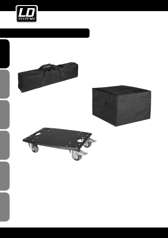
OPTIONAL ACCESSORIES:
LDM44SATBAG
Carrying bag for LDMAUI44 column loudspeakers
LDM44SUBPC
Protective cover for LDMAUI44 subwoofer
Similar to image
LDM44CB |
|
Castor board for LDMAUI44 |
Similar to image |
|
Similar to image
Prepare the MAUI44 column system for transport with the optional accessories:
1.Remove the upper and lower vertical array columns from the subwoofer one at a time.
2.With the help of the butterfly closures, fit the castor board to the back of the subwoofer. Ensure a tight fit.
3.Turn the subwoofer with attached castor board over onto a flat surface. Now, pull the protective cover over the subwoofer.
4.After the vertical array columns have been stowed in each bag, both can be placed on top of the subwoofer for transport. Be careful when rolling the unit on uneven surfaces such as door sills etc..
22

MANUFACTURER´S DECLARATIONS:
MANUFACTURER‘S WARRANTY
This warranty extends to the LD SYSTEMS branded product you purchased from Adam Hall. The statutory warranty rights against the vendor shall not be affected by this warranty. Rather, this warranty gives you additional independent claims against Adam Hall.
With this warranty, Adam Hall ensures that products you have purchased from Adam Hall or Adam Hall partners, under normal use, are free of defects in material or workmanship for a period of 2 years from the date of purchase. The warranty period begins on the date of purchase. In order to assert a claim for warranty service, the proof of date of purchase is provided by the receipt bearing the date of purchase or the date of purchase on the delivery note. You are entitled to warranty service under the conditions and provisions set out in this document, if a repair within the warranty period is required.
This warranty applies only to the original purchaser of the products supplied by Adam Hall and is not transferable to any person to whom the property is transferred by the original purchaser.
Within the warranty period, the defective parts or the product from Adam Hall will be repaired or replaced. Under the terms of this warranty, all the replaced or removed components become the property of Adam Hall.
In the unlikely event that a product acquired from Adam Hall, repeatedly exhibits a defect, Adam Hall may decide, at its discretion, to replace this product with a comparable product of at least the same performance.
Adam Hall does not guarantee that the operation of this product will be uninterrupted or error-free. Adam Hall accepts no responsibility for any damage due to incorrect compliance with the instructions received in the delivery.
This warranty does not extend to:
-wearing parts (eg battery, tubes).
-devices that have had their serial number removed or damaged, or failed as a result of an accident
-inappropriate or abusive use or other external causes
-devices that were not used in accordance with the operating parameters defined in the user documentation shipped with the product
-devices that have been repaired using parts not made or distributed by Adam Hall
-devices that have been serviced, modified or repaired by someone other than Adam Hall or an authorised service partner. These terms and conditions constitute the complete and exclusive warranty agreement between you and Adam Hall regarding the Adam Hall branded product you have purchased.
This warranty is valid only within Europe. Outside of Europe please contact our official distributors.
ESPAÑOL FRANCAIS DEUTSCH ENGLISH
ITALIANO POLSKI
23
ESPAÑOL FRANCAIS DEUTSCH ENGLISH
POLSKI
ITALIANO
MANUFACTURER´S DECLARATIONS:
LIMITATION OF LIABILITY
If your Adam Hall branded hardware product fails to work as warranted above, your sole and exclusive remedy shall be repair or replacement. Adam Halls’ maximum liability under this limited warranty is expressly limited to the lesser of the price you have paid for the product or the cost of repair or replacement of any components that malfunction under conditions of normal use.
Adam Hall is not liable for any damages caused by the product or the failure of the product, including any lost profits or savings or special, incidental, or consequential damages. Adam Hall is not liable for any claim made by a third party or made by you for a third party.
This limitation of liability applies whether damages are sought, or claims are made, under this Limited Warranty or as a tort claim (including negligence and strict product liability), a contract claim, or any other claim, and cannot be rescinded or changed by anyone. This limitation of liability will be effective even if you have advised Adam Hall or an authorized representative of Adam Hall of the possibility of any such damages, but not, however, in the event of claims for damages in connection with personal injuries.
This manufacturer‘s warranty grants you specific rights; depending on jurisdiction (nation or state), you may be be entitled to additional claims. You are advised to consult applicable state or national laws for a full determination of your rights.
REQUESTING WARRANTY SERVICE
To request warranty service for the product, contact Adam Hall or the Adam Hall authorized reseller from which you purchased the product.
EC DECLARATION OF CONFORMITY
The equipment marketed by Adam Hall complies (where applicable) with the essential requirements and other relevant specifications of Directives 1999/5/EC (R&TTE), 2004/108/EC (EMC) und 2006/95/EC (LVD). Additional information can be found at www.adamhall.com.
24

MANUFACTURER´S DECLARATIONS:
PROPER DISPOSAL OF THIS PRODUCT
(Valid in the European Union and other European countries with waste separation)
This symbol on the product, or the documents accompanying the product, indicates that this appliance may not be treated as household waste. This is to avoid environmental damage or personal injury due to uncontrolled waste disposal. Please dispose of this product separately from other waste and have it recycled to promote sustainable economic activity.
Household users should contact either the retailer where they purchased this product, or their local government office, for details on where and how they can recycle this item in an environmentally friendly manner.
Business users should contact their supplier and check the terms and conditions of the purchase contract. This product should not be mixed with other commercial wastes for disposal .
ENVIRONMENTAL PROTECTION AND ENERGY CONSERVATION
Energy conservation is an active contribution to environmental protection. Please turn off all unneeded electrical devices. To prevent unneeded devices from consuming power in standby mode, disconnect the mains plug.
Adam Hall GmbH, all rights reserved. The technical data and the functional product characteristics can be subject to modifications. The photocopying, the translation, and all other forms of copying of fragments or of the integrlity of this user’s manual is prohibited.
ESPAÑOL FRANCAIS DEUTSCH ENGLISH
ITALIANO POLSKI
25

ESPAÑOL FRANCAIS DEUTSCH ENGLISH
POLSKI
ITALIANO
Sie haben die richtige Wahl getroffen!
Dieses Gerät wurde unter hohen Qualitätsanforderungen entwickelt und gefertigt, um viele Jahre einen reibungslosen Betrieb zu gewährleisten. Dafür steht LD Systems mit seinem Namen und der langjährigen Erfahrung als Hersteller hochwertiger Audioprodukte.
Bitte lesen Sie diese Bedienungsanleitung sorgfältig, damit Sie Ihr neues Produkt von LD Systems schnell optimal einsetzen können.
Mehr Informationen zu LD SYSTEMS finden Sie auf unserer Internetseite WWW.LD-SYSTEMS.COM
Einführung
Das LD Systems MAUI44 Säulen PA-System wurde für den professionellen Einsatz konzipiert. Das PA-System bietet hochwertige Komponenten, DSP-gesteuerte Endstufen und einen über das gesamte Frequenzspektrum ausgewogenen Klang. Die digitale Signalbearbeitung des LD LECC DSP umfasst Funktionen wie Frequenzweiche, Equalizer, Kompressor und Limiter, und ist speziell auf das MAUI44 PA-System abgestimmt, um jederzeit eine optimale Audio-Leistung zur Verfügung zu stellen.
Das nach dem „Plug-and-Play“-Prinzip konzipierte System kommt ohne zusätzliche Kabel oder Stative aus und lässt sich daher schnell und einfach aufund abbauen.
26

LD MAUI44
KOMPAKTES SÄULEN PA SYSTEM AKTIV
LD MAUI44SE
SUBWOOFER ERWEITERUNG
ESPAÑOL FRANCAIS DEUTSCH ENGLISH
ITALIANO POLSKI
27

ESPAÑOL FRANCAIS DEUTSCH ENGLISH
POLSKI
ITALIANO
SICHERHEITSHINWEISE:
1.Lesen Sie diese Anleitung bitte sorgfältig durch.
2.Bewahren Sie alle Informationen und Anleitungen an einem sicheren Ort auf.
3.Befolgen Sie die Anweisungen.
4.Beachten Sie alle Warnhinweise. Entfernen Sie keine Sicherheitshinweise oder andere Informationen vom Gerät.
5.Verwenden Sie das Gerät nur in der vorgesehenen Art und Weise.
6.Verwenden Sie ausschließlich stabile und passende Stative bzw. Befestigungen (bei Festinstallationen). Stellen Sie sicher, dass Wandhalterungen ordnungsgemäß installiert und gesichert sind. Stellen Sie sicher, dass das Gerät sicher installiert ist und nicht herunterfallen kann.
7.Beachten Sie bei der Installation die für Ihr Land geltenden Sicherheitsvorschriften.
8.Installieren und betreiben Sie das Gerät nicht in der Nähe von Heizkörpern, Wärmespeichern, Öfen oder sonstigen Wärmequellen. Sorgen Sie dafür, dass das Gerät immer so installiert ist, dass es ausreichend gekühlt wird und nicht überhitzen kann. Direkte Sonneneinstrahlung vermeiden!
9.Platzieren Sie keine Zündquellen wie z.B. brennende Kerzen auf dem Gerät.
10.Lüftungsschlitze dürfen nicht blockiert werden.
11.Betreiben Sie das Gerät nicht in unmittelbarer Nähe von Wasser. Bringen Sie das Gerät nicht mit brennbaren Materialien, Flüssigkeiten oder Gasen in Berührung.
12.Sorgen Sie dafür, dass kein Tropfoder Spritzwasser in das Gerät eindringen kann. Stellen Sie keine mit Flüssigkeit gefüllten Behältnisse wie Vasen oder Trinkgefäße auf das Gerät.
13.Sorgen Sie dafür, dass keine Gegenstände in das Gerät fallen können.
14.Betreiben Sie das Gerät nur mit dem vom Hersteller empfohlenen und vorgesehenen Zubehör.
15.Öffnen Sie das Gerät nicht und verändern Sie es nicht.
16.Überprüfen Sie nach dem Anschluss des Geräts alle Kabelwege, um Schäden oder Unfälle, z. B. durch Stolperfallen zu vermeiden.
17.Achten Sie beim Transport darauf, dass das Gerät nicht herunterfallen und dabei möglicherweise Sachund Personenschäden verursachen kann.
18.Wenn Ihr Gerät nicht mehr ordnungsgemäß funktioniert, Flüssigkeiten oder Gegenstände in das Geräteinnere gelangt sind, oder das Gerät anderweitig beschädigt wurde, schalten Sie es sofort aus und trennen es von der Netzsteckdose (sofern es sich um ein aktives Gerät handelt). Dieses Gerät darf nur von autorisiertem Fachpersonal repariert werden.
19.Verwenden Sie zur Reinigung des Geräts ein trockenes Tuch.
20.Beachten Sie alle in Ihrem Land geltenden Entsorgungsgesetze. Trennen Sie bei der Entsorgung der Verpackung bitte Kunststoff und Papier bzw. Kartonagen voneinander.
21.Kunststoffbeutel müssen außer Reichweite von Kindern aufbewahrt werden.
BEI GERÄTEN MIT NETZANSCHLUSS:
22.ACHTUNG: Wenn das Netzkabel des Geräts mit einem Schutzkontakt ausgestattet ist, muss es an einer Steckdose mit Schutzleiter angeschlossen werden. Deaktivieren Sie niemals den Schutzleiter eines Netzkabels.
23.Schalten Sie das Gerät nicht sofort ein, wenn es starken Temperaturschwankungen ausgesetzt war (beispielsweise nach dem Transport). Feuchtigkeit und Kondensat könnten das Gerät beschädigen. Schalten Sie das Gerät erst ein, wenn es Zimmertemperatur erreicht hat.
24.Bevor Sie das Gerät an die Steckdose anschließen, prüfen Sie zuerst, ob die Spannung und die Frequenz des Stromnetzes mit den auf dem Gerät angegebenen Werten übereinstimmen. Verfügt das Gerät über einen Spannungswahlschalter, schließen Sie das Gerät nur an die Steckdose an, wenn die Gerätewerte mit den Werten des Stromnetzes übereinstimmen. Wenn das mitgelieferte Netzkabel bzw. der mitgelieferte Netzadapter nicht in Ihre Netzsteckdose passt, wenden Sie sich an Ihren Elektriker.
25.Treten Sie nicht auf das Netzkabel. Sorgen Sie dafür, dass spannungsführende Kabel speziell an der Netz-
28

SICHERHEITSHINWEISE:
buchse bzw. am Netzadapter und der Gerätebuchse nicht geknickt werden.
26.Achten Sie bei der Verkabelung des Geräts immer darauf, dass das Netzkabel bzw. der Netzadapter stets frei zugänglich ist. Trennen Sie das Gerät stets von der Stromzuführung, wenn das Gerät nicht benutzt wird, oder Sie das Gerät reinigen möchten. Ziehen Sie Netzkabel und Netzadapter immer am Stecker bzw. am Adapter und nicht am Kabel aus der Steckdose. Berühren Sie Netzkabel und Netzadapter niemals mit nassen Händen.
27.Schalten Sie das Gerät möglichst nicht schnell hintereinander ein und aus, da sonst die Lebensdauer des Geräts beeinträchtigt werden könnte.
28.WICHTIGER HINWEIS: Ersetzen Sie Sicherungen ausschließlich durch Sicherungen des gleichen Typs und Wertes. Sollte eine Sicherung wiederholt auslösen, wenden Sie sich bitte an ein autorisiertes Servicezentrum.
29.Um das Gerät vollständig vom Stromnetz zu trennen, entfernen Sie das Netzkabel bzw. den Netzadapter aus der Steckdose.
30.Wenn Ihr Gerät mit einem verriegelbaren Netzanschluss bestückt ist, muss der passende Gerätestecker entsperrt werden, bevor er entfernt werden kann. Das bedeutet aber auch, dass das Gerät durch ein Ziehen am Netzkabel verrutschen und herunterfallen kann, wodurch Personen verletzt werden und/oder andere Schäden auftreten können. Verlegen Sie Ihre Kabel daher immer sorgfältig.
31.Entfernen Sie Netzkabel und Netzadapter aus der Steckdose bei Gefahr eines Blitzschlags oder wenn Sie das Gerät länger nicht verwenden.
CAUTION |
RISK OF ELECTRIC SHOCK |
DO NOT OPEN |
ACHTUNG:
Entfernen Sie niemals die Abdeckung, da sonst das Risiko eines elektrischen Schlages besteht. Im Inneren des Geräts befinden sich keine Teile, die vom Bediener repariert oder gewartet werden können. Lassen Sie Reparaturen ausschließlich von qualifiziertem Servicepersonal durchführen.
Das gleichschenkelige Dreieck mit Blitzsymbol warnt vor nichtisolierten, gefährlichen Spannungen im Geräteinneren, die einen elektrischen Schlag verursachen können.
Das gleichschenkelige Dreieck mit Ausrufungszeichen kennzeichnet wichtige Bedienungsund Wartungshinweise.
ACHTUNG HOHE LAUTSTÄRKEN BEI AUDIOPRODUKTEN!
Dieses Gerät ist für den professionellen Einsatz vorgesehen. Der kommerzielle Betrieb dieses Geräts unterliegt den jeweils gültigen nationalen Vorschriften und Richtlinien zur Unfallverhütung. Als Hersteller ist Adam Hall gesetzlich verpflichtet, Sie ausdrücklich auf mögliche Gesundheitsrisiken hinzuweisen.
Gehörschäden durch hohe Lautstärken und Dauerbelastung: Bei der Verwendung dieses Produkts können hohe Schalldruckpegel (SPL) erzeugt werden, die bei Künstlern, Mitarbeitern und Zuschauern zu irreparablen Gehörschäden führen können.
Um eine mögliche Schädigung des Hörsinns zu verhindern, vermeiden Sie das Hören bei großem Lautsärkepegel über lange Zeiträume.
Lauter Schalleinfluss kann selbst bei kurzer Dauer zu Hörschäden führen. Bitte halten Sie die Laustärke immer auf einem angenehmen Level.
ESPAÑOL FRANCAIS DEUTSCH ENGLISH
ITALIANO POLSKI
29

FRNCAISITALIANO POLSKIFRANCAIS ESPAÑOL FRANCAIS DEUTSCH ENGLISH
AUFBAU, ANSCHLUSS UND INBETRIEBNAHME:
ALLGEMEINE HINWEISE
Sowohl der Subwoofer des LD Systems MAUI44 PA-Systems, als auch die Subwoofer-Erweiterung MAUI44SE müssen vor der Inbetriebnahme auf ebener Fläche auf ihre Gummifüße gestellt werden. Betreiben Sie das System niemals auf einem Rollwagen, da die Gefahr besteht, dass sich das gesamte System unkontrolliert in Bewegung setzt. Unfälle und Beschädigungen können die Folge sein. Die Kühlung der Endstufe erfolgt über die Lüftungsschlitze im Anschlussfeld auf der Rückseite des Subwoofers. Um eine ausreichende Kühlung zu gewährleisten, muss bei Betrieb zwischen der Rückseite des Subwoofers und anderen Objekten wie Wänden o. ä. ein Mindestabstand von 50 cm eingehalten werden.
Bitte achten Sie bei dem System sowie den angeschlossenen Geräten wie Mischpulten, CD-Playern etc. auf den korrekten Anschluss von Audiound Stromverbindungen. Verwenden Sie ausschließlich unbeschädigte Kabel mit geeignetem Durchmesser und rollen Sie Kabelrollen immer vollständig ab. Verwenden Sie gegebenenfalls Kabelbrücken, um Stolperfallen durch lose Kabel zu vermeiden. Stellen Sie Gerät niemals direkt an einer Kante auf. Positionieren Sie den Subwoofer nicht auf einem Tisch. Um ungewollte Nebengeräusche beim Einschalten angeschlossener Geräte zu vermeiden, schalten Sie das System immer als letztes Gerät ein und als erstes Gerät aus.
AUFBAU
Das LD Systems MAUI44 PA-System besteht aus drei Komponenten:
ASubwoofer mit integrierter Elektronik für alle Systemkomponenten.
BUntere Vertical-Array-Säule mit acht 3,5“ Lautsprechern, 2 mehrpoligen Anschlüssen und den Führungsbolzen. Da die untere Säule über eine spezielle Schaltung verfügt und die Anschlussfelder an beiden Enden identisch sind, ist es irrelevant, welches der beiden Anschlussfelder auf den Subwoofer aufgesteckt wird.
CDie obere Vertical-Array-Säule mit acht 3,5“ Lautsprechern, den Hochtönern und einem Multipin-Anschluss auf der Unterseite.
Nachdem der Subwoofer an der gewünschten Stelle aufgestellt wurde, wird zunächst die untere Array-Säule auf den Subwoofer aufgesteckt. Stabile Stahlstifte helfen dabei, dass die Multipin-Stecker beider Lautsprecher perfekt ineinander greifen. Die obere Vertical-Array-Säule wird nun nach dem gleichen Prinzip auf die untere Säule aufgesteckt. Um den Transport, sowie Aufund Abbau zu erleichtern, sind auf der Rückseite der Array-Säulen Griffe im oberen und unteren Bereich angebracht. Die Griffe können je nach Bedarf abmontiert werden (5 mm Innensechskant).
Die MAUI44SE Subwoofer-Erweiterung kann grundsätzlich sowohl neben, als auch unter der MAUI44 Säulenanlage positioniert werden. Für die Positionierung unter der MAUI44 Säulenanlage befinden sich auf der Oberseite des Subwoofers 4 Vertiefungen, in die die Gummifüße des MAUI44 Subwoofers exakt hineinpassen. Somit wird ein Verrutschen der MAUI44 Säulenanlage auf dem MAUI44SE Subwoofer effektiv verhindert. Stecken Sie die Array-Säulen auf den MAUI44 Subwoofer erst nachdem Sie beide Subwoofer übereinander gestellt haben.
ANSCHLUSS UND BETRIEB
Am Gerät lässt sich sowohl die Lautstärke des gesamten Systems als auch die Lautstärke des Subwoofers im Verhältnis zur Gesamtlautstärke einstellen. Zuspielgeräte lassen sich sowohl über symmetrische als auch unsymmetrische Kabel (XLR / 6,3 mm Klinke / Cinch) anschließen. Wird der MAUI44SE Subwoofer als Erweiterung für die MAUI44 Säulenanlage verwendet, wird die optimale Ansteuerung durch die MAUI44 Säulenanlage unter Beachtung folgender Schritte erreicht: Bringen Sie den Schalter DSP MODE in die rechte Position SLAVE (MAUI44) und verbinden den Line-Ausgang SLAVE SUB OUT (MAUI44SE) der MAUI44 Säulenanlage mit dem Line-Eingang SLAVE SUB IN (MAUI44) des MAUI44SE Subwoofers unter Verwendung eines symmetrischen XLR-Kabels. Befindet sich der Schalter DSP MODE in Position SLAVE (MAUI44), sind die Bedienelemente SUB LEVEL, SUB FREQ und SUB PHASE, sowie der linke Line-Eingang LINE INPUT LEFT deaktiviert.
30
 Loading...