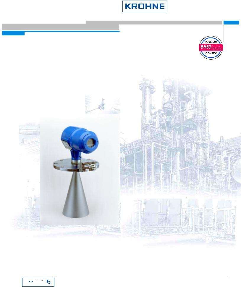
KROHNE BM702 User Manual

© KROHNE 12/2000
Remote Operation
Instructions
HART Communicator 275
Asset Management Solutions (AMS)
BM 70 A/P, BM 700, BM 702
|
|
|
|
|
|
|
|
|
|
|
|
|
|
|
|
|
|
|
|
|
|
|
|
|
|
|
|
|
KROHNE Messtechnik GmbH & Co. KG · Ludwig-Krohne-Str. 5 ! D-47058 Duisburg |
1/10 |
|
|
|
|
|
|
|
|
|
|
|
|
|
|
|
|
|
|
|
|
|
|
|
|
|
|
|
|
|
Tel.: 0203-301 0 ! Fax: 0203-301 389 · e-mail: krohne@krohne.de |
|

Remote Operation Instructions BM 70 A/P, BM 700, BM 702 HART
1 |
General Information |
3 |
|
|
1.1 |
Configuring Instruments for Multidrop |
3 |
2 |
IDs and Revision numbers |
3 |
|
3 |
Implementation Peculiarities |
3 |
|
4 |
HART Communicator 275 (HC275) |
4 |
|
|
4.1 |
Installation |
4 |
|
4.2 |
Operating |
4 |
|
4.3 |
Known HC275 (4.9) Shortcomings |
4 |
5 |
Asset Management Solutions (AMS) |
4 |
|
|
5.1 |
Installation |
4 |
|
5.2 |
Operating |
5 |
|
5.3 |
Known AMS (5.0) Shortcomings |
6 |
|
|
|
|
|
|
|
|
|
|
|
|
|
|
|
|
|
|
|
|
|
|
|
|
|
|
|
|
|
|
KROHNE Messtechnik GmbH & Co. KG · Ludwig-Krohne-Str. 5 ! D-47058 Duisburg |
2/10 |
|
|
|
|
|
|
|
|
|
|
|
|
|
|
|
|
|
|
|
|
|
|
|
|
|
|
|
|
|
|
Tel.: 0203-301 0 ! Fax: 0203-301 389 · e-mail: krohne@krohne.de |
|

Remote Operation Instructions BM 70 A/P, BM 700, BM 702 HART
1 General Information
The BM 70 A/P, BM 700, BM 702 are all the two-wire transmitters with 4..20mA current output and HART® capability.
General characteristics of the BM70 X HART® interface:
•Multidrop Mode is supported.
•Burst Mode is not supported.
Electrical connection (point-to-point or multidrop): refer to sections 4.1 – 4.4 of the „Installation and Operating Instructions. BM 70 A/P, BM 700, BM 702“.
1.1 Configuring Instruments for Multidrop
There are differences in configuring instruments for multidrop mode from remote or via device local keypad.
•If the instrument is entering multidrop via HART® interface (any application can be used), i.e. its bus address is changed from ‘0’ to any allowed, then all the necessary operation with the instrument current output are done automatically (by the HART® transmitter).
•If the instrument local keypad is used, the user must manually carry out the three assignments:
1.Set the desirable bus address (Fct. 3.3.6),
2.Set the current output range to “4 – 20 mA” (Fct. 3.3.2),
3.Switch the current output function to “Off” (Fct. 3.3.1) and store configuration.
2 IDs and Revision numbers
The HART Device Descriptions described in this document have the following IDs and revision numbers:
Manufacturer ID: |
69 (0x45) |
|
Device Type: |
249 (0xF9) |
|
Device Revision: |
11 (0x0B) |
|
DD Revision: |
2 |
|
HART Universal Revision: |
5 |
|
HC 275 OS Revision: |
≥ |
4.9 |
AMS Version: |
≥ |
5.0 |
For information about Transmitter Revisions and related Device Descriptions refer to the KROHNE HART Device List.
3 Implementation Peculiarities
As for all previous BM 70 X DD revisions there are some implementation peculiarities, caused by either restrictions of the DDL / AMS or introduced deliberately – to restrict the usage/access to some device functionality.
The list of implementation peculiarities/restrictions follows:
•The values in the Service menu are generally set by Krohne or possibly by the Service technician, and remain unchanged in operation. The user should not have access to these values. Therefore the service data is made inaccessible for offline device configuration (it is open for live device provided the user is capable to get authorization as specialist).
•The Conversion Table is excluded from offline data for HC275 whilst for AMS it is possible to configure it offline.
•The BM 70 A/P /700 /702 HART® transmitter interacts with the instrument mastering SW via special interface functions. Their actual set impose some display-related restrictions: functions Test Display (2.1.2 – tests the HW of the display) and Display Firmware (2.4.2) are not supported by the HART® interface. Besides, the complete display submenu (3.2) is left out (i.e. is not maintained by the instrument HART® application layer) – the local instrument user might configure the display settings without any impact on the remote HART® bus master. Hence one important consequence must be pointed out: the units for measurements on HC275 screens/AMS faceplates coincide with the ones for configuration parameters (say, for ‘Level’ measurements – with the units for ‘Tank height’, ‘Block distance’, etc.) but not with the ones that are set via display menu (3.2.2, 3.2.3). If the user
|
|
|
|
|
|
|
|
|
|
|
|
|
|
|
|
|
|
|
|
|
|
|
|
|
|
|
|
|
|
KROHNE Messtechnik GmbH & Co. KG · Ludwig-Krohne-Str. 5 ! D-47058 Duisburg |
3/10 |
|
|
|
|
|
|
|
|
|
|
|
|
|
|
|
|
|
|
|
|
|
|
|
|
|
|
|
|
|
|
Tel.: 0203-301 0 ! Fax: 0203-301 389 · e-mail: krohne@krohne.de |
|
 Loading...