


© KROHNE
 7.02226.31.00
Installation and operating instructions
Level-Radar
BM 700
|
|
Variable area flowmeters |
|
|
Vortex flowmeters |
|
|
Flow controllers |
|
|
Electromagnetic flowmeters |
|
|
Ultrasonic flowmeters |
|
|
Mass flowmeters |
|
|
Level measuring instruments |
|
|
Communications technology |
|
Status: 06-1999 |
Engineering systems & solutions |
|
||
|
|
|

Software History
Intro- |
Signal converter |
|
User program |
Instructions |
|||
duction |
|
|
|
|
|
|
|
|
|
|
|
|
|
|
|
Mth./Yr |
Hardware |
Firmware |
Hardware |
Operating- |
Software |
Device |
User |
|
|
|
|
system |
|
|
program |
|
|
|
|
|
|
|
|
04/98 |
BM 700 |
5.00PREnn |
PC |
DOS 5.0 |
PC-CAT |
Suppl. |
7.02221.11 |
|
|
5.01PRE01 |
|
and higher |
3.00 |
instruction |
+ Suppl. |
|
|
|
|
|
PREnn |
to BM 70A |
instruction |
|
|
|
|
|
|
|
|
Test versions for BM 700. |
|
|
|
|
|
||
|
|
|
|
|
|
|
|
|
|
|
|
|
|
|
|
10/98 |
BM 700 |
5.01 |
PC |
DOS 5.0 |
PC-CAT |
10/98 |
7.02221.11 |
|
|
|
|
and higher |
3.00 |
|
+ Suppl. |
|
|
|
|
|
|
|
instruction |
|
|
|
|
|
|
|
|
First serial version for BM 700. |
|
|
|
|
|
||
|
|
|
|
|
|
|
|
|
|
|
|
|
|
|
|
|
|
|
|
|
|
|
|
|
|
|
|
|
|
|
|
|
|
|
|
|
|
|
|
|
|
|
|
|
|
|
|
|
|
|
|
|
|
|
|
Items included with supply
The scope of supply includes, in the version as ordered:
∙Signal converter bolted to waveguide window and antenna; optionally: antenna extension, sunshade (with fastening material in each case)
∙Shielding material with tightening strap (not for the US market)
∙Installation and operating instructions plus instruction card
∙Report on factory settings for the signal converter
∙Certification and approval documents, unless reproduced in the device documentation
∙Bar magnet for operator control (only for version with local display)
∙Wrench for covers
Installation material (stud bolts, flange gasket and cabling) not supplied, to be provided by customer!
Page 2 |
BM 700 Installation and Operating Instructions |

Contents:
|
|
page |
1 |
Handling and storage |
3 |
2 |
Installation |
4 |
2.1 |
Field assembly |
4 |
2.2 |
Mechanical installation |
5 |
3 |
Electrical connection |
7 |
4 |
Setting the parameters |
8 |
5 |
Maintenance, error handling |
16 |
6 |
Safety information |
17 |
7 |
Technical data (extract) |
18 |
8 |
BM 700 Level-Radar Type code |
19 |
9 |
Parameter check list BM 700 |
21 |
Appendix |
22 |
|
Product liability and warranty:
The BM 700 level gauge is designed solely for measuring the level, distance, volume and reflection of liquids, pastes, slurries, particulate materials and solids.
The BM 700 level gauge does not form part of an overfill protection system as defined in the WHG (= German water pollution regulation).
Local codes and regulations apply to its use in hazardous areas.
Responsibility as to suitability and intended use of these level gauges rests solely with the user.
Improper installation and operation of our level gauges may lead to loss of warranty.
In addition, the "General conditions of sale", form the basis of the purchasing contract.
If you need to return the level gauge to the manufacturer or supplier, please refer to the information given in Section 5
1 Handling and storage
Safety advice
Depending on the version, the device will weigh between approx. 10 kg and 30 kg. To carry, use both hands to lift the device carefully by the converter housing. If necessary, use lifting gear.
When handling the BM 700, avoid hard blows, jolts, impact, etc.
When storing the "Wave-Stick" version, make sure that the device is not placed on its side on the PTFE antenna, as this may cause the rod to bend.
BM 700 Installation and Operating Instructions |
Page 3 |
2 Installation
Most of the BM 700 versions are supplied in fully assembled condition. In this case, you may skip this chapter. However, if a device should be delivered in parts, or parts are subsequently replaced, the following should be noted.
2.1 Field assembly
∙For any necessary field assembly of the BM 700, all parts are included with the supply (stud bolts, washers, etc.).
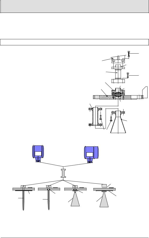
∙Bolt the waveguide window (flange mount) or distance piece, if supplied loose, to the BM 700. Torque for the sets of 4 Allen screws M (key size 5 mm): max. 8 Nm
0.8kpm (5.8 ft lbf).
∙Note: Ensure the upper Teflon plug is kept absolutely dry and clean! Moisture and dirt will impair functionability of the BM 700!
∙Bolt antenna extension to the antenna; torque for the 3 stud bolts A: max. 8 Nm
0.8kpm (5.8 ft lbf).
Do not detach bolts H !
|
M |
signal converter |
O-ring |
|
|
distance piece (for |
|
high-temperature version |
M |
up to 250°C (482 °F) |
H |
|
BM70 A |
upper Teflon plug |
connecting flange |
O-ring |
antenna extension |
lower Teflon plug |
|
antenna |
A |
|
Versions:
BM 700 |
BM 700 |
|
||
converter |
|
|||
converter |
|
|||
blind |
with Display |
|
||
|
|
High temperature |
|
|
|
|
distance piece |
|
|
|
|
|
(optional) |
Separation |
|
|
|
|
|
|
|
|
|
(Metaglass) |
Stick |
Flange |
Gasket |
Gasket |
Flange |
plate Stick |
Horn |
Horn |
plating |
|
|
(for Hastelloy, |
|||
|
|
antenna |
antenna |
|
|
|
Ti, Ta) |
||
|
|
|
|
|
Wave-Stick Wave-Stick
PTFE w/o plate (PP or PTFE)
max. max2 bar. (29barpsig)
LP flange system |
Flange system 96 |
max. 2 bar (29 psig) |
with horn antenna |
max. 2 bar |
|
with horn antenna |
|
Page 4 |
BM 700 Installation and Operating Instructions |
2.2 Mechanical installation
Hazardous-duty systems:
∙The BM 700 Ex is certified in conformity with European Standard for use in Zone 0, 1 and 2 hazardous locations (dependent on version).
∙Attention is drawn to the data and information given on the nameplate of the converter, the nameplate of the flange and the specifications in the approval certificates.
Safety:
∙Surface temperature: The housing of the signal converter can, in extreme ambient conditions, have a temperature of more than 70°C (158°F)!
∙Check material compatibility of antenna, extension, flange, gaskets, and PP or PTFE (used in all versions) with the product! See also section 8 "Type code"!
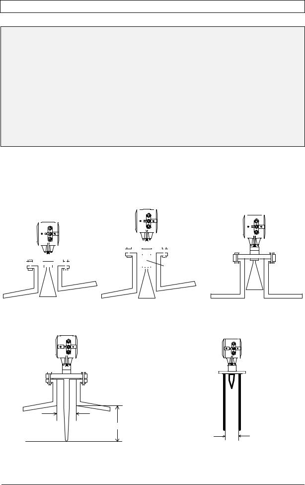
Mounting on the tank nozzle
a) Devices with horn antenna:
The antenna should project out of the nozzle. If necessary, use an antenna extension. Exception: in case of a symmetrical tank fitting.
|
|
|
|
|
|
|
|
|
|
|
|
|
|
|
|
|
|
|
|
|
|
|
|
|
|
|
|
|
|
|
|
|
|
|
|
|
|
|
|
|
|
|
|
|
|
|
|
|
|
|
|
|
|
|
|
|
|
|
|
|
|
|
|
|
|
|
|
|
|
|
|
|
|
|
|
|
|
|
|
|
|
|
|
|
|
|
|
|
|
|
|
|
|
|
|
|
|
|
|
|
|
|
|
|
|
|
|
|
|
|
|
|
|
|
|
|
|
|
|
|
|
|
|
|
|
|
|
|
|
|
|
|
|
|
|
|
|
|
|
|
|
|
|
|
|
|
|
|
|
|
|
|
|
|
|
|
|
|
|
|
|
|
|
|
|
|
|
|
|
|
|
|
|
|
|
|
|
|
|
|
|
|
|
|
|
|
|
|
|
|
|
|
|
|
|
|
|
|
|
|
|
|
|
|
|
|
|
|
|
|
|
|
|
|
|
|
|
|
|
|
|
|
|
|
|
|
|
|
|
|
|
|
|
|
|
|
|
|
|
|
|
|
|
|
|
|
|
|
|
|
|
|
|
|
|
|
|
|
|
|
|
|
|
|
|
|
|
|
|
|
|
|
|
|
|
|
|
|
|
|
|
|
|
|
|
|
|
|
|
|
|
|
|
|
|
|
|
|
|
|
|
|
|
|
|
|
|
|
|
|
|
|
|
|
|
|
|
|
|
|
|
|
|
|
|
|
|
|
|
|
|
|
|
|
|
|
|
|
|
|
|
|
|
|
|
|
|
|
|
|
|
|
|
|
|
|
|
|
|
|
|
|
|
|
|
|
|
|
|
|
|
|
|
|
|
|
|
|
|
|
|
|
|
|
|
|
|
|
|
|
|
|
|
|
|
|
|
|
|
|
|
|
|
|
|
|
|
|
|
|
|
|
|
|
|
|
|
|
|
|
|
|
|
|
|
|
|
|
|
|
|
|
|
|
|
|
|
|
|
|
|
|
|
|
|
|
|
|
|
|
|
|
|
|
|
|
|
|
|
|
|
|
|
|
|
|
|
|
|
|
|
|
|
|
|
|
|
|
|
|
|
|
|
|
|
|
|
|
|
|
|
|
|
|
|
|
|
|
|
|
|
|
|
|
|
|
|
|
|
|
|
|
|
|
|
|
|
|
|
|
|
|
|
|
|
|
|
|
|
|
|
|
|
|
|
|
|
|
|
|
|
|
|
|
|
|
|
|
|
|
|
|
|
|
|
|
|
|
|
|
|
|
|
|
|
|
|
|
|
|
|
|
|
|
|
|
|
|
|
Antenna |
|
|
|
|
|
|
|
|
|
|
|
||
|
|
|
|
|
|
|
|
|
|
|
|
|
|
|
|
|
|
|
|
|
Tank nozzle |
|
|
|
|
|
|
|
|
|
extension |
|
|
|
|
|
|
|
|
|
|
|
|||||||||||
|
|
|
|
|
|
|
|
|
|
|
|
|
|
|
|
|
|
|
|
|
|
|
|
|
|
|
|
|
|
|
|||||||||||||||||||||||
Tank nozzle
Tank nozzle
b) Wave-Stick
Note the requirements imposed on nozzle diameter and nozzle length:
tank nozzle
min. 50 mm
min. 235 mm
Version for still wells
dia. 40...55 mm (1.57" to 2.17") e.g. DN50 (2")
BM 700 Installation and Operating Instructions |
Page 5 |

c) Purging device
Remove screw plug ¼" R and screw in screwed tube joint, e.g. Ermeto ¼" R.
Consult “Ex“ specifications relating to the purging circuit (provided by customer)!
Installation on the tank
∙Do not forget the gasket when positioning the BM 700 on the tank nozzle flange. Align BM 700 and gasket, slightly tighten nuts on stud bolts (by hand).
∙Press shielding strip C* in the gap between tank and BM 700 flanges and secure with strap retainer S* (both items included with supply).
∙Strap retainer S* must fit closely and overlap both flanges.
*only required for European radio approvals
∙Tighten down stud bolt nuts firmly. The tightening torque is dependent upon the strength properties of the stud bolts and the pressure rating of the tank.
C* = shielding strip
S* = strap retainer
B = BM 700 flange F = tank flange
Positioning on the tank
|
|
|
|
|
|
|
|
|
|
|
|
|
|
|
|
|
|
|
|
|
|
|
|
|
|
|
|
|
|
|
|
|
|
|
|
|
|
|
|
|
|
|
|
|
|
|
|
|
|
|
|
|
|
|
|
|
|
|
|
|
|
|
|
|
|
|
|
|
|
|
|
|
|
|
|
|
|
|
|
|
|
|
|
|
|
|
|
|
|
|
|
|
|
|
|
|
|
|
|
|
|
|
|
|
|
|
|
>1/7×H, but max. 1/3×D |
|
H |
|
|
|
|
|
|
|
|
|||||||
|
|
|
|
|
|
|
|
|
|
|
|
|
|
|
|
||
|
|
|
|
|
|
|
|
|
|
|
|
|
|
|
|
|
|
|
|
|
|
|
|
|
|
|
|
|
|
|
|
|
|
|
|
|
|
|
|
|
D |
|
|
|
|
|
|
|
|
|
|
|
|
|
|
|
|
|
|
|
|
|
|
|
|
|
|
||||
Recommended distance |
Do not position in |
Do not position |
|||||||||||||||
from the tank wall |
|
|
|
tank centreline! |
above internals! |
||||||||||||
|
|
|
|
|
|
|
|
|
|
(multiple reflections!) |
(interference reflections!) |
||||||
A Stilling well or Wave-Guide may be mounted in any position on the tank!
When using the PTFE Wave-Stick in hazardous areas of Zone 0, any electrostatic charging of the stick, e.g. by flow of product, must be avoided!
Page 6 |
BM 700 Installation and Operating Instructions |

3 Electrical connection
To open the terminal compartment of the signal converter, first open the safety lock with an Allen key (size: 4 mm) and then use the enclosed special wrench to turn the cover anticlockwise.
Supply power
Variant |
Voltage range |
Recommended fuse protection |
24 V DCAC |
19.2 - 28.8 V DC or |
min. T 0.5 A |
|
20.4 - 26.4 V AC |
|
Terminal assignment
Supply power:
Terminal compartment BM 700:
Current output
|
1 |
2 |
|
32 |
31 |
|
|||||||
|
|
|
|
|
|
- |
+ |
|
|
||||
|
|
|
|
|
|
|
|
|
|
+ |
|||
|
|
|
|
|
|
|
|
|
|||||
|
|
|
|
|
|
|
|
|
|
||||
|
|
|
|
|
|
|
|
|
|
||||
Power supply |
|
|
|
|
- |
||||||||
24 V DC (+/-20%) |
|
|
|
|
|||||||||
|
4-20mA |
||||||||||||
|
|
or |
|
|
|
|
|||||||
|
|
|
|
|
max.350 Ω |
||||||||
24 V AC (+10/-15%) |
|||||||||||||
|
|
|
|
|
|
|
|||||||
|
< 300 mA |
|
|
|
|
|
|
|
|||||
External power supply "FEAS, type PSLC242":
|
|
|
|
|
|
|
|
|
|
|
230 V AC |
|
|
|
|
|
|
|
|
|
|
|
|
|
|
115 V AC |
||||
|
|
|
|
|
|
|
|
|
|
|
|
|
|
|
|
|
|
|
|
|
|
|
|
|
|
|
|
|
|
|
|
|
|
|
|
|
|
|
|
|
|
|
|
|
|
|
|
|
|
|
|
|
|
|
|
|
|
|
|
|
|
|
|
|
|
|
|
|
|
|
|
|
|
|
|
|
|
|
|
|
|
|
|
|
|
|
|
|
|
|
|
|
|
L1L1 |
|
3 |
4 |
|
N |
N |
|
|
|
|
L1L1 |
|
3 |
4 |
|
N |
N |
|
|
||||||||||
|
+ |
+ |
|
- |
- |
|
|
|
+ |
+ |
|
- |
- |
|
|
|
BM 700 (max. 5 instruments) |
|
BM 700 (max. 5 instruments) |
||||||||||||
Power supply galvanically insulated according to VDE 0551 Dimensions (W×H×D): 55×75×110 mm, usable for rail mounting
Class of protection
The BM 700 level gauge is designed for safety class 1 in conformity with VDE 0106
Part 1.
24 V DCAC supply
When connected to a “functional extra-low voltage with safety separation“ power source (SELV or PELV) in accordance with VDE 0100, Part 410 or equivalent (inter)national regulations, connection of a safety conductor (PE) is not required.
Equipotential bonding
When used in hazardous areas, the BM 700 Ex must be incorporated in the PA equipotential bonding system , irrespective of the type of power supply! If the PA is connected via a separate conductor, this must be connected to the separate U-clamp terminal at the “neck“ of the BM 700 Ex. Cancellation ofquipotential bonding is only permitted when the BM 700 is disconnected from supply.
Rated temperature of connecting cables: see Section 6.
BM 700 Installation and Operating Instructions |
Page 7 |
4 Setting the parameters
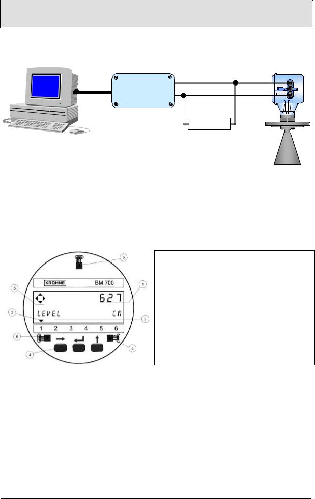
Setting parameters via program PC-CAT
RS232 Adapter
³ 120 W
With the program PC-CAT, version 3.00 or higher, you can configurate BM 700 instruments in a very comfortable way form a PC. Connect the current output of
BM 700 over a load between 120 Ω and 350 Ω to the Smart adapter (delivered together with PC-CAT) and connect it with a serial port of the PC.
Local display (optional)
• Numeric display, measured values
‚ Alphanumeric display, function/unit
ƒ Max. 6 markers to display measurement status
„ 3 keys for configuration and error interrogation
… Magnetic sensors for operator control through the closed housing (function same as the 3 keys)
† Compass field, indicates actuation of a key
Page 8 |
BM 700 Installation and Operating Instructions |
 Loading...