

Page 1

Engine Mechanical System
General Information
Engine Mechanical System
Page 2
2009 > D 2.9 VGT >
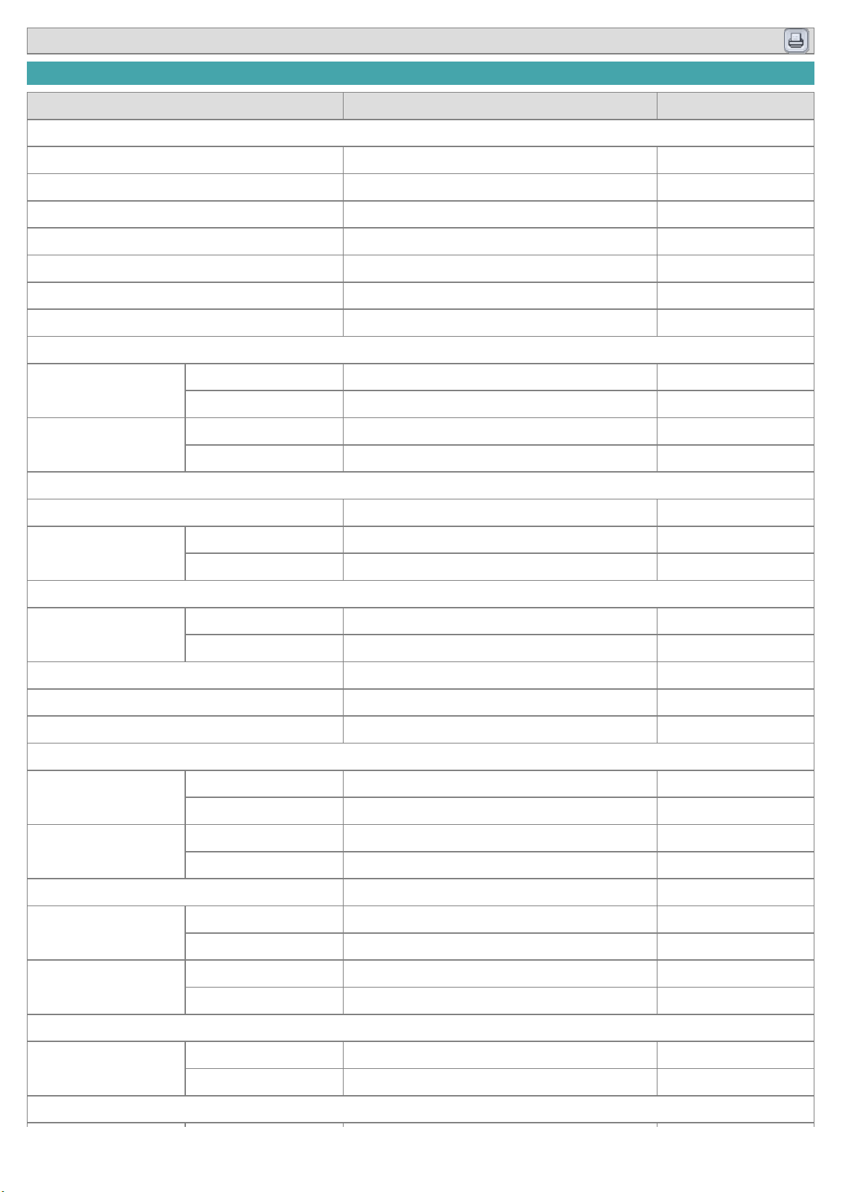
SPECIFICATIONS
Description Specifications(J3 - ENG) Limit
General
Type In-line, DOHC
Number of cylinders 4
Bore 101.5~101.526mm (3.9961~3.9971in)
Stroke 98mm (8.8583in)
Total displacement 2,902 cc (177.08 cu.in)
Compression ratio 18.4 : 1
Firing order 1-3-4-2
Valve timing
Intake valve
Opens (ATDC) 26°
Closes (ABDC) 50°
Exhaust valve
Opens (BBDC) 72°
Closes (ATDC) 32°
Cylinder head
Flatness of gasket surface Less than 0.05mm (0.0020in)
Flatness of manifold
mounting surface
Intake Less than 0.15mm (0.0059in)
Exhaust Less than 0.15mm (0.0059in)
Camshaft
Cam height
Intake 39.397 ~ 39.597mm (1.5511 ~ 1.5589in)
Exhaust 39.4932 ~ 39.6932mm (1.5548 ~ 1.5627in)
Journal outer Diameter (Intake, Exhaust) 27.941 ~ 27.960mm (1.1000 ~ 1.1008in)
Bearing oil clearance 0.040 ~ 0.080mm (0.0016 ~ 0.0031in)
End play 0.08 ~ 0.17mm (0.0031 ~ 0.0067in)
Valve
Valve length
Intake 126.24mm (4.9701in)
Exhaust 126.24mm (4.9701in)
Stem outer diameter
Intake 6.965 ~ 6.980mm (0.2742 ~ 0.2748in)
Exhaust 6.945 ~ 6.960mm (0.2734 ~ 0.2740in)
Face angle 45°
Thickness of valve
head (margin)
Intake 1.7mm (0.0669in)
Exhaust 1.6mm (0.0630in)
Valve stem to valve
guide clearance
Intake 0.030 ~ 0.065mm (0.0012 ~ 0.0026in)
Exhaust 0.050 ~ 0.085mm ( 0.0020~ 0.0033in)
Valve guide
Length
Intake 52.5mm (2.0669in)
Exhaust 52.5mm (2.0669in)
Valve seat
Page 3
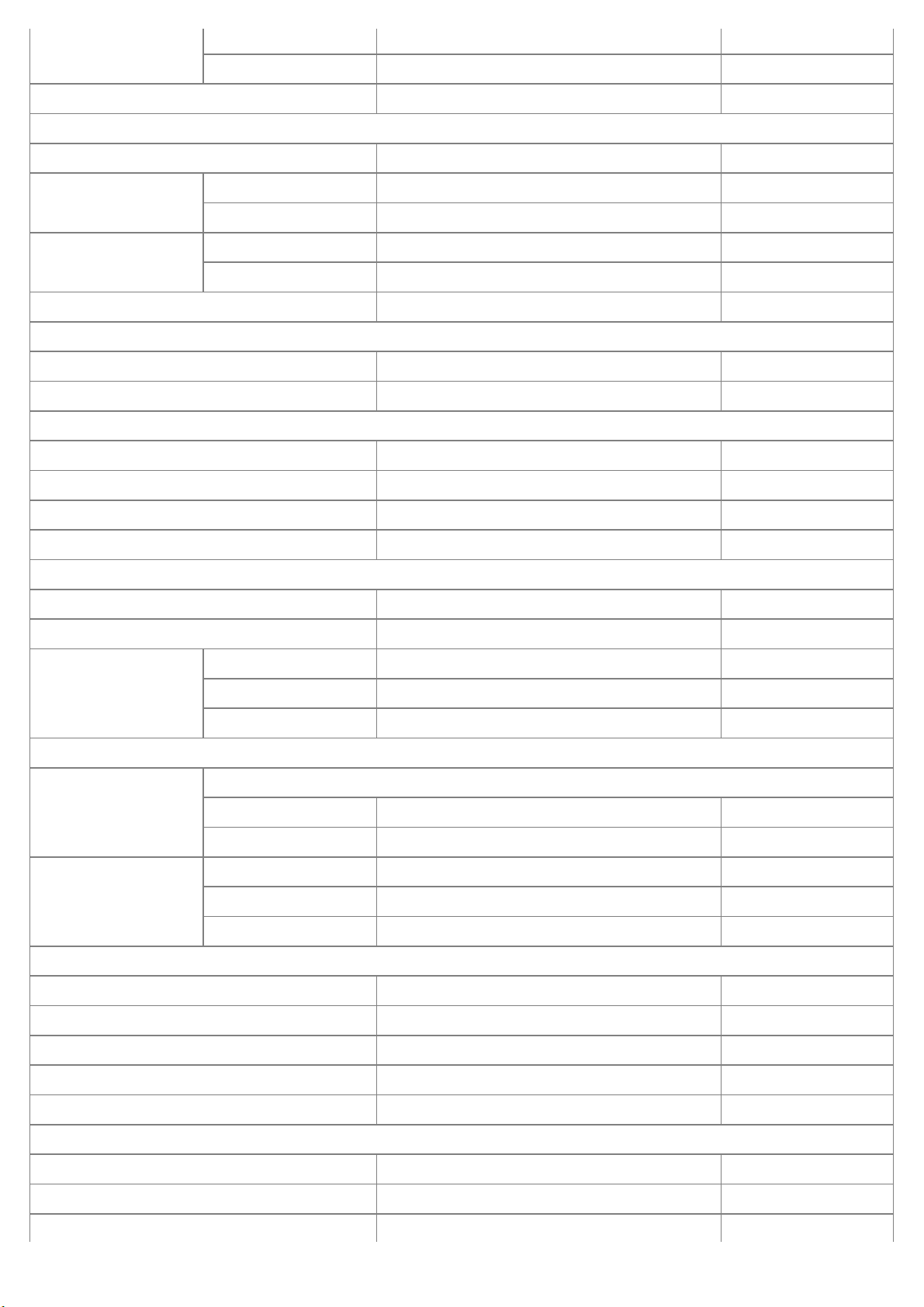
Width of seat contact
Intake 1.4 ~ 2.0mm (0.0551 ~ 0.0787in)
Exhaust 0.9 ~ 1.5mm (0.0354 ~0.0591 in)
Seat angle 45°
Valve spring
Free length 52.477mm (2.0660in)
Load(Intake)
Installed 23.45±1.87kg/40.0mm(51.7±4.1lb/1.5748 in)
Valve opened 39.15±3.13kg/31.65mm(86.3±6.9 lb/1.2461 in)
Load(Exhaust)
Installed 23.45±1.87kg/40.0mm(51.7±4.1lb/1.5748 in)
Valve opened 39.43±3.15kg/31.50mm(86.9±6.9 lb/1.2402 in)
Out of squareness Less than 2° 3°
Rocker arm and rocker arm shaft
Rocker arm inner diameter 20.000 ~ 20.027mm (0.7874 ~ 0.7885in)
Rocker arm shaft outer diameter 19.959 ~ 19.980mm (0.7858 ~ 0.7866in)
Cylinder block
Cylinder bore 101.500 ~ 101.526mm (3.9961 ~3.9971 in)
Liner inner diameter 97.100 ~ 97.126mm (3.8228~ 3.8239in)
Liner outer diameter 101.480 ~ 101.526mm ( 3.9953~ 3.9971in)
Flatness of gasket surface Less than 0.05mm (0.0020in)
Piston
Piston outer diameter 97.015 ~ 97.030mm ( 3.8195~ 3.8201in)
Piston to cylinder clearance 0.070 ~ 0.098mm (0.0028 ~ 0.0039in)
Ring groove width
No. 1 ring groove 2.397 ~ 2.417mm ( 0.0944~0.0952 in)
No. 2 ring groove 2.05 ~ 2.07mm ( 0.0807~ 0.0815in)
Oil ring groove 3.02 ~ 3.04mm (0.1189 ~ 0.1197in)
Piston ring
Side clearance No. 2 ring 0.06 ~ 0.10mm (0.0024~0.0039 in)
Oil ring 0.03 ~ 0.07mm (0.0012~0.0028 in)
End gap
No. 1 ring 0.25 ~ 0.40mm (0.0098~ 0.0157in)
No. 2 ring 0.40 ~ 0.55mm (0.0157~0.0217in)
Oil ring 0.20 ~ 0.40mm (0.0079 ~ 0.0157in)
Piston pin
Piston pin outer diameter 31.994 ~ 32.000mm (1.2596 ~ 1.2598 in)
Piston pin hole inner diameter 32.015 ~ 32.025mm (1.2604 ~ 1.2608 in)
Piston pin hole clearance 0.015 ~ 0.031mm (0.0006 ~ 0.0012 in)
Connecting rod small end inner diameter 32.012 ~ 32.033mm (1.2603 ~ 1.2611 in)
Connecting rod small end hole clearance 0.012 ~ -0.039mm (0.0005 ~ 0.0015 in)
Connecting rod
Connecting rod big end inner diameter 60.833 ~ 60.846mm (2.3950 ~ 2.3955 in)
Connecting rod bearing oil clearance 0.043 ~ 0.077mm (0.0017 ~ 0.0030 in)
End play 0.239~0.39 (0.0094 ~ 0.0154 in)
Page 4
Crankshaft
Main journal outer
diameter
NO 1, 2, 4, 5 69.995 ~ 70.015mm (2.7557 ~2.7565 in)
NO 3 69.973~69.993mm (2.7548 ~2.7556 in)
Pin journal outer diameter 57.106~57.124mm (2.2483~2.2490 in)
Main bearing oil
clearance
NO 1, 2, 4, 5 0.045 ~ 0.079mm (0.0018 ~0.0031 in)
NO 3 0.067~0.101 mm (0.0026 ~0.0040 in)
End play 0.14 ~ 0.39mm (0.0055 ~0.0154 in)
Flywheel
Runout 0.10mm (0.0039in) 0.13mm (0.0051in)
Oil pump
Relief valve opening pressure 588.40±49.0kpa(6.0±0.5kg/cm!,85.34±7.1psi)
Discharge volume
75L/min(79.25 US qt/min, 65.99 lmp qt/min)
(engine3,800rpm)
Engine oil
Oil quantity (Total) 8.0 L (8.45 US qt, 7.03 lmp qt)
Oil quantity (Oil pan) 6.0 L (6.34 US qt, 5.27 lmp qt)
Oil quantity (Drain and refill including oil filter) 6.6 L (6.97 US qt, 5.08 lmp qt)
Oil quality ABOVE API CH-4 or ABOVE ACEA B4
Oil pressure (Idle) 78.45 kpa (0.8 kg/cm!, 11.38 psi)
Cooling system
Cooling method Forced circulation with cooling fan
Thermostat
Type Wax pellet type
Opening temperature 88±1.5 °C (190.4 ±34.7 °F)
Pull opening
temperature
100 °C (212.0 °F)
Radiator cap
Main valve opening
pressure
93.16 ~ 122.58kpa(0.95 ~ 1.25kg/cm!, 13.51
~ 17.78psi)
Water temperature sensor
Type Thermister type
Resistance
20°C (68°F) 2.27~2.64 k"
80°C (176°F) 0.31~0.33 k"
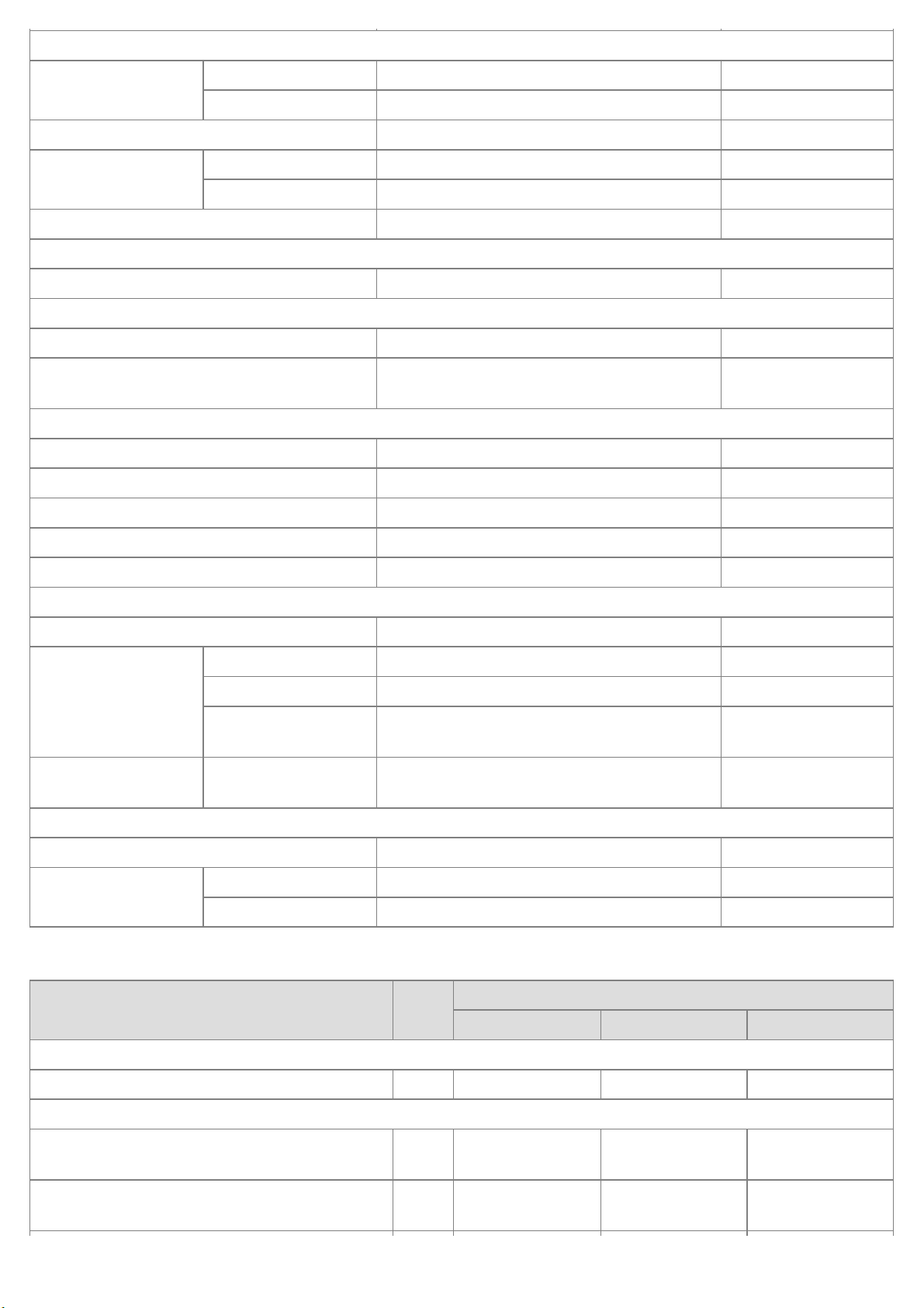
TIGHTENING TORQUE
Item
Quan-
tity
Tightening torque
N.m kgf.m lb-ft
Cylinder block
Engine support bracket bolts 8 36.3 ~ 53.9 3.7 ~ 5.5 26.8 ~ 39.8
Engine mounting
Engine mounting insulator and engine mounting
bracket fixing nuts
4 36.3 ~ 53.9 3.7 ~ 5.5 26.8 ~ 39.8
Engine support bracket and engine mounting
insulator fixing nuts
2 36.3 ~ 53.9 3.7 ~ 5.5 26.8 ~ 39.8
Page 5
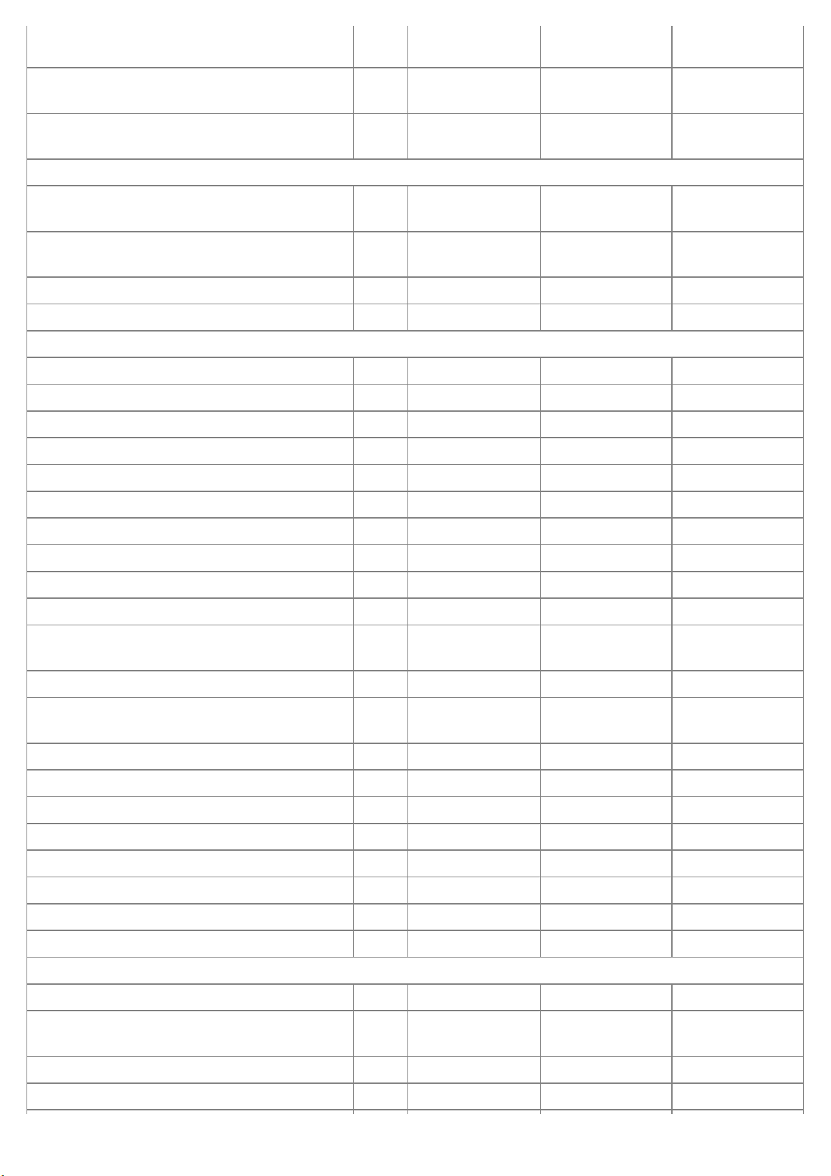
Transaxle mounting bracket and body fixing
bolts
4 36.3 ~ 53.9 3.7 ~ 5.5 26.8 ~ 39.8
Transaxle mounting insulator and transaxle
mounting bracket fixing bolt
1 62.8 ~ 93.2 6.4 ~ 9.5 46.3 ~ 68.7
Transaxle and transaxle mounting insulator
fixing nuts
4 36.3 ~ 53.9 3.7 ~ 5.5 26.8 ~ 39.8
Main moving system
Connecting rod cap nuts 8
68.6#Unfasten
bolts#29.4+90°
7.0 # Unfasten
bolts#3.0+ 90°
50.6# Unfasten
bolts#21.7+ 90°
Crankshaft main bearing cap bolts 10
(63.7 ~ 73.5) +
(105 + 115°)
(6.5 ~ 7.5) + (105
+ 115°)
(47.0 ~ 54.2) +
(105 + 115°)
Flywheel (DMF) bolts (M/T) 8 122.6 ~ 132.4 12.5 ~ 13.5 90.4 ~ 97.6
Drive plate bolts (A/T) 8 159.8 ~ 169.7 16.3 ~ 17.3 117.9 ~ 125.1
Timing belt
Timing belt upper cover bolts 5 6.9 ~ 9.8 0.7 ~ 1.0 5.1 ~ 7.2
Timing belt upper cover nut 1 6.9 ~ 9.8 0.7 ~ 1.0 5.1 ~ 7.2
Timing belt lower cover bolts 8 6.9 ~ 9.8 0.7 ~ 1.0 5.1 ~ 7.2
Crankshaft pulley bolt 1 372.7 ~ 411.9 38.0 ~ 42.0 274.9 ~ 303.8
Camshaft sprocket bolts 2 58.8 ~ 68.6 6.0 ~ 7.0 43.4 ~ 50.6
Timing belt tensioner bolt 1 20.6 ~ 25.5 2.1 ~ 2.6 15.2 ~ 18.8
Timing belt N0. 1 idler bolt 1 39.2 ~ 49.0 4.0 ~ 5.0 28.9 ~ 36.2
Timing belt N0. 2 idler bolt 1 37.3 ~ 43.1 3.8 ~ 4.4 27.5 ~ 31.8
Touch idler bolt 1 20.6 ~ 25.5 2.1 ~ 2.6 15.2 ~ 18.8
High pressure pump puli nut 1 58.8 ~ 68.6 6.0 ~ 7.0 43.4 ~ 50.6
High pressure pump and Timing belt case fixing
bolts
3 21.6 ~ 25.5 2.2 ~ 2.6 15.9 ~ 18.8
High pressure pump bracket bolts (Pump) 2 21.6 ~ 25.5 2.2 ~ 2.6 15.9 ~ 18.8
High pressure pump bracket bolts (Cylinder
block)
2 34.3 ~ 40.2 3.5 ~ 4.1 25.3 ~ 29.7
Timing belt plate bolts 6 7.8 ~ 11.8 0.8 ~ 1.2 5.8 ~ 8.7
Timing belt case bolts (8 X 25) 8 15.7 ~ 22.6 1.6 ~ 2.3 11.6 ~ 16.6
Timing belt case bolts (8 X 45) 2 15.7 ~ 22.6 1.6 ~ 2.3 11.6 ~ 16.6
Timing belt case bolts (8 X 50) 2 15.7 ~ 22.6 1.6 ~ 2.3 11.6 ~ 16.6
Timing belt case nut 1 15.7 ~ 22.6 1.6 ~ 2.3 11.6 ~ 16.6
Balancer gear bolt 1 63.7 ~ 73.5 6.5 ~ 7.5 47.0 ~ 54.2
Oil pump gear bolt 1 33.3 ~ 39.2 3.4 ~ 4.0 24.6 ~ 28.9
Idler gear bolt 1 33.3 ~ 39.2 3.4 ~ 4.0 24.6 ~ 28.9
Cylinder head
Cylinder head cover bolts 15 8.8 ~ -10.8 0.9 ~ -1.1 6.5 ~ -8.0
Rocker arm shaft And camshaft bearing cap
bolts
10 17.7 ~ 26.5 1.8 ~ 2.7 13.0 ~ 19.5
Camshaft bearing cap nuts 10 17.7 ~ 26.5 1.8 ~ 2.7 13.0 ~ 19.5
Front camshaft bearing cap nuts(Small nuts) 2 7.8 ~ 11.8 0.8 ~ 1.2 5.8 ~ 8.7
Page 6
Cylinder head bolt (Long bolts) 10 39.2 + 90° + 120° 4.0 + 90° + 120° 28.9 + 90° + 120°
Cylinder head bolt (Short bolts) 8 39.2 + 90°+ 90° 4.0 + 90° + 90° 28.9 + 90°+ 90°
Cooling system
Cooling fan water pump pulley bolts 4 5.9 ~ 9.8 0.6 ~ 1.0 4.3 ~ 7.2
Water pump bolt (Long bolts) 3 15.7 ~ 22.6 1.6 ~ 2.3 11.6 ~ 16.6
Water pump bolt (Short bolts) 2 15.7 ~ 22.6 1.6 ~ 2.3 11.6 ~ 16.6
Water pump and generator brace fixing bolts (8
X 45)
2 15.7 ~ 22.6 1.6 ~ 2.3 11.6 ~ 16.6
Thermostat housing and generator strip nuts 2 18.6 ~ 22.6 1.9 ~ 2.3 13.7 ~ 16.6
Thermostat case cover bolts 2 15.7 ~ 22.6 1.6 ~ 2.3 11.6 ~ 16.6
Lubrication system
Oil filter 1 21.6 ~ 24.5 2.2 ~ 2.5 15.9 ~ 18.1
Oil cooler bolts (8 X 35) 4 15.7 ~ 22.6 1.6 ~ 2.3 11.6 ~ 16.6
Oil cooler bolts (8 X 50) 4 15.7 ~ 22.6 1.6 ~ 2.3 11.6 ~ 16.6
Oil cooler nuts 2 15.7 ~ 22.6 1.6 ~ 2.3 11.6 ~ 16.6
Oil pan nuts 29 15.7 ~ 22.6 1.6 ~ 2.3 11.6 ~ 16.6
Oil pan drain plug 1 34.3 ~ 44.1 3.5 ~ 4.5 25.3 ~ 32.5
Ladder frame bolts (10 X 45) 5 31.4 ~ 46.1 3.2 ~ 4.7 23.1 ~ 34.0
Ladder frame and oil suppling pipe bolt (8X 50) 1 15.7 ~ 22.6 1.6 ~ 2.3 11.6 ~ 16.6
Ladder frame bracket (Oil pump and ladder
frame fixing) bolts
2 31.4 ~ 46.1 3.2 ~ 4.7 23.1 ~ 34.0
Oil supplying pipe and oil pump fixing bolts (8
X16)
2 15.7 ~ 22.6 1.6 ~ 2.3 11.6 ~ 16.6
Oil supplying pipe and Ladder frame fixing bolts
(8 X 16)
2 15.7 ~ 22.6 1.6 ~ 2.3 11.6 ~ 16.6
Oil pump bolts(10 X 60) 2 15.7 ~ 22.6 1.6 ~ 2.3 11.6 ~ 16.6
Oil pump bolt(8 X 30) 1 15.7 ~ 22.6 1.6 ~ 2.3 11.6 ~ 16.6
Oil screen nuts 2 15.7 ~ 22.6 1.6 ~ 2.3 11.6 ~ 16.6
Oil pressure switch 1 14.7 ~ 46.1 1.5 ~ 2.2 10.8 ~ 34.0
Intake and exhaust system
Intake manifold and cylinder head fixing bolts(8
X 45)
2 15.7 ~ 22.6 1.6 ~ 2.3 11.6 ~ 16.6
Intake manifold and cylinder head fixing bolts(8
X 95)
4 15.7 ~ 22.6 1.6 ~ 2.3 11.6 ~ 16.6
Intake manifold and cylinder head fixing nuts 2 15.7 ~ 22.6 1.6 ~ 2.3 11.6 ~ 16.6
Intake manifold and cylinder head fixing
hexagonal wrench bolt
1 17.7 ~ 26.5 1.8 ~ 2.7 13.0 ~ 19.5
Exhaust manifold and cylinder head fixing nut 9 26.5 ~ 34.3 2.7 ~ 3.5 19.5 ~ 25.3
Exhaust manifold heat cover and exhaust
manifold fixing bolts(6X12)
3 8.8 ~ 12.7 0.9 ~ 1.3 6.5 ~ 9.4
Engine hanger bracket and exhaust manifold
fixing bolts (8 X 18)
2 17.7 ~ 26.5 1.8 ~ 2.7 13.0 ~ 19.5
Exhaust manifold and front muffler fixing nut 2 39.2 ~ 58.8 4.0 ~ 6.0 28.9 ~ 43.4
Page 7

Front muffler CPF(Catalyzed Particulate Filter)
fixing nuts
2 39.2 ~ 58.8 4.0 ~ 6.0 28.9 ~ 43.4
CPF(Catalyzed Particulate Filter) main muffler
fixing nuts
2 39.2 ~ 58.8 4.0 ~ 6.0 28.9 ~ 43.4
Main muffler and tail pipe fixing nuts 2 39.2 ~ 58.8 4.0 ~ 6.0 28.9 ~ 43.4
Page 8
2009 > D 2.9 VGT >
INSPECTION
COMPESSION PRESSURE
If there is lack of power, excessive oil consumption or poor fuel economy, measure the compression pressure.
1. Warm up the engine until the coolant temperature becomes 80~95°C(176~203°F).
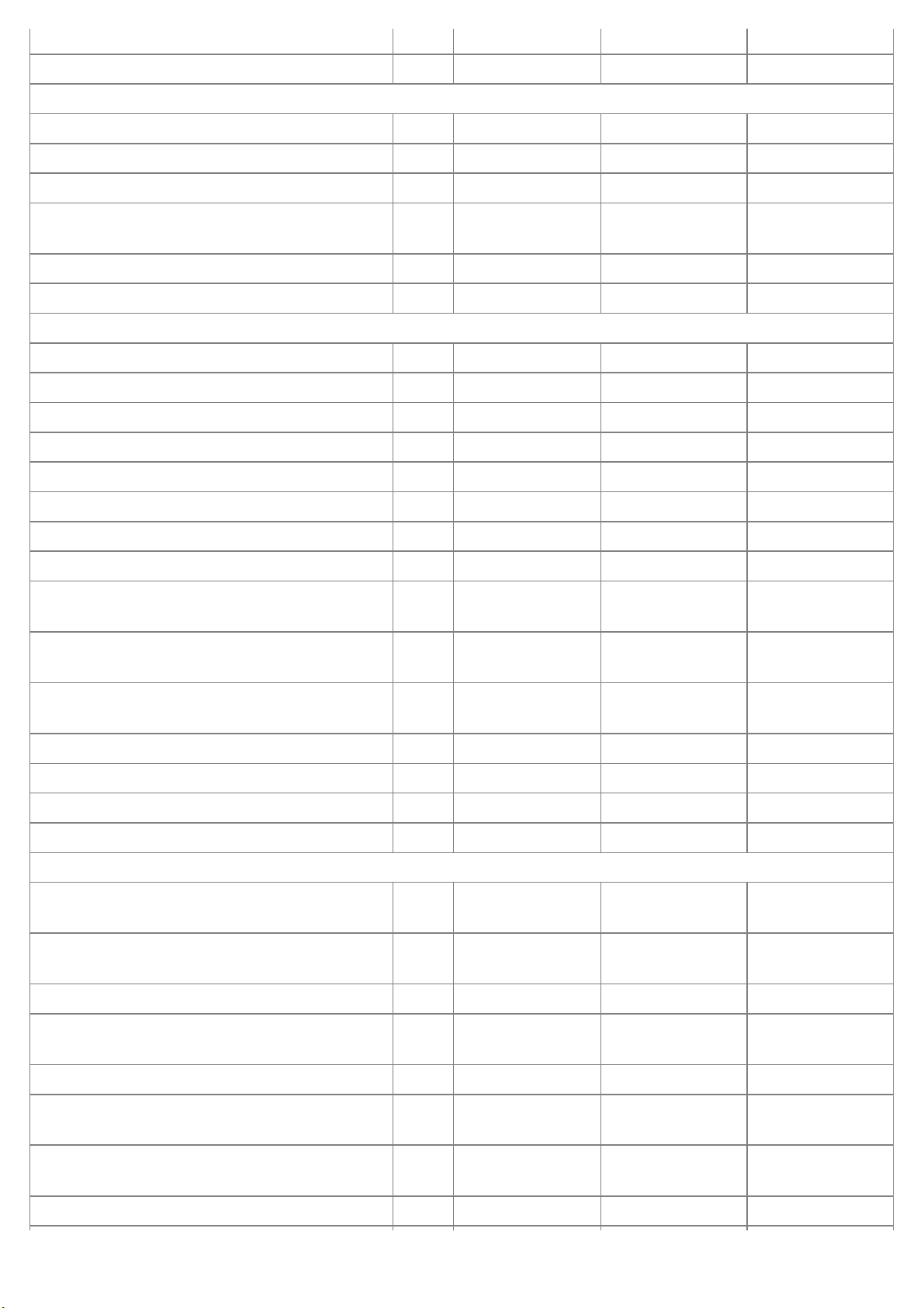
2. Remove the fuel inlet(A) and the return hose(B) from the fuel filter.
3. Crank the engine in order to exhaust fuel in the high pressure pump.
Gather residual fuel by putting the return hose into a proper vessel.
4. Remove the injection pipe, injector and washer.(Refer to FL group).
5. Measure the cylinder compression pressure.
(1) Insert the SST(0K552 131 002) into the injector hole.
(2) Cranking the engine, measure the pressure.
Use the complete charging battery for the engine to crank at the speed of 350rpm or more.
(3) Do the above step 1)~2) again for each cylinder.
This work must be done in as short time as possible.
Compression pressure :
3040.05kPa (31kg/cm!, 440.92psi) (325 rpm)
Minimum pressure :
2745.85kPa (28kg/cm!, 398.25psi)
Difference between each cylinder :
294.20kPa (3.0kg/cm!, 42.67psi)
(4) If, in one or more cylinders, the measured value is below the limit, fill a little engine oil into the injector holes of
the cylinders, repeat the step 1)~2) and measure the compression pressure again.
A. If the re-measured pressure becomes higher, wear or damage of the piston ring or cylinder surface can be
the cause.
B. If the re-measured pressure does not become higher, adherence or poor contact of the valves or inferior
Page 9
gasket can be the cause.
6. Install the injectors, washers and the injector pipes.(Refer to FL group).
7. Install the inlet and the return hoses to the fuel filter.
TIMING BELT TENSION ADJUSTMENT
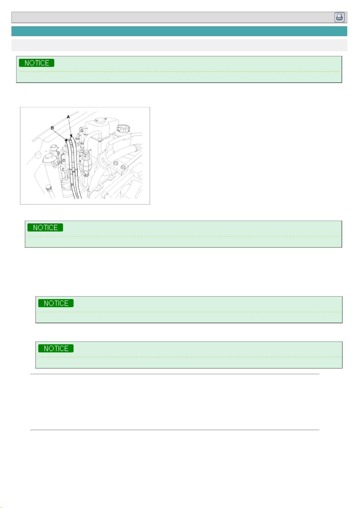
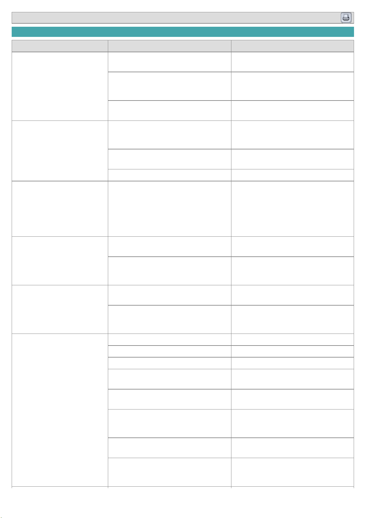
1. Remove the battery terminals (A).
2. Install the jack for oil pan.
3. Remove the engine mounting (A).
4. Remove the engine support bracket(A).
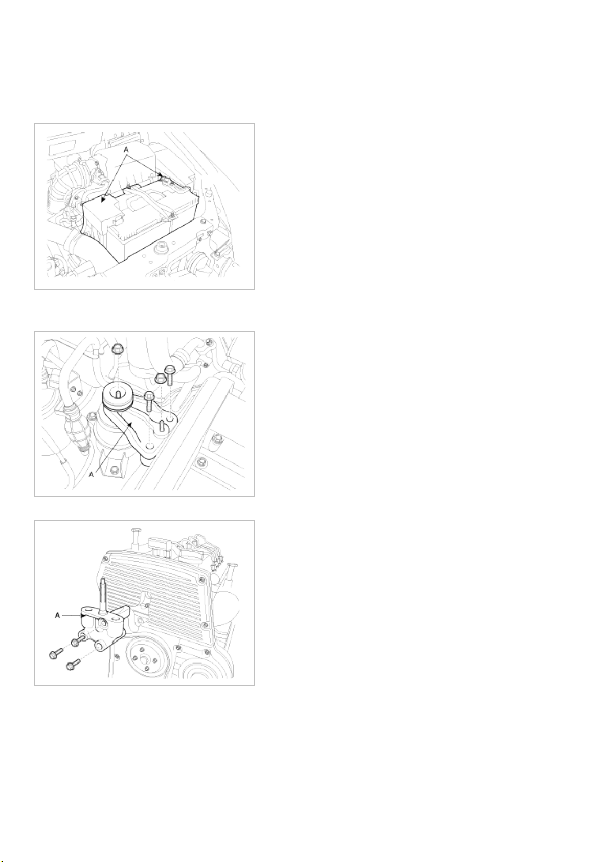
5. Remove the drive belt.
Page 10
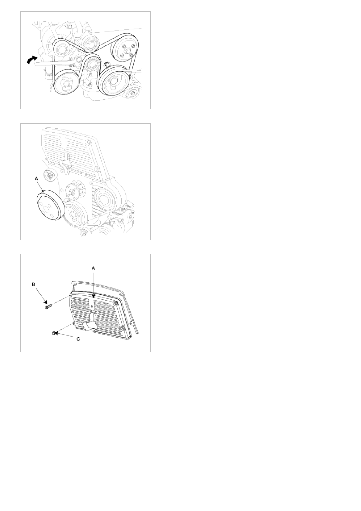
6. Remove the water pump pulley.
7. Remove the bolts(B), nut(C) and timing belt upper cover (A).
8. Turn the crankshaft pulley(A) and align its groove with the timing mark “T” of the timing belt cover. Check that the
timing mark of camshaft sprocket(B) is aligned with that of the cylinder head cover. (No.1 cylinder positioned at the
TDC position)
Page 11

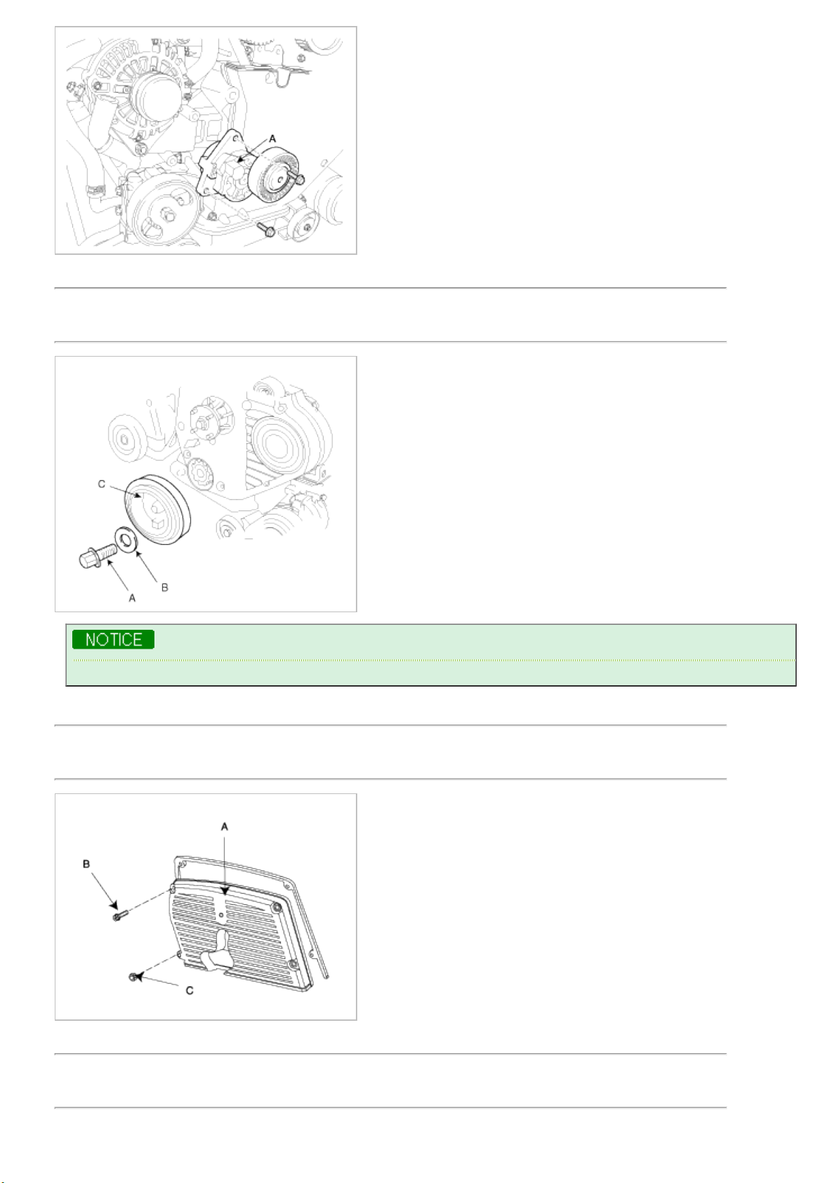
9. Remove the crankshaft pulley bolt(A), washer(B) and crankshaft pulley(C).
Using the special tool(09517-21700, 09231-H1000), fix the crankshaft pulley and loosen the bolt(A).
10. Remove the drive belt idler(A).
Page 12
11. Remove the drive belt auto-tensioner (A).
12. Remove the timing belt lower cover(A).
13. Loosen the auto-tensioner fixing bolt(A).
Page 13

14. Adjust tension of the timing belt.
(1) Align the pointer(B) with the tensioner fork(back plate)(C) as shown below by turning the special washer(A)
counterclockwise with a hexagonal wrench.
(2) When the pointer(A) is aligned with the tensioner fork(back plate)(B), tighten the tensioner mounting bolts with
the special bolt fixed by a hexagonal wrench.
Tightening torque :
19.6~25.5Nm (2.0~2.6kgf.m, 14.5~18.8lb-ft)
(3) Remove the hexagonal wrench.
When the pointer (A) can not be aligned with the tensioner fork(back plate)(B), replace a new belt and
repeat the steps.
15. Rotate the crankshaft clockwise two revolutions in order to align the timing marks on the crankshaft sprocket, the
camshaft sprocket and high pressure pump pulley.
16. Confirm that the location of the pointer is aligned with tensioner fork (back plate).
The margin of error : ± 5°
Page 14
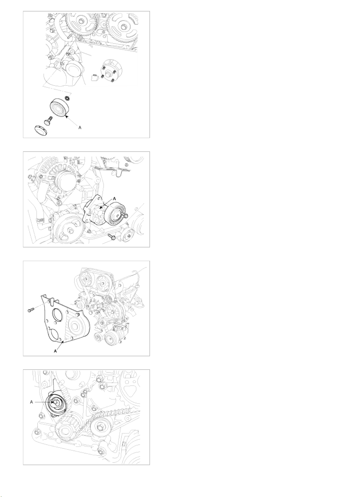
17. Install the timing belt lower cover(A).
Tightening torque :
6.9~9.8Nm (0.7 ~ 1.0kgf.m, 5.1 ~ 7.2lb-ft)
18. Install the drive belt idler(A).
Tightening torque :
37.3Nm (3.8kgf.m, 27.5lb-ft)
19. Install the drive belt auto-tensioner (A).
Tightening torque :
15.7~22.6Nm (1.6 ~ 2.3kgf.m, 11.6 ~ 16.6lb-ft)
Page 15
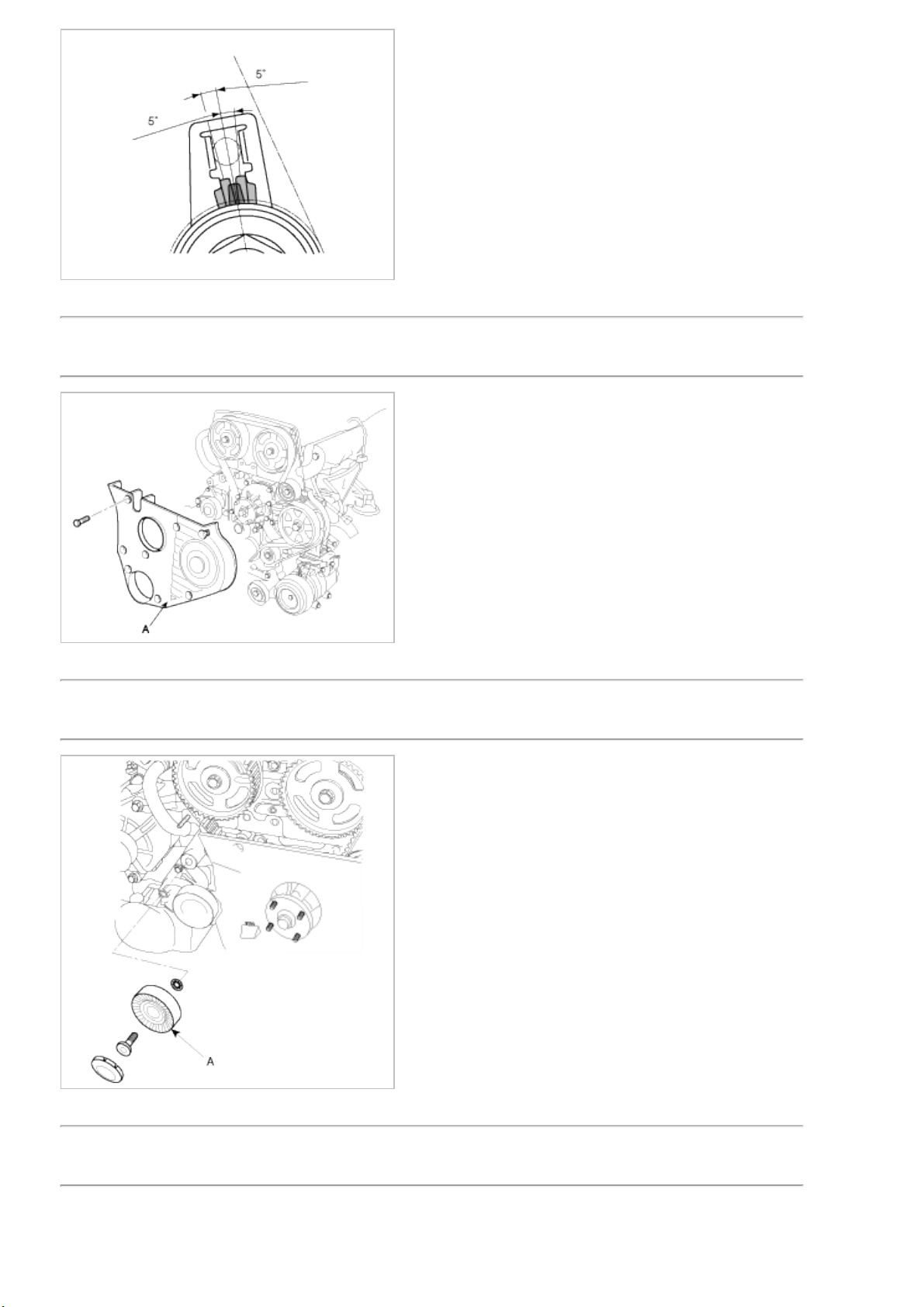
20. Install the crankshaft pulley bolt(A), washer(B) and crankshaft pulley (A).
Tightening torque :
376.6~411.9Nm (38.4~42.0kgf.m, 277.7~303.8lb-ft)
Using the special tool(09517-21700, 09231-H1000), tighten the bolt(A).
21. Install the bolts(B), nut(C) and timing belt upper cover (A).
Tightening torque :
6.9~9.8Nm (0.7 ~ 1.0kgf.m, 5.1 ~ 7.2lb-ft)
22. Install the water pump pulley.
Tightening torque :
5.9~9.8Nm (0.6 ~ 1.0kgf.m, 4.3 ~ 7.2lb-ft)
Page 16
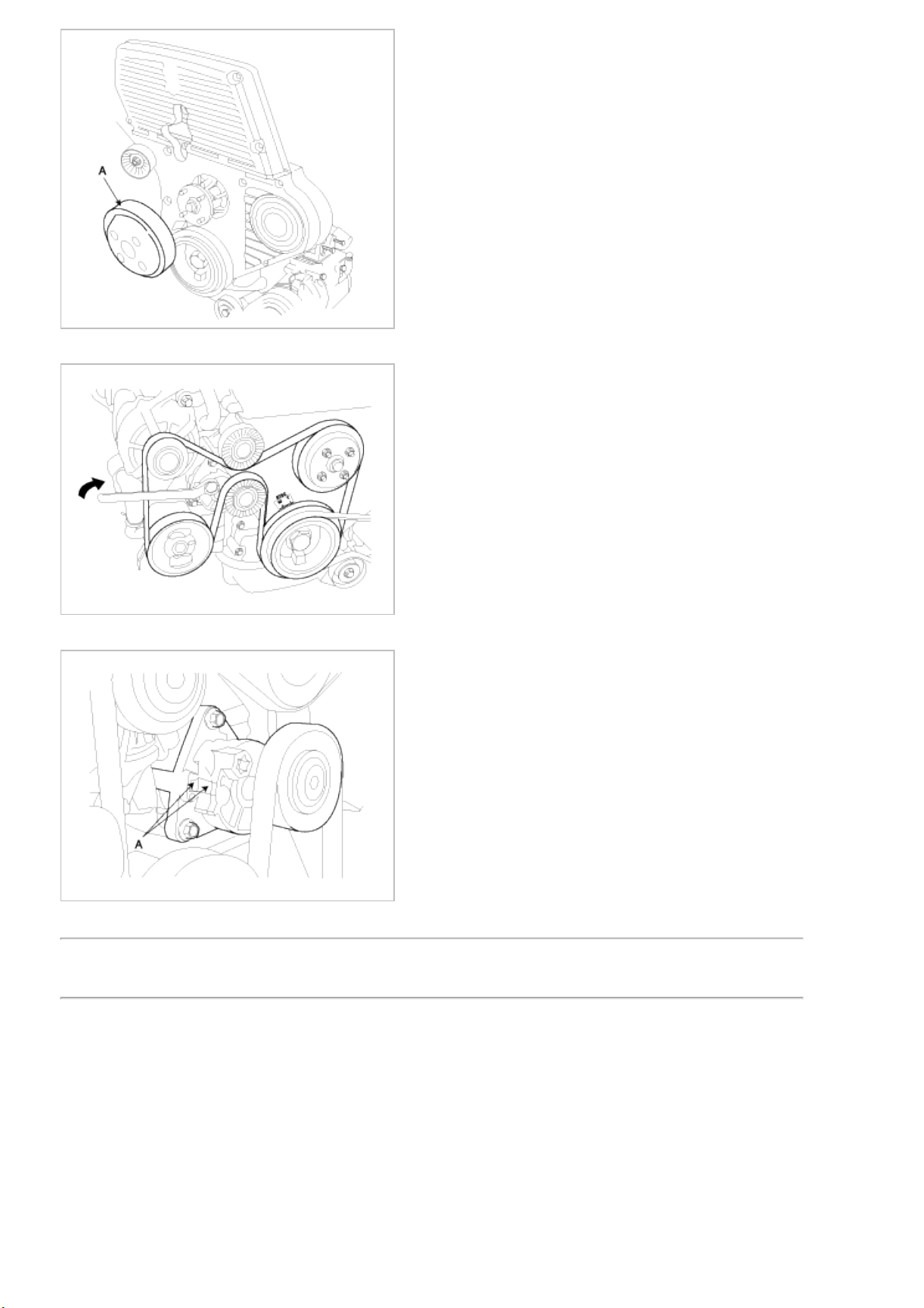
23. Install the drive belt.
24. Confirm that the 'A' part of the drivebelt auto-tensioner is positioned as shown below. If not, replace the belt.
25. Install the engine support bracket(A).
Tightening torque :
49.0~63.7Nm (5.0 ~ 6.5kgf.m, 36.2 ~ 47.0lb-ft)
Page 17
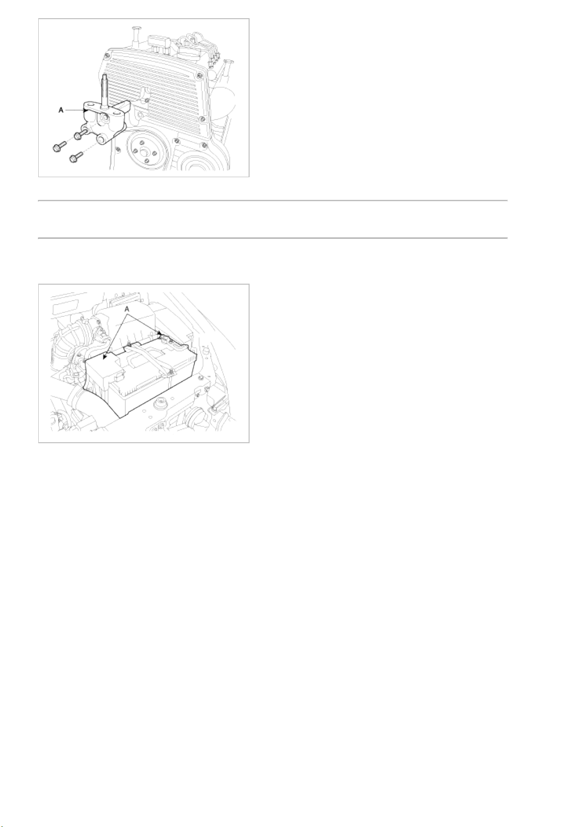
26. Install the engine mounting (A).
Tightening torque :
88.3~107.9Nm (9.0 ~ 11.0kgf.m, 65.1 ~ 79.6lb-ft)
27. Remove the jack for oil pan.
28. Install the battery terminals (A).
Page 18
2009 > D 2.9 VGT >
TROUBLESHOOTING
Symptom Suspect area Remedy
Engine misfire with abnormal
internal lower engine noises.
Loose or improperly installed engine
flywheel.
Repair or replace the flywheel as
required.
Worn piston rings.
(Oil consumption may or may not cause
the engine to misfire.)
Inspect the cylinder for a loss of
compression .
Repair or replace as required.
Worn crankshaft thrust bearings. Replace the crankshaft and bearings as
required.
Engine misfire with abnormal
valve train noise.
Stuck valves.
(Carbon buildup on the valve stem can
cause the valve not to close properly.)
Repair or replace as required.
Excessive worn or mis-aligned timing
chain.
Replace the timing chain and sprocket
as required.
Worn camshaft lobes. Replace the camshaft and valve lifers.
Engine misfire with coolant
consumption
• Faulty cylinder head gasket and/or
cracking or other damage to the
cylinder head and engine block
cooling system .
• Coolant consumption may or may not
cause the engine to overheat.
• Inspect the cylinder head and engine
block for damage to the coolant
passages and/or a faulty head
gasket.
• Repair or replace as required.
Engine misfire with excessive
oil consumption
Worn valves, valve guides and/or valve
stem oil seals.
Repair or replace as required.
Worn piston rings.
(Oil consumption may or may not cause
the engine to misfire)
Inspection the cylinder for a loss of
compression
Repair or replace as required.
Engine noise on start-up, but
only lasting a few seconds.
Incorrect oil viscosity. Drain the oil.
Install the correct viscosity oil.
Worn crankshaft thrust bearing. Inspect the thrust bearing and
crankshaft.
Repair or replace as required.
Upper engine noise, regardless
of engine speed.
Low oil pressure. Repair or replace as required.
Broken valve spring. Replace the valve spring.
Worn or dirty valve lifters. Replace the valve lifters.
Stretched or broken timing chain and/or
damaged sprocket teeth.
Replace the timing chain and sprockets.
Worn timing chain tensioner, if
applicable.
Replace the timing chain tensioner as
required.
Worn camshaft lobes. Inspect the camshaft lobes.
Replace the camshaft and valve lifters as
required.
Worn valve guides or valve stems. Inspect the valves and valve guides, then
repair as required.
Stuck valves. (Carbon on the valve stem
or valve seat may cause the valve to
stay open.)
Inspect the valves and valve guides, then
repair as required.
Page 19
Lower engine noise, regardless
of engine speed.
Low oil pressure. Repair or replace damaged components
as required.
Loose or damaged flywheel. Repair or replace the flywheel.
Damaged oil pan, contacting the oil
pump screen.
Inspect the oil pan.
Inspect the oil pump screen.
Repair or replace as required.
Oil pump screen loose, damaged or
restricted.
Inspect the oil pump screen .
Repair or replace as required.
Excessive piston-to-cylinder bore
clearance.
Inspect the piston and cylinder bore.
Repair as required.
Excessive piston pin-to-bore clearance. Inspect the piston, piston pin and the
connecting rod.
Repair or replace as required.
Excessive connecting rod bearing
clearance.
Inspect the following components and
repair as required.
• The connecting rod bearings.
• The connecting rods.
• The crankshaft.
• The crankshaft journal.
Excessive crankshaft bearing clearance. Inspect the following components and
repair as required.
• The crankshaft bearings.
• The crankshaft journals.
Incorrect piston, piston pin and
connecting rod installation.
Verify the piston pins and connecting
rods are installed correctly.
Repair as required.
Engine noise under load. Low oil pressure. Repair or replace as required.
Excessive connecting rod bearing
clearance.
Inspect the following components and
repair as required.
• The connecting rod bearings.
• The connecting rods.
• The crankshaft.
Excessive crankshaft bearing clearance. Inspect the following components and
repair as required.
• The crankshaft bearings.
• The crankshaft journals.
• The cylinder block crankshaft bearing
bore.
Engine will not crank.
(crankshaft will not rotate)
Hydraulically locked cylinder.
• Coolant/antifreeze in cylinder.
• Oil in cylinder.
• Fuel in cylinder.
Remove spark plugs and check for fluid.
Inspect for broken head gasket.
Inspect for cracked engine block or
cylinder head.
Inspect for a sticking fuel injector and/or
leaking fuel regulator.
Broken timing chain and/or timing chain
gears.
Inspect timing chain and gears.
Repair as required.
Foreign material in cylinder.
• Broken valve.
• Piston material.
• Foreign material.
Inspect cylinder for damaged
components and/or foreign materials.
Repair or replace as required.
Page 20

Seized crankshaft or connecting rod
bearings.
Inspect crankshaft and connecting rod
bearing.
Repair or replace as required.
Bent or broken connecting rod. Inspect connecting rods.
Repair or replace as required.
Broken crankshaft. Inspect crankshaft.Repair or replace as
required.
Page 21
2009 > D 2.9 VGT >
SPECIAL SERVICE TOOLS
Tool (Number and name) Illustration Use
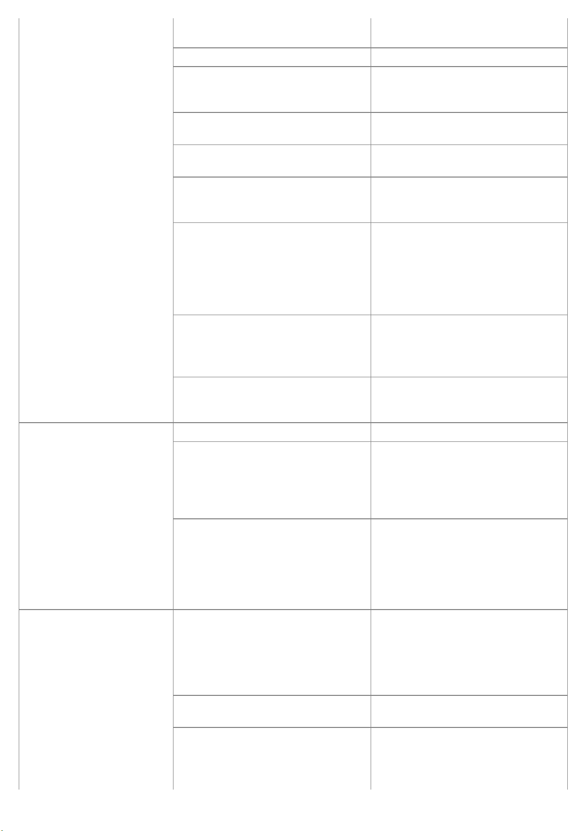
Valve spring lifter pivot.
(0K993 120 004)
Removal or installation of the valve spring
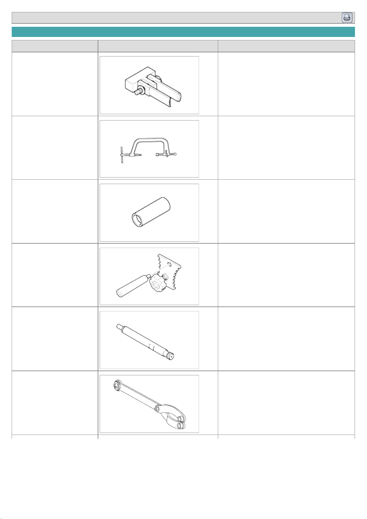
Valve spring lifter arm.
(0K993 120 001)
Removal or installation of the valve spring
Valve seal installer.
(09222-22001)
Installation of the valve seal
Camshaft pulley holder.
(09231 - 4X100)
Installation of the camshaft
Pressure gauge adapter.
(0K552 131 002)
Measurement of compression pressure
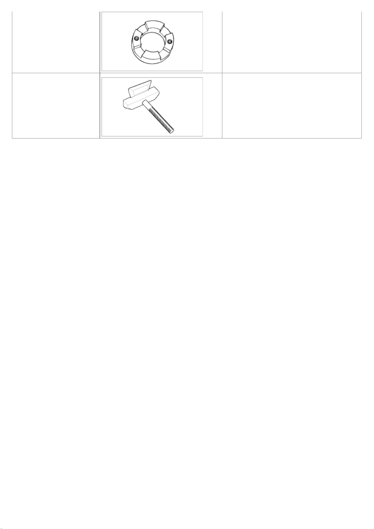
End york holder.
(09517-21700)
Removal or installation of the crankshaft
pulley bolt
(used with 09231-H1000)
Page 22
Crankshaft pulley adapter.
(09231-H1000)
Removal or installation of the crankshaft
pulley bolt
(used with 09517-21700)
Oil pan remover.
(09215-3C000)
Removal of the oil pan
Page 23

Engine Mechanical System
Timing System - Timing Belt
Engine Mechanical System
Page 24
2009 > D 2.9 VGT >
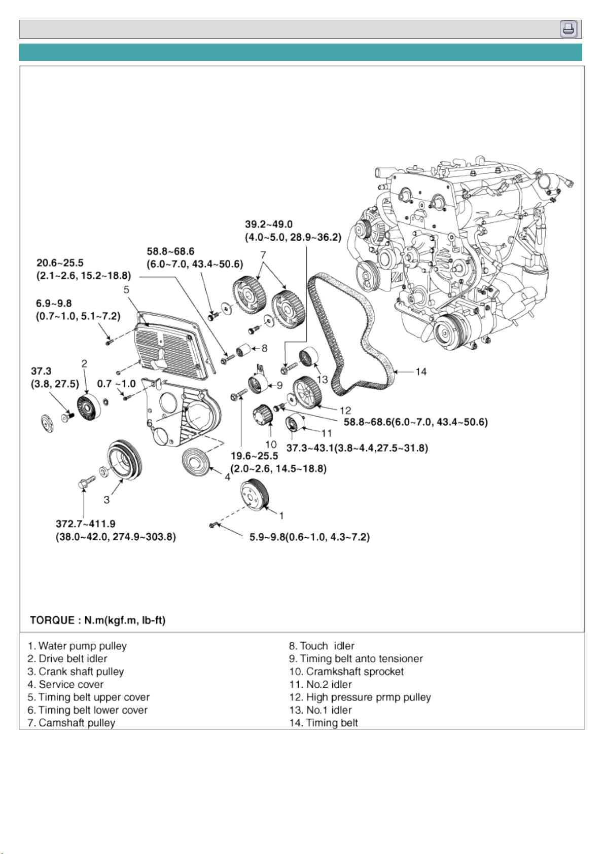
COMPONENTS
Page 25
2009 > D 2.9 VGT >
REMOVAL
Engine removal is not required for this procedure.
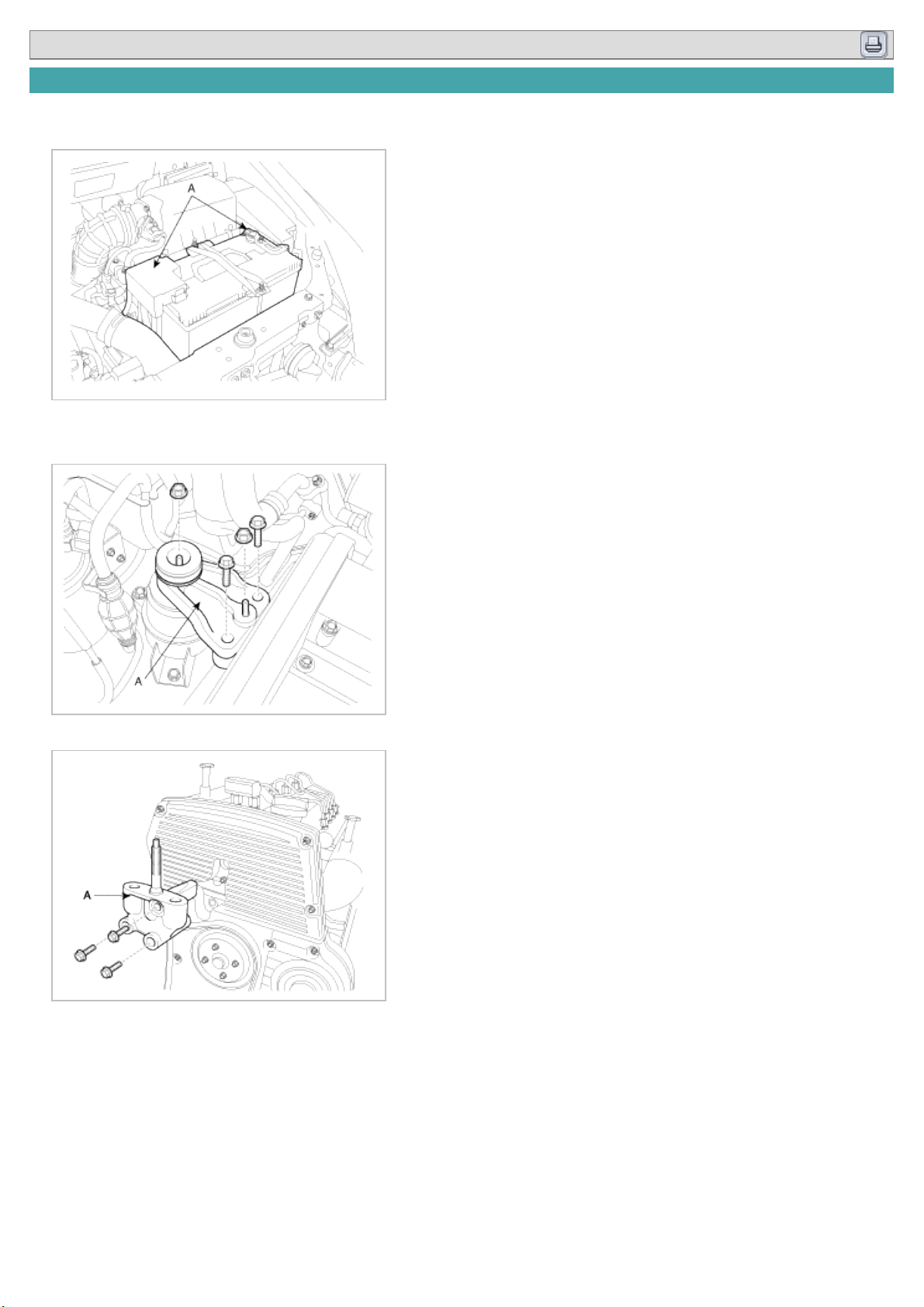
1. Remove the battery terminals (A).
2. Install the jack for oil pan.
3. Remove the engine mounting (A).
4. Remove the engine support bracket(A).
5. Remove the drive belt.
Page 26

6. Remove the water pump pulley.
7. Remove the bolts(B), nut(C) and timing belt upper cover (A).
8. Turn the crankshaft pulley(A), and align its groove with timing mark “T” of the timing belt cover. Check that the
timing mark of camshaft sprocket(B) is aligned with the timing mark of cylinder head cover. (No.1 cylinder
compression TDC position)
Page 27
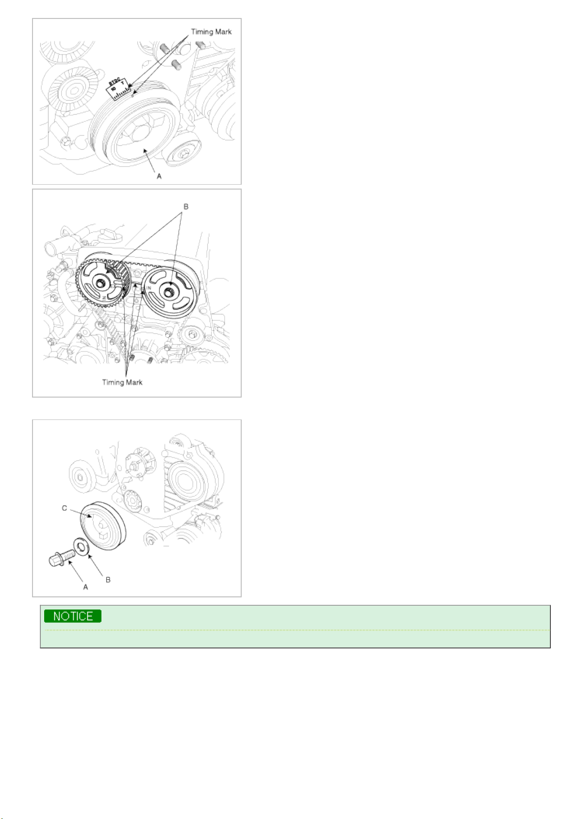
9. Remove the crankshaft pulley bolt(A), washer(B) and crankshaft pulley (C).
Using the special tool(09517-21700, 09231-H1000), fix the crankshaft pulley and loosen the bolt(A).
10. Remove the drive belt idler(A).
Page 28
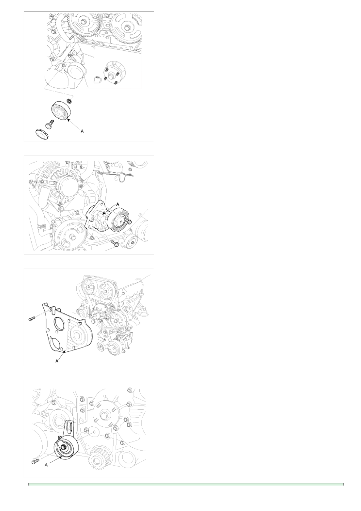
11. Remove the drive belt auto-tensioner (A).
12. Remove the timing belt lower cover(A).
13. Remove the auto-tensioner(A) with the timing belt.
Page 29
In reusing the timing belt, install the belt with the arrow mark facing to rotating direction.
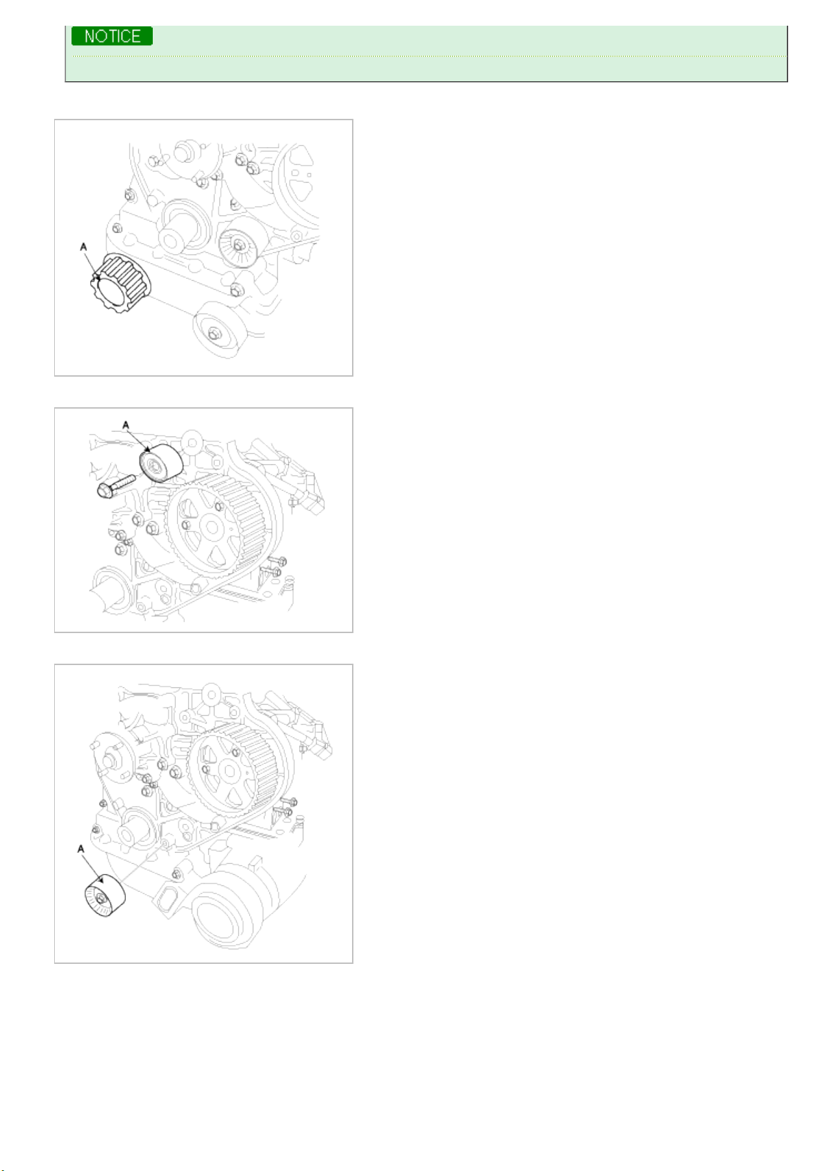
14. Remove the timing belt sprocket(A).
15. Remove the timing belt No.1 idler(A).
16. Remove the timing belt No.2 idler(A).
17. Remove the touch idler(A).
Page 30
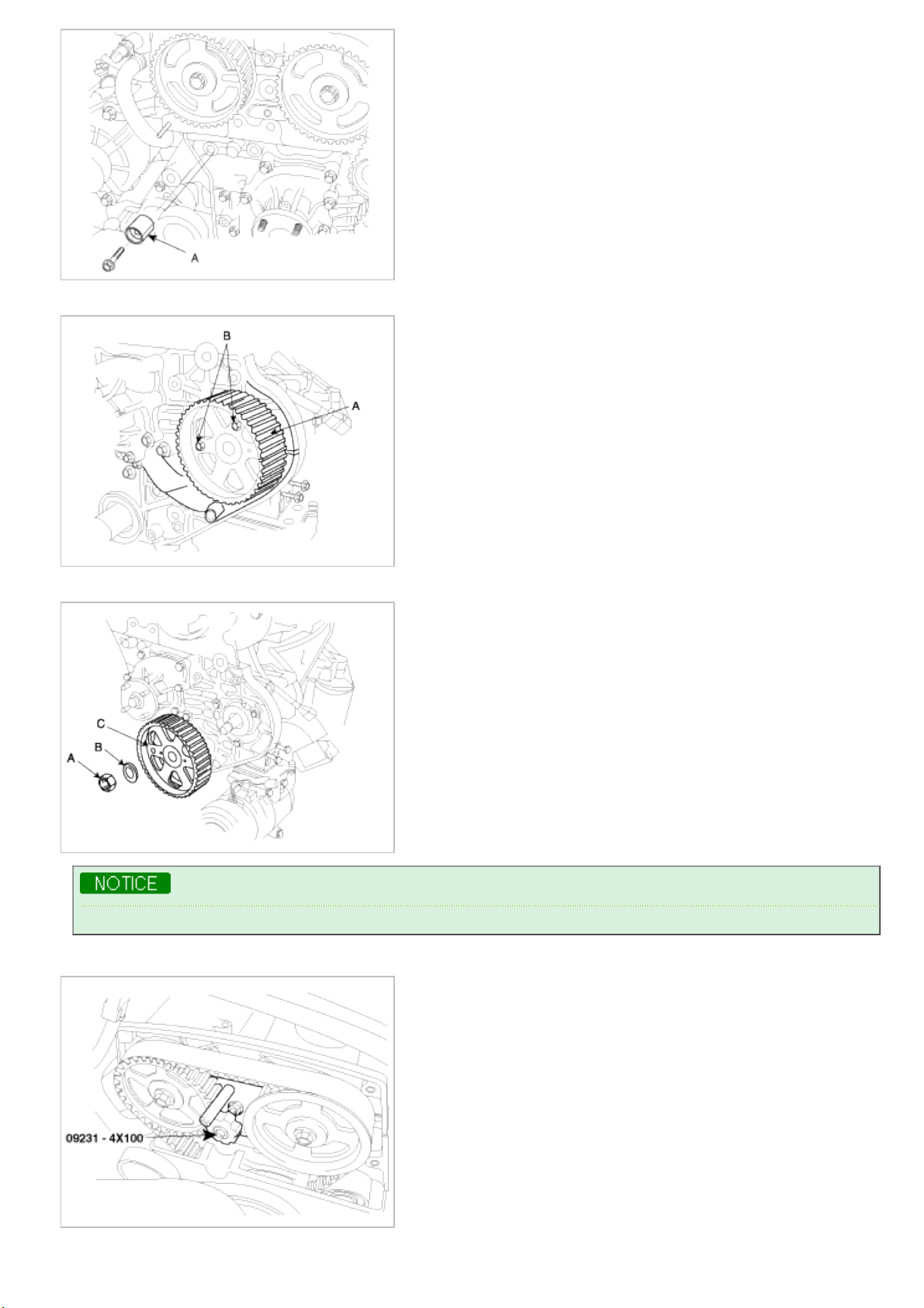
18. Fix the high pressure pump pulley, using the setting bolt(B) for the pulley not to be rotated.
19. Remove the high pressure pulley nut(A), with the washer(B), pulley(C).
Using SST, remove the pulley. (Refer to FL group).
20. Using SST(09231-4X100), remove the camshaft pulley.
Page 31

INSPECTION
SPROCKETS, TENSIONER, IDLER
1. Check the camshaft sprocket, crankshaft sprocket, tensioner pulley, and idler pulley for abnormal wear, cracks, or
damage. Replace as necessary.
2. Inspect the tensioner pulley and the idler pulley for easy and smooth rotation and check for play or noise. Replace
as necessary.
3. Replace the pulley if there is a grease leak from its bearing.
TIMING BELT
1. Check the belt for oil or dust deposits.
Replace, if necessary.
Small deposits should be wiped away with a dry cloth or paper. Do not clean with solvent.
2. When the engine is overhauled or belt tension adjusted, check the carefully. If any of the following flaws are
evident, replace the belt.
• Do not bend, twist or turn the timing belt inside out.
• Do not allow timing belt to come into contact with oil, water and steam.
INSTALLATION
1. Using SST (09231-4X100), install the camshaft pulley.
Tightening torque :
58.8~68.6Nm (6.0~7.0kgf.m, 43.4 ~ 50.6lb-ft)
2. After installing the high pressure pump pulley(A), tighten the high pressure pump pulley nut with the setting bolt(B)
for the pulley not to be rotated.
Tightening torque :
Page 32

58.8~68.6Nm (6.0~7.0kgf.m, 43.4 ~ 50.6lb-ft)
3. Install the touch idler(A).
Tightening torque :
7.8 ~ 9.8Nm (2.1~2.6kgf.m, 5.8 ~ 7.2lb-ft)
4. Install the timing belt No.2 idler(A).
Tightening torque :
7.8 ~ 9.8Nm (3.8~4.4kgf.m, 5.8 ~ 7.2lb-ft)
Ensure the location of idlers.
No.1 idler : 60mm(2.3622in)
No.2 idler : 55mm(2.1654in)
Page 33

5. Install the timing belt No.1 idler(A).
Tightening torque :
7.8 ~ 9.8Nm (4.0~5.0kgf.m, 5.8 ~ 7.2lb-ft)
6. Install the timing belt sprocket(A).
7. Check that the timing mark of camshaft pulley(A), high pressure pump pulley(B) and crankshaft pulley(c).
Page 34

8. Install the timing belt.
Crankshaft sprocket pulley(A)!No.2 idler(B)!High pressure pump pulley (C) ! No.1 idler(D) ! camshaft sprocket
pulley (E)
Because the auto-tensioner should be installed after the timing belt, be careful about the tension of the belt
before the installation of the auto-tensioner.
Page 35

9. Install the auto-tensioner as shown below which the tensioner fork(back plate)(A) positioned around the dowel
pin(B).
Be careful for the auto-tensioner not to be stained with oil. If so, replace the auto-tensioner with a new one.
The location of the pointer, the back plate and the special washer is as shown.
10. Adjust the tension of the timing belt.
(1) Adjust the location of the pointer (B) aligning the tensioner fork(back plate)(C) as shown below by turning the
special washer(A) counterclockwise with a hexagonal wrench.
(2) When aligning the pointer(A) with the tensioner fork(back plate)(B), tighten the tensioner mounting bolt with
fixing the special washer not to move by a hexagonal wrench.
Tightening torque :
19.6~25.5Nm (2.0~2.6kgf.m, 14.5~18.8lb-ft)
Page 36

(3) Remove the hexagonal wrench.
If the pointer is not aligned with the tensioner fork(back plate), replace the belt with a new one and adjust
them again.
11. Align the timing marks of the crankshaft sprocket, the camshaft sprocket and the high pressure pump pulley by
turning the crankshaft clockwise two revolutions.
12. Check that the location of the pointer is aligned with the tensioner fork (back plate).
The margin of error : ± 5°
If the location of the pointer is not within the margin of error, repeat the steps 10)~12).
13. Install the timing belt lower cover(A).
Tightening torque :
6.9~9.8Nm (0.7 ~ 1.0kgf.m, 5.1 ~ 7.2lb-ft)
Page 37

14. Install the drive belt idler(A).
Tightening torque :
37.3Nm (3.8kgf.m, 27.5lb-ft)
15. Install the drive belt auto-tensioner (A).
Tightening torque :
15.7~22.6Nm (1.6 ~ 2.3kgf.m, 11.6 ~ 16.6lb-ft)
16. Install the crankshaft pulley bolt(A), washer(B) and crankshaft pulley (A).
Tightening torque :
376.6~411.9Nm (38.4~42.0kgf.m, 277.7~303.8lb-ft)
Page 38

Using the special tool(09517-21700, 09231-H1000).
17. Install the bolts(B), nut(C) and timing belt upper cover (A).
Tightening torque :
6.9~9.8Nm (0.7 ~ 1.0kgf.m, 5.1 ~ 7.2lb-ft)
18. Install the water pump pulley.
Tightening torque :
5.9~9.8Nm (0.6 ~ 1.0kgf.m, 4.3 ~ 7.2lb-ft)
19. Install the drive belt.
Page 39

20. Check that the 'A' part of the drivebelt auto-tensioner is aligned as shown below. If not, replace the drivebelt.
21. Install the engine support bracket(A).
Tightening torque :
49.0~63.7Nm (5.0 ~ 6.5kgf.m, 36.2 ~ 47.0lb-ft)
22. Install the engine mounting (A).
Tightening torque :
88.3~107.9Nm (9.0 ~ 11.0kgf.m, 65.1 ~ 79.6lb-ft)
Page 40

23. Remove the jack for oil pan.
24. Install the battery terminals (A).
Page 41

Engine Mechanical System
Cylinder Head Assembly
Engine Mechanical System
Page 42

2009 > D 2.9 VGT >
COMPONENTS
Page 43

2009 > D 2.9 VGT >
REMOVAL
Engine removal is not required for this procedure.
• To avoid damaging the cylinder head, wait until the engine coolant temperature drops below normal
temperature before removing it.
• When handling a metal gasket, take care not to fold the gasket or damage the contact surface of the gasket.
• To avoid damage, unplug the wiring connectors carefully while holding the connector portion.
• Mark all wiring and hoses to avoid misconnection.
• Inspect the timing belt before removing the cylinder head.
• Turn the crankshaft pulley so that the No. 1 piston is at top dead center.
1. Remove the battery(A).
2. Drain the engine coolant.
Remove the radiator cap to speed draining.
3. Remove the intake air hose and air cleaner assembly.
(1) Disconnect the AFS(Air Flow Sensor) connector(A).
(2) Disconnect the air cleaner upper cover(A).
Page 44

(3) Remove the air cleaner assembly(A).
(4) Remove the air intake hose(A).
4. Remove the radiator upper hose(A).
5. Remove the reservoir tank hose(A).
Page 45

6. Remove the PCV(Positive Crankcase Ventilation) hose(A), EGR valve vacuum hose(B), EGR cooler water hose(C),
pump vacuum oil hose(D).
7. Remove the intercooler hose(A,C), pipe(B).
8. Remove the wiring connectors and clamps from cylinder head and intake manifold.
(1) Remove the generator connector (A) and ETC(Engine Coolant Temperature) sensor connector (B).
Page 46

(2) Remove the injector connector(A), common rail pressure sensor connector(B), wire harness protector(C).
(3) Remove the ground cable(A) from cylinder head.
(4) Remove the knock sensor connector (A), high pressure pump fuel hose (B), high pressure pump connector(C).
(5) Remove the air conditioner condenser (A).
Page 47

(6) Remove the oil pressure switch connector (A).
(7) Remove the air heater (A), CMP (Camshaft Position Sensor) connector (B).
9. Remove the injection pipe, injector. (Refer to FL- injector.)
10. Remove the exhaust manifold.
11. Remove the intake manifold.
12. Remove the timing belt.
13. Remove the hose(C, D) and pipe (E) from. the ventilation housing(A) and the air separator(B).
Page 48

14. Remove the oil pipe (B) and hose(C) from the generator vacuum pump (A).
15. Remove the generator fixing bolts(B,C), nuts(D) and then the generator(A).
16. After removing the water hose(C) from the thermostat housing (B), remove the generator fixing bracket (A) and
the thermostat housing (B).
17. Remove the cylinder head cover(A).
Page 49

18. Remove the timing belt plate(A).
19. Remove the rockerarm shaft(A).
20. Remove the camshaft bearing caps(A).
Page 50

21. Remove the camshaft(A).
22. Remove the cylinder head bolts, then remove the cylinder head.
(1) Remove the 18 cylinder head bolts, in several steps and the sequence shown below.
Head warpage or cracking could result from removing bolts in an incorrect order.
(2) Lift the cylinder head from the dowels on the cylinder block and replace the cylinder head on wooden blocks
on a bench.
Be careful not to damage the contact surfaces of the cylinder head and cylinder block.
DISASSEMBLY
1. Remove the valves.
(1) Using the SST (0K9993 120 004, 0K993 120 001), compress the valve spring and remove the retainer lock.
(2) Remove the spring retainer.
Page 51

(3) Remove the valve spring.
(4) Remove the valve.
(5) Using a needle-nose pliers, remove the oil seal.
(6) Using a magnetic finger, remove the spring seat.
INSPECTION
CYLINDER HEAD
1. Inspect for flatness.
Using a precision straight edge and feeler gauge, measure the surface the contacting the cylinder block and the
manifolds for warpage.
Flatness of cylinder head gasket surface
Less than 0.05mm (0.0020in)
Flatness of manifold mating surface
Less than 0.15mm (0.0059in)
2. Inspect for cracks.
Check the combustion chamber, intake ports, exhaust ports and cylinder block surface for cracks. If cracked,
replace the cylinder head.
VALVE AND VALVE SPRING
1. Inspect the valve stems and valve guides.
(1) Using a caliper gauge, measure the innner diameter of valve guide.
Valve guide inner diameter :
7.010~7.030mm (0.2760~0.2768in)
Page 52

(2) Using a micrometer, measure the outer diameter of valve stem.
Valve stem outer diameter
Intake : 6.965~6.980mm (0.2742~0.2748in)
Exhaust : 6.945~6.960mm (0.2734~0.2740in)
(3) Subtract the valve stem outer diameter measurement from the valve guide innner diameter measurement.
Valve stem- to-guide clearance
Intake : 0.030 ~ 0.065mm (0.0012 ~ 0.0026in)
Exhaust : 0.050 ~ 0.085mm (0.0020 ~ 0.0033in)
If the clearance is greater than maximum, replace the valve and valve guide.
2. Inspect the valves.
(1) Check the valve is ground to the correct valve face angle.
(2) Check that the surface of valve for wear.
If the valve face is worn, replace the valve.
(3) Check the valve head margin thickness.
If the margin thickness is less than minimum, replace the valve.
Margin
Intake : 1.7mm (0.0669in)
Exhaust : 1.6mm (0.0630in)
(4) Check the surface of valve stem tip for wear.
If the valve stem tip is worn, replace the valve.
3. Inspect the valve seats.
(1) Check the valve seat for evidence of overheating and improper contact with the valve face.
Replace the seat if necessary.
(2) Before reconditioning the seat, check the valve guide for wear. If the valve guide is worn, replace it, then
Page 53

recondition the seat.
(3) Recondition the valve seat with a valve seat grinder or cutter. The valve seat contact width should be within
4. Inspect the valve springs.
(1) Using a steel square, measure the out -of-square of valve spring.
(2) Using a vernier calipers, measure the free length of valve spring.
Valve spring
Free height : 52.477mm (2.0660in)
Installed load: 51.7±4.1kg/40.0mm(41.4±2.0lb/1.5748in)
Compressed load:86.3±6.9kg/31.65mm(41.4±2.0lb/1.2461in) (Intake)
86.9±6.9kg/31.50mm(41.4±2.0lb/1.2402in) (Exhaust)
Out of square : Less than 2°
If the loads is not as specified, replace the valve spring.
CAMSHAFT
1. Inspect the cam lobes.
Using a micrometer, measure the cam lobe height.
Cam height
Intake : 39.397~39.597mm (1.5511~1.5589in)
Exhaust : 39.4932~39.6932mm (1.5548~1.5627in)
Page 54

If the cam lobe height is less than minimum, replace the camshaft.
2. Inspect the camshaft journal clearance.
(1) Clean the bearing caps and camshaft journals.
(2) Place the camshafts on the cylinder head.
(3) Lay a strip of plastigage across each of the camshaft journal.
(4) Install the bearing caps and tighten the bolts with specified torque.
Do not turn the camshaft.
(5) Remove the bearing caps.
(6) Measure the plastigage at its widest point.
Bearing oil clearance
Standard : 0.040 ~ 0.080mm (0.0016 ~ 0.0031in)
If the oil clearance is greater than maximum, replace the camshaft. If necessary, replace the bearing caps and
cylinder head as a set.
Page 55

(7) Completely remove the plastigage.
(8) Remove the camshafts.
3. Inspect the camshaft end play.
(1) Install the camshafts.
(2) Using a dial indicator, measure the end play while moving the camshaft back and forth.
Camshaft end play
Standard : 0.08 ~ 0.17mm (0.0031 ~ 0.0067in)
If the end play is greater than maximum, replace the camshaft. If necessary, replace the bearing caps and
cylinder head as a set.
(3) Remove the camshafts.
Rockerarm and rockerarm shaft
1. Inspect the rockerarm and rockerarm shaft.
(1) Measure the inner diameter of the rocker arm, using a caliper gauge.
Rockerarm inner diameter
20.000~20.027mm (0.7874~0.7885in)
(2) Measure the inner diameter of the rocker arm, using a micro meter.
Rockerarm shaft outer diameter
19.959~19.980mm (0.7858~0.7866in)
Calculate the clearance between the rocker arm and the rocker arm shaft by the difference between the inner
and outer diameter of the rocker arm.
Rockerarm and rockerarm shaft clearance
0.020~0.068mm (0.0008~0.0027in)
Rockerarm shaft outer diameter
19.959~19.980mm (0.7858~0.7866in)
If the clearance is out of the specification above, replace the rocker arm and rocker arm shaft.
HLA (HYDRAULIC LASH ADJUSTER)
Sieze the 'A' part of the HLA filled with engine oil. If it is moved when pushed the 'B' part by hand, replace it.
Page 56

Problem Possible cause Action
Temporary noise when startinga
cold engine
Normal This noise will disappear afterthe
oil in the engine reachesthe
normal pressure.
Continuous noise when theengine
is started after parkingmore than
48 hours.
Oil leakage of the high pressurechamber on
the HLA, allowingair to get in.
Noise will disappear within
15minutes when engine runs
at2,000~3,000 rpm.If it
doesn'tdisappear, refer to step 7
below.
Do not run engine at a speed
higher than 3,000 rpm, as this
may damage the HLA.
Continuous noise when theengine
is first started afterrebuilding
cylinder head.
Insufficient oil in cylinder head oil gallery.
Continuous noise when theengine
is started after excessively
cranking the engine by the starter
motor.
Oil leakage of the high-pressure chamber in
the HLA, allowing air to get in.
Insufficient oil in the HLA.
Continuous noise when the
engine is running after changing
the HLA.
Continuous noise during idleafter
high engine speed.
Engine oil level too high or too low. Check oil level.
Drain or add oil as necessary.
Excessive amount of air in theoil at high
engine speed.
Check oil supply system
Noise continues for morethan 15
minutes.
Deteriorated oil. Check oil quality.
If deteriorated, replace with
specified type.
Low oil pressure Check oil pressure and oil
supplysystem of each part of
engine.
Faulty HLA. Remove the cylinder head
coverand press HLA down by
hand.If it moves, replace the HLA.
Be careful with the hot HLAs.
REASSEMBLY
• Thoroughly clean all parts to be assembled.
• Before installing the parts, apply fresh engine oil to all sliding and rotating surface.
• Replace oil seals with new ones.
1. Install the valves.
Page 57

(1) Install the spring seats.
(2) Using the SST (09222 - 22001), push in a new oil seal.
Do not reuse old valve stem oil seals.
Incorrect installation of the seal could result in oil leakage past the valve guides.
(3) Install the valve, valve spring and spring retainer.
Place the valve springs so that the side coated with enamel faces toward the valve spring retainer and
then installs the retainer.
(4) Using the SST(0K993 120 004, 0K993 120 001), compress the spring and install the retainer locks. After
installing the valves, ensure that the retainer locks are correctly in place before releasing the valve spring
compressor.
(5) Lightly tap the end of each valve stem two or three times with the wooden handle of a hammer to ensure
proper seating of the valve and retainer lock.
Page 58

INSTALLATION
• Thoroughly clean all parts to be assembled.
• Always use a new cylinder head and manifold gasket.
• The cylinder head gasket is a metal gasket. Take care not to bend it.
• Rotating the crankshaft, set the No. 1 piston at TDC.
1. Install the cylinder head gasket(A) on the cylinder block.
Ensure the installation direction.
2. Place the cylinder head quietly in order not to damage the gasket with the bottom part of the end.
3. Install the cylinder head bolts.
(1) Apply a light coat if engine oil on the threads and under the heads of the cylinder head bolts.
After measuring the length of the cylinder head bolts, replace them, if necessary.
Long bolts : 132mm(5.1968in)
Short bolts :93mm(3.6614in)
(2) Install and tighten the 18 cylinder head bolts and plate washers, in several passes, in the sequence shown.
Tightening torque :
Long bolts: 39.2Nm (4.0kgf.m, 28.9lb-ft)+ 90° + 120°
Short bolts: 39.2Nm (4.0kgf.m, 28.9lb-ft)+ 90° + 90°
Always use new cylinder head bolts.
Page 59

4. Install the camshaft(A) on the cylinder head.
Apply sealant before assembling the front bearing caps
(LOCTITE NO. 518 or equivalent).
5. Install the bearing caps aligning the cap numbers with the direction of the arrow marks.
6. Install the rockerarm shaft assembly(A) after bearing cap.
Tightening torque :
Nuts, Bolts: 17.7~26.5Nm (1.8 ~ 2.7kgf.m, 13.0~19.5lb-ft)
Small nuts: 7.8~11.8Nm (0.8 ~ 1.2kgf.m, 5.8~8.7lb-ft)
Distinguish between the intake and the exhaust rocker arm shaft (Intake: yellow, exhaust: black).
Page 60

7. Install the camshaft oil seal.
8. Install the timing belt plate(A).
Tightening torque :
7.8 ~ 11.8Nm (0.8 ~ 1.2kgf.m, 5.8 ~ 8.7lb -ft)
When assembling upper plate to the cylinder head assembly, be sure to use including solid sealant bolts at
marked 2ea point (B).
An upper plate mounting bolt can not be reused once it is removed and never use normal flange bolt with
applying anaerobic or liquid sealant to it. If not, the bolts may be loosened or damaged. In this case, replace
them with including solid sealant bolts.
9. Install the cylinder head cover.
(1) Apply sealant on the cylinder head as shown below.
(2) Before installing the cylinder head cover, check the clearance (A) between dowel pin on the edge of the
camshaft and the phase sensor.
Clearance (A) :
Page 61

0.5 ~ 1.5mm (0.0197 ~ 0.0591in.)
(3) Install the cover (A) to the cylinder head after the gasket.
Tightening torque :
8.8~10.8Nm (0.9~1.1kgf.m, 6.5~8.0lb-ft)
10. Install the thermostat housing (B), the generator fixing bracket (A), and the water hose(C).
Tightening torque :
18.6~27.5Nm (1.9~2.8kgf.m, 13.7~20.3lb-ft)
11. Install the generator(A) with the fixing bolts(B,C), nut(D).
Tightening torque :
38.2~58.8Nm (3.9~6.0kgf.m, 28.2~43.4lb-ft)
Page 62

12. Install the oil pipe(B), hose(C) to generator pressure pump(A).
Oil pipe eyd bolt
Tightening torque :
19.6~24.5Nm (2.0~2.5kgf.m, 14.5~18.1lb-ft)
13. Install the hose(C,D) and the pipe(E) to the ventilation housing(A) and the air separator(B).
14. Install the timing belt.
15. Install the intake manifold.
16. Install the exhaust manifold.
17. Install the injection pipe, injector. (Refer to FL- injector.)
18. Install the wire harness and the clamp to the cylinder head and the intake manifold.
(1) Install the air heater(A), CMP (Camshaft Position Sensor) connector(B).
Page 63

(2) Install the oil pressure switch connector(A).
(3) Install the air conditioner condenser(A).
(4) Install the knock sensor connector(A), high pressure pump fuel hose(B), high pressure pump connector(C).
(5) Install the ground cable(A) from cylinder head.
Page 64

(6) Install the injector connector(A), common rail pressure sensor connector(B), wire harness protector(C).
(7) Install the generator connector(A) and the ETC(Engine Coolant Temperature) sensor connector(B).
19. Install the intercooler hose(A,C), pipe(B).
Page 65

20. Install the PCV(Positive Crankcase Ventilation) hose(A), EGR valve vacuum hose(B), EGR cooler water hose(C),
pump vacuum oil hose(D).
21. Install the reservoir tank hose(A).
22. Install the radiator upper hose(A).
23. Install the intake air hose and air cleaner assembly.
(1) Install the air intake hose(A).
Page 66

(2) Install the air cleaner assembly(A).
(3) Install the air cleaner upper cover(A).
(4) Install the AFS(Air Flow Sensor) connector(A).
24. Fill with engine coolant.
25. Install the battery(A).
Page 67

26. Start engine and check for leaks.
27. Check the engine coolant and engine oil level.
Page 68

Engine Mechanical System
Engine And Transaxle Assembly
Engine Mechanical System
Page 69

2009 > D 2.9 VGT >
REMOVAL
• Use fender covers to avoid damaging painted surfaces.
• To avoid damage, unplug the wiring connectors carefully while holding the connector portion.
• Mark all wiring and hoses to avoid misconnection.
1. Remove the battery(A).
2. Remove the under cover(A).
3. Drain the engine coolant.
Remove the radiator cap to speed draining.
4. Drain the engine oil.
Remove the oil filler cap to speed draining.
5. Remove the intake air hose and air cleaner assembly.
(1) Disconnect the AFS(Air Flow Sensor) connector(A).
Page 70

(2) Disconnect the air cleaner upper cover(A).
(3) Remove the air cleaner assembly(A).
(4) Remove the air intake hose(A).
6. Remove the batter tray(A).
Page 71

7. Remove the radiator upper hose(A).
8. Remove the radiator lower hose(A).
9. Remove the reservoir tank hose(A).
10. Remove the intercooler hose(A,C), pipe(B).
Page 72

11. Remove the wire harness and the clamp from the cylinder head and the intake manifold.
(1) Remove the generator connector(A) and the ETC(Engine Coolant Temperature) sensor connector(B).
(2) Remove the injector connector(A), common rail pressure sensor connector(B), wire harness protector(C).
(3) Remove the ground cable(A) from cylinder head.
Page 73

(4) Remove the knock sensor connector(A), high pressure pump fuel hose(B), high pressure pump connector(C).
(5) Remove the air conditioner condenser(A).
(6) Remove the oil pressure switch connector(A).
(7) Remove the air heater(A), CMP (Camshaft Position Sensor) connector(B).
Page 74

12. Remove the transaxle wire harness connectors and control cable.
(1) Remove the inhibitor switch connector(A).
(2) Remove the solenoid valve connector(A).
(3) Remove the input shaft speed sensor connector(A).
(4) Remove the output shaft speed sensor connector(A).
Page 75

(5) Remove the vehicle speed sensor connector(A).
(6) Remove the CKP(Crankshaft position sensor) connector(A).
13. Remove the shift cable(A).
14. Remove the transaxle oil cooler hoses(A).
Page 76

15. Remove the ground cable(A) from transaxle.
16. Remove the fuse box.(A).
17. Remove the vacuum hose (A) from the generator.
18. Remove the heater hose(A,B).
Page 77

19. Remove the starter motor connector(A).
20. Remove the front exhaust manifold(A).
Tightening torque :
39.2~58.8Nm (4.0~6.0kgf.m, 28.9~43.4lb-ft)
21. Remove the power steering pump bolt(A).
Page 78

22. Remove the power steering return hose(A).
23. Remove the engine mounting support bracket(A).
Tightening torque :
88.3~107.9N.m (9.0~11.0kgf.m, 65.1~79.6lb-ft)
24. Remove the transaxle insulator mounting bolt(A).
Tightening torque :
88.3~107.9N.m (9.0~11.0kgf.m, 65.1~79.6lb-ft)
Page 79

25. Remove the front tires.(Refer to DS group).
26. Remove the ABS wheel speed sensors(A).(Refer to BR group).
27. Remove the caliper and hang the caliper assembly(A).(Refer to BR group).
28. Remove the knuckle mounting bolts(B).(Refer to SS group).
29. Remove the stabilizer link fixing nut(A).(Refer to SS group).
30. Remove the steering u-joint mounting bolt(A).
Page 80

31. Install the jack for supporting engine and transaxle assembly.
Support the assembly safely because the engine and transaxle assembly can be dropped down after removal
of the sub frame.
32. Remove the sub frame mounting bolts(A).
Tightening torque :
Bolt(A): 156.9~ 176.5Nm (16.0~18.0kgf.m, 115.7~ 130.2lb-ft)
Bolts(B) :44.1~58.8Nm (4.5~6.0kgf.m, 32.5~43.4lb-ft)
33. Remove the engine and transaxle assembly by lifting vehicle.
When remove the engine and transaxle assembly, be careful not to damage any surrounding parts or body
components.
INSTALLATION
Installation is in the reverse order of removal.
Perform the following :
• Adjust the shift cable.
• Adjust the throttle cable.
• Refill the engine with engine oil.
• Refill the transaxle with fluid.
• Refill the radiator and reservoir tank with engine coolant.
• Place the heater control knob on “HOT” positon.
• Bleed air from the cooling system.
- Start engine and let it run until it warms up. (until the radiator fan operates 3 or 4 times.)
- Turn Off the engine. Check the level in the radiator, add coolant if needed. This will allow trapped air to be
Page 81

removed from the cooling system.
- Put the radiator cap on tightly, then run the engine again and check for leaks.
• Clean the battery posts and cable terminals with sandpaper assemble them, then apply grease to prevent
corrosion.
• Inspect for fuel leakage.
- After assemble the fuel line, turn on the ignition switch (do not operate the starter) so that the fuel pump runs
for approximately two seconds and fuel line pressurizes.
- Repeat this operation two or three times, then check for fuel leakage at any point in the fuel line.
Page 82

Engine Mechanical System
Cylinder Block
Engine Mechanical System
Page 83

2009 > D 2.9 VGT >
COMPONENTS
Page 84

Page 85

2009 > D 2.9 VGT >
DISASSEMBLY
1. Install the engine to engine stand for disassembly.
2. Remove the timing belt.
3. Remove the cylinder head.
4. Remove the water pump.
5. Remove the air separator(A), hose(B).
6. Remove the oil cooler assembly(A), knock sensor(B).
7. Remove the drive belt auto-tensioner (A).
8. Remove the generator mounting bracket(A), power steering pump bracket(B).
Page 86

9. Remove the A/C compressor bracket(A).
10. M/T : remove flywheel.
11. A/T : remove drive plate and mass wheel.
12. Using the SST(09215 - 3C000) remove the oil pan(A).
13. Remove the oil pump feed pipe(A) and the ladder frame bracket(B).
14. Remove the ladder frame(A) and the oil pump assembly(B).
Page 87

15. Remove the balancer shaft(A) to the ladder frame.
(1) Remove the gear cover(A) to the ladder frame.
(2) Remove the balancer sprocket and the balancer gear by loosening the bolts(B).
Not to make the balance shaft be rotated, insert the 5mm-thickeness urethane rubber (B) in the balance
gear (A) for protection.
(3) Remove the thrust plate and the balance shaft.
16. Remove the timing belt case(A).
Page 88

17. Check the connecting rod end play.
18. Remove the connecting rod caps and check oil clearance.
19. Remove the piston and connecting rod assemblies.
(1) Using a ridge reamer, remove all the carbon from the top of the cylinder.
(2) Push the piston, connecting rod assembly and upper bearing through the top of the cylinder block.
• Keep the bearings, connecting rod and cap together.
• Arrange the piston and connecting rod assemblies in the correct order.
20. Remove the rear oil seal case.
Remove the 5 bolts(B) and the rear oil seal case(A).
21. Remove the crankshaft bearing cap and check oil clearance.
22. Check the crankshaft end play.
23. Lift the crankshaft(A) out of the engine, being careful not to damage journals.
Arrange the main bearings and thrust bearings in the correct order.
24. Check fit between piston and piston pin.
25. Remove the piston rings.
(1) Using a piston ring expender, remove the 2 compression rings.
(2) Remove the 2 side rails and oil ring by hand.
Arrange the piston rings in the correct order only.
Page 89

26. Remove the connecting rod from the piston.
Using a press, remove the piston pin from piston.
INSPECTION
CONNECTING ROD AND CRANKSHAFT
1. Check the connecting rod end play.
Using feeler gauge, measure the end play while moving the connecting rod back and forth.
End play
0.239 ~ 0.39mm (0.0094 ~ 0.0154in)
A. If out-of-tolerance, install a new connecting rod.
B. If still out-of-tolerance, replace the crankshaft.
2. Check the connecting rod bearing oil clearance.
(1) Check the match marks on the connecting rod and cap are aligned to ensure correct reassembly.
(2) Remove the 2 connecting rod cap nuts.
(3) Remove the connecting rod cap and lower bearing.
(4) Clean the crankshaft pin journal and bearing.
(5) Place a plastigage across the crankshaft pin journal.
(6) Reinstall the lower bearing and cap, and tighten the nuts.
Tightening torque :
68.6Nm (7.0 kgf.m, 50.6lb-ft) ! Unfasten bolts!29.4Nm (3.0kgf.m, 21.7lb-ft) + 90°
Do not turn the crankshaft.
(7) Remove the 2nuts, connecting rod cap and lower bearing .
Page 90

(8) Measure the plastigage at its widest point.
Standard oil clearance
0.043 ~ 0.077mm (0.0017 ~ 0.0030in)
(9) If the plastigage measures too wide or too narrow, remove the upper and lower bearing and then install a new
bearings with the same color mark. (Refer to connecting rod bearing selection table)
Recheck the oil clearance.
Do not file, shim, of scrape the bearings or the caps to adjust clearance.
(10) If the plastigage shows the clearance is still incorrect, try the next larger or smaller bearing. ( Refer to
connecting rod bearing selection table))
Recheck the oil clearance.
If the proper clearance cannot be obtained by using the appropriate larger or smaller bearings, replace
the crankshaft and start over.
If the marks are indecipherable because of an accumulation of dirt and dust, do not scrub them with a
wire brush or scraper. Clean them only with solvent or detergent.
Connecting rod mark location
Discrimination of connecting rod
Mark Connecting rod big-endinner diameter
1
60.833 ~ 60.839mm
(2.3950 ~ 2.3952 in)
Page 91

2
60.839 ~ 60.846mm
(2.3952 ~ 2.3955 in)
CRANKSHAFT PIN JOURNAL
Journal outer diameter
57.106~57.124mm (2.2483~2.2490in)
CONNECTING ROD BEARING MARK LOCATION
Discrimination of crankshaft pin journal
Color Connecting rod bearing thickness
Blue
1.0828~1.832mm
(0.0720~0.0721in)
Red
1.832~1.836mm
(0.0721~0.0723in)
(11) Select the bearing by using the selection table.
Connecting rod bearing selection table
Connecting rod mark Connecting rod bearing thickness Oil clearance
1 Blue 0.045~0.077mm(0.0018~0.0030in)
2 Red 0.043~0.076mm(0.0017~0.0030in)
3. Check the connecting rods.
(1) When reinstalling, make sure that cylinder numbers put on the connecting rod and cap at disassembly match.
When a new connecting rod is installed, make sure that the notches for holding the bearing in place are on the
same side.
(2) Replace the connecting rod if it is damaged on the thrust faces at either end. Also if step wear or a severely
rough surface of the inside diameter of the small end is apparent, the rod must be replaced as well.
(3) Using a connecting rod aligning tool, check the rod for bend and twist. If the measured value is close to the
repair limit, correct the rod by a press. Any connecting rod that has been severely bent or distorted should be
replaced.
Allowable bend of connecting rod :
0.04mm / 50mm (0.0016in / 1.9685in ) or less
Allowable twist of connecting rod :
0.1mm / 50mm (0.0039in / 1.9685in) or less
4. Check the crankshaft bearing oil clearance.
(1) To check main bearing-to-journal oil clearance, remove the main bearing caps and lower bearings.
Page 92

(2) Clean each main journal and lower bearing with a clean shop towel.
(3) Place one strip of plastigage across each main journal.
(4) Reinstall the lower bearings and caps, then tighten the bolts.
Tightening torque :
63.7~73.5Nm(6.5~7.5kgf.m, 47.0~54.2lb-ft)+105°~115°
Do not turn the crankshaft.
(5) Remove the cap and lower bearing again, and measure the widest part of the plastigage.
Standard oil clearance :
No.1, 2, 3, 5: 0.045~0.079mm (0.0018 ~0.0031 in)
No.3: 0.067~0.101 mm (0.0026 ~0.0040 in)
(6) If the plastigage measures too wide or too narrow, remove the upper and lower bearing and then install a new
bearings with the same color mark. (Refer to crankshaft main bearing selection table).
Recheck the oil clearance.
Do not file, shim, or scrape the bearings or the cap to adjust clearance.
(7) If the plastigage shows the clearance is still incorrect, try the next larger or smaller bearing. (Refer to crankshaft
main bearing selection table).
Recheck the oil clearance.
If the proper clearance cannot be obtained by using the appropriate larger or smaller bearings, replace the
crankshaft and start over.
Page 93

If the marks are indecipherable because of an accumulation of dirt and dust, do not scrub them with a wire
brush or scraper. Clean them only with solvent or detergent.
CYLINDER BLOCK CRANKSHAFT JOURNAL BORE MARK LOCATION
Letters have been stamped on the end of the block as a mark for the size of each of the 5 main journal bores.
Use them, and the numbers or letters stamped on the crank (marks for main journal size), to choose the correct
bearings.
Discrimination of cylinder block crankshaft journal bore
Mark Cylinder block crankshaft journal bore inner diameter
A
74.066~74.075mm
(2.9160~2.9163in)
None
74.075~74.084mm
(2.9163~2.9167in)
C
74.084~74.092mm
(2.9167~2.9170in)
Crankshaft main journal mark location
Discrimination of crankshaft main journal
Mark
Crankshaft main journalouter diameter
No.1, 2, 3, 5 journal No.3 journal
1 69.995~70.002mm(2.7557~2.7560in) 69.973~69.980mm(2.7548~2.7551in)
* 70.002~70.009mm(2.7560~2.7563in) 69.980~69.987mm(2.7551~2.7554in)
3 70.009~70.015mm(2.7563~2.7565in) 69.987~69.993mm(2.7554~2.7556in)
Crankshaft main bearing mark location
Page 94

Discrimination of crankshaft bearing
Color Crankshaft bearing thickness
Black 2.013 ~ 2.018mm(0.0793~0.0794in)
Brown 2.008 ~ 2.013mm(0.0791~0.0793in)
Green 2.003 ~ 2.008mm(0.0789~0.0791in)
Yellow 1.998 ~ 2.003mm(0.0787~0.0789in)
(8) Select the bearing by using selection table.
Crankshaft main bearing selection table
Cylinder block crankshaft journal bore mark
A None C
Crank shaft main
journal mark
A (Green) (Brown) (Black)
* (Yellow) (Green) (Brown)
C (Yellow) (Yellow) (Green)
5. Check the crankshaft end play.
Using a dial indicator, measure the thrust clearance while prying the crankshaft back and forth with a screwdriver.
End play
Standard: 0.14~ 0.39mm (0.0055 ~ 0.0154in)
If the end play is greater than maximum, replace the thrust bearings as a set.
6. Inspect the crankshaft main journals and pin journals.
Using a micrometer, measure the diameter of each main journal and pin journal.
Main journal outer diameter :
NO.1, 2, 3, 5: 69.995 ~ 70.015mm (2.7557 ~2.7565 in)
Page 95

NO.3: 69.973~69.993 mm (2.7548 ~2.7556 in)
Pin journal outer diameter :
57.106 ~ 57.124mm (2.2483 ~2.2490 in)
CYLINDER BLOCK
1. Remove the gasket material.
Using a gasket scraper, remove all the gasket material from the top surface of the cylinder block.
2. Clean the cylinder block
Using a soft brush and solvent, thoroughly clean the cylinder block.
3. Inspect the top surface of cylinder block for flatness.
Using a precision straight edge and feeler gauge, measure the surface contacting the cylinder head gasket for
warpage.
Flatness of cylinder block gasket surface Standard:
Less than 0.05mm (0.0020in)
4. Inspect the cylinder bore.
Visually check the cylinder for vertical scratchs.
If deep scratchs are present, replace the cylinder block.
5. Inspect the cylinder bore diameter.
Using a cylinder bore gauge, measure the cylinder bore diameter at position in the thrust and axial direction.
Standard diameter :
97.100~97.126mm (3.8228~3.8239in)
Page 96

6. Check the cylinder bore size code on the cylinder block bottom face.
Cylinder bore inner diameter mark location
Discrimination of cylinder bore inner diameter
Mark Cylinder bore inner diameter
Y
101.513~101.526mm
(3.9966~3.9971in)
X
101.500~101.513mm
(3.9961~3.9966in)
Cylinder liner classifying mark location
The outer discrimination mark of the cylinder liner is on the outer surface of the liner and the inner mark is on
the top surface of it.
Discrimination of cylinder liner
Mark Outer diameter (mm) Mark Inner diameter (mm)
Page 97

3Y 101.493~101.506mm(3.9958~3.9963in) Yellow 97.113~97.126mm(3.8233 ~ 3.8239in)
3Y 101.493~101.506mm(3.9958~3.9963in) Blue 97.100~97.113mm(3.8228~ 3.8233in)
3X 101.480~101.493mm(3.9953 ~ 3.9958in) Yellow 97.113~97.126mm(3.8233~3.8239in)
3X 101.480~101.493mm(3.9953 ~ 3.9958in) Blue 97.100~97.113mm(3.8228~ 3.8233in)
Piston Outer diameter mark location
Discrimination of piston outer diameter
Mark Piston outer diameter
A 97.015~97.030mm(3.8195~3.8201in)
B 97.030~97.045mm(3.8201~3.8207in)
7. Check the piston size mark on the piston top face.
Cylinder liner selection table
Cylinder bore mark Cylinder liner mark Oil clearance
Y 3Y- Yellow 0.007~0.033mm(0.0003~0.0013in)
Y 3Y- Blue 0.007~0.033mm(0.0003~0.0013in)
X 3X- Yellow 0.007~0.033mm(0.0003~0.0013in)
X 3X- Blue 0.007~0.033mm(0.0003~0.0013in)
Piston
Cylinder liner mark
Piston outer
diameter mark
Oil clearance
Yellow B 0.068~0.096mm(0.0027~0.0038in)
Blue A 0.070~0.098mm(0.0028~0.0039in)
PISTON AND PISTON RINGS
1. Clean the piston.
(1) Using a gasket scraper, remove the carbon from the piston top.
(2) Using a groove cleaning tool or broken ring, clean the piston ring grooves.
(3) Using solvent and a brush, thoroughly clean the piston.
Do not use a wire brush.
Page 98

2. The standard measurement of the piston outside diameter is taken 47mm (1.85in) from top land of the piston.
Standard diameter :
97.015~97.045mm (3.8195 ~ 3.8207in)
3. Calculate the difference between the cylinder bore inner diameter and the piston outer diameter.
Piston-to-cylinder clearance :
0.070 ~ 0.098mm (0.0028 ~ 0.0039in)
4. Inspect the piston ring side clearance.
Using a feeler gauge, measure the clearance between new piston ring and the wall of ring groove.
Piston ring side clearance
No. 2 : 0.06 ~ 0.10mm (0.0024 ~ 0.0039in)
Oil ring : 0.03 ~ 0.07mm (0.0012 ~ 0.0028in)
If the clearance is greater than maximum, replace the piston.
5. Inspect the piston ring end gap.
To measure the piston ring end gap, insert a piston ring into the cylinder bore. Position the ring at right angles to
the cylinder wall by gently pressing it down with a piston. Measure the gap with a feeler gauge. If the gap exceeds
the service limit, replace the piston rings. If the gap is too large, recheck the cylinder bore inner diameter. If the
bore is over the service limit, the cylinder block must be rebored.
Piston ring end gap
Standard
No.1 : 0.25~ 0.40mm (0.0098 ~ 0.0157in)
No.2 : 0.40 ~ 0.55mm (0.0157 ~ 0.0217in)
Oil ring : 0.20 ~ 0.40mm(0.0079 ~ 0.0157in)
Page 99

PISTON PINS
1. Measure the outer diameter of piston pin.
Piston pin diameter :
31.994~32.000mm (1.2596 ~ 1.2598in)
2. Measure the piston pin-to-piston clearance.
Piston pin hole inner diameter:
32.015~32.025 mm (1.2604~1.2608 in)
0.015~0.031 mm(0.0003~0.0012 in)
3. Check the difference between the piston pin outer diameter and the connecting rod small end inner diameter.
Inside diameter of connecting rod small end bore:
32.012~32.033mm (1.2603~1.2611 in)
0.012~0.039 mm(0.0005~0.0015 in)
4. Apply oil on the piston pin when assembling.
LADDER FRAME AND BALANCE SHAFT
1. Measure the ladder frame inner diameter.
Page 100

Ladder frame inner diameter
LH1 25.000 ~ 25.021 mm(0.9843~0.9851in)
LH2 54.000 ~ 54.030 mm(2.1260~2.1272in)
LH3 56.000 ~ 56.030 mm(2.2047~2.2059in)
RH1 35.000 ~ 35.025 mm(1.3780~1.3789in)
RH2 54.000 ~ 54.030 mm(2.1260~2.1272in)
RH3 56.000 ~ 56.030 mm(2.2047~2.2059in)
2. Measure the balance shaft outer diameter.
Balance shaft outer diameter
LH1 24.939 ~ 24.960 mm(0.9818~0.9827in)
LH2 53.910 ~ 53.940 mm(2.1224~2.1236in)
LH3 55.910 ~ 55.940 mm(2.2012~2.2024in)
RH1 34.925 ~ 34.950 mm(1.3750~1.3760in)
RH2 53.910 ~ 53.940 mm(2.1224~2.1236in)
RH3 55.910 ~ 55.940 mm(2.2012~2.2024in)
3. Measure the end play of the balance shaft.
0.10~0.25mm (0.0036~0.0098in)
OIL PRESSURE SWITCH
1. Check the continuity between the terminal and the body with an ohmmeter. If there is no continuity, replace the oil
pressure switch.
2. Check the continuity between the terminal and the body when the oil hole is blocked with a fine stick. If there is
 Loading...