

Page 1

Engine Mechanical System
General Information
Engine Mechanical System
Page 2

2009 > G 3.8 DOHC >
SPECIFICATION
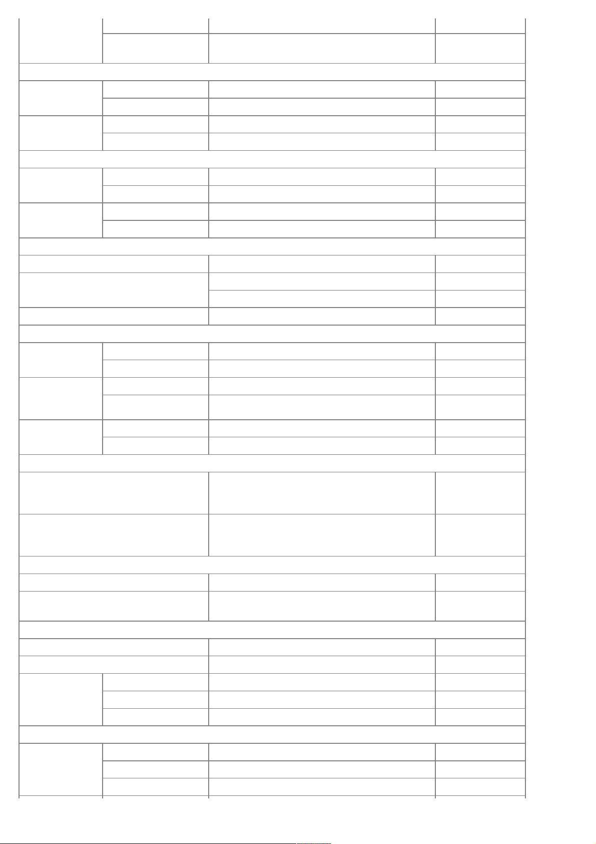
Description Specifications Limit
General
Type V-type, DOHC
Number of cylinders 6
Bore 96mm(3.7795in)
Stroke 87.0mm(3.4252in)
Total displacement 3.778cc(230.55cu.in.)
Compression ratio 10.4
Firing order 1-2-3-4-5-6
Valve timing
Intake Opens(ATDC) 10°
Closes(ABDC) 62°
Exhaust Opens(BBDC) 42°
Closes(ATDC) 6°
Cylinder head
Flatness of gasket surface Less than 0.05mm (0.0019in.)
[Less than 0.02mm (0.0008in.) / 150x150]
Flatness of
manifold mounting
Intake
Less than 0.1mm(0.0039in.)
[Less than 0.03mm(0.001in)/110x110]
Exhaust
Less than 0.1mm(0.0039in.)
[Less than 0.03mm(0.001in)/110x110]
Camshaft
Cam height LH
Camshaft
Intake 46.8mm(1.8425in.)
Exhaust 45.8mm (1.8031in.)
RH
Camshaft
Intake 46.8mm(1.8425in.)
Exhaust 45.8mm (1.8031in.)
Journal outer
diameter
LH
,RHcamshaft
Intake No.1: 27.964 ~ 27.980mm (1.1009 ~ 1.1016in.)
No.2,3,4: 23.954 ~ 23.970mm (0.9430 ~ 0.9437in.)
Exhaust No.1: 27.964 ~ 27.980mm (1.1009 ~ 1.1016in.)
No.2,3,4: 23.954 ~ 23.970mm (0.9430 ~ 0.9437in.)
Bearing oil
clearance
LH
,RHcamshaft
Intake No.1: 0.020 ~ 0.057mm (0.0008 ~ 0.0022in.)
No.2,3,4: 0.030 ~ 0.067mm (0.0012 ~ 0.0026in.)
Exhaust No.1: 0.020 ~ 0.057mm (0.0008 ~ 0.0022in.)
No.2,3,4: 0.030 ~ 0.067mm (0.0012 ~ 0.0026in.)
End play 0.02 ~ 0.18mm (0.0008 ~ 0.0071in.)
Valve
Valve length Intake 105.27mm(4.1445in.)
Exhaust 105.50mm (4.1535in.)
Stem outer
diameter
Intake 5.465 ~ 5.480mm (0.2151 ~ 0.2157in.)
Exhaust 5.458 ~ 5.470mm (0.2149 ~ 0.2153in.)
Face angle 45.25° ~ 45.75°
Thickness of
valvehead(margin)
Intake 1.56 ~ 1.86mm(0.06142 ~ 0.07323in.)
Exhaust 1.73 ~ 2.03mm(0.06811 ~ 0.07992in.)
Valve stem to
Intake
0.07mm
Page 3
valve guide
clearance
0.020 ~ 0.047mm (0.00078 ~ 0.00185in.)
(0.00275in.)
Exhaust
0.030 ~ 0.054mm (0.00118 ~ 0.00212in.)
0.09mm
(0.00354in.)
Valve guide
Inner diameter Intake 5.500 ~ 5.512mm (0.2165 ~ 0.2170in.)
Exhaust 5.500 ~ 5.512mm (0.2165 ~ 0.2170in.)
Length Intake 41.8 ~ 42.2mm (1.6457 ~ 1.6614in.)
Exhaust 41.8 ~ 42.2mm (1.6457 ~ 1.6614in.)
Valve seat
Width of seat
contact
Intake 1.15 ~ 1.45mm(0.05118 ~ 0.05709in.)
Exhaust 1.35 ~ 1.65mm(0.05315 ~ 0.06496in.)
Seat angle Intake 44.75° ~ 45.20°
Exhaust 44.75° ~ 45.20°
Valve spring
Free length 43.86mm (1.7267in.)
Load 19.3±0.8kg/34.0mm (42.7±1.8 lb/1.3386in.)
42.3±1.3kg/24.2mm (93.3±2.9 lb/0.9527in.)
Out of squareness Less than 1.5°
MLA
MLA outer
diameter
Intake 34.964 ~ 34.980mm (1.3765 ~ 1.3772in.)
Exhaust 34.964 ~ 34.980mm (1.3765 ~ 1.3772in.)
Cylinder head
tappet bore inner
diameter
Intake 35.000 ~ 35.025mm (1.3779 ~ 1.3789in.)
Exhaust 35.000 ~ 35.025mm (1.3779 ~ 1.3789in.)
MLA to tappet
bore clearance
Intake 0.020 ~ 0.061mm (0.0008 ~ 0.0024in.) 0.07mm(0.0027in.)
Exhaust 0.020 ~ 0.061mm (0.0008 ~ 0.0024in.) 0.07mm(0.0027in.)
Valve clearance
Intake
0.17 ~ 0.23mm (0.0067 ~ 0.0090in.)
0.10 ~ 0.30mm
(0.0039 ~
0.0118in.)
Exhaust
0.27 ~ 0.33mm (0.0106 ~ 0.0129in.)
0.20 ~ 0.40mm
(0.0078 ~
0.0157in.)
Cylinder block
Cylinder bore 96.00 ~ 96.03mm (3.7795 ~ 3.7807in.)
Flatness of gasket surface
Less than 0.05mm (0.0019in.)
[Less than 0.02mm (0.0008in.) / 150x150]
Piston
Piston outer diameter 95.96 ~ 95.99mm(3.7779 ~ 3.7791in.)
Piston to cylinder clearance 0.03 ~ 0.05mm(0.0012 ~ 0.0020in.)
Ring groove width No. 1 ring groove 1.22 ~ 1.24mm (0.0480 ~ 0.0488in.) 1.26mm (0.0496in.)
No. 2 ring groove 1.22 ~ 1.24mm (0.0480 ~ 0.0488in.) 1.26mm (0.0496in.)
Oil ring groove 2.01 ~ 2.03mm (0.0791 ~ 0.0799in.) 2.05mm (0.0807in.)
Piston ring
Side clearance No. 1 ring 0.03 ~ 0.07mm (0.0012 ~ 0.0027in.) 0.1mm (0.004in.)
No. 2 ring 0.03 ~ 0.07mm (0.0012 ~ 0.0027in.) 0.1mm (0.004in.)
Oil ring 0.06 ~ 0.15mm (0.0024 ~ 0.0059in.) 0.2mm (0.008in.)
Page 4
End gap No. 1 ring 0.17 ~ 0.32mm (0.0067 ~ 0.0126in.) 0.6mm (0.0236in.)
No. 2 ring 0.32 ~ 0.47mm (0.0126 ~ 0.0185in.) 0.7mm (0.0275in.)
Oil ring 0.20 ~ 0.70mm (0.0078 ~ 0.0275in.) 0.8mm (0.0315in.)
Piston pin
Piston pin outer diameter 23.001 ~ 23.006mm (0.9055 ~ 0.9057in.)
Piston pin hole inner diameter 23.016 ~ 23.021mm (0.9061 ~ 0.9063in.)
Piston pin hole clearance 0.01 ~ 0.02mm (0.0039 ~ 0.0078in.)
Connecting rod small end inner diameter 22.974 ~ 22.985mm (0.9045 ~ 0.9049in.)
Connecting rod small end hole clearance -0.032 ~ -0.016mm (-0.0012 ~ 0.0006in.)
Connecting rod
Connecting rod big end innerdiameter 58.000 ~ 58.018mm(2.2834 ~2.2842in.)
Connecting rod bearing oil clearance 0.038 ~ 0.056mm (0.0015 ~ 0.0022in.)
Side clearance 0.1 ~ 0.25mm (0.0039 ~ 0.0098in.)
Crankshaft
Main journal outer diameter 68.942 ~ 68.960mm (2.7142 ~ 2.7149in.)
Pin journal outer diameter 54.954 ~ 54.972mm (2.1635 ~ 2.1642in.)
Main bearing oil clearance 0.022 ~ 0.040mm (0.0008 ~ 0.0016in.)
End play 0.10 ~ 0.28mm (0.0039 ~ 0.0110in.)
Oil pump
Relief valve opening pressure
450 ~ 550kPa
(4.59 ~ 5.61kgf/cm!,65.28 ~ 79.79psi)
Engine oil
Oil quantity (Total) 6.0 L (6.34 US qt, 5.27 lmp qt)
Oil quantity (Oil pan) 5.5 L (5.81 US qt, 4.83 lmp qt)
Oil quantity (Drain and refill including oil
filter)
5.2 L (5.49 US qt, 4.57 lmp qt)
Oil quality ABOVE API SJ / SL or SAE 5W-20
Oil pressure
130kPa(1.32kgf/cm!,18.77psi)
[at 1000rpm,110°C(230°F)]
Cooling system
Cooling method Forced circulation with electrical fan
Coolant quantity 8.6L(9.09U.S.qts,7.57lmp.qts)
Thermostat Type Wax pellet type
Opening temperature 82±2°C (179.6±35.6°F)
Fully
openedtemperature
95°C (203°F)
Full lift 10mm (0.3937in.)
Radiator cap Main valve opening
pressure
93.16 ~ 122.58kpa
(0.95 ~ 1.25kg/cm!, 13.51 ~ 17.78psi)
Vacuum valve opening
pressure
0.98 ~ 4.90 kpa
(0.01 ~ 0.05kg/cm!, 0.14 ~ 0.71 psi)
Water temperature sensor
Type Thermister type
Resistance 20°C (68°F) 2.31 ~ 2.59K"
80°C(176°F) 0.3222 K"
Page 5

TIGHTENING TORQUE
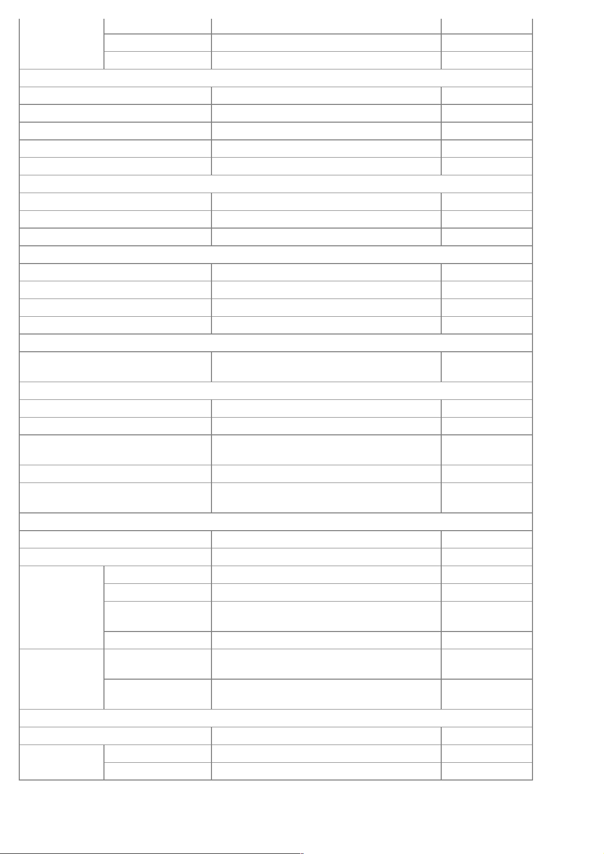
Item Quantity Nm kgf.m lb-ft
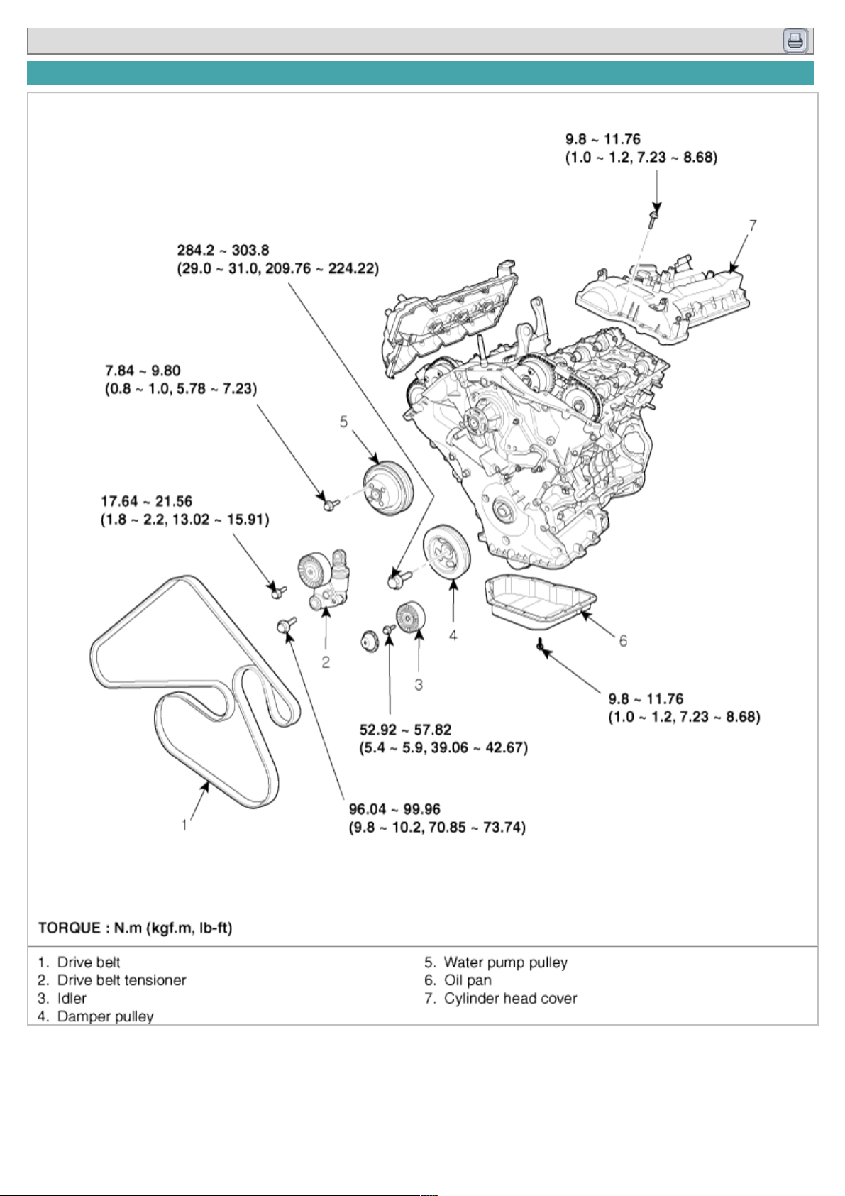
Crankshaft pulley bolt 1 284.2 ~ 303.8 29.0 ~ 31.0 209.76 ~ 224.22
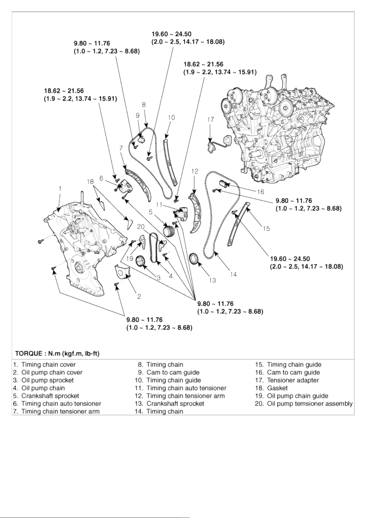
Timing chain cover bolt B 17 18.62 ~ 21.56 1.9 ~ 2.2 13.74 ~ 15.91
Timing chain cover bolt C 4 9.80 ~ 11.76 1.0 ~ 1.2 7.23 ~ 8.68
Timing chain cover bolt D 1 58.80 ~ 68.80 6.0 ~ 7.0 43.40 ~ 50.63
Timing chain cover bolt E 1 58.80 ~ 68.80 6.0 ~ 7.0 43.40 ~ 50.63
Timing chain cover bolt F 2 24.50 ~ 26.46 2.5 ~ 2.7 18.08 ~ 19.53
Timing chain cover bolt G 4 21.56 ~ 23.52 2.2 ~ 2.4 15.91 ~ 17.36
Timing chain cover bolt H 1 9.80 ~ 11.76 1.0 ~ 1.2 7.23 ~ 8.68
Timing chain cover bolt I 1 9.80 ~ 11.76 1.0 ~ 1.2 7.23 ~ 8.68
Timing chain cover bolt J 1 9.80 ~ 11.76 1.0 ~ 1.2 7.23 ~ 8.68
Cam to cam guide bolt 4 9.80 ~ 11.76 1.0 ~ 1.2 7.23 ~ 8.68
Timing chain auto tensioner bolt 2 9.80 ~ 11.76 1.0 ~ 1.2 7.23 ~ 8.68
Timing chain auto tensioner nut 2 9.80 ~ 11.76 1.0 ~ 1.2 7.23 ~ 8.68
Timing chain guide bolt 4 19.60 ~ 24.50 2.0 ~ 2.5 14.17 ~ 18.08
Oil pump chain cover bolt 3 9.80 ~ 11.76 1.0 ~ 1.2 7.23 ~ 8.68
Oil pump chain tensioner bolt 1 9.80 ~ 11.76 1.0 ~ 1.2 7.23 ~ 8.68
Oil pump chain guide bolt 2 9.80 ~ 11.76 1.0 ~ 1.2 7.23 ~ 8.68
Oil pump chain sprocket bolt 1 18.62 ~ 21.56 1.9 ~ 2.2 13.74 ~ 15.91
Lower oil pan bolt 13 9.80 ~ 11.76 1.0 ~ 1.2 7.23 ~ 8.68
Drive belt auto tensioner bolt(M12) 1 96.04 ~ 99.96 9.8 ~ 10.2 70.88 ~ 73.78
Drive belt auto tensioner bolt(M8) 1 17.64 ~ 21.56 1.8 ~ 2.2 13.02 ~ 15.91
Drive belt idler bolt 1 53.90 ~ 57.82 5.5 ~ 5.9 39.78 ~ 42.67
OCV(oil control valve) bolt 2 9.80 ~ 11.76 1.0 ~ 1.2 7.23 ~ 8.68
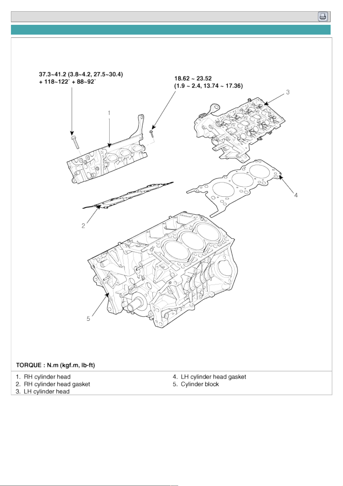
Cylinder head bolt 16
(37.3~41.2) +
(118~122°) +
(88~92°)
(3.8~4.2) +
(118~122°) +
(88~92°)
(27.5~30.4) +
(118~122°) +
(88~92°)
Cylinder head bolt 1 18.62 ~ 23.52 1.9 ~ 2.4 13.74 ~ 17.36
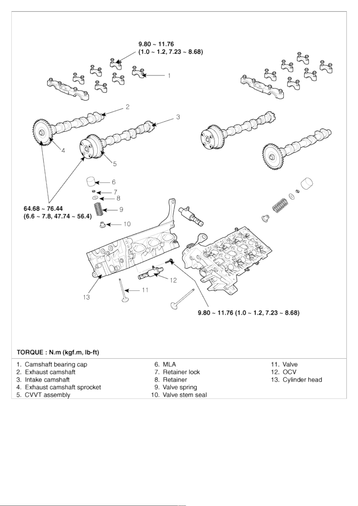
CVVT & exhaust cam sprocket bolt 4 64.68 ~ 76.44 6.6 ~ 7.8 47.74 ~ 56.42
Camshaft bearing cap bolt 32 9.80 ~ 11.76 1.0 ~ 1.2 7.23 ~ 8.68
Cylinder head cover bolt 38 9.80 ~ 11.76 1.0 ~ 1.2 7.23 ~ 8.68
Connecting rod bearing bolt 12
(17.7~21.6) +
(88~92°)
(1.8~2.2) +
(88~92°)
(13.0~15.9) +
(88~92°)
Main bearing cap inner bolt(M11) 8 49.00 + 90° 5.0 + 90° 36.16 + 90°
Main bearing cap outer bolt(M8) 8 19.60 + 120° 2.0 + 120° 14.46 + 120°
Main bearing cap side bolt(M8) 6 29.40 ~ 31.36 3.0 ~ 3.2 21.70 ~ 23.14
Oil drain cover bolt 6 9.80 ~ 11.76 1.0 ~ 1.2 7.23 ~ 8.68
Rear oil seal case bolt 6 9.80 ~ 11.76 1.0 ~ 1.2 7.23 ~ 8.68
Baffle plate bolt 12 9.80 ~ 11.76 1.0 ~ 1.2 7.23 ~ 8.68
Upper oil pan bolt 16 9.80 ~ 11.76 1.0 ~ 1.2 7.23 ~ 8.68
Knock sensor bolt 2 15.68 ~ 23.52 1.6 ~ 2.4 11.57 ~ 17.36
Drive plate bolt cap 8 71.54 ~ 75.46 7.3 ~ 7.7 52.80 ~ 55.69
Oil filter cap 24.50 2.5 18.08
Oil drain bolt cap 1 34.30 ~ 44.10 3.5 ~ 4.5 25.31 ~ 32.55
Page 6
Oil pump bolt 3 19.6 ~ 23.5 2.0 ~ 2.4 14.5 ~ 17.4
Oil filter body bolt 10 9.80 ~ 11.76 1.0 ~ 1.2 7.23 ~ 8.68
Oil filter body cover bolt 11 9.80 ~ 11.76 1.0 ~ 1.2 7.23 ~ 8.68
Water vent hose bolt(Timing chain cover bolt L) 2 9.80 ~ 11.76 1.0 ~ 1.2 7.23 ~ 8.68
Water pump bolt(Timing chain cover bolt K) 1 21.56 ~ 26.46 2.2 ~ 2.7 15.91 ~ 19.53
Water pump bolt 4 9.80 ~ 11.76 1.0 ~ 1.2 7.23 ~ 8.68
Water pump pulley bolt 4 7.84 ~ 9.80 0.8 ~ 1.0 5.78 ~ 7.23
Water temp. control nut 4 18.62 ~ 23.52 1.9 ~ 2.4 13.74 ~ 17.36
Water temp. control bolt 2 18.62 ~ 23.52 1.9 ~2.4 13.74 ~ 17.36
Water inlet pipe bolt 3 16.66 ~ 19.60 1.7 ~ 2.0 12.30 ~ 14.47
Air vent pipe bolt 2 9.80 ~ 11.76 1.0 ~ 1.2 7.23 ~ 8.68
Intake manifold bolt 6 18.62 ~ 23.52 1.9 ~ 2.4 13.74 ~ 17.36
Intake manifold nut 2 18.62 ~ 23.52 1.9 ~ 2.4 13.74 ~ 17.36
Surge tank bolt (M8 # 25) 3 18.62 ~ 23.52 1.9 ~ 2.4 13.74 ~ 17.36
Surge tank bolt (M6 # 106) 2 9.80 ~ 11.76 1.0 ~ 1.2 7.23 ~ 8.68
Surge tank nut 1 18.62 ~ 23.52 1.9 ~ 2.4 13.74 ~ 17.36
Breather pipe bolt 2 9.80 ~ 11.76 1.0 ~ 1.2 7.23 ~ 8.68
Surge tank bracket bolt rear (M10 # 18 ) 2 27.44 ~ 31.36 2.8 ~ 3.2 20.25 ~ 23.14
Surge tank bracket bolt front (M8 # 16) 2 18.62 ~ 23.52 1.9 ~ 2.4 13.74 ~ 17.36
ETC bracket bolt 2 15.68 ~ 25.48 1.6 ~ 2.6 11.57 ~ 18.80
Exhaust manifold nut 16 39.20 ~ 44.10 4.0 ~ 4.5 28.93 ~ 32.55
Heat proctor bolt 8 3.9 ~ 5.9 0.4 ~ 0.6 2.89 ~ 4.34
Front muffler 2 39.20 ~ 58.80 4.0 ~ 6.0 28.93 ~ 43.40
COMPRESSION
If the there is lack of power, excessive oil consumption or poor fuel economy, measure the compression
pressure.
1. Warm up and stop engine.
Allow the engine to warm up to normal operating temperature.
2. Remove the surge tank.
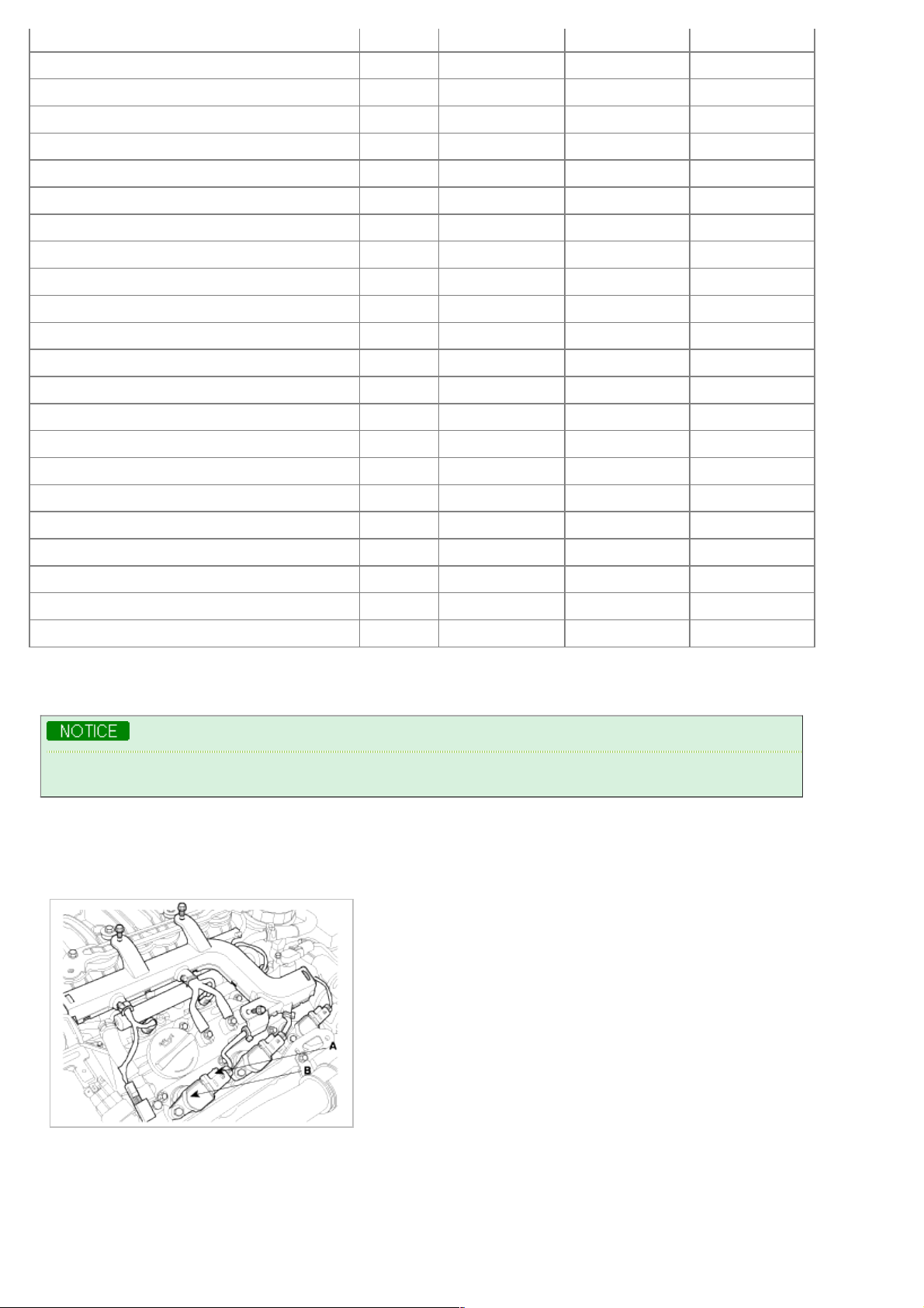
3. Remove the ignition coil connectors(A) and ignition coils(B).
4. Remove the spark plugs.
Using a 16mm plug wrench, remove the 6 spark plugs.
5. Check cylinder compression pressure.
(1) Insert a compression gauge into the spark plug hole.
(2) Fully open the throttle.
Page 7
(2) Fully open the throttle.
(3) After 7 times of cranking the engine, measure the compression pressure.
Always use a fully charged battery to obtain engine speed of 250 rpm or more.
Repeat steps 1) through 3) for each cylinder.
This measurement must be done in as short a time as possible.
Compression pressure :
1,225kPa (12.5kgf/cm!, 177psi) - 200 ~ 250rpm
Minimum pressure :
1,078kPa (11.0kgf/cm!, 156psi)
(4) If the cylinder compression in 1 or more cylinders is low, pour a small amount of engine oil into the cylinder
through the spark plug hole and repeat steps (a) through (c) for cylinders with low compression.
A. If adding oil helps the compression, it is likely that the piston rings and/or cylinder bore are worn or
damaged.
B. If pressure stays low, a valve may be sticking or seating is improper, or there may be leakage past the
gasket.
6. Reinstall the spark plugs.
7. Install the ignition coil and ignition coil connectors.
8. Install the surge tank.
VALVE CLEARANCE INSPECTION AND ADJUSTMENT
Inspect and adjust the valve clearance when the engine is cold (Engine coolant temperature : 20°C) and cylinder
head is installed on the cylinder block.
1. Remove the engine cover.
2. Remove air cleaner assembly.
3. Remove the surge tank.
4. Remove the cylinder head cover.
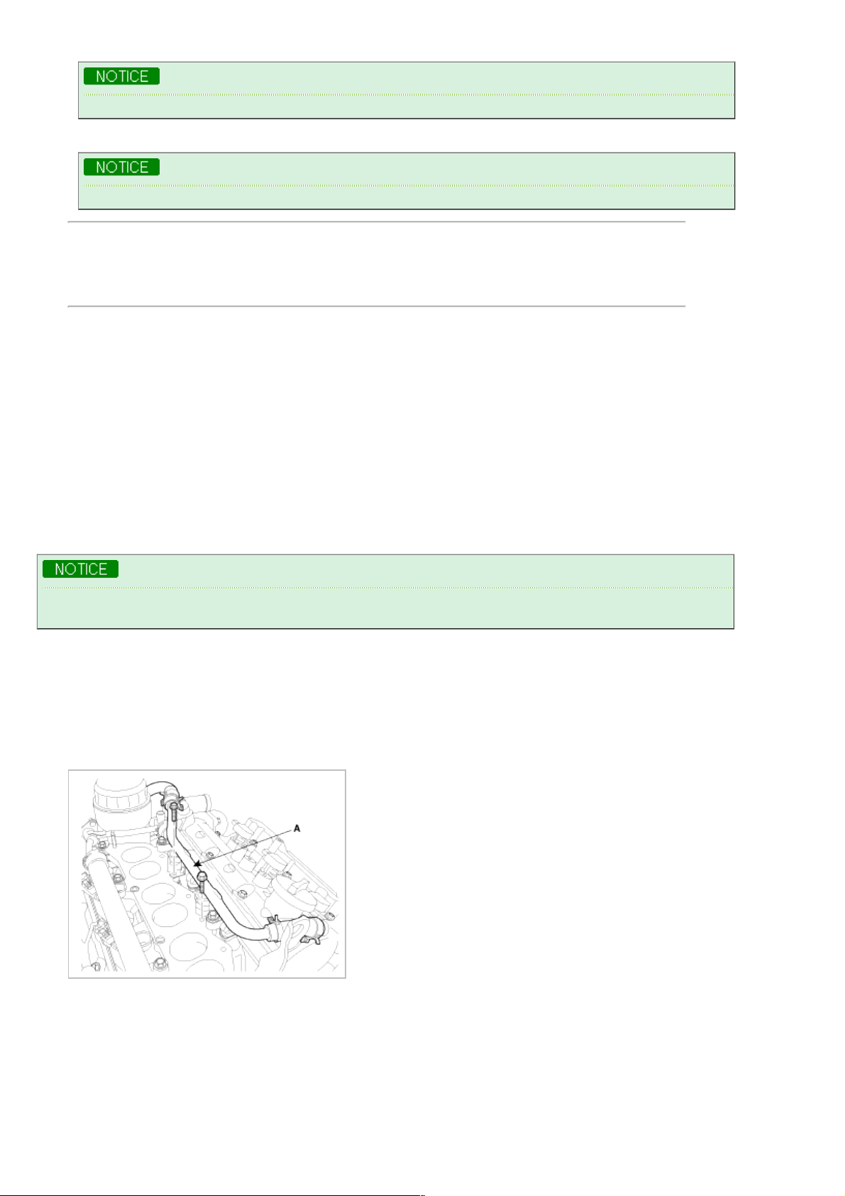
(1) Disconnect the ignition coil connector and remove the ignition coil.
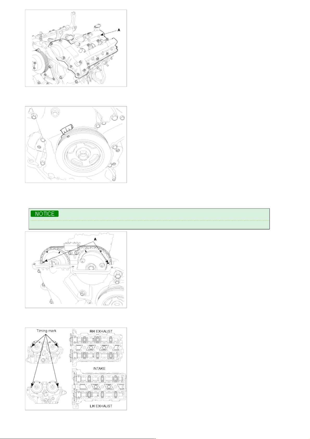
(2) Disconnect the breather pipe assembly(A) from the cylinder head cover.
(3) Loosen the cylinder head cover bolts and then remove the cover(A) and gasket.
Page 8
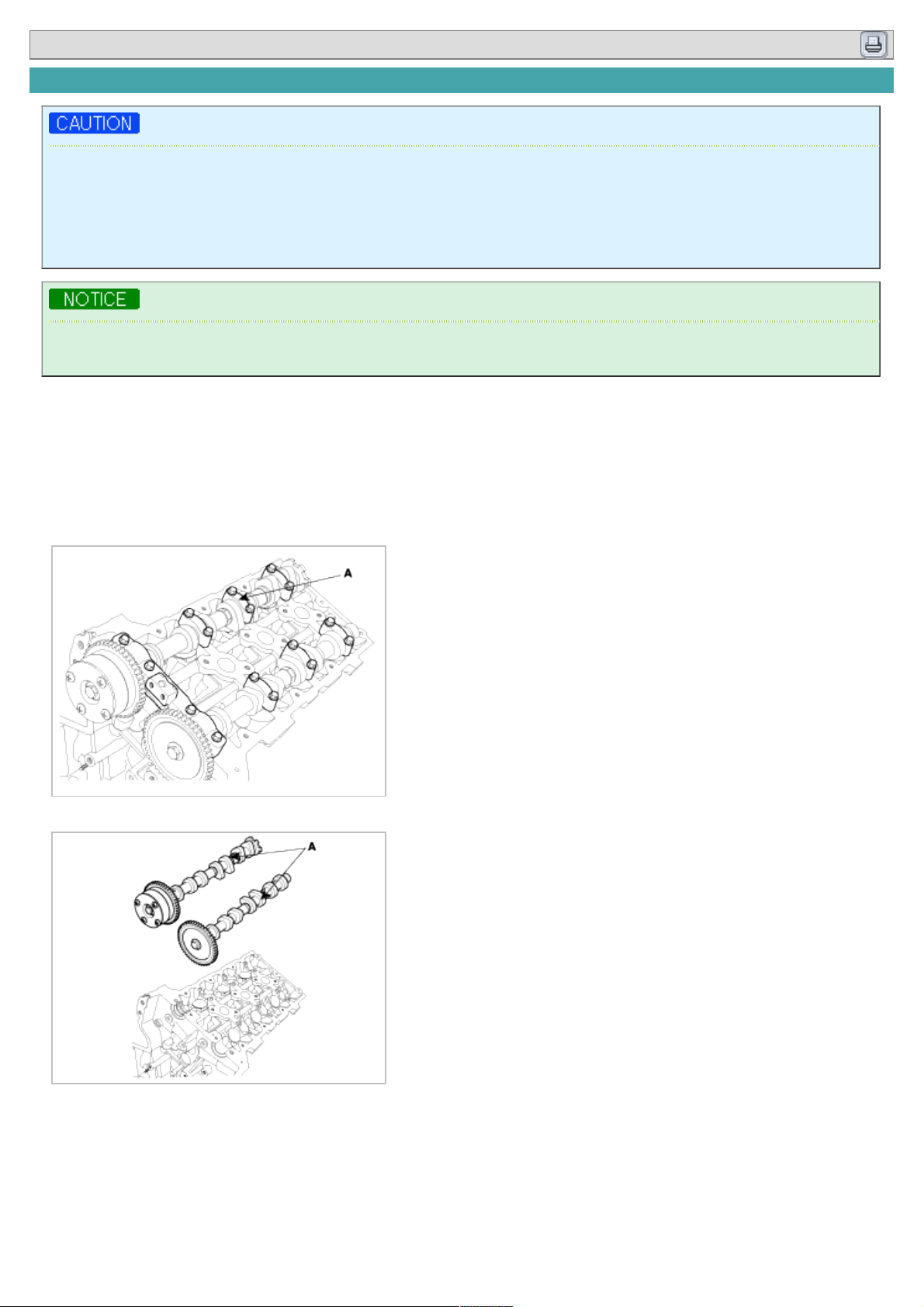
5. Set No.1 cylinder to TDC/compression.
(1) Turn the crankshaft pulley and align its groove with the timing mark "T" of the lower timing chain cover.
(2) Check that the mark(A) of the camshaft timing sprockets are in straight line on the cylinder head surface as
shown in the illustration.
If not, turn the crankshaft one revolution (360°)
Do not rotate engine counterclockwise
6. Inspect the valve clearance.
(1) Check only the valve indicated as shown. [No. 1 cylinder : TDC/Compression] measure the valve clearance.
Measurement method.
Page 9
A. $ Using a thickness gauge, measure the clearance between the tappet and the base circle of camshaft.
$ Record the out-of-specification valve clearance measurements. They will be used later to determine the
required replacement adjusting tappet.
Valve clearance
Specification
Engine coolant temperature : 20°C [68°F]
Limit
Intake : 0.10 ~ 0.30mm (0.0039 ~ 0.0118in.)
Exhaust : 0.20 ~ 0.40mm (0.0079 ~ 0.0157in.)
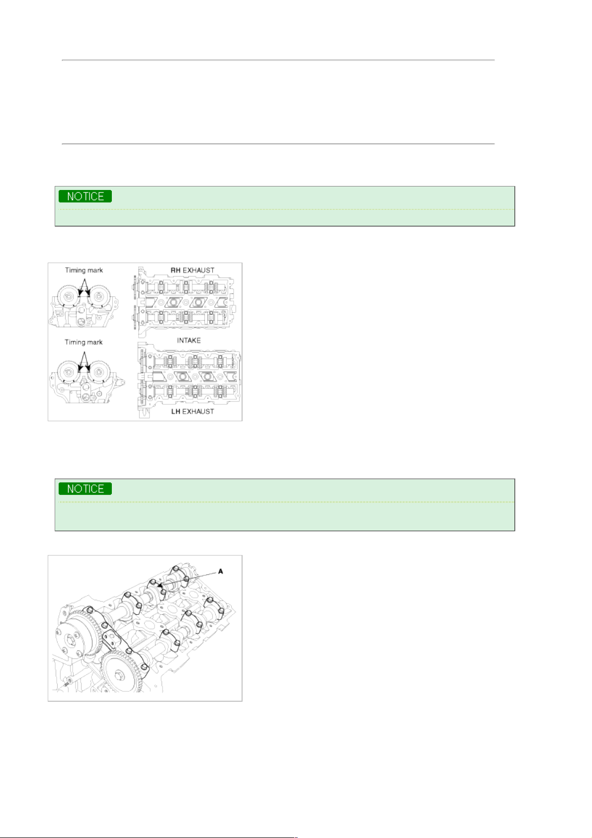
(2) Turn the crankshaft pulley one revolution (360°) and align the groove with timing mark "T" of the lower timing
chain cover.
Do not rotate engine counterclockwise
(3) Check only valves indicated as shown. [NO. 4 cylinder : TDC/compression]. Measure the valve clearance.
(Refer to procedure step1))
7. Adjust the intake and exhaust valve clearance.
(1) Set the No.1 cylinder to the TDC/compression.
(2) Remove the timing chain.
Before removing the timing chain, mark the RH/LH timing chain with an identification based on the location
of the sproket because the identification mark on the chain for TDC(Top Dead Center) can be erased.
(3) Remove the camshaft bearing caps(A).
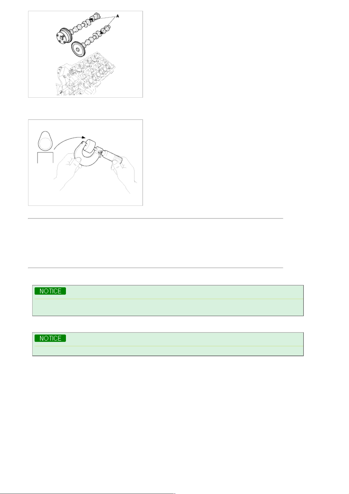
(4) Remove the camshaft assembly(A).
Page 10
(5) Remove MLAs.
(6) Measure the thickness of the removed tappet using a micrometer.
(7) Calculate the thickness of a new tappet so that the valve clearance comes within the specified value.
Valve clearance(Engine coolant temperature: 20°C[68°F])
T : Thickness of removed tappet
A : Measured valve clearance
N : Thickness of new tappet
Intake : N = T + [A - 0.20mm(0.0079in.)]
Exhaust : N = T + [A - 0.30mm (0.0118in.)]
(8) Select a new tappet with a thickness as close as possible to the calculated value.
Shims are available in 41size increments of 0.015mm (0.0006in.) from 3.00mm (0.118in.) to 3.600mm
(0.1417in.)
(9) Place a new tappet on the cylinder head.
Appling engine oil at the selected tappet on the periphery and top surface.
(10) Install the intake and exhaust camshaft.
(11) Install the bearing caps
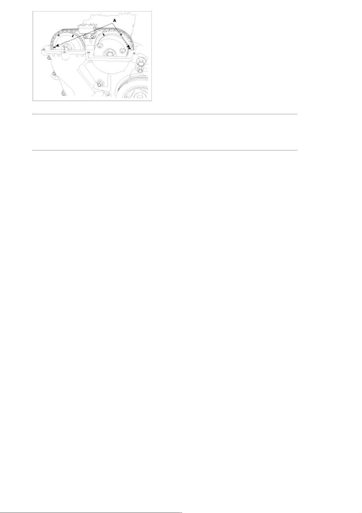
(12) Install the timing chain.
(13) Turn the crankshaft two turns in the operating direction(clockwise) and realign crankshaft sprocket and
camshaft sprocket timing marks(A).
Page 11
(14) Recheck the valve clearance.
Valve clearance (Engine coolant temperature: 20°C[68°F])
[Specification]
Intake : 0.17 ~ 0.23mm (0.0067 ~ 0.0090in.)
Exhaust : 0.27 ~ 0.33mm (0.0106 ~ 0.0129in.)
Page 12
2009 > G 3.8 DOHC >
SPECIAL SERVICE TOOLS
Tool (Number and name) Illustration Use
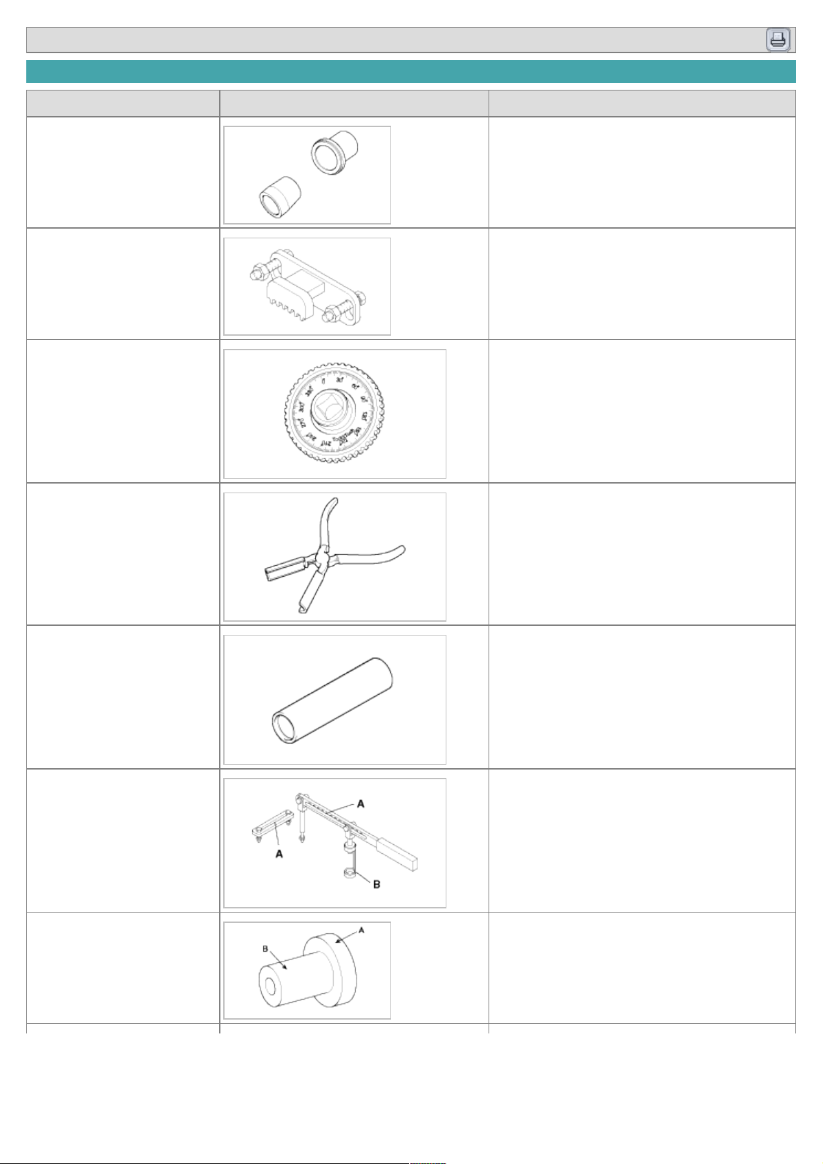
Crankshaft front oil seal
installer
(09231-3C100)
Installation of the front oil seal
Flywheel stopper
(09231-3C300)
Removal and installation of the flywheel and
crankshaft pulley.
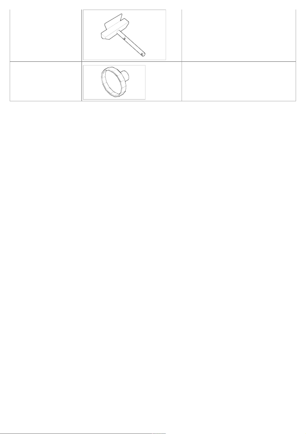
Torque angle adapter
(09221-4A000)
Installation of bolts & nuts needing an angular
method
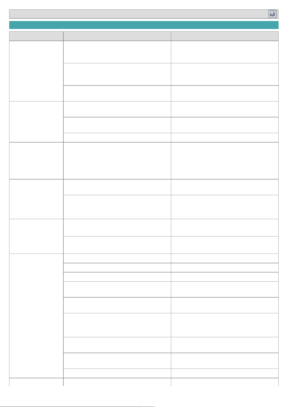
Valve stem seal remover
(09222-29000)
Remover of the valve stem seal
Valve stem seal remover
(09222-3C100)
Installation of the valve stem seal
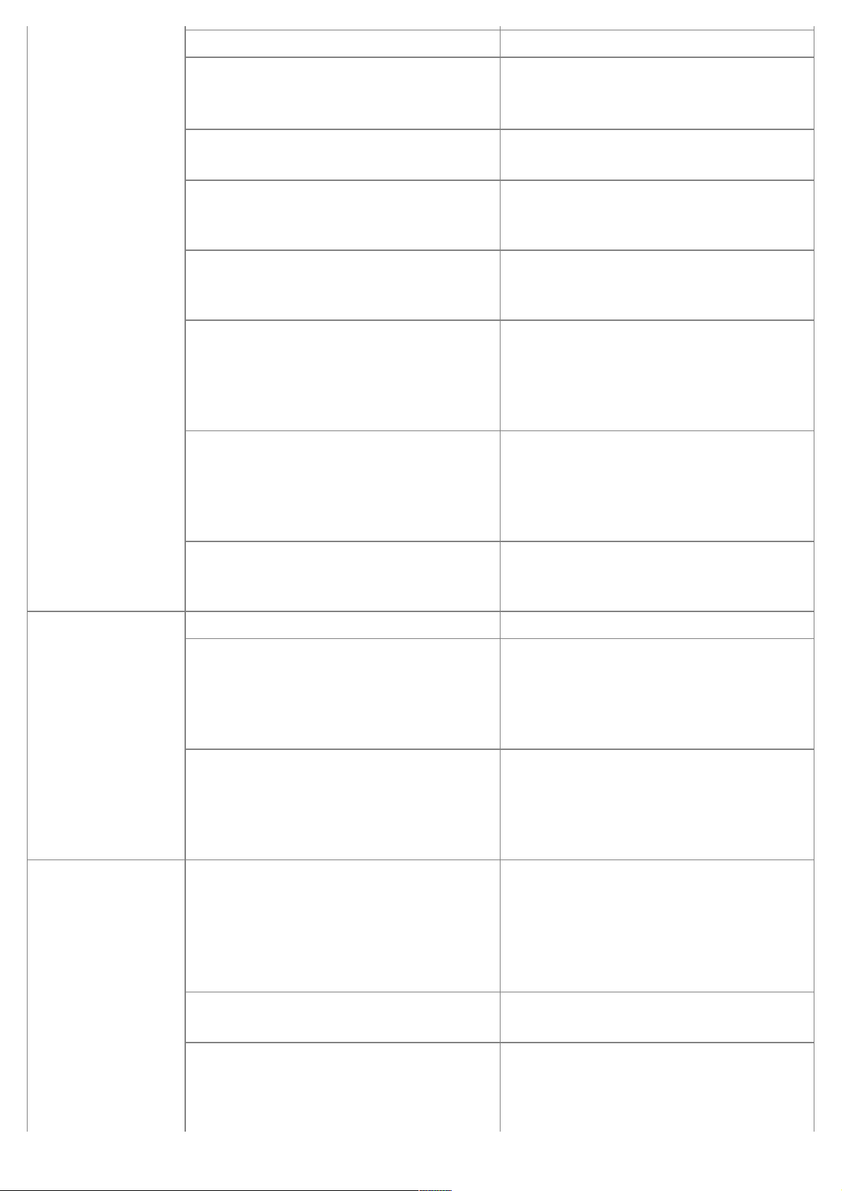
Valve spring compressor &
holder
(09222-3K000)
(09222-3C300)
Removal and installation of the intake or
exhaust valve
A : 09222-3K000
B : 09222-3C300 (holder)
Crankshaft rear oil seal
installer
(09231-3C200)
(09231-H1100)
Installation of the crankshaft rear oil seal
A : 09231-3C200
B : 09231-H1100
Page 13
Oil pan remover
(09215-3C000)
Removal of oil pan
Oil filter wrench
(09263-3C100)
Removal and installation of the oil filter
housing cover
Page 14
2009 > G 3.8 DOHC >
TROUBLESHOOTING
Symptom Suspect area Remedy
Engine misfire with
abnormal internal
lower engine noises.
Worn crankshaft bearings.
Loose or improperly installed engine drive
plate.
Replace the crankshaft and bearings as
required.
Repair or replace the drive plate as required.
Worn piston rings.
(Oil consumption may or may not cause the
engine to misfire.)
Inspect the cylinder for a loss of compression.
Repair or replace as required.
Worn crankshaft thrust bearings
Replace the crankshaft and bearings as
required.
Engine misfire with
abnormal valve train
noise.
Stuck valves.
(Carbon buildup on the valve stem)
Repair or replace as required.
Excessive worn or mis-aligned timing chain. Replace the timing chain and sprocket as
required.
Worn camshaft lobes. Replace the camshaft and valve lifters.
Engine misfire with
coolant consumption.
• Malfunctioning cylinder head gasket and/or
cranking or other damage to the cylinder
head and engine block cooling system.
• Coolant consumption may or may not
cause the engine to overheat.
• Inspect the cylinder head and engine
block for damage to the coolant passages
and/or a malfunctioning head gasket.
• Repair or replace as required.
Engine misfire with
excessive oil
consumption.
Worn valves, guides and/or valve stem oil
seals.
Repair or replace as required.
Worn piston rings.
(Oil consumption may or may not cause the
engine to misfire)
• Inspect the cylinder for a loss of
compression.
• Repair or replace as required.
Engine noise on startup, but only lasting a
few seconds.
Incorrect oil viscosity.
• Drain the oil.
• Install the correct viscosity oil.
Worn crankshaft thrust bearing.
• Inspect the thrust bearing and crankshaft.
• Repair or replace as required.
Upper engine
noise,regardless of
engine speed.
Low oil pressure. Repair or replace as required.
Broken valve spring. Replace the valve spring.
Worn or dirty valve lifters. Replace the valve lifters.
Stretched or broken timing chain and/or
damaged sprocket teeth.
Replace the timing chain and sprockets.
Worn timing chain tensioner, if applicable. Replace the timing chain tensioner as
required.
Worn camshaft lobes.
• Inspect the camshaft lobes.
• Replace the timing camshaft and valve
lifters as required.
Worn valve guides or valve stems. Inspect the valves and valve guides,then
repair as required.
Stuck valves. (Carbon on the valve stem or
valve seat may cause the valve to stay open.
Inspect the valves and valve guides, then
repair as required.
Worn drive belt, idler, tensioner and bearing. Replace as required.
Lower engine
Low oil pressure. Repair or required.
Page 15
noise,regardless of
engine speed.
Loose or damaged drive plate. Repair or replace the drive plate.
Damaged oil pan, contacting the oil pump
screen.
• Inspect the oil pan.
• Inspect the oil pump screen.
• Repair or replace as required.
Oil pump screen loose, damaged or
restricted.
• Inspect the oil pump screen.
• Repair or replace as required.
Excessive piston-to-cylinder bore clearance.
• Inspect the piston, piston pin and cylinder
bore.
• Repair as required.
Excessive piston pin-to-piston clearance.
• Inspect the piston, piston pin and the
connecting rod.
• Repair or replace as required.
Excessive connecting rod bearing clearance Inspect the following components and repair
as required.
• The connecting rod bearings.
• The connecting rods.
• The crankshaft pin journals.
Excessive crankshaft bearing clearance. Inspect the following components, and repair
as required.
• The crankshaft bearings.
• The crankshaft main journals.
• The cylinder block.
Incorrect piston, piston pin and connecting rod
installation
• Verify the piston pins and connecting rods
are installed correctly.
• Repair as required.
Engine noise under
load.
Low oil pressure Repair or replace as required.
Excessive connecting rod bearing clearance . Inspect the following components andrepair
as required :
• The connecting rod bearings.
• The connecting rods.
• The crankshaft.
Excessive crankshaft bearing clearance. Inspect the following components, andrepair
as required.
• The crankshaft bearings.
• The crankshaft main journals.
• The cylinder block.
Engine will not crankcrankshaft will not
rotate.
Hydraulically locked cylinder.
• Coolant/antifreeze in cylinder.
• Oil in cylinder.
• Fuel in cylinder.
1. Remove spark plugs and check for fluid.
2. Inspect for broken head gasket.
3. Inspect for cracked engine block or
cylinder head.
4. Inspect for a sticking fuel injector and/or
leaking fuel regulator.
Broken timing chain and/or timing chain
and/or timing chain gears.
1. Inspect timing chain and gears.
2. Repair as required.
Material in cylinder.
• Broken valve
• Piston material
• Foreign material
1. Inspect cylinder for damaged components
and/or foreign materials.
2. Repair or replace as required.
Page 16

Seized crankshaft or connecting rod bearings.
1. Inspect crankshaft and connecting rod
bearing.
2. Repair as required.
Bent or broken connecting rod.
1. Inspect connecting rods.
2. Repair as required.
Broken crankshaft.
1. Inspect crankshaft.
2. Repair as required.
Page 17

Engine Mechanical System
Timing System
Engine Mechanical System
Page 18
2009 > G 3.8 DOHC >
COMPONENT
Page 19
Page 20

Engine Mechanical System
Cylinder Head Assembly
Engine Mechanical System
Page 21
2009 > G 3.8 DOHC >
COMPONENTS
Page 22
Page 23
2009 > G 3.8 DOHC >
REMOVAL
• Use fender covers to avoid damaging painted surfaces.
• To avoid damaging the cylinder head, wait until the engine coolant temperature drops below normal operating
temperature before removing it.
• When handling a metal gasket, take care not to fold the gasket or damage the contact surface of the gasket.
• To avoid damage, unplug the wiring connectors carefully while holding the connector portion.
• Mark all wiring and hoses to avoid misconnection.
• Turn the crankshaft pulley so that the No. 1 piston is at top dead center.
Engine removal is required for this procedure.
1. Remove exhaust manifold.
2. Remove intake manifold.
3. Remove timing chain.
4. Remove water temperature control assembly.
5. Remove camshaft bearing cap(A).
6. Remove camshaft assembly(A).
7. Remove cylinder head bolts, then remove cylinder head.
(1) Uniformly loosen and remove the 16 cylinder head bolts, in several passes, in the sequence shown. Remove
the 16 cylinder head bolts and plate washers.
Page 24
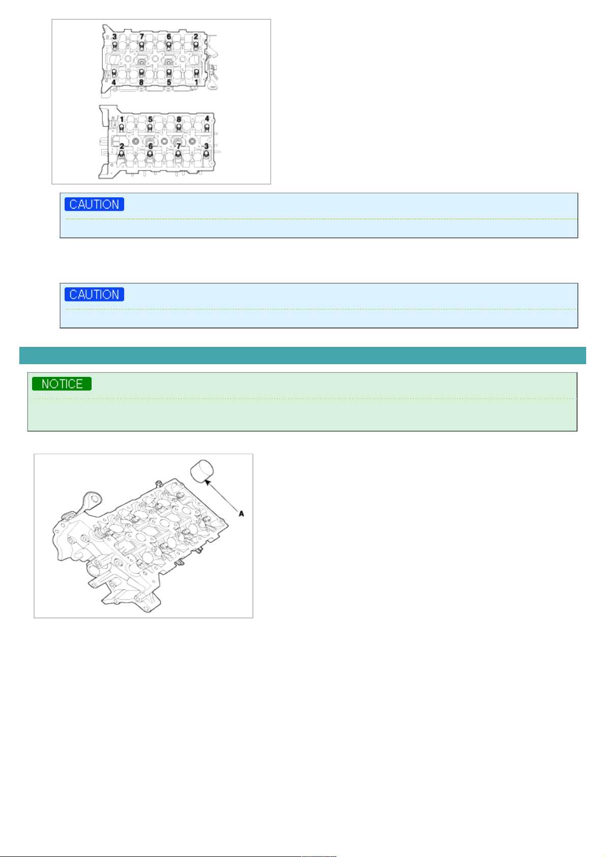
Head warpage or cracking could result from removing bolts in an incorrect order.
(2) Lift the cylinder head from the dowels on the cylinder block and place the cylinder head on wooden blocks on a
bench.
Be careful not to damage the contact surfaces of the cylinder head and cylinder block.
DISASSEMBLY
Identify MLA, valves and valve springs as they are removed so that each item can be reinstalled in its original
position.
1. Remove MLAs(A).
2. Remove valves.
(1) Using SST(09222-3K000, 09222-3C300), compress the valve spring and remove retainer lock.
Page 25

(2) Remove the spring retainer.
(3) Remove the valve spring.
(4) Remove the valve.
(5) Using SST(09222-29000), remove the valve stem seal.
Do not reuse old valve stem seals.
3. Remove OCV(A).
INSPECTION
CYLINDER HEAD
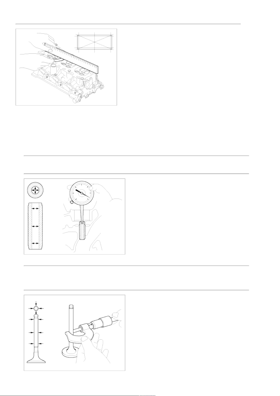
1. Inspect for flatness.
Using a precision straight edge and feeler gauge, measure the surface the contacting the cylinder block and the
manifolds for warpage.
Flatness of cylinder head gasket surface
Standard : Less than 0.05mm(0.002in.)[Less than 0.02mm(0.0008in.)/150x150]
Page 26
Flatness of manifold gasket surface
Standard : Less than 0.03mm(0.001in)/110x110
2. Inspect for cracks.
Check the combustion chamber, intake ports, exhaust ports and cylinder block surface for cracks. If cracked,
replace the cylinder head.
VALVE AND VALVE SPRING
1. Inspect valve stems and valve guides.
(1) Using a caliper gauge, measure the inside diameter of the valve guide.
Valve guide I.D.
Intake / Exhaust : 5.500 ~ 5.512mm (0.216 ~ 0.217in.)
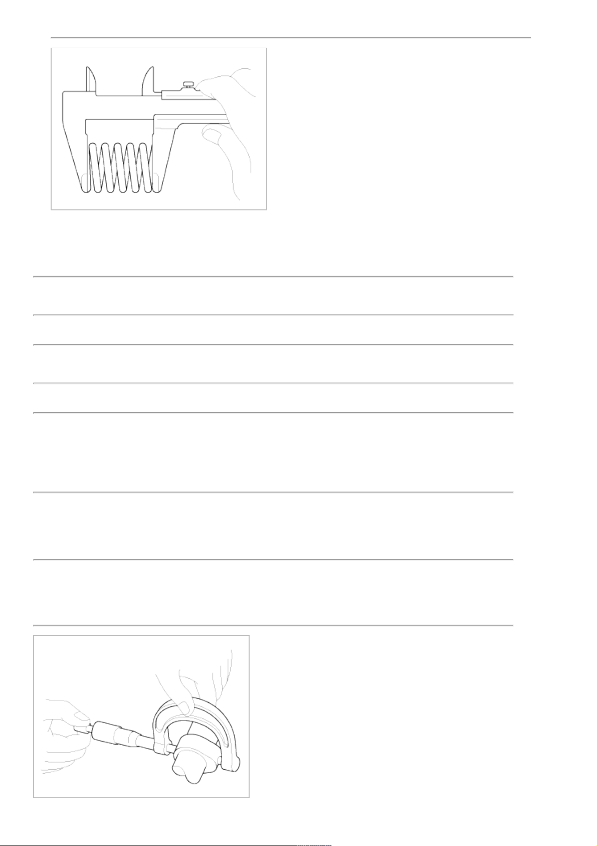
(2) Using a micrometer, measure the diameter of the valve stem.
Valve stem O.D.
Intake : 5.465 ~ 5.480mm (0.2151 ~ 0.2157in.)
Exhaust : 5.458 ~ 5.470mm (0.2149 ~ 0.2153in.)
Page 27
(3) Subtract the valve stem diameter measurement from the valve guide inside diameter measurement.
Valve stem-to-guide clearance
[Standard]
Intake : 0.020 ~ 0.047mm (0.0008 ~ 0.0018in.)
Exhaust : 0.030 ~ 0.054mm (0.0012 ~ 0.0021in.)
[Limit]
Intake : 0.07mm (0.0027in.)
Exhaust : 0.09mm (0.0035in.)
2. Inspect valves.
(1) Check the valve is ground to the correct valve face angle.
(2) Check that the surface of the valve for wear.
If the valve face is worn, replace the valve.
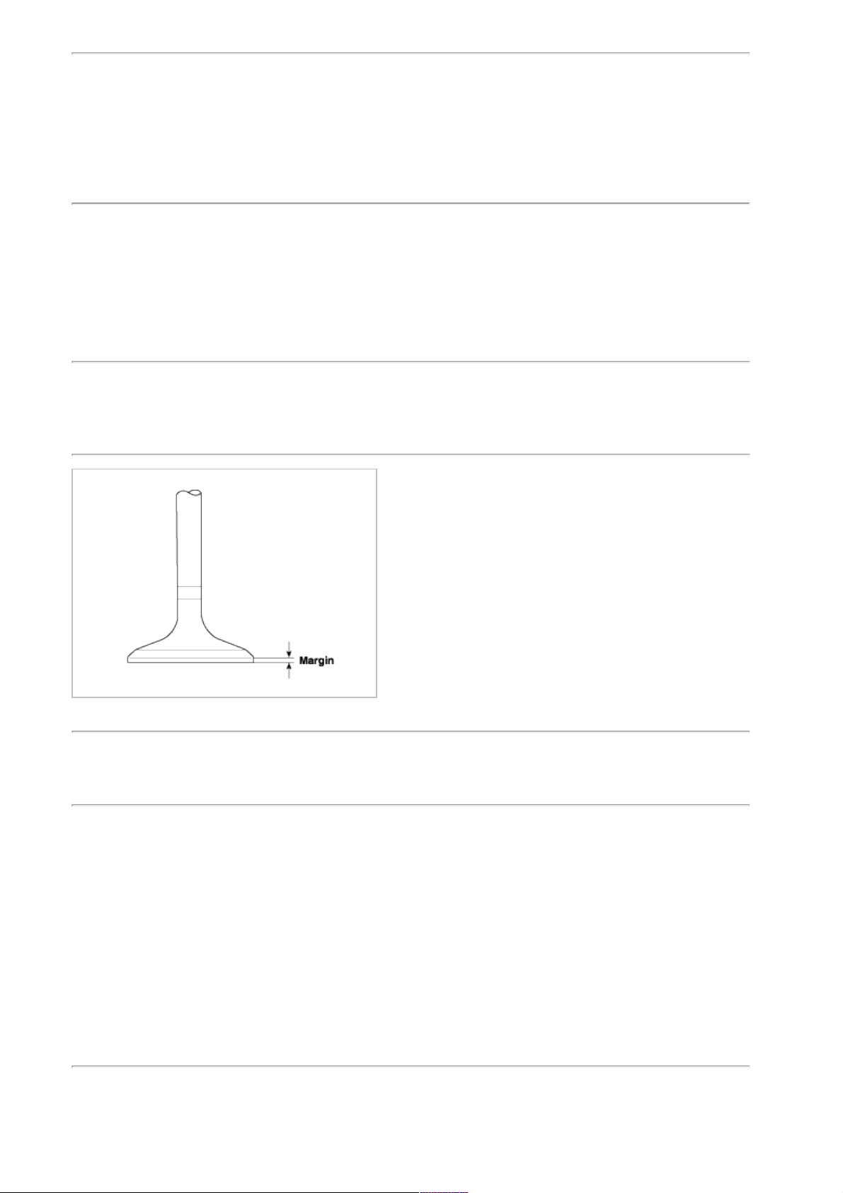
(3) Check the valve head margin thickness.
If the margin thickness is less than minimum, replace the valve.
Margin
[Standard]
Intake : 1.56 ~ 1.86mm(0.06142 ~ 0.07323in.)
Exhaust : 1.73 ~ 2.03mm(0.06811 ~ 0.07992in.)
(4) Check the valve length.
Length
Intake : 105.27mm (4.1445in)
Exhaust : 105.50mm (4.1535in)
(5) Check the surface of the valve stem tip for wear.
If the valve stem tip is worn, replace the valve.
3. Inspect valve seats
Check the valve seat for evidence of overheating and improper contact with the valve face.
If the valve seat is worn, replace cylinder head.
Before reconditioning the seat, check the valve guide for wear. If the valve guide is worn, replace cylinder head.
Recondition the valve seat with a valve seat grinder or cutter. The valve seat contact width should be within
specifications and centered on the valve face.
4. Inspect valve springs.
(1) Using a steel square, measure the out-of-square of the valve spring.
(2) Using a vernier calipers, measure the free length of the valve spring.
Valve spring
[Standard]
Free height : 43.86mm (1.7267in.)
Page 28
Out-of-square : 1.5°
MLA
1. Inspect MLA.
Using a micrometer, measure the MLA outside diameter.
MLA O.D.
Intake/Exhaust : 34.964 ~ 34.980mm(1.3765 ~ 1.3771in.)
2. Using a caliper gauge, measure MLA tappet bore inner diameter of cylinder head.
Tappet bore I.D.
Intake/Exhaust : 35.000 ~ 35.025mm(1.3779 ~ 1.3789in.)
3. Subtract MLA outside diameter measurement from tappet bore inside diameter measurement.
MLA to tappet bore clearance
[Standard]
Intake/Exhaust : 0.020 ~ 0.061mm(0.0008 ~ 0.0024in.)
[Limit]
Intake/Exhaust : 0.07mm(0.0027in.)
CAMSHAFT
1. Inspect cam lobes.
Using a micrometer, measure the cam lobe height.
Cam height
[Standard value]
Intake : 46.8mm (1.8425in.)
Exhaust : 45.8mm (1.8031in.)
Page 29
If the cam lobe height is less than standard, replace the camshaft.
2. Inspect camshaft journal clearance.
(1) Clean the bearing caps and camshaft journals.
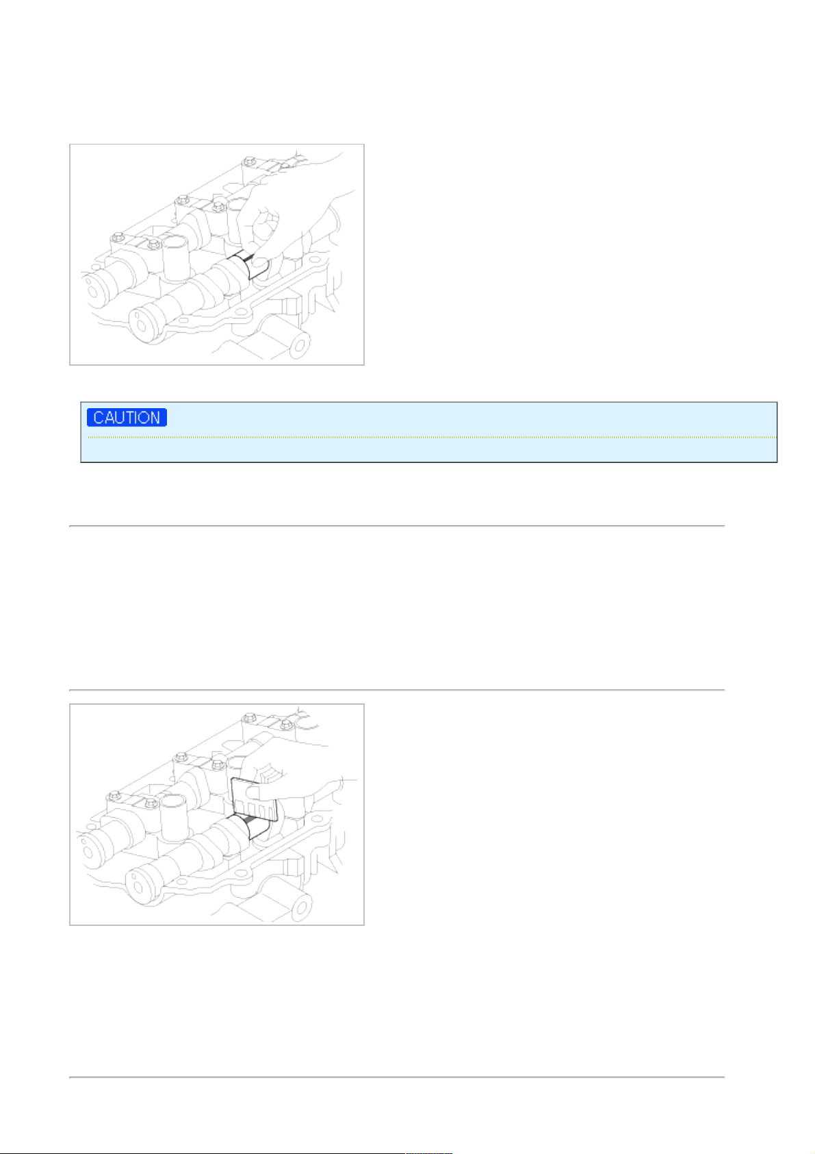
(2) Place the camshafts on the cylinder head.
(3) Lay a strip of plastigage across each of the camshaft journal.
(4) Install the bearing caps.
Do not turn the camshaft.
(5) Remove the bearing caps.
(6) Measure the plastigage at its widest point.
Bearing oil clearance
[Standard value]
Intake
No.1 journal : 0.020 ~ 0.057mm (0.0008 ~ 0.0022in.)
No.2,3,4 journal : 0.030 ~ 0.067mm (0.0012 ~ 0.0026in.)
Exhaust
No.1 journal : 0.020 ~ 0.057mm (0.0008 ~ 0.0022in.)
No.2,3,4 journal : 0.030 ~ 0.067mm (0.0012 ~ 0.0026in.)
If the oil clearance is greater than maximum, replace the camshaft. If necessary, replace cylinder head.
(7) Completely remove the plastigage.
(8) Remove the camshafts.
3. Inspect camshaft end play.
(1) Install the camshafts.
(2) Using a dial indicator, measure the end play while moving the camshaft back and forth.
Page 30
Camshaft end play
[Standard value] : 0.02 ~ 0.18mm(0.0008 ~ 0.0071in.)
If the end play is greater than maximum, replace the camshaft. If necessary, replace cylinder head.
(3) Remove the camshafts.
CVVT ASSEMBLY
1. Inspect CVVT assembly.
(1) Check that the CVVT assembly will not turn.
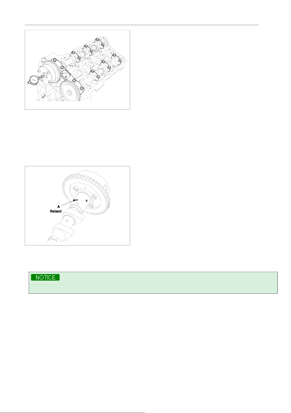
(2) Apply vinyl tape to the retard hole except the one indicated by the arrow in the illustration.
(3) Wind tape around the tip of the air gun and apply air of approx. 150kpa(1.5kgf/cm!, 21psi) to the port of the
camshaft.
(Perform this order to release the lock pin for the maximum delay angle locking.)
When the oil splashes, wipe it off with a shop rag.
(4) Under the condition of (3), turn the CVVT assembly to the advance angle side (the arrow marked direction in
the illustration) with your hand.
Depending on the air pressure, the CVVT assembly will turn to the advance side without applying force by
hand. Also, If excessive air leaks from the port, the lock pin may not be fully released.
Page 31

(5) Except the position where the lock pin meets at the maximum delay angle, let the CVVT assembly turn back
and forth and check the movable range and that there is no resistance to movement.
Standard: Movable smoothly in the range about 22.5°
(6) Turn the CVVT assembly with your hand and lock it at the maximum delay angle position (counter clockwise).
REASSEMBLY
Thoroughly clean all parts to be assembled.
Before installing the parts, apply fresh engine oil to all sliding and rotating surfaces.
Replace oil seals with new ones.
1. Install valves.
(1) Using SST(09222-3C100), push in a new oil seal.
Do not reuse old valve stem seals.
Incorrect installation of the seal could result in oil leakage past the valve guides.
(2) Install the valve, valve spring and spring retainer.
Place valve springs so that the side coated with enamel faces toward the valve spring retainer and then
installs the retainer.
(3) Using the SST(09222 - 3K000, 09222-3C300), compress the spring and install the retainer locks. After
installing the valves, ensure that the retainer locks are correctly in place before releasing the valve spring
compressor.
Page 32

(4) Lightly tap the end of each valve stem two or three times with the wooden handle of a hammer to ensure
proper seating of the valve and retainer lock.
2. Install MLAs.
Check that the MLA rotates smoothly by hand.
MLA can be reinstalled in its original position.
3. Install OCV(A).
Tightening torque
9.80 ~ 11.76Nm(1.0 ~ 1.2kgf.m, 7.23 ~ 8.68lb-ft)
• To install OCV with gray colored connector into RH bank.
• To install OCV with black colored connector into LH bank.
Page 33

• Do not reuse the OCV when dropped.
• Keep the OCV assembly clean.
• Do not hold the OCV sleeve during servicing.
• When the OCV is installed on the engine, do not move the engine by holding the OCV yoke.
INSTALLATION
• Thoroughly clean all parts to be assembled.
• Always use a new head and manifold gasket.
• The cylinder head gasket is a metal gasket. Take care not to bend it.
• Rotate the crankshaft, set theNo.1 piston at TDC.
1. Install the cylinder head.
A. The sealant locations on cylinder head and cylinder block must be free from contamination.
B. Apply sealant on cylinder block top face before assembling cylinder head gaskets.
The part must be assembled within 5 minutes after sealant was applied.
Refer to below illustration to apply the sealant.
Bead width : 2.0~3.0 mm
Sealant locations : 1.0~1.5mm from block surface
Recommended sealant :Liquid sealant TB1217H
Page 34

C. Apply sealant on cylinder head gaskets after assembling cylinder head gaskets on cylinder block.
The part must be assembled within 5 minutes after sealant was applied.
Be careful of the installation direction.
D. Install the cylinder head.
Remove the extruded sealant after assembling cylinder heads.
Page 35

2. Place the cylinder head carefully in order not to damage the gasket with the bottom part of the end.
3. Install cylinder head bolts.
(1) Do not apply engine oil on the threads and under the heads of the cylinder head bolts.
(2) Using SST(09221-4A000), install and tighten the cylinder head bolts and plate washers, in several passes, in
the sequence shown.
Tightening torque
Head bolt : 37.3~41.2Nm (3.8~4.2kgf.m, 27.5~30.4lb-ft) + 118~122° + 88~92°
Bolt (A) : 18.62 ~ 23.52Nm(1.9 ~ 2.4kgf.m, 13.74 ~ 17.36lb-ft)
Always use new cylinder head bolt.
Page 36

4. Install the CVVT and camshaft sprocket.
Tightening torque
64.68 ~ 76.44Nm(6.6 ~ 7.8 kgf.m, 47.74 ~ 56.4lb-ft)
• Install camshaft-inlet to dowel pin of CVVT assembly .
Ensure that the camshaft oil inlet is not obstructed.
• Hold the hexagonal head wrench portion of the camshaft with a vise, and install the bolt and CVVT
assembly.
• Do not rotate CVVT assembly when camshaft is installed to dowel pin of CVVT assembly.
5. Install camshafts(A).
• Apply a light coat of engine oil on camshaft journals.
• Assemble the key groove of camshaft rear side to the same level of head top surface.
• Ensure that the camshaft components are installed in the correct locations.
Page 37

Intake camshaft
LH RH
A: 30mm(1.1811in.)
B: 27mm(1.0630in.)
A: 27mm(1.0630in.)
B: 30mm(1.1811in.)
Exhaust camshaft
LH RH
A: 27mm(1.0630in.) A: 30mm(1.1811in.)
6. Install camshaft bearing caps.
Assemble camshaft bearing caps as the order below.
Tightening torque
5.9Nm(0.6kgf.m, 4.3lb-ft) - 1st step
9.80 ~ 11.76Nm(1.0 ~ 1.2kgf.m, 7.23 ~ 8.68lb-ft) - 2nd step
Page 38

Ensure that the cam bearing caps are installed in the correct location and direction. Refer to the table below.
A : L(LH),R(RH)
B : I(Intake),None(Exhaust)
C : Journal number
D : Front mark
Tightening torque
5.9Nm(0.6kgf.m, 4.3lb-ft) - 1st step
9.80 ~ 11.76Nm(1.0 ~ 1.2kgf.m, 7.23 ~ 8.68lb-ft) - 2nd step
Rotate the crankshaft not to contact the valves to the pistons by making the pistons below 10mm(0.3937in.)
from the top of cylinder block.
7. Install water temperature control assembly.
8. Install timing chain.
9. Check and adjust valve clearance.
10. Install the exhaust manifold.
11. Install the intake manifold.
Page 39

Engine Mechanical System
Engine And Transaxle Assembly
Engine Mechanical System
Page 40

2009 > G 3.8 DOHC >
REMOVAL
• Use fender covers to avoid damaging painted surfaces.
• To avoid damage, unplug the wiring connectors carefully while holding the connector portion.
• Mark all wiring and hoses to avoid misconnection.
1. Remove the engine cover(A).
2. Recover refrigerant, opening the high & low pressure pipe caps and connecting the refrigerant station(Refer to HA
group).
3. Disconnect the neagative terminal from the battery and remove the battery(A).
4. Remove the intake air hose and air cleaner assembly.
(1) Disconnect the MAF connector(A).
(2) Disconnect the breather hose(B) from air cleaner hose.
(3) Remove the intake air hose and air cleaner assembly(C).
Page 41

5. Remove the battery tray(A).
6. Remove the radiator grille upper cover(A).
7. Disconnect the RH and LH oxygen sensor connectors(A, B).
Page 42

8. Remove the radiator upper and lower hoses(A).
9. Disconnect the automatic transaxle fluid cooler hoses(A).
10. Disconnect the high and low pressure pipes from the radiator or the compressor.
11. Disconnect engine wiring.
(1) Remove the engine room fuse and relay box cover(A).
(2) Disconnect the PCM connectors(B).
(3) Disconnect the FAM connectors(C)(Refer to HA group).
Page 43

(4) Unscrew the FAM mounting bolts(D-3EA) and take the FAM(E) out of the splash shield(F).
(5) Disconnect the connector(G) from the splash shield(B).
12. Disconnect the transaxle wire harness connector and remove the transaxle control cable(Refer to TR group).
13. Remove heater hose(A).
14. Remove the brake vacuum hose(A).
Page 44

15. Remove power steering pump hose(Refer to ST group).
16. Remove front wheels(Refer to DS group).
17. Remove the radiator grille upper cover(A) for convenience sake.
18. Disconnect the power steering return hose(A).
19. Remove the radiator support upper member assembly(A) for convenience sake.
Page 45

The bottom side bolt(A) which can be seen after removing the under cover should be loosened for removal of
the radiator support upper member assembly.
20. Remove the under cover(A).
21. Drian engine oil.
22. Coolant should be drained before heater hose removal.
23. Remove front exhaust pipe(A).
24. Disconnect the wheel speed sensor and the stabilizer bar link(Refer to SS group).
25. Remove the caliper assembly and suspend it with a wire(Refer to DS group).
26. Supporting the engine and transaxle assembly with sub frame, remove the engine mounting bracket(A).
Page 46

27. Remove the transaxle insulator mounting bolt(A).
28. Supporting the engine and transaxle assembly with a jack, remove the sub frame with the engine and transaxle
assembly.
When remove the engine and transaxle assembly, be careful not to damage any surrounding parts or body
components.
INSTALLATION
Installation is in the reverse order of removal.
Perform the following :
• Adjust the shift cable.
• Refill the engine with engine oil.
• Refill the transaxle with fluid.
• Refill the radiator with engine coolant.
• Bleed air from the cooling system with the heater valve open.
• Clean the battery posts and cable terminals with sandpaper assemble them, then apply grease to prevent
corrosion.
• Inspect for fuel leakage.
After assembling the fuel line, turn on the ignition switch (do not operate the starter) so that the fuel pump runs for
approximately two seconds and fuel line pressurizes.
Repeat this operation two or three times, then check for fuel leakage at any point in the fuel line.
Page 47

Engine Mechanical System
Cylinder Block
Engine Mechanical System
Page 48

2009 > G 3.8 DOHC >
COMPONENTS
Page 49

Page 50

2009 > G 3.8 DOHC >
REMOVAL
• Use fender covers to avoid damaging painted surfaces.
• To avoid damage, unplug the wiring connectors carefully while holding the connector portion.
• Mark all wiring and hoses to avoid misconnection.
• Inspection the timing belt before removing the cylinder head.
• Turn the crankshaft pulley so that the No.1 piston is at top dead center.
• Engine removal is required for this procedure.
1. Remove exhaust manifold.
2. Remove intake manifold.
3. Remove timing chain.
4. Remove water temperature control assembly.
5. Remove cylinder head.
6. Remove oil pump.
7. Remove oil filter assembly.
8. Remove A/C compressor(A) from engine.
9. Remove generator(A) from engine.
10. Remove power steering pump(A) from engine.
Page 51

DISASSEMBLY
1. Remove drive plate.
2. Remove knock sensor(A).
3. Remove upper oil pan(A).
4. Remove baffle plate(A).
5. Remove rear oil seal case(A).
Page 52

6. Remove oil drain cover(A).
7. Check the connecting rod end play.
8. Check the connecting rod cap oil clearance.
9. Remove piston and connecting rod assemblies.
(1) Using a ridge reamer, remove all the carbon from the top of the cylinder.
(2) Push the piston, connecting rod assembly and upper bearing through the top of the cylinder block.
• Keep the bearings, connecting rod and cap together.
• Arrange the piston and connecting rod assemblies in the correct order.
10. Remove crankshaft main bearing cap and check oil clearance.
11. Check the crankshaft end play.
12. Lift the crankshaft(A) out of engine, being careful not to damage journals.
Page 53

Arrange the main bearings and thrust bearings in the correct order.
13. Check fit between piston and piston pin.
Try to move the piston back and forth on the piston pin. If any movement is felt, replace piston and piston pin as a
set.
14. Remove piston rings.
(1) Using a piston ring expender, remove the 2 compression rings.
(2) Remove 2 side rails and the spacer by hand.
Arrange the piston rings in the correct order only.
15. Disconnect connecting rod from piston.
Using a press, remove the piston pin from piston.
(Press-in load : 800 ~ 1400kg (1764 ~ 3086lb)
INSPECTION
CONNECTING ROD AND CRANKSHAFT
1. Check the connecting rod end play.
Using a feeler gauge, measure the end play while moving the connecting rod back and forth.
Standard end play : 0.1~ 0.25mm(0.004 ~ 0.010in.)
A. If out-of-tolerance, install a new connecting rod.
Page 54

B. If still out-of-tolerance, replace the crankshaft.
2. Check the connecting rod bearing oil clearance.
(1) Check the matchmarks on the connecting rod and cap are aligned to ensure correct reassembly.
(2) Remove 2 connecting rod cap bolts.
(3) Remove the connecting rod cap and bearing half.
(4) Clean the crank pin and bearing.
(5) Place plastigage across the crank pin.
(6) Reinstall the bearing half and cap, and torque the bolts.
Tightening torque
17.7~21.6Nm (1.8~2.2kgf.m, 13.0~15.9lb-ft) + 88~92°
Do not turn the crankshaft.
(7) Remove 2 bolts, connecting rod cap and bearinghalf.
(8) Measure the plastigage at its widest point.
Standard oil clearance
0.038 ~ 0.056mm(0.0015 ~ 0.0022in.)
(9) If the plastigage measures too wide or too narrow, remove the upper half of the bearing, install a new,
complete bearing with the same color mark (select the color as shown in the next column), and recheck the
clearance.
Do not file, shim, or scrape the bearings or the caps to adjust clearance.
(10) If the plastigage shows the clearance is still incorrect, try the next larger or smaller bearing (the color listed
above or below that one), and check clearance again.
If the proper clearance cannot be obtained by using the appropriate larger or smaller bearings, replace
the crankshaft and start over.
If the marks are indecipherable because of an accumulation of dirt and dust, do not scrub them with a
wire brush or scraper. Clean them only with solvent or detergent.
Page 55

CONNECTING ROD MARK LOCATION
DISCRIMINATION OF CONNECTING ROD
CLASS MARK INSIDE DIAMETER
0 a
58.000 ~ 58.006mm
(2.2834 ~ 2.2837in.)
1 b
58.006 ~ 58.012mm
(2.2837 ~ 2.2839in.)
2 c
58.012 ~ 58.018mm
(2.2839 ~ 2.2842in.)
CRANKSHAFT PIN MARK LOCATION
DISCRIMINATION OF CRANKSHAFT
DISCRIMINATION OF CRANKSHAFT
CLASS MARK OUTSIDE DIAMETER OF PIN
I 1 or A
54.966 ~ 54.972mm
(2.1640 ~ 2.1642in.)
II 2 or B
54.960 ~ 54.966mm
(2.1638 ~ 2.1640in.)
III 3 or C
54.954 ~ 54.960mm
(2.1635 ~ 2.1638in.)
PLACE OF IDENTIFICATION MARK (CONNECTING ROD BEARING)
Page 56

DISCRIMINATION OF CONNECTING ROD BEARING
CLASS MARK THICKNESS OF BEARING
E BLUE
1.514 ~ 1.517mm
(0.0596 ~ 0.0597in.)
D BLACK
1.511 ~ 1.514mm
(0.0595 ~ 0.0596in.)
C BROWN
1.508 ~ 1.511mm
(0.0594 ~ 0.0595in.)
B GREEN
1.505 ~ 1.508mm
(0.0593 ~ 0.0594in.)
A YELLOW
1.502 ~ 1.505mm
(0.0591 ~ 0.0593in)
(11) Selection
CONNECTING ROD IDENTIFICATION MARK
0(a) 1(b) 2(c)
CRANKSHAFT
INDENTIFICATION
MARK
1 or A
A
(YELLOW)
B
(GREEN)
C
(BROWN)
2 or B
B
(GREEN)
C
(BROWN)
D
(BLACK)
3 or C
C
(BROWN)
D
(BLACK)
E
(BLUE)
3. Check the crankshaft bearing oil clearance.
(1) To check main bearing-to-journal oil clearance, remove the main bearing caps and bearing halves.
(2) Clean each main journal and bearing half with a clean shop tower.
(3) Place one strip of plastigage across each main journal.
(4) Reinstall the bearings and caps, then torque the bolts.
Tightening torque
49.00Nm(5.0 kgf.m, 36.16lb-ft) + 90°
19.60 Nm(2.0 kgf.m, 14.46lb-ft)+ 120°
29.40 ~ 31.36Nm(3.0 ~ 3.2 kgf.m, 21.70 ~ 23.14lb-ft)
Do not turn the crankshaft.
Page 57

(5) Remove the cap and bearing again, and measure the widest part of the plastigage.
Standard oil clearance
0.022 ~ 0.040mm (0.0009 ~ 0.0016in.)
(6) If the plastigage measures too wide or too narrow, remove the upper half of the bearing, install a new,
complete bearing with the same color mark (select the color as shown in the next column), and recheck the
clearance.
Do not file, shim, or scrape the bearings or the caps to adjust clearance.
(7) If the plastigage shows the clearance is still incorrect, try the next larger or smaller bearing (the color listed
above or below that one), and check clearance again.
If the proper clearance cannot be obtained by using the appropriate larger or smaller bearings, replace the
crankshaft and start over.
If the marks are indecipherable because of an accumulation of dirt and dust, do not scrub them with a wire
brush or scraper. Clean them only with solvent or detergent.
Crankshaft bore mark location
Letters have been stamped on the block as a mark for the size of each of the 5 main journal bores.
Use them, and the numbers or bar stamped on the crank (marks for main journal size), to choose the correct
bearings.
DISCRIMINATION OF CYLINDER BLOCK
CLASS MARK INSIDE DIAMETER
73.500 ~ 73.506mm
Page 58

a A
(2.8937 ~ 2.8939in.)
b B
73.506 ~ 73.512mm
(2.8939 ~ 2.8942in.)
c C
73.512 ~ 73.518mm
(2.8942 ~ 2.8944in.)
CRANKSHAFT JOURNAL MARK LOCATION
DISCRIMINATION OF CRANKSHAFT
DISCRIMINATION OF CRANKSHAFT
CLASS MARK OUTSIDE DIAMETER OF JOURNAL
I 1 or A
68.954 ~ 68.960mm
(2.7147 ~ 2.7150in.)
II 2 or B
68.948 ~ 68.954mm
(2.7145 ~ 2.7147in.)
III 3 or C
68.942 ~ 68.948mm
(2.7142 ~ 2.7145in.)
PLACE OF IDENTIFICATION MARK (CRANKSHAFT BEARING)
DISCRIMINATION OF CRANKSHAFT BEARING
CLASS MARK THICKNESS OF BEARING
E BLUE
2.277 ~ 2.280mm
(0.0896 ~ 0.0897in.)
D BLACK
2.274 ~ 2.277mm
(0.0895 ~ 0.0896in.)
C BROWN
2.271 ~ 2.274mm
(0.0894 ~ 0.0895in.)
Page 59

B GREEN
2.268 ~ 2.271mm
(0.0893 ~ 0.0894in.)
A YELLOW
2.265 ~ 2.268mm
(0.0892 ~ 0.0893in.)
SELECTION
CRANKSHAFT BORE IDENTIFICATION MARK
a(A) b(B) c(C)
CRANKSHAFT
IDENTIFICATION MARK
1 or A
A
(YELLOW)
B
(GREEN)
C
(BROWN)
2 or B
B
(GREEN)
C
(BROWN)
D
(BLACK)
3 or C
C
(BROWN)
D
(BLACK)
E
(BLUE)
4. Check crankshaft end play.
Using a dial indicator, measure the thrust clearance while prying the crankshaft back and forth with a screwdriver.
Standard end play
0.10 ~ 0.28mm (0.0039 ~ 0.0110in.)
If the end play is greater than maximum, replace the thrust bearings as a set.
Thrust bearing thickness
2.41 ~ 2.45mm(0.0949 ~ 0.0964in.)
Standard end play
0.10 ~ 0.28mm (0.0039 ~ 0.0110in.)
5. Inspect main journals and crank pins
Using a micrometer, measure the diameter of each main journal and crank pin.
Main journal diameter : 68.942 ~ 68.960mm (2.7142 ~ 2.7149in.)
Crank pin diameter : 54.954 ~ 54.972mm (2.1635 ~ 2.1642in.)
Page 60

CONNECTING RODS
1. When reinstalling, make sure that cylinder numbers put on the connecting rod and cap at disassembly match. When
a new connecting rod is installed, make sure that the notches for holding the bearing in place are on the same
side.
2. Replace the connecting rod if it is damaged on the thrust faces at either end. Also if step wear or a severely rough
surface of the inside diameter of the small end is apparent, the rod must be replaced as well.
3. Using a connecting rod aligning tool, check the rod for bend and twist. If the measured value is close to the repair
limit, correct the rod by a press. Any connecting rod that has been severely bent or distorted should be replaced.
Allowable bend of connecting rod :
0.05mm / 100mm (0.0020 in./3.94 in.) or less
Allowable twist of connecting rod :
0.1mm / 100mm (0.0039 in./3.94 in.) or less
CYLINDER BLOCK
1. Remove gasket material.
Using a gasket scraper, remove all the gasketmaterial from the top surface of the cylinder block.
2. Clean cylinder block
Using a soft brush and solvent, thoroughly clean the cylinder block.
3. Inspect top surface of cylinder block for flatness.
Using a precision straight edge and feeler gauge, measure the surface contacting the cylinder head gasket for
warpage.
Flatness of cylinder block gasket surface
Standard : Less than 0.05mm(0.0020 in.),Less than 0.02mm(0.0008in.) / 150 x 150
Page 61

4. Inspect cylinder bore diameter
Visually check the cylinder for vertical scratchs.
If deep scratches are present, replace the cylinder block.
5. Inspect cylinder bore diameter
Using a cylinder bore gauge, measure the cylinder bore diameter at position in the thrust and axial directions.
Standard diameter
96.00 ~ 96.03mm (3.7795 ~ 3.7807in.)
6. Check the cylinder bore size code on the cylinder block.
Class Size code Cylinder bore inner diameter
Page 62

A A
96.00~96.01mm
(3.7795 ~ 3.7799in.)
B B
96.01~96.02mm
(3.7799 ~ 3.7803in.)
C C
96.02~96.03mm
(3.7803 ~ 3.7807in.)
7. Check the piston size code on the piston top face.
Class Size code Piston outer diameter
A A
95.96~95.97mm
(3.7779 ~ 3.7783in.)
B B
95.97~95.98mm
(3.7783 ~ 3.7787in.)
C C
95.98~95.99mm
(3.7787 ~ 3.7791in.)
8. Select the piston related to cylinder bore class.
Clearance : 0.03 ~ 0.05mm(0.0012 ~ 0.0020in.)
PISTON AND RINGS
1. Clean piston
(1) Using a gasket scraper, remove the carbon from the piston top.
(2) Using a groove cleaning tool or broken ring, clean the piston ring grooves.
(3) Using solvent and a brush, thoroughly clean the piston.
Do not use a wire brush.
2. The standard measurement of the piston outside diameter is taken 14 mm (0.5512 in.) from the bottom of the
piston.
Standard diameter
95.96 ~ 95.99mm (3.7779~ 3.7791in.)
Page 63

3. Calculate the difference between the cylinder bore diameter and the piston diameter.
Piston-to-cylinder clearance
0.03 ~ 0.05mm(0.0012 ~ 0.0020in.)
4. Inspect the piston ring side clearance.
Using a feeler gauge, measure the clearance between new piston ring and the wall of the ring groove.
Piston ring side clearance
Standard
No.1 : 0.03 ~ 0.07mm (0.0012 ~ 0.0027in.)
No.2 : 0.03 ~ 0.07mm (0.0012 ~ 0.0027in.)
Oil ring : 0.06 ~ 0.15mm (0.0024 ~ 0.0059in.)
Limit
No.1 : 0.1mm (0.004in.)
No.2 : 0.1mm (0.004in.)
Oil ring : 0.2mm (0.008in.)
If the clearance is greater than maximum, replace the piston.
5. Inspect piston ring end gap.
To measure the piston ring end gap, insert a piston ring into the cylinder bore. Position the ring at right angles to
the cylinder wall by gently pressing it down with a piston. Measure the gap with a feeler gauge. If the gap exceeds
the service limit, replace the piston ring. If the gap is too large, recheck the cylinder bore diameter. If the bore is
over the service limit, the cylinder block must be replaced.
Piston ring end gap
Standard
No.1 : 0.17 ~ 0.32mm (0.0067 ~ 0.0126in.)
No.2 : 0.32 ~ 0.47m (0.0126 ~ 0.0185in.)
Oil ring : 0.20 ~ 0.70mm (0.0079 ~ 0.0275in.)
Limit
No.1 : 0.6mm (0.0236in.)
No.2 : 0.7mm (0.0275in.)
Oil ring : 0.8mm (0.0315in.)
Page 64

PISTON PINS
1. Measure the diameter of the piston pin.
Piston pin diameter
23.002 ~ 23.006mm (0.9056 ~ 0.9057in.)
2. Measure the piston pin-to-piston clearance.
Piston pin-to-piston clearance
0.009 ~ 0.017mm (0.0004 ~ 0.0007in.)
3. Check the difference between the piston pin diameter and the connecting rod small end diameter.
Piston pin-to-connecting rod interference
-0.032 ~ -0.017mm (-0.0012 ~ -0.0007in.)
REASSEMBLY
• Thoroughly clean all parts to assembled.
• Before installing the parts, apply fresh engine oil to all sliding and rotating surfaces.
• Replace all gaskets, O-rings and oil seals with new parts.
1. Assemble piston and connecting rod.
(1) Use a hydraulic press for installation.
(2) The piston front mark and the connecting rod front mark must face the timing belt side of the engine.
Page 65

2. Install piston rings.
(1) Install the oil ring spacer and 2 side rails by hand.
(2) Using a piston ring expander, install the 2 compression rings with the code mark facing upward.
(3) Position the piston rings so that the ring ends are as shown.
3. Install connecting rod bearings.
(1) Align the bearing claw with the groove of the connecting rod or connecting rod cap.
(2) Install the bearings(A) in the connecting rod and connecting rod cap(B).
4. Install main bearings.
Upper bearings have an oil groove of oil holes; Lower bearings do not.
(1) Align the bearing claw with the claw groove of the cylinder block, push in the 4 upper bearings.
(2) Align the bearing claw with the claw groove of the main bearing cap, and push in the 4 lower bearings(A).
Page 66

5. Install thrust bearings.
Install the 2 thrust bearings(A) under the No.3 journal position of the cylinder block with the oil grooves facing
outward.
6. Place crankshaft on the cylinder block.
7. Place main bearing caps on cylinder block.
8. Install main bearing cap bolts.
(1) Install and uniformly tighten the bearing cap bolts, in several passes, in the sequence shown.
Tightening torque
Main bearing cap bolt
49.00Nm(5.0 kgf.m, 36.16lb-ft) + 90° (1 ~ 8)
19.60 Nm(2.0 kgf.m, 14.46lb-ft)+ 120° (9 ~ 16)
29.40 ~ 31.36Nm(3.0 ~ 3.2 kgf.m, 21.70 ~ 23.14lb-ft) (17 ~ 22)
Page 67

• Always use new main bearing cap bolt.
• If any of the bearing cap bolts in broken or deformed, replace it.
Use SST( 09221-4A000 ), install main bearing cap bolts.
(2) Check that the crankshaft turns smoothly.
9. Check crankshaft end play.
10. Install piston and connecting rod assemblies.
Before installing the pistons, apply a coat of engine oil to the ring grooves and cylinder bores.
(1) Install the ring compressor, check that the bearing is securely in place, then position the piston in the cylinder,
and tap it in using the wooden handle of a hammer.
(2) Stop after the ring compressor pops free, and check the connecting rod-to-check journal alignment before
pushing the piston into place.
(3) Apply engine oil to the bolt threads. Install the rod caps with bearings, and torque the bolts.
Tightening torque
17.7~21.6Nm (1.8~2.2kgf.m, 13.0~15.9lb-ft) + 88~92°
Use SST(09221-4A000), install connecting rod bearing cap bolts.
Page 68

• Always use new connecting rod bearing cap bolt.
• Maintain downward force on the ring compressor to prevent the rings from expanding before entering
the cylinder bore.
11. Check the connecting rod end play.
12. Install oil drain cover.
Tightening torque
9.80 ~ 11.76Nm (1.0 ~ 1.2kgf.m, 7.23 ~ 8.68b-ft)
• Ensure the sealing face is clean before assembling two parts.
Page 69

• Remove harmful foreign matters on the sealing face before applying sealant
• Be assembling oil drain cover, the liquid sealant TB1217H should be applied oil drain cover.
• The part must be assembled within 5 minutes after sealant was applied.
• Apply sealant to the inner threads of the bolt holes.
13. Install rear oil seal case.
Tightening torque
9.80 ~ 11.76Nm (1.0 ~ 1.2kgf.m, 7.23 ~ 8.67lb-ft)
• Make clean the sealing face before assembling two parts.
• Remove harmful foreign matters on the sealing face before applying sealant
• Be assembling rear oil seal case, the liquid sealant TB1217H should be applied rear oil seal case.
• The part must be assembled within 5 minutes after sealant was applied.
• Apply sealant to the inner threads of the bolt holes.
14. Using SST(09231-3C200, 09231-H1100), install rear oil seal.
Page 70

15. Install baffle plate.
Install and uniformly tighten the baffle plate bolts, in several passes, in the sequence shown.
Tightening torque
9.80 ~ 11.76Nm (1.0 ~ 1.2kgf.m, 7.23 ~ 8.68lb-ft)
16. Install upper oil pan.
A. Using a gasket scraper, remove all the old packing material from the gasket surfaces.
B. Before assebling the oil pan, the liquid sealant TB1217H should be applied on upper oil pan.
The part must be assembled within 5 minutes after the sealant was applied.
Bead width : 2.5mm(0.1in.)
• Ensure the sealing face is clean before assembling two parts.
• Remove harmful foreign matters on the sealing face before applying sealant
• When applying sealant gasket, sealant must not be protruded into the inside of oil pan.
• To prevent leakage of oil, apply sealant gasket ot the inner threads of the bolt holes.
Page 71

C. Install upper oil pan.
Uniformly tighten the bolts in several passes.
Tightening torque
9.80 ~ 11.76Nm (1.0 ~ 1.2kgf.m, 7.23 ~ 8.68lb-ft)
17. Install knock sensor.
Tightening torque
15.68 ~ 23.52Nm (1.6 ~ 2.4kgf.m, 11.57 ~ 17.36lb-ft)
18. Install drive plate.
Tightening torque
71.54 ~ 75.46Nm (7.3 ~ 7.7kgf.m, 52.80 ~ 55.69lb-ft)
INSTALLATION
1. Install power steering pump.
2. Install generator.
3. Install air conditioner compressor
4. Install oil filter assembly.
5. Install oil pump.
6. Install cylinder head.
7. Install water temperature control assembly.
8. Install timing chain.
9. Install intake manifold.
10. Install exhaust manifold.
Page 72

Engine Mechanical System
Cooling System
Engine Mechanical System
Page 73

2009 > G 3.8 DOHC >
ENGINE COOLANT REFILLING AND BLEEDING
Never remove the radiator cap when the engine is hot. Serious scalding could be caused by hot fluid under high
pressure escaping from the radiator.
When pouring engine coolant, be sure to shut the relay box lid and not to let coolant spill on the electrical parts or
the paint. If any coolant spills, rinse it off immediately.
1. Make sure the engine and radiator are cool to the touch.
2. Remove radiator cap.
3. Loosen the drain plug, and drain the coolant.
4. Tighten the radiator drain plug securely.
5. Remove, drain and reinstall the reservoir. Fill the tank halfway to the "F" mark with water, then up to the "F" mark
with antifreeze.
6. Fill fluid mixture with coolant and water(4 : 6) slowly through the radiator cap. Push the upper/lower hoses of the
radiator to ensure proper air bleeding.
• Use only genuine antifreeze/coolant.
• For best corrosion protection, the coolant concentration must be maintained year-round at 50% minimum.
Coolant concentrations less than 50% may not provide sufficient protection against corrosion or freezing.
• Coolant concentrations greater then 60% will impair cooling efficiency and are not recommended.
• Do not mix different brands of antifreeze/coolants.
• Do not use additional rust inhibitors or antirust products; they may not be compatible with the coolant.
7. Start the engine.
When the cooling fan operates and coolant circulates, refill coolant through the radiator cap.
8. Repeat 7 until the cooling fan cycles 3 ~ 5times and bleed air sufficiently out of the cooling system.
9. Install the radiator cap and fill the reservoir tank to the "MAX" line with coolant.
10. Run the vehicle under idle until the cooling fan operates 2 ~ 3 times.
11. Stop the engine and wait until the cooling system is cool to the touch.
12. Repeat 6 to 11 until the coolant level doesn't fall any more, bleed air out of the cooling system.
Proper cooling system operation depends on the absence of trapped air within the system. It is essential that
the cooling system be properly filled and bled before returning the vehicle to service.
CAP TESTING
1. Remove the radiator cap, wet its seal with engine coolant, then install it no pressure tester.
Page 74

2. Apply a pressure of 93 ~ 123kPa (0.95 ~ 1.25kgf/cm!, 14 ~ 19psi)
3. Check for a drop in pressure.
4. If the pressure drops, replace the cap.
TESTING
1. Wait until engine is cool, then carefully remove the radiator cap and fill the radiator with engine coolant, then install
it on the pressure tester.
2. Apply a pressure tester to the radiator and apply a pressure of 93 ~ 123kPa (0.95 ~ 1.25kgf/cm! 14 ~18psi).
3. Inspect for engine coolant leaks and a drop in pressure.
4. Remove the tester and reinstall the radiator cap.
Check for engine oil in the coolant and/or coolant in the engine oil.
Page 75

2009 > G 3.8 DOHC >
COMPONENT
Page 76

Page 77

2009 > G 3.8 DOHC >
REMOVAL
WATER PUMP
1. Drain the engine coolant.
System is under high pressure when the engine is hot. To avoid danger of releasing scalding engine coolant,
remove the cap only when the engine is cool.
2. Remove drive belt(A).
3. Remove the 4 bolts and pump pulley(A).
4. Remove the water pump(A) and gasket.
WATER TEMPERATURE CONTROL ASSEMBLY
1. Drain the engine coolant.
2. Remove air cleaner assembly.
Page 78

3. Disconnect radiator upper and lower hose(A).
4. Disconnect ECT connector.
5. Disconnect heater hose, water vent hose and water hose from water temperature control assembly.
6. Remove wiring protector.
7. Remove water temperature control assembly(A).
THERMOSTAT
Removal of the thermostat would have an adverse effect, causing a lowering of cooling efficiency. Do not remove
the thermostat, even if the engine tends to overheat.
1. Drain engine coolant so its level is below thermostat.
2. Remove water inlet(A) and thermostat(B).
RADIATOR
1. Drain the engine coolant.
2. Remove the radiator grille upper cover(A).
Page 79

3. Remove the radiator support upper member assembly(A) for convenience sake.
The bottom side bolt(A) which can be seen after removing the under cover should be loosened for removal of
the radiator support upper member assembly.
4. Disconnect radiator upper and lower hoses(A).
5. Disconnect transaxle oil cooler hoses(A).(Refer to TR group)
Page 80

6. Disconnect the radiator fan connectors(A).
7. Disconnect the pressure lines(A) from the radiator assembly(B).
8. Seperate the condenser(A) from the radiator assembly(B) by removing the bolts(C).
Page 81

9. Remove the radiator bracket.
10. Remove the radiator assembly.
11. Remove the radiator cooling fan(A).
INSPECTION
WATER PUMP
1. Check each part for cracks, damage or wear, and replace the coolant pump assembly if necessary.
2. Check the bearing for damage, abnormal noise and sluggish rotation, and replace the coolant pump assembly if
necessary.
3. Check for coolant leakage. If coolant leaks from hole, the seal is malfunctioning. Replace the coolant pump
assembly.
A small amount of "weeping" from the bleed hole is normal.
THERMOSTAT
1. Immerse the thermostat in water and gradually heat the water.
Page 82

2. Check the valve opening temperature.
Valve opening temperature : 82°C (177°F)
Full opening temperature : 95°C (205°F)
If the valve opening temperature is not as specified, replace the thermostat.
3. Check the valve lift.
Valve lift : Min. 10mm (0.4in.) at 95°C (205°F)
If the valve lift is not as specified, replace the thermostat.
INSTALLATION
WATER PUMP
1. Install the water pump(A) and a new gasket(B) with 12 bolts.
Tightening torque
21.56 ~ 23.52Nm (2.2 ~ 2.4kgf.m, 15.91 ~ 17.36lb-ft)
9.80 ~ 11.76Nm (1.0 ~ 1.2kgf.m, 7.23 ~ 8.68lb-ft)
Make clean the contact face before assembly.
2. Install the 4 bolts and pump pulley(A).
Tightening torque
7.84 ~ 9.80Nm (0.8 ~ 1.0kgf.m, 5.78 ~ 7.23lb-ft)
Page 83

3. Install drive belt(A).
4. Fill with engine coolant.
5. Start engine and check for leaks.
6. Recheck engine coolant level.
WATER TEMPERATURE CONTROL ASSEMBLY
Make clean the contact face before assembly.
1. Install water temperature control assembly(B) and new gasket(A).
Tightening torque
18.62 ~ 23.52Nm (1.9 ~ 2.4kgf.m, 13.74 ~ 17.36lb-ft)
Use new O -rings(C) when reassembling.
Page 84

2. Connect water hoses to the water temperature control assembly.
3. Install wiring protector.
4. Connect ECT connector.
5. Connect radiator upper and lower hose(A).
6. Install air cleaner assembly.
7. Fill with engine coolant.
8. Start engine and check for leaks.
9. Recheck engine coolant level.
THERMOSTAT
1. Place thermostat in thermostat housing.
(1) Install the thermostat with the jiggle valve upward.
(2) Install a new thermostat(B).
2. Install water inlet(A).
Tightening torque
16.66 ~ 19.60Nm (1.7 ~ 2.0kgf.m, 12.30 ~ 14.47lb-ft)
3. Fill with engine coolant.
4. Start engine and check for leaks.
RADIATOR
1. Install the radiator fan(A) to the radiator.
Tightening torque
4.9 ~ 7.8Nm (0.5 ~ 0.8kgf.m, 3.6 ~ 5.8lb-ft)
Page 85

2. Install the radiator assembly to the vehicle.
3. Install the radiator bracket.
4. Fix the condenser with the radiator assembly.
Tightening torque
4.9 ~ 7.8Nm (0.5 ~ 0.8kgf.m, 3.6 ~ 5.8lb-ft) - D
6.9 ~ 9.8Nm (0.7 ~ 1.0kgf.m, 5.1 ~ 7.2lb-ft) - C
5. Connect the radiator fan connectors(A).
Page 86

6. Connect the pressure lines(A) to the radiator assembly(B).
7. Connect transaxle oil cooler hoses(A).(Refer to TR group)
8. Connect radiator upper and lower hoses(A).
9. Install the radiator support upper member assembly(A).
Page 87

10. Install the radiator grille upper cover(A).
11. Fill with engine coolant.
12. Start engine and check for leaks.
13. Recheck engine coolant level.
Page 88

Engine Mechanical System
Lubrication System
Engine Mechanical System
Page 89

2009 > G 3.8 DOHC >
OIL AND FILTER
• Prolonged and repeated contact with mineral oil will result in the removal of natural fats from the skin, leading
to dryness, irritation and dermatitis. In addition, used engine oil contains potentially harmful contaminants
which may cause skin cancer.
• Exercise caution in order to minimize the length and frequency of contact of your skin to used oil. Wear
protective clothing and gloves. Wash your skin thoroughly with soap and water, or use water-less hand
cleaner, to remove any used engine oil. Do not use gasoline, thinners, or solvents.
• In order to preserve the environment, used oil and used oil filter must be disposed of only at designated
disposal sites.
1. Park the car on level ground.
Start the engine and let it warm up.
2. Turn the engine off and open the hood.
Remove the engine cover.
3. Loosen the oil filter cap by turining it clockwise with SST (09263-3C100). Allow 5 minutes for the oil in the filter
assembly to drain.
4. Drain the engine oil.
A. Remove the oil filler cap.
B. After lifting the car, remove the oil drain plug and drain the oil into a container.
5. Replace oil filter.
A. Disconnect the oil filter cap from oil filter body.
B. Remove the oil filter element.
C. Check and clean the oil filter installation surface.
D. Check the part number of the new oil filter is as same as old one.
E. Install new oil filter element(A) and two new O-rings(B).
F. Apply clean engine oil to the new O-rings.
Page 90

Lightly screw the oil filter cap into place, and tighten it until the O -ring contacts the seat.
G. Finally tighten it again by specified tightening torque.
Tightening torque
24.50Nm (2.5kgf.m, 18.08lb-ft)
6. Refill with engine oil.
A. Install the oil drain plug with a new gasket.
Tightening torque
34.3 ~ 44.1Nm (3.5 ~ 4.5kgf.m, 25.3 ~ 32.5lb-ft)
B. Fill with fresh engine oil, after removing the engine oil level gauge.
Capacity
Total : 6.0 L (6.34 US qt, 5.27 lmp qt)
Oil pan : 5.5 L (5.81 US qt, 4.83 lmp qt)
Drain and refill including oil filter : 5.2 L (5.49 US qt, 4.57 lmp qt)
Oil quality : ABOVE API SJ / SL or SAE 5W-20
C. Install the oil filler cap and oil level gauge.
7. Start the engine and check to be sure no oil is leaking from the drain plug or oil filter.
8. Recheck engine oil level.
INSPECTION
1. Check engine oil quality.
Check the oil for deterioration, entry of water, discoloring or thinning.
If the quality is visibly poor, replace the oil.
2. Check engine oil level.
After warming up the engine and then 5 minutes after the engine stop, oil level should be between the "L" and "F"
marks on the dipstick.
If low, check for leakage and add oil up to the "F" mark.
Do not fill with engine oil above the "F" mark.
SELECTION OF ENGINE OIL
Recommended API classification : Above SJ or SL
Recommended SAE viscosity grades : 5W-20
If 5W-20 engine oil is not available, 5W-30 or secondary recommanded engine oil for carrespanding temperature
range can be used.
Page 91

For best performance and maximum protection of all types of operation, select only those lubricants which :
• Satisfy the requirement of the API classification.
• Have proper SAE grade number for expected ambient temperature range.
Lubricants that do not have both an SAE grade number and API service classification on the container should not
be used.
Page 92

2009 > G 3.8 DOHC >
COMPONENT
Page 93

2009 > G 3.8 DOHC >
REMOVAL
Oil pump
1. Drain engine oil.
2. Using SST(09215-3C000) remove lower oil pan(A).
Be careful not to damage the contact surfaces of upper oil pan and lower oil pan.
3. Remove oil pump chain cover(A).
4. Remove oil pump chain sprocket(A).
5. Remove oil pump(A).
Page 94

Oil filter assembly
1. Loosen the oil filter cap by turining it clockwise with SST (09263-3C100). Allow 5 minutes for the oil in the filter
assembly to drain.
2. Remove surge tank and intake manifold.
3. Disconnect oil pressure switch connector.
4. Drain the engine coolant.
5. Disconnect water hoses from ETC.
6. Remove water temperature control assembly.
7. Disconnect water vent hose(A).
8. Remove oil filter body cover(B).
9. Remove oil filter body.(A).
Be careful of the knock sensor connector.
INSPECTION
Page 95

OIL PRESSURE SWITCH
1. Check the continuity between the terminal and the body with an ohmmeter.
If there is no continuity, replace the oil pressure switch.
2. Check the continuity between the terminal and the body when the fine wire is pushed. If there is continuity even
when the fine wire is pushed, replace the switch.
3. If there is no continuity when a 50kpa (7psi) is applied throgh the oil hole, the switch is operaing properly.
Check for air leakage. If air leaks, the diaphragm is broken. Replace it.
INSTALLATION
Oil pump
1. Install oil pump(A).
Tightening torque
19.6 ~ 23.5Nm (2.0 ~ 2.4kgf.m, 14.5 ~ 17.4lb-ft)
Always use a new O-ring(B).
Page 96

2. Install oil pump sprocket(A)and oil pump chain on the oil pump.
Tightening torque
18.62 ~ 21.56Nm (1.9 ~ 2.2kgf.m, 13.74 ~ 15.91lb-ft)
3. Install oil pump chain cover(A).
Tightening torque
9.80 ~ 11.76Nm (1.0 ~ 1.2kgf.m, 7.23 ~ 8.68lb-ft)
4. Install lower oil pan.
A. Using a gasket scraper, remove all the old packing material from the gasket surfaces.
B. Before assembling the oil pan, the liquid sealant TB1217H should be applied on upper oil pan.
The part must be assembled within 5 minutes after the sealant was applied.
Bead width : 2.5mm(0.1in.)
But marked area(*) to be 5.0mm(0.2in.)
Page 97

• Ensure the sealing face is clean before assembling two parts.
• Remove harmful foreign matters on the sealing face before applying sealant
• When applying sealant gasket, sealant must not be protruded into the inside of oil pan.
• To prevent leakage of oil, apply sealant gasket ot the inner threads of the bolt holes.
C. Install lower oil pan.
Uniformly tighten the bolts in several passes.
Tightening torque
9.80 ~ 11.76Nm (1.0 ~ 1.2kgf.m, 7.23 ~ 8.68lb-ft)
D. After assembly, wait at least 30 minutes before filling the engine with oil.
OIL FILTER ASSEMBLY
1. Install oil filter body(A) and new O -rings.
Tightening torque
9.80 ~ 11.76Nm (1.0 ~ 1.2kgf.m, 7.23 ~ 8.68lb-ft)
• All rubber gasket must be no damaged by assembling parts.
• Be careful of the knock sensor connector.
• Always use a new O-ring
2. Install oil filter body cover(B) and new gasket on the oil filter body.
Tightening torque
9.80 ~ 11.76Nm (1.0 ~ 1.2kgf.m, 7.23 ~ 8.68lb-ft)
Page 98

3. Connect water vent hose(A)
Tightening torque
9.80 ~ 11.76Nm (1.0 ~ 1.2kgf.m, 7.23 ~ 8.68lb-ft)
4. Install water temperature control assembly.
5. Connect water hoses on the ETC.
6. Connect oil pressure switch connector.
7. Install intake manifold and surge tank.
8. Fill with engine coolant.
9. Start engine and check for leaks.
10. Recheck engine coolant level.
Page 99

Engine Mechanical System
Intake & Exhaust System
Engine Mechanical System
Page 100

2009 > G 3.8 DOHC >
COMPONENT
 Loading...