

Page 1
Before using this Compact Static Eliminator, be sure to
thoroughly read this Instruction Manual.
After you are finished with this Instruction Manual, be
sure to store it in a safe place for quick reference.
High-performance Micro Static Eliminatior
Instruction Manual
SJ-M
96M10103
1
Page 2
Preface
This document describes handling, method of operation and precautions when using the Compact
Spot-type Static Eliminator SJ-M 300 Series. Before you start to use the SJ-M 300 Series, be sure to
thoroughly read this document in order to make full use and safely use its functions.
Store this document in a safe place so that you can retrieve it whenever necessary.
■ Symbols
This manual uses the following symbols to alert you to important information.
Be sure to read this information.
Failure to follow these instructions may lead to death or serious injury.
Failure to follow these instructions may lead to injury.
Failure to follow these instructions may lead to product damage (product
malfunction, etc.).
Provides additional information on precautions and restrictions that must be
followed in operation.
Provides additional information on proper operation.
Indicates useful information or information that aids understanding of text descriptions.
Indicates a reference item or page to be referred to in this manual or a separate manual.
DANGER
WARNING
CAUTION
Important
Note
Tip
Safety Precautions
■ General Precautions
• At startup and during operation, be sure to monitor the functions and
performance of the SJ-M Series.
• We recommend that you take substantial safety measures to avoid any
damage in the event that a problem occurs.
• Do not modify the SJ-M Series or use it in any way other than described in
the specifications. The functions and performance of products used or
modified in this way cannot be assured.
• When the SJ-M Series is used in combination with other instruments,
functions and performance may be degraded, depending on operating
conditions and the surrounding environment. Use the SJ-M after fully
studying the effect of combined use with other instruments.
• Do not use the SJ-M Series for the purpose of protecting the human body.
■ SJ-M Series Handling Precautions
The SJ-M Series is a high-voltage product that is not designed in an explosion-proof structure. Pay
attention to the following when using the SJ-M Series.
•
To prevent electric shock and to ensure accurate static elimination, be sure
to connect a Class D earth (maximum resistance of 100 Ohms).
•
The power cable supplied with the exclusive power supply (SJ-U2) is a 125 V
rated power cable. When connecting a power supply that exceeds this power
rating to the SJ-M Series, the user must prepare a power cable having
adequate voltage rating. If a power cable that does not meet the voltage
rating is used, this may cause electric shock, fire or malfunction.
•
Do not use this product in locations where there is the risk of ignition or
explosion from flammable solvents or dirt and dust.
•
High voltage is applied to this product. Prevent it from being splashed with
water, oil, or flammable solvents. Failure to do so may cause insulation
breakdown, which will result in electric shock or malfunction.
•
Do not bring your fingers, tools, wire or other metallic objects near this
product. Doing so may cause electric shock or malfunction.
•
Protect the area around the tip of the Static Elimination Head with silicon,
fluoro-resin or other highly ozone-resistant resin. Ozone that is generated
may cause the metal or resin on the SJ-M Series to rust, corrode or
deteriorate.
The ozone generated from this product may adversely affect the human
body. For this reason, do not use the SJ-M Series in closed spaces. Be sure
to use the SJ-M Series in a well-ventilated location. Also, do not bring your
face close to the Static Elimination Head. The ozone generated from this
product might be painful to your nose or throat.
•
Do not use this product in locations where sudden changes in temperature
or condensation are likely to occur.
•
Do not operate this product with wet hands. Doing so may cause electric
shock.
•
Before starting inspection or maintenance, be sure to turn the power OFF.
Failure to do so might result in electric shock or malfunction.
•
During maintenance, do not directly touch the electrode probe. Doing so may
cause personal injury.
•
If any malfunction is observed in this product, immediately turn it OFF, and
contact your nearest agent. You should never repair this product yourself.
Doing so may cause electric shock or malfunction.
CAUTION
WARNING
• Do not touch the electrode probe with a tool or other hard object. Damage to
the electrode probe will prevent static elimination performance from being
fully demonstrated, and cause accidents or malfunction.
• When this product is used for a long period of time, the electrode probe
become dirty due to the adhesion of dust and dirt. If the ion level alarm
indicator or condition alarm indicator lights, clean the electrode probe. If the
product is used with the electrode probe in a dirty or dusty state, the static
elimination performance can no longer be fully demonstrated, resulting in
accidents or malfunction. We recommend periodically cleaning the
electrode probe (as a guideline, once every two weeks in a regular operating
environment though this depends on the installation conditions).
• Do not drop or subject this product to shock. Doing so might result in
accident or malfunction.
• Use this product for static elimination only. Do not use it for other purposes.
• When installing the SJ-M Series, observe the minimum bending radius of all
provided cables. Also, do not install the SJ-M with the cables deformed by
staples or other objects. Doing so might cause the SJ-M to malfunction.
■ Power Supply Precautions
• Use a DC power supply with rated 24 V output.
• Noise applied to the power supply may cause this product to malfunction. If
this happens, install an insulated transformer.
• When using a switching regulator, be sure to connect a Class D earth to the
Frame Ground terminal.
■ Grounding Precautions
• To ensure safety and appropriate static elimination, be sure to ground this
product.
• Be sure to connect a Class D earth (maximum resistance of 100 Ohms)
■ Air Purge Function Precautions
• Be sure to use air of pressure to 0.2 MPa. Use outside of the rated air
pressure range might result in accidents or malfunction.
• Be sure to supply clean or dry air of temperature –20°C or more through a
filter of mesh size about 0.01μm. Moisture or oil contained in the air or
nitrogen may cause discharge inside the Static Elimination Head, which
may result in accidents or malfunction.
CAUTION
CAUTION
CAUTION
CAUTION
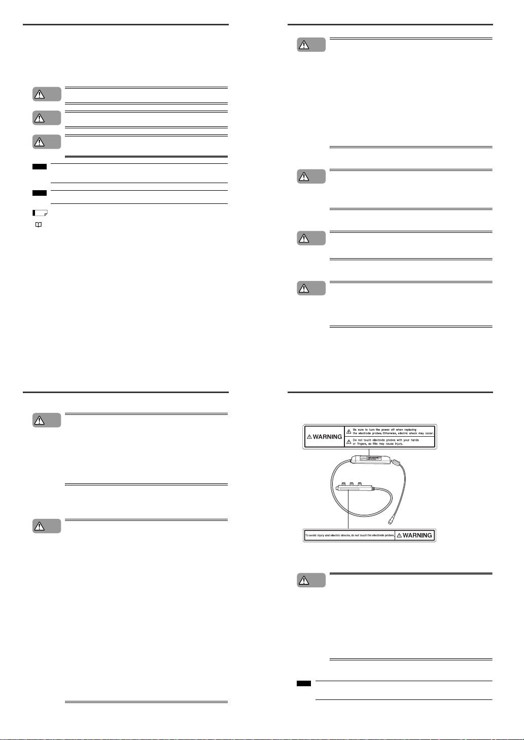
■ SJ-M Series Warning label
A WARNING label is affixed on the SJ-M Series to ensure safety. Read the description on this
WARNING label to ensure correct use of the SJ-M Series.
■ Installation Precautions
Avoid installing the SJ-M Series in the following locations as this may cause
accidents.
• Locations directly subject to vibration and shock
• Locations subject to ambient temperature outside of the 0°C to +40°C range
• Locations subject to ambient humidity outside of the 35 to 65%RH range
(condensation not allowed)
• Locations subject to sudden changes in temperature
• Locations subject directly to blasts from air conditioners
• Locations subject to volatile or flammable substance, solvents or corrosive
gases
• Locations subject to large amounts of dirt, and dust, salt, iron and oil smoke
• Locations that may be splashed with water, oil or chemical mist
• Locations where strong magnetic and electrical fields are generated
■ About Warm-up
After turning the SJ-M Series ON, leave it for about 20 minutes to allow the ion
balance to stabilize.
WARNING labels in Japanese, German, French, Italian and Chinese (Simplified) are provided.
Use them as necessary.
CAUTION
Note
1
Page 3
■ Other Precautions
•
Be sure to read the WARNINGS and CAUTIONS described in each of the
items in this Instruction Manual.
•
This Static Eliminator has a built-in EEPROM. Do not turn the Static
Eliminator OFF during the setup.
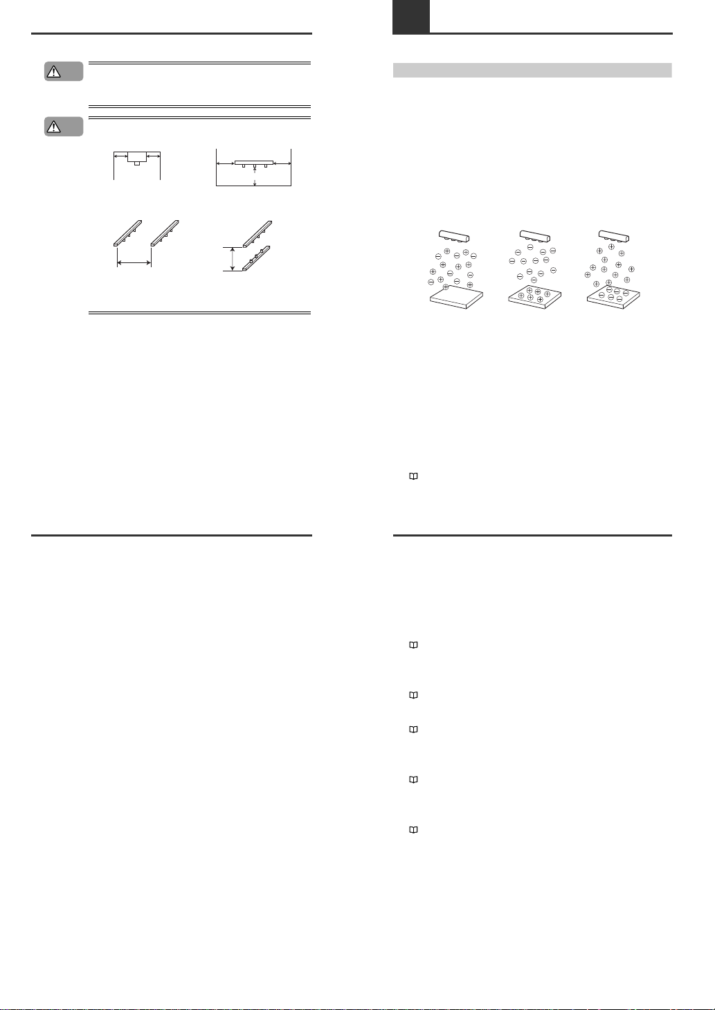
Refer to the following illustration to install the SJ-M300.
●Provide enough space between the static elimination bar and surrounding
walls as shown in the figures below.
●If a number of SJ-M300 units are used in combination, make a proper
distance between adjacent static elimination bars.
• Do not install the Static Elimination Head at locations where moving parts of
other equipment and machinery may place stress on the cable.
CAUTION
CAUTION
20mm
min.
20mm
min.
20mm min.
30mm
min.
30mm
min.
Side-to-side installation
300mm
min.
Face-to-face installation
100mm
min.
Precautions on Regulations and Standards
■ CE Marking
Keyence Corporation has confirmed that this product complies with the essential requirements of the
applicable EC Directive, based on the following specifications.
Be sure to consider the following specifications when using this product in the Member State of
European Union.
● EMC Directive (2004/108/EC)
• Applicable standard EMI: 61326-1(evaluated according to EN55011 Group 1, Class A)
EMS: 61326-1
• Be sure to provide a ground when installing the SJ-M Series.
• The length of cable (power lead and I/O leads) must be less than or equal to 30 m.
Remarks:
These specifications do not give any guarantee that the end-product with this product incorporated
complies with the essential requirements of EMC Directive. The manufacturer of the end-product is
solely responsible for the compliance on the end-product itself according to EMC Directive.
● Low-Voltage Directive (2006/95/EC)
• Applicable Standard : EN61010-1
• Overvoltage category I
• Use this product under pollution degree 2.
• Use the power supply for the SJ-M Series, that satisfies the requirements of the Limited Power
Source specifications stipulated in EN60950-1 and certified by European third-party certification
organization, or a Keyence Corporation AC adapter (SJ-U2). The specifications of the AC adapter
(SJ-U2) are as follows.
When connecting to an SJ-U2, be sure to use a power cable compliant with European standards.
Applicable standard: EN60950-1
Overvoltage category II
Pollution degree 2
• Be sure to provide a ground when installing the SJ-M Series.
1-1 Features of the SJ-M Series
This section describes an outline of the functions, the features of the SJ-M Series.
Outline of the SJ-M Series
■ Pulse AC method
The SJ-M Series uses a pulse AC method that generates + and – charged air ions from a single
electrode probe. This system ensures a maximum ion level per unit time, which in turn high-speed static
elimination. The SJ-M Series also automatically controls the level of + and – ions generated matched to
the charged state of the target object. This enables high-speed and high-precision static elimination
suited to installation conditions.
■ I.C.C. (Ion Current Control) method
This control method calculates the charged level of the target object by sensing the state of ion current
that arises due to the potential difference between the electrode on the Static Elimination Head and
GND. Optimum static elimination matched to the state of the target object can be performed by rapidly
supplying the optimum ions suited to the polarity and charged level of the target object.
■ Versatile frequency settings
A variety of frequencies can be set for the SJ-R. This allows optimal static elimination according to the
distance and the strength of the electric charge of the target.
■ Ion monitor functions
●
Charge monitor
The integrated ion monitor allows you to learn how much the target object is charged by + or – ions.
This monitor also allows you to confirm at a glance how static elimination is being performed.
● Ion level monitor
The ion level currently being generated by the Static Elimination Head is monitored at all times so that
drops in the generated ion level can be diagnosed on the unit. The generated ion level is indicated by
LEDs and an alarm can be output when the generated ions fall below a certain level. This allows you to
monitor the influence of a dirty electrode probe in advance.
"Ion Monitor Functions" (page 8)
Target without
static charge
Eliminates electricity
from positively
charged target
Eliminates electricity
from negatively
charged target
Target: 0V Target: Positively charged Target: Negatively charged
1-1
Features of the SJ-M Series
■ Alarm output functions
●
Alarm output functions
An indicator blinks and an alarm signal is output, for example, when internal circuits are damaged or
abnormal discharging occurs. When an alarm signal is output, generation of ions is forcibly stopped.
● Ion level alarm output function
An indicator lights and an alarm signal is output when the level of generated ions drops due to a dirty
electrode probe, for example.
● Condition alarm output function
An indicator lights and an alarm signal is output when static elimination performance is impaired.
"Alarm Output Functions" (page 8)
■ Abnormal discharge detection function
Abnormal discharge caused by condensation on the electrode probe tip or adhesion of debris is
detected. When abnormal discharge is detected, ion generation is forcibly stopped to prevent trouble at
an early stage.
"Abnormal Discharge Detection Function" (page 8)
■ Ion balance adjustment function
The ion balance zero point can be fine-adjusted.
"Ion Balance Adjustment Function" (page 7)
■ Static elimination stop function
Static elimination only can be turned ON/OFF with the device still powered. This is achieved by shorting
the 0V terminal with the static elimination stop input terminal on the Controller Unit (I/O terminal
section) or by holding down the two ion balance adjustment keys simultaneously for about one second.
"Static Elimination Stop Function" (page 8)
■ Air purge function
Dirt can be prevented from sticking to the electrode probe on the SJ-M030 by attaching a joint to the air
duct of the Static Elimination Bar and supplying clean dry air from the air compressor. This also extends
the static elimination range.
"Air Purge Function" (page 9)
2
Page 4
1-2
Checking the Contents of the Package
The package contains the following components and accessories. Before you start using the SJ-M
Series, make sure that the package contains everything that it is supposed to contain. A Replacement
Electrode Unit and other accessories are available as options.
"Appendices - List of Options" (page 13)
Package Contents
Options
WARNING labels (Japanese, German, French, Italian and Chinese
(Simplified)) *
* Use as necessary.
CompactSpot-typeStatic Eliminator
Instruction Manual
SJ-M Series
Before using this Compact Static Eliminator, be sure to
thoroughly read this Instruction Manual.
After you are finished with this Instruction Manual, be
sure to store it in a safe place for quick reference.
CompactSpot-typeStatic Eliminator
Instruction Manual
SJ-M
96M1533
Controller Unit (SJ-M300)Static Elimination Bar
Instruction Manual
SJ-M030/070 Series Mounting Fixture
1set
Flat-blade
screwdriver
Earth lead
AC Adapter SJ-U2
Extension cable SJ-C3
(3m cable, can be extended to 9m)
Tungsten electrode probe for SJ-M030/070 (set of 4 pieces) OP-42213
Silicon electrode probe for SJ-M030/070C (set of 4 pieces) OP-42214
Tungsten electrode probe for SJ-M030/070G (set of 4 pieces) OP-51644
Tungsten electrode probe for SJ-M030/070V (set of 4 pieces) OP-75352
Silicon electrode probe for SJ-M030/070VC (set of 4 pieces) OP-75353
*
For details of the AC cable, contact the
KEYENCE sales office in your district.
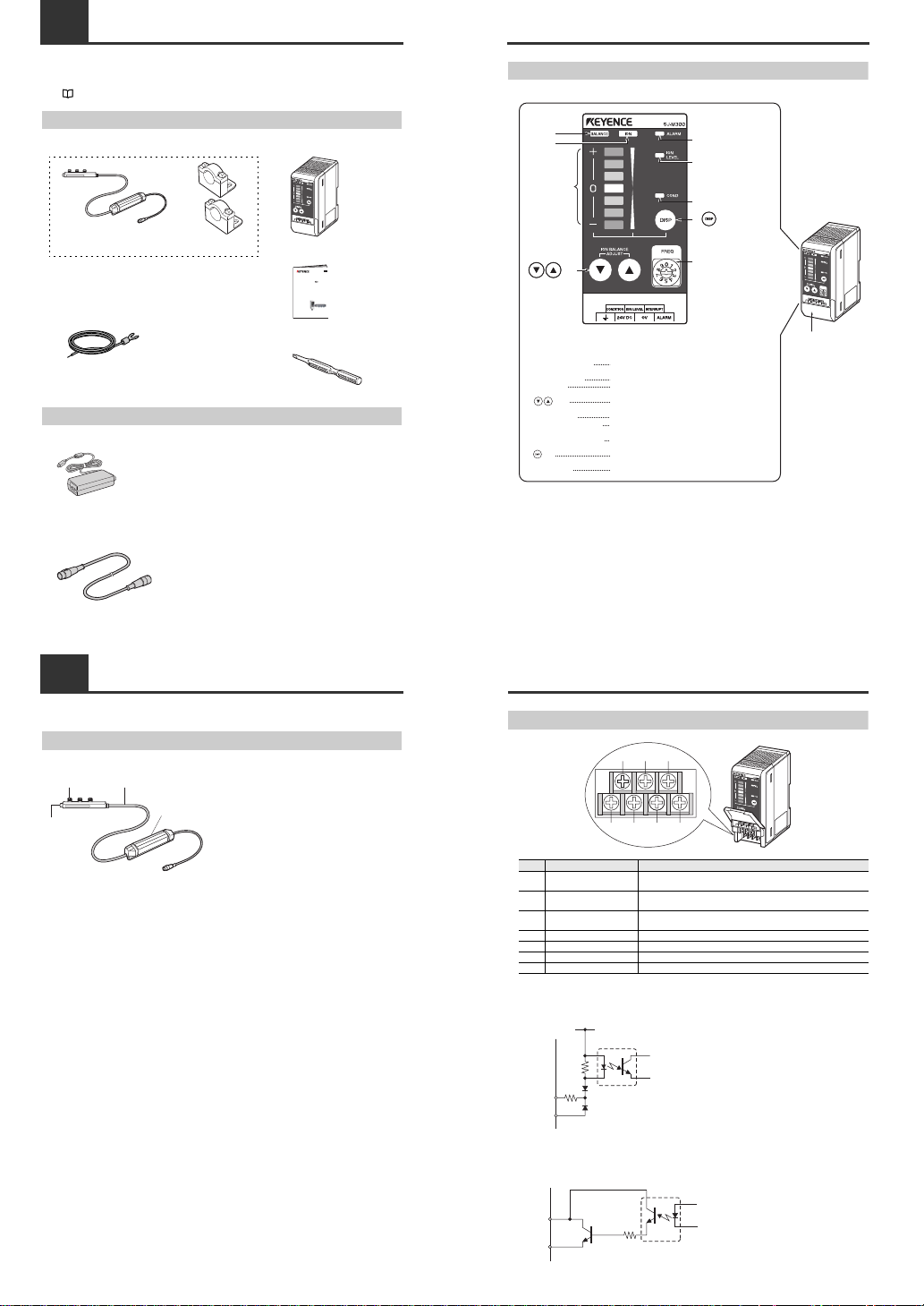
1-3 Names and Functions of Parts
This section describes the names and functions of parts on the SJ-M Series.
Static Elimination Bar
● SJ-M030/070 Series
(2)
(3)
(4)
(1)
(1) Electrode probe
Ion charge is emitted from the tip of this probe.
(2) Air duct
Supplies clean dry air.
(3) High-voltage cable
Ambient operating temperature: 0 to +40°C
Minimum bending radius 30 mm
(4) Drive unit
Manages body information of the Static
Elimination Bar or drives the Bar.
1-3
Names and Functions of Parts
Controller Unit (operation/display section)
Enlarged view of display section
Terminal plate cover
Lights when the charged level of the target object is
displayed.
Lights when the ion emission level is being displayed.
Indicates the charged level of the target object.
Also, indicates the ion emission level.
Used for adjusting the ion balance and for selecting setting
items.
Lights when an alarm occurs.
Lights when the ion emission level has fallen below the set
value due to dirt or wear of the electrode probe.
Lights when the charged level of the target object is high
and static cannot be completely eliminated.
Used for determining setting items and for switching the
display.
Used for switching the frequency.
Ion balance
indicator
Ion level
indicator
Ion monitor
keys
key
Alarm indicator
Ion level alarm indicator
Condition alarm indicator
Ion balance indicator
Ion level indicator
Ion monitor
keys
Alarm indicator
Ion level alarm indicator
Condition alarm indicator
key
Rotary switch
(1)
(2)
(3)
(4)
(5)
(6)
(7)
(8)
(1)
(2)
(3)
(4)
(5)
(6)
(7)
(8)
(9)
(9) Rotary switch
FREQ
1-3
Names and Functions of Parts
Controller Unit (I/O terminal section)
■ Input circuit diagram
■ Output circuit diagram
Number
Name Function
(1)
Condition alarm output
terminal
Outputs when static elimination performance is influenced by excessive
charge.
(2)
Ion level alarm output
terminal
Outputs when the ion emission level drops.
(3)
Static elimination stop input
terminal
Static elimination can be turned ON/OFF by shorting this terminal with
(6).
(4) Ground terminal Be sure to connect a Class D earth (maximum resistance of 100 Ohms).
(5) DC power terminal 24 VDC ±10%
(6) 0V terminal 0V for power and 0V for I/O
(7) Alarm output terminal Outputs when an alarm occurs.
(1)
(4) (5) (6) (7)
(2) (3)
+24V
3kΩ
INPUT( (3) )
0V( (6) )
Input a no-voltage contact (relay, etc.)
or NPN open collector to INPUT and 0V.
[ (3) (static elimination stop input)]
OUT
DC40V
100mA
0V( (6) )
Open collector output
[ (2) (ion level alarm output), (1) (condition alarm output), (7) (alarm output)]
3
Page 5
2-1 Before Installation
This section describes the static elimination performance of the SJ-M100/200 Series.
Before you install the SJ-M100/200 Series, fully calculate the distance between the Static Elimination
Head up to the target object and the time required for static elimination.
About Static Elimination Performance
■ Static elimination speed and operating distance
The SJ-R Series offers a variety of frequency settings to enable flexible static elimination according to
the location and application.
See "Frequency setting" (page 6).
The following graphs show typical examples of the relationship of static elimination speed, operating
distance, and frequency settings for the SJ-R Series. Use the graphs to select the appropriate static
elimination setting.
■
Operation time vs. operating distance
Static elmination
speed
Location
Operating
distance(mm)
Recommended
frequency (Hz)
High-speed
Low-speed
Production lines of films or sheets
(Short distance)
50–300 50, 30
Clean bench (Middle distance) 300–1000 10, 8, 5
On ceiling of clean room (Long distance) 1000–2000 3, 1
Model: SJ-M030/030C
Measurement conditions:
The time required to eliminate the static charge of the
target from ±3000 V to ±300 V is measured.
The 150 x 150 mm plate monitor (20pF) is used.
Measurement conditions:
The time required to eliminate the static charge of the
target from ±5000 V to ±500 V is measured.
The 150 x 150 mm plate monitor (20pF) is used.
Under the downward air flow of 0.3 m/sec.
Model: SJ-M070/070C
50Hz
30Hz
25
20
15
10
5
30
Charged level (V)
Time (secs)
0
0 50 100 150 200 250 300
8Hz
5Hz
1Hz
50
60
40
30
20
10
0
0
400
600 800
1000
1200
1400
1600200
Charged level (V)
Time (secs)
0
2
4
6
8
10
12
14
16
18
20
0 50 100 150 200 250 300
Operating distance (mm)
Operating time (sec.)
50Hz
30Hz
0
5
10
15
20
25
30
35
0 200 400 600 800 1000 1200 1400 1600
Operating distance (mm)
Operating time (sec.)
8Hz
5Hz
1Hz
2-1
Before Installation
Measurement conditions:
The time required to eliminate the static charge of the
target from ±3000 V to ±300 V is measured.
The 150 x 150 mm plate monitor (20pF) is used.
The downward air flow of 0 m/sec
3 NL/min (1 electrode) air purge
Measurement conditions:
The time required to eliminate the static charge of the
target from ±5000 V to ±500 V is measured.
The 150 x 150 mm plate monitor (20pF) is used.
Under the downward air flow of 0.3 m/sec.
3 NL/min (1 electrode) air purge
Model: SJ-M030G
Model: SJ-M070G
50Hz
30Hz
4
3
2
0
0150 100 150 200 250 300
3.5
2.5
1.5
0.5
Operating time (sec.)
Operating distance (mm)
8Hz
5Hz
1Hz
25
30
20
15
10
5
0
0
400
600 800
1000
1200
1400
1600200
Charged level (V)
Time (secs)
0
0.5
1
1.5
2
2.5
3
3.5
4
0 50 100 150 200 250 300
Operating distance (mm)
Operating time (sec.)
50Hz
30Hz
0
2
4
6
8
10
12
14
16
0 200 400 600 800 1000 1200 1400 1600
Operating distance (mm)
Operating time (sec.)
8Hz
5Hz
1Hz
Measurement conditions:
The time required to eliminate the static charge of the
target from ±3000 V to ±300 V is measured.
The 150 x 150 mm plate monitor (20pF) is used.
The downward air flow of 0 m/sec
1 NL/min (1 electrode) air purge
Measurement conditions:
The time required to eliminate the static charge of the
target from ±5000 V to ±500 V is measured.
The 150 x 150 mm plate monitor (20pF) is used.
Under the downward air flow of 0.3 m/sec.
1 NL/min (1 electrode) air purge
Model: SJ-M030V/030VC
Model: SJ-M070V/070VC
50Hz
30Hz
20
18
16
14
12
10
8
6
4
2
0
0 50 100 150
200
250
300
Charged level (V)
Time (secs)
8Hz
5Hz
1Hz
50
60
40
30
20
10
0
0
400
600 800
1000
1200
1400
1600200
Charged level (V)
Time (secs)
0
2
4
6
8
10
12
14
16
18
20
0 50 100 150 200 250 300
Operating distance (mm)
Operating time (sec.)
50Hz
30Hz
0
10
20
30
40
50
60
0 200 400 600 800 1000 1200 1400 1600
Operating distance (mm)
Operating time (sec.)
8Hz
5Hz
1Hz
2-1
Before Installation
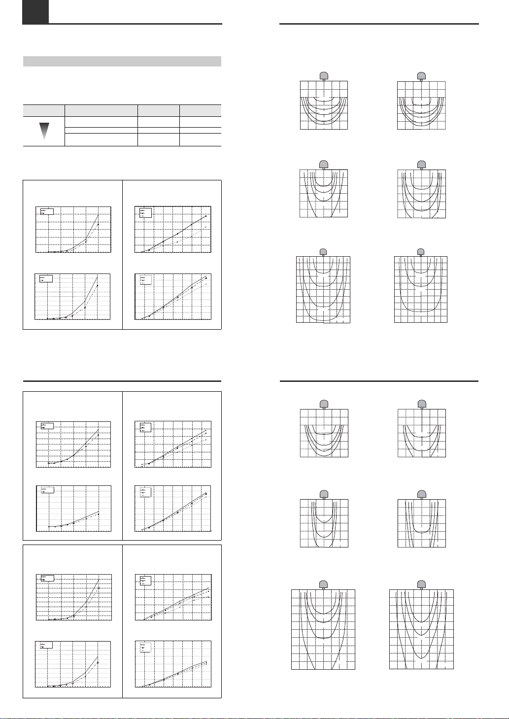
■ Operating area and operation time
The following graphs show typical examples of the relationship between the time required to eliminate
the target's static charge and the operating distance from the target to the static elimination bar.
Use the graphs to select the appropriate static elimination setting.
Model: SJ-M030/030C
At the time of frequency 50 Hz
Model: SJ-M070/070C
At the time of frequency 50 Hz
Measurement conditions:
The time required to eliminate the static charge of the
target from ±3000 V to ±300 V is measured.
The downward air flow: 0 m/sec
The air purge: 0 NL/min
Measurement conditions:
The time required to eliminate the static charge of the
target from ±3000 V to ±300 V is measured.
The downward air flow: 0 m/sec
The air purge: 0 NL/min
At the time of frequency 8 Hz At the time of frequency 8 Hz
Measurement conditions:
The time required to eliminate the static charge of the
target from ±5000 V to ±500 V is measured.
The downward air flow: 0.3 m/sec
The air purge: 0 NL/min
Measurement conditions:
The time required to eliminate the static charge of the
target from ±5000 V to ±500 V is measured.
The downward air flow: 0.3 m/sec
The air purge: 0 NL/min
At the time of frequency 1 Hz At the time of frequency 1 Hz
Measurement conditions:
The time required to eliminate the static charge of the
target from ±5000 V to ±500 V is measured.
The downward air flow: 0.3 m/sec
The air purge: 0 NL/min
Measurement conditions:
The time required to eliminate the static charge of the
target from ±5000 V to ±500 V is measured.
The downward air flow: 0.3 m/sec
The air purge: 0 NL/min
50100150
50
100
150mm
50 100 150mm
0.4sec
0.6sec
0.8sec
1.2sec
1.5sec
50100150
50
100
150mm
50 100
150mm
0.4sec
0.6sec
0.8sec
1.2sec
1.5sec
150300450
300
600
900mm
150 300
450mm
5sec
10sec
15sec
30sec
150300450
300
600
900mm
150 300
450mm
5sec
10sec
15sec
20sec
300450600 150 450300150 600mm
300
600
900
1200
1500mm
4sec
20sec
30sec
300450600 150 4503001 50 600mm
300
600
900
1200
1500mm
4sec
10sec
20sec
2-1
Before Installation
Model: SJ-M030G
At the time of frequency 50 Hz
Model: SJ-M070G
At the time of frequency 50 Hz
Measurement conditions:
The time required to eliminate the static charge of the
target from ±3000 V to ±300 V is measured.
The downward air flow: 0 m/sec
The air purge: 3 NL/min (1 electrode)
Measurement conditions:
The time required to eliminate the static charge of the
target from ±3000 V to ±300 V is measured.
The downward air flow: 0 m/sec
The air purge: 3 NL/min (1 electrode)
At the time of frequency 8 Hz At the time of frequency 8 Hz
Measurement conditions:
The time required to eliminate the static charge of the
target from ±5000 V to ±500 V is measured.
The downward air flow: 0.3 m/sec
The air purge: 3 NL/min (1 electrode)
Measurement conditions:
The time required to eliminate the static charge of the
target from ±5000 V to ±500 V is measured.
The downward air flow: 0.3 m/sec
The air purge: 3 NL/min (1 electrode)
At the time of frequency 1 Hz At the time of frequency 1 Hz
Measurement conditions:
The time required to eliminate the static charge of the
target from ±5000 V to ±500 V is measured.
The downward air flow: 0.3 m/sec
The air purge: 3 NL/min (1 electrode)
Measurement conditions:
The time required to eliminate the static charge of the
target from ±5000 V to ±500 V is measured.
The downward air flow: 0.3 m/sec
The air purge: 3 NL/min (1 electrode)
50100150
50
100
150mm
50 100 150mm
0.4sec
0.8sec
0.6sec
1.0sec
50100150
50
100
150mm
50 100 150mm
0.4sec
0.6sec
0.8sec
50100150
50
100
150mm
50 100 150mm
5sec
15sec
10sec
50100150
50
100
150mm
50 100 150mm
5sec
15sec
10sec
300450600 150 450300150 600mm
300
600
900
1200
1500mm
20sec
10sec
6sec
4sec
300450600 150 450300150 600mm
300
600
900
1200
1500mm
4sec
10sec
20sec
6sec
4
Page 6

2-1
Before Installation
Model: SJ-M030V/030VC
At the time of frequency 50 Hz
Model: SJ-M070V/070VC
At the time of frequency 50 Hz
Measurement conditions:
The time required to eliminate the static charge of the
target from ±3000 V to ±300 V is measured.
The downward air flow: 0 m/sec
The air purge: 1 NL/min (1 electrode)
Measurement conditions:
The time required to eliminate the static charge of the
target from ±3000 V to ±300 V is measured.
The downward air flow: 0 m/sec
The air purge: 1 NL/min (1 electrode)
At the time of frequency 8 Hz At the time of frequency 8 Hz
Measurement conditions:
The time required to eliminate the static charge of the
target from ±5000 V to ±500 V is measured.
The downward air flow: 0.3 m/sec
The air purge: 1 NL/min (1 electrode)
Measurement conditions:
The time required to eliminate the static charge of the
target from ±5000 V to ±500 V is measured.
The downward air flow: 0.3 m/sec
The air purge: 1 NL/min (1 electrode)
At the time of frequency 1 Hz At the time of frequency 1 Hz
Measurement conditions:
The time required to eliminate the static charge of the
target from ±5000 V to ±500 V is measured.
The downward air flow: 0.3 m/sec
The air purge: 1 NL/min (1 electrode)
Measurement conditions:
The time required to eliminate the static charge of the
target from ±5000 V to ±500 V is measured.
The downward air flow: 0.3 m/sec
The air purge: 1 NL/min (1 electrode)
50100150
50
100
150mm
50 100 150mm
0.4sec
0.6sec
1.0sec
1.5sec
2.0sec
50100150
50
100
150mm
50 100 150mm
0.4sec
0.6sec
1.0sec
1.5sec
2.0sec
150300450
300
600
900mm
150 300 450mm
10sec
15sec
30sec
5sec
150300450
300
600
900mm
150 300 450mm
10sec
15sec
30sec
5sec
300450600 150 450300150 600mm
300
600
900
1200
1500mm
20sec
30sec
10sec
6sec
4sec
300450600 150 450300150 600mm
300
600
900
1200
1500mm
20sec
30sec
10sec
4sec
2-1
Before Installation
■ Proper static elimination
To e ns ure proper static elimination, consider the following points.
If the target is in contact with metallic objects (grounding
conductor), the static charge of the target is not completely
eliminated.
Install the SJ-M Series in a location in which the target is not in
contact with any metallic objects (such as a grounding conductor).
If the film or sheet is an electrical insulator, only the static
electricity on the surface exposed to the static elimination bar
is eliminated.
To eliminate the static electricity on both surfaces, use another
SJ-M unit on the other side.
Precautions for installation
■ Locations
Refer to the following illustration to install the SJ-M Series.
• Provide enough space between the static elimination bar and surrounding
walls as shown in the figures below.
•
When mounting the SJ-M Series, use the provided mounting bracket,
otherwise an accident or malfunction may result.
Target (film or sheet)
Metal roller
NG
OK
OK
• Install the static elimination bar in a
location that allow easy maintenance
access (to replace or clean parts).
Note
CAUTION
20mm
min.
20mm
min.
20mm min.
30mm
min.
30mm
min.
2-1
Before Installation
■ Interference
The Static Elimination Head may not function properly if there is a conductor (earthed body) located
nearby or if two or more units are used close to each other. In such an installation, refer to the figure
below and maintain the indicated distance between the conductor (earthed body). If a conductor (earthed
body) is located inside the distances indicated below, adjust using the ion balance manual setup.
"Ion Balance Adjustment Function" (page 7)
If two SJ-R units are used, refer to the following illustration and separate the static elimination bars
properly.
The interference distance between the conductive object and the static elimination bar and that
between the static elimination bars located in parallel are specified, on condition that the target is
located at the following distances under a down flow of 0.3 m/s.
The interference distance between the static elimination bars located face to face is specified under no
wind flow.
Frequency (Hz) Operating distance (mm)
50 50
30 150
10 300
8 600
5 900
3 1200
1 1500
20mm
min.
20mm
min.
20mm min.
30mm
min.
30mm
min.
Side-to-side installation
300mm
min.
Face-to-face installation
100mm
min.
2-2 Connection and Installation
This section describes how to connect and install the Static Elimination Head and Controller Unit.
Installing the SJ-M Series
■ Installing the Static Elimination Bar
●
Install the static elimination bar in the desired location.
Adjust the angle of the mounting brackets so that the
static elimination bar is properly secured at the desired
angle. Tap M4 screw holes at the appropriate location
and secure the static elimination bar using M4 screws.
• Do not allow any objects to contact the static elimination bar after
installation, as this may lead to product breakdown.
• When installing the SJ-M Series, observe the minimum bending radius of all
provided cables. Also, do not install the SJ-M Series with the cables
deformed by staples or other objects. Doing so might cause the SJ-M Series
to malfunction.
● When the mounting fixture is used:
When installing the drive unit, prepare tapped
mounting holes, and install the drive unit at a tightening
torque of 1 Nm or less (M4 screws: 1 Nm or less).
The M3 screws and bundling band for fastening the
mounting fixture must be prepared separately.
Make a space of 30 mm or more around the drive unit. Otherwise, the unit may
be damaged.
■ Installing the Controller unit
Mount the Controller Unit on the DIN rail.
M4 screws
M4 taps
In case of the side mounting, use the
ion balance adjustment function to
adjust the ion balance again.
( page 7)
Note
CAUTION
M4 Tap
CAUTION
FREQ
5
Page 7

2-2
Connection and Installation
Connecting Cables
When you have finished installing the Static Elimination Bar, connect the earth lead, Static Elimination
Head connector cable and power supply.
■ Connecting the earth lead
Open the terminal plate cover on the Controller
Unit, and connect the earth lead to the GND
connection terminal.
Be sure to connect a Class D earth (maximum
resistance of 100 Ohms).
To prevent electric shock and to ensure accurate static elimination, be sure to
connect a Class D earth (maximum resistance of 100 Ohms).
■ Connecting the cable
Connect the Static Elimination Bar
connector cable to the Controller Unit.
Connect this cable with the power
turned OFF.
When installing the Controller Unit
away from the Static Elimination Bar,
use the optional extension cable (SJC3).
■ Connecting the power supply
Connect the power supply according to either
of the following methods.
24 VDC power supply
Connect a 24 VDC output power supply
having sufficient power capacity margin to the
power terminals (terminals (5) and (6))
"Controller Unit (I/O terminal section)" (page
3)
Be sure to connect
a Class D earth
(maximum resistance
of 100 Ohms).
WARNING
Match and connect
the end of the connector
cable to the inlet on the
Controller Unit.
To 24 VDC
power supply
To 24 VDC
power supply
2-2
Connection and Installation
AC adapter (SJ-U2)
Connect the AC adapter to the connector on the side of
the Controller Unit.
The AC adapter is available as an option.
3-1 SJ-M Series Operations
This section describes operation of the SJ-M Series.
Setup Flow
The setup flow for setting up the SJ-M Series is as follows.
■ When the SJ-M Series is turned ON for the first time
■ Moving between modes
Modes on the SJ-M series change as follows.
The unit starts up in the Run mode after the power is turned ON or after static elimination is
stopped.
1 Frequency setting
2 Function setting
Set and change
functions
in each mode.
<Run mode> <Select mode>
<Ion Balance Manual Adjustment mode>
<Setup mode>
One lit Blink alternately Blink alternately fast
Press for
a short time.
"BALANCE" lit
Hold down for
at least 1 second.
Hold down for
at least 1 second.
Hold down and
simultaneously
for at least 1 second.
Tip
3-1
SJ-M Series Operations
Frequency setting
A frequency is set with the FREQ switch in the SJ-M Series.
For frequency settings in detail, see "About Static Elimination Performance" (page 4).
When the frequency changes, the ion balance adjustment value (see page 7) is
initialized. Adjust the ion balance again.
FREQ switch setting number Frequency
0 50Hz
1 30Hz
2 10Hz
38Hz
45Hz
53Hz
61Hz
7 Continuous positive ion generation
8 Continuous negative ion generation
9
Output terminal test mode. All output of alarm, ion level alarm,
condition alarm is ON. Static elimination stops.
FREQ
0
1
2
3
4
5
6
7
8
9
The illustration shows that the
FREQ switch is set to 0.
Note
6
Page 8

3-1
SJ-M Series Operations
Run Mode
Regular static elimination operation is performed in the Run mode.
The following functions are available in the Run mode.
●Ion monitor functions
"Ion Monitor Functions" (page 8)
●Alarm output functions
"Alarm Output Functions" (page 8)
●Confirmation of ion balance adjustment values
Select Mode
In this mode, select the setting items to change in the Setup mode
Setup Mode
In this mode, change the settings of the items selected in the Select mode.
A
B
C
D
Blink alternately
1
424
3
Operations in the Select mode
Press for a short time:
Enters the Setup mode for the currently selected item.
Hold down for at least 1 second:
Exits the Select mode, and returns to the Run mode.
: Move the cursor up and down.
On the ion monitor, the currently selected items are lit (green), and the items
whose defaults have been changed are lit (red).
Items that satisfy both of these conditions blink red and green alternately.
The following describes each of the items in the Select mode:
:
Ion level alarm, sensitivity setting
:
Condition alarm, sensitivity setting
:I.C.C. ON/OFF
:
Initialization of settings
1
424
3
Blink alternately fast
Operations in the Setup mode
:Applies the setting at the selected conditions.
:Move the cursor up and down.
The following describes each of the items in the Setup mode:
424
3
3-1
SJ-M Series Operations
■ Ion level alarm sensitivity setup
Sets the sensitivity at which the ion level alarm is output.
(1) High sensitivity (red): Alarms are easily output.
(2) Medium sensitivity (orange):
(3) Low sensitivity (green): Alarms are not easily output.
(4) No sensitivity (red): Alarms are easily output.
Default is “Low sensitivity.”
"Ion level alarm output function (ION LEVEL)" (page 8)
■ Condition alarm sensitivity setup
Sets the sensitivity at which the condition alarm is output.
(1) High sensitivity (red): Alarms are easily output.
(2) Medium sensitivity (orange):
(3) Low sensitivity (green): Alarms are not easily output.
(4) No sensitivity (red): Alarms are easily output.
Default is “Low sensitivity.”
"Condition alarm output function (COND)" (page 8)
①
②
③
④
Blin
k
Tip
①
②
③
④
Blin
k
Tip
3-1
SJ-M Series Operations
■ I. C. C. ON/OFF Setting
Advance to the
I.C.C. ON/OFF
setting from the Select mode in
page 7, and select either of the followings.
(1)
I.C.C. O N
(green) (Default)
(2)
I.C.C. O FF
(red)
■ Initialization of settings
Returns settings to their defaults.
(1) Press , or for a short time:
Returns to the Select mode without initializing the settings.
(2) Hold down for at least one second:
Initializes the settings and returns to the Select mode.
When settings are initialized, the ion monitor indication moves
towards both ends of the display.
①
②
Blin
k
Blin
k
When the I.C.C. OFF is selected, the ion level
alarm will not be output correctly. Ion level
monitor indication is not available, either.
Important
①
Blin
k
Tip
3-1
SJ-M Series Operations
Ion Balance Manual Adjustment Mode
In this mode, you can adjust the zero point, the point for reference for the I.C.C. function.
Ion Balance Adjustment Function
The SJ-M Series automatically senses the charged level of the target body by the I.C.C. function to
automatically control the generated amount (balance) of plus and minus ions.
The zero point, the point for reference for the I.C.C. function, is adjusted before the SJ-M Series is
shipped from the factory. However, in some environments, the zero point sometimes drifts. If this
reference zero point drifts, adequate static elimination cannot be maintained. For this reason, you need
to adjust the zero point again by “Ion Balance Adjustment Function”.
Do not turn the power OFF while the ion balance is being adjusted (about 1
minute).
■ Setting the ion balance
1 Hold down for at least one second to enter the ion
balance manual adjustment mode.
The ion balance indicator blinks.
2 Set the ion balance using .
The LED on the ion monitor corresponding to the set value lights.
CAUTION
Key Function
Key Shifts the zero point in the + direction.
Key Shifts the zero point in the – direction.
Hold down for a
t
least 1 second.
1
7
Page 9

3-1
SJ-M Series Operations
3 Press to end ion balance setup.
Holding down for about
one second when setting the
ion balance clears the preset
ion balance zero point and
returns the ion balance to its
default setting.
Blink fast
The mode changes to the Run mode.
After you have finished setting up the ion balance, the ion
balance indicator will blink fast fo r about max. three minites,
indicating that the ion balance setup is being written to memory.
After you have finished setting up the ion
balance, do not change the ambient
environment for about 1 minute. If you do, the
zero point sometimes cannot be set accurately.
Note
Note
During this operation,
the ion monitor indication
moves towards both ends
of the display.
3-2 Ion Monitor Functions
This section describes the ion monitor functions of the SJ-M Series.
Ion monitor functions are enabled in the Run mode.
Ion Monitor Functions
The charged level of the target object and the level of ions generated from the static elimination head
are indicated on the ion monitor.
The ion monitor indication can be switched by .
■ Charge monitor
This monitor indicates the charged and decharged
states of the target object.
The indication of this monitor fluctuates towards the
+ and – sides according to the charged level. The
further the indication is away from the center LED,
the larger the charged level. When static elimination
is completed, the indication returns to the center
LED so that you can easily tell how static
elimination is progressing.
The ion balance indicator lights when the charge
monitor is operating.
■ Ion level monitor
This monitor indicates the level of ions being
generated by the Static Elimination Head.
The level of plus ions being generated is indicated
on the upper side, while the level of minus ions is
indicated on the lower side. The further the
indication is away from the center LED, the larger
the level of ions. In a state where ions are being
sufficiently generated, both ends of this monitor light
(green).
The ion balance indicator lights when the ion level
monitor is operating.
Ion level monitor indication is not available when I.C.C. is OFF.
When I.C.C. is OFF, the ion balance indicator and ion level indicator light.
Red
Orange
Orange
Green
Orange
Orange
Red
Green
Green
Orange
Red
Orange
Green
Green
Max.
+ ion
Min.
Min.
- ion
Max.
Note
3-3 Alarm Output Functions
This section describes the alarm output functions of the SJ-M Series.
Alarm Output Functions
■ Alarm output function (ALARM)
The alarm indicator blinks (red) and an alarm signal
(control output (N.C.)) is output, for example, when
internal circuits are damaged or abnormal discharging
occurs. When an alarm signal is output, static
elimination is forcibly stopped.
Alarm output turns ON even in a static elimination
stopped state (including forced static elimination stop).
■ Ion level alarm output function (ION LEVEL)
The ion level alarm indicator lights and an alarm signal
(control output (N.O.)) is output when the level of
generated ions drops due to a dirty or worn electrode
probe, for example. When an alarm signal is output,
static elimination is not stopped.
Alarm output can be adjusted in three stages
according to the level of ions generated.
The default setting for the ion level alarm sensitivity
setting is Low.
The ion level alarm serves as a guideline for learning
when to perform maintenance on the electrode probe.
As static elimination is continued, be sure to turn the
power OFF before starting maintenance on the
electrode probe.
The ion level alarm output function is enabled in the
Run mode.
"Ion level alarm sensitivity setup" (page 7)
■ Condition alarm output function (COND)
The condition alarm output indicator lights and an
alarm signal (control output (N.O.)) is output when
static elimination performance is influenced by an
excessive charge on the target object. When an alarm
signal is output, static elimination is not stopped.
Alarm output can be adjusted in three stages
according to the installation environment. The default
setting for the condition alarm sensitivity setting is
Low.
The ion level alarm output function is enabled in the
Run mode.
"Condition alarm sensitivity setup" (page 7)
3-4 Other Functions
This section describes the abnormal discharge detection and static elimination stop functions of the SJM Series.
Abnormal Discharge Detection Function
To prevent trouble, the generation of ions is stopped when abnormal discharging caused by
condensation on the electrode probe tips or adhesion of debris, for example, is detected. At this time,
the alarm indicator and ion monitor blink to inform you that an abnormality has occurred. For details of
the indicated state on the Controller Unit (operation/display section), see "During an alarm (level 2)"
( page 13).
Static Elimination Stop Function
Static elimination only can be turned OFF in a powered ON state by two methods: by shorting the static
elimination stop input and 0V terminals on the Controller Unit (I/O terminal section), or by holding down
on the Controller Unit (operation/display section) simultaneously for about one second.
When static elimination stop input has been performed on the Controller Unit (operation/display
section), this state can be canceled by holding down simultaneously for about one second.
For details on indication states on the Controller Unit (operation/display section) when static elimination
stop input is canceled, see "Static elimination stop input (operation/display section)" ( page 13).
■ Static elimination stop input
Static elimination is stopped by either of the following methods.
By operation on the Controller Unit (I/O terminal section):
Short the static elimination stop input and 0V
terminals to stop static elimination.
The center LED of the ion monitor blinks (red).
"Controller Unit (I/O terminal section)" (p age
3)
To 24 VDC
power supply
To 24 VDC
power supply
8
Page 10

3-4
Other Functions
By operation on the Controller Unit (operation/display section):
Hold down simultaneously for about one
second to stop static elimination.
The three center LEDs of the ion monitor blink
(red).
Air Purge Function
Supplying clean air through the air duct on both ends of the static elimination bar will prevent the dust
accumulation on the electrode probes (SJ-M0
*
0G/V type). The air purge widens the static elimination
area and increases the speed of static elimination as well.
* The air pressure indicates the pneumatic value at the route of the joint.
Use clean air or dry air of temperature –25°C, and of mesh size of about 0.01 μm.
When supplying air to the SJSJ-G, SJ-V/VC Series, you can use the active carbon filter to decrease
the dust accumulation on the electrode probes.
• Be sure to limit the air pressure to 0.2 MPa. Exceeding this limit may cause
accidents or malfunction.
• Be sure to use clean air, dry air as the air for supplying to the Static
Elimination Head. Moisture or oil contained in the air or nitrogen may cause
discharge inside the Static Elimination Head, which may result in accidents
or malfunction.
■ Relationship between air pressure and air flow with different bar lengths
The relationship between air pressure and air flow varies depending on the length of the static
elimination bar.
Refer to the typical example below to select the appropriate air supply device (compressor) that will
supply sufficient air flow.
Hold down for
at least 1 second.
CAUTION
50
60
40
30
20
10
0
0
0.05
0.1 0.15 0.2
Charged level (V)
Time (secs)
SJ-M030
SJ-M030C
SJ-M030G
SJ-M030V
SJ-M030VC
0.05 0.1 0.15 0.2
SJ-M070/070C
SJ-M070G
SJ-M070V/070VC
120
100
80
60
40
20
0
0
Air pressure(MPa)
Air flow(Nl/min)
3-4
Other Functions
■ Relationship between operating time and operating distance with different
air pressure
The relationship between operating time and operating distance varies depending on the air pressure.
Refer to the typical example on the right to select the appropriate air pressure.
Model: SJ-M030/030C Model: SJ-M070/070C
Model: SJ-M030G Model: SJ-M070G
* 9NL/min is minimum air flow to get a CAB effect.
* 21NL/min is minimum air flow to get a CAB effect.
Model: SJ-M030V/030VC Model: SJ-M070V/070VC
* 3NL/min is minimum air flow to get a ACAB effect.
* 7NL/min is minimum air flow to get a ACAB effect.
0
1
2
3
4
5
6
7
8
9
10
0 50 100 150 200 250 300 350
Operating distance (mm)
Operating time (sec.)
No air
0.001MPa
0.01MPa
0.2MPa
0
1
2
3
4
5
6
7
8
9
10
0 50 100 150 200 250 300 350
Operating distance (mm)
Operating time (sec.)
No air
0.001MPa
0.01MPa
0.2MPa
0
1
2
3
4
5
6
7
8
9
10
0 50 100 150 200 250 300 350
Operating distance (mm)
Operating time (sec.)
No air
9NL/min
0.02MPa
0.2MPa
0
1
2
3
4
5
6
7
8
9
10
0 50 100 150 200 250 300 350
Operating distance (mm)
Operating time (sec.)
No air
21NL/min
0.02MPa
0.2MPa
0
1
2
3
4
5
6
7
8
9
10
0 50 100 150 200 250 300 350
Operating distance (mm)
Operating time (sec.)
3NL/min
0.05MPa
0.2MPa
0
1
2
3
4
5
6
7
8
9
10
0 50 100 150 200 250 300 350
Operating distance (mm)
Operating time (sec.)
7NL/min
0.05MPa
0.2MPa
3-4
Other Functions
■ Air supply method
As shown in the following figure, remove the screwwhich closes the air duct on the edge of the Static
Elimination Bar first. Then, attach a joint to the air duct and supply air.
• Be sure to limit the tightening torque to 2 N·m (20 kgf·cm) or less.
Otherwise, an accident or product breakdown may occur.
• Be sure to supply only clean, dry air. The use of improper air may cause an
accident or product breakdown.
● R ecommended joint
The recommended joint is the tube fitting(tube diamete: I6 mm, I8 mm) manufactured by Pisco Co..
CAUTION
Tube
Rc1/8
Joint for end unit
R1/8
Tube diameter I 6 mm : PC6-01SUS
Tube diameter I 8 mm : PC8-01SUS
3-4
Other Functions
I.C.C. Setting
The I.C.C. (Ion Current Control) can be turned on and off.
Turning off the I.C.C. allows the ion balance adjustment function to generate positive and negative ions
at a fixed ratio.
①
②
Either of them lit Blink alternately
Hold down
for at least
1 second
Hold down for at
least 1 second
simultaneously
<Run mode> <Select mode>
Change
Blink
Blink
Change the 4th LED from the top in the Select mode.
Press for a short time : advances to the Setup mode
of the selected item
Hold down for at least 1 second: exits the Select mode and
returns to the Run mode
: moves the cursor up and
down
On the ion monitor, the currently selected items are lit in green and the
items whose default have been changed are lit in red.
I.C.C. is set at ON by default setting.
Items that satisfy both of these conditions blink in red and green
alternately.
Advance to the I.C.C. ON/OFF setting from the Select mode in page 7,
and select either of the followings.
(1) I.C.C. ON (green) (Default)
(2) I.C.C. OFF (red)
When the I.C.C. OFF is selected, the ion level
alarm will not be output correctly. Ion level
monitor indication is not available, either. In the
Run mode, only the charge monitor is operating,
and the ion balance indicator and ion level
indicator light.
Important
9
Page 11

4-1 About Maintenance
Maintenance must be performed periodically to ensure that the static elimination performance of the
SJ-M Series is fully demonstrated. Maintenance personnel should thoroughly read the descriptions
under "Safety Precautions" ( page 1), and perform maintenance paying attention to the following
points.
About Maintenance
•
The SJ-M Series uses high voltage. Before starting maintenance, be sure to
turn the power OFF. Failure to do so might result in electric shock or
malfunction.
•
Do not directly touch the electrode probe. Take
care not to touch these probes even if the
power is turned OFF. Directly touching these
probes may cause personal injury.
When the SJ-M Series is used for a long period of time, the electrode probe becomes dirty due to the
adhesion of dust and dirt.
If the ion level alarm indicator lights, clean the electrode probe. If the electrode probe is used in a dirty
or dusty state, static elimination performance can no longer be fully demonstrated, resulting in
accidents or malfunction. We recommend periodically cleaning the electrode probe (as a guideline,
once every two weeks in a regular operating environment though this depends on the installation
conditions).
If cleaning the electrode probe does not improve the static elimination performance, or the ion level
alarm indicator frequently lights, replace the electrode probe.
If I.C.C. is set to OFF, the ion level alarm can not be judged correctly.
WARNING
Important
4-2
Performing Maintenance on the Electrode probe
When the SJ-M Series is used for a long period of time, the electrode probe becomes dirty due to the
adhesion of dust and dirt.
If the electrode probe is used in a dirty or dusty state, static elimination performance can no longer be
fully demonstrated, resulting in accidents or malfunction. Be sure to periodically perform maintenance
on the electrode probe.
Performing Maintenance on the Electrode probe
• At the time of maintenance, turn the SJ-M Series OFF.
• Do not directly touch the electrode probe with your hands. Doing so may
cause personal injury. Pay attention to this when performing maintenance
on the electrode probe.
■ How to clean the electrode probe
Clean the electrode probe gently with a cotton
wool bud moistened with alcohol.
■ How to replace the electrode probe
If the static elimination performance of an electrode probe does not recover or the ION LEVEL indicator
is lit frequently after cleaning, the life of the electrode probemay be expired. In that case, replace the
electrode probe.
Use the tungsten electrode probe as spares for SJ-G Series.
Replace all the remaining electrode probes along with the bad one, regardless of whether the
remaining electrode probes are still in serviseable condition or not.
WARNING
5-1 Timing Charts
This section provides timing charts for SJ-M Series.
■ Ion generation control timing chart
Indicator states when static elimination is OFF
Normal static elimination OFF
<during static elimination stop
input (terminal)>
The center LED of the ion monitor blinks (red).
■ Input response timing chart
Normally ON Normally OFF Normally ON Forced OFF Normally ON Normally OFF Normally ON
Static elimination
stop input (terminal)
ON
OFF
Static elimination
stop input (controller)
ON
OFF
Ion emission state
Unit indicator
Emitting
No emissions
Alarm output
ON
OFF
Forced OFF Forced OFFNormally ONNormally OFF
Max. 15 ms Max. 1 s
Static elimination
stop input (unit)
ON
OFF
Ion emission
state
Emitting
No emissions
Normal static elimination OFF <during
static elimination stop input (controller)>
The three center LEDs of the ion monitor
blink (red).
5-1
Timing Charts
■ Ion level alarm output timing chart
■ Condition alarm output timing chart
■ Alarm output timing chart
Power
ON
OFF
Static elimination
stop input (terminal)
ON
OFF
Static elimination
stop input (controller)
ON
OFF
Alarm indicator
Blinking
OFF
Alarm output (N.C.)
ON
OFF
Ion emission
Emitting
No emissions
Ion level indicator
Max. 15s
Blinking
OFF
Ion level alarm
output (N.O.)
ON
OFF
When the ion level al arm is output,
removing the cause of the alarm can
restore the normal state. One way of
restoring the normal state is to
perform maintenance on the electrode
probe.
For details on electrode probe
maintenance, see "Perfor
ming
Maintenance on the Electrode probe"
(page 10).
Power
ON
OFF
Alarm indicator
Blinking
OFF
Alarm output (N.C.)
ON
OFF
Ion emission
Emitting
No emissions
Condition indicator
Blinking
OFF
Condition alarm
output (N.O.)
ON
OFF
Max. 15s
Static elimination
stop input (terminal)
ON
OFF
Static elimination
stop input (controller)
ON
OFF
When the condition alarm is output,
removing the cause of the alarm can
restore the normal state. One way of
restoring the normal state is to
improve the installation environment.
Power
ON
OFF
Static elimination
stop input
ON
OFF
Alarm indicator
Blinking
OFF
Alarm output (N.C.)
ON
OFF
Ion emission
Emitting
No emissions
Max. 15s
When the alarm is output, the normal
state can be restored by perfor ming
one of the two available restore
methods depending on the cause of
alarm output.
For details on how to restore the
normal state, see “Durin
g an alarm
(levels 1, 2)” ( page 13).
10
Page 12

5-2 Specifications
This section provides the specifications of the SJ-M300 Series.
■ Static Elimination Bar/Controller Unit
*1: The following conditions were applied for measurement.
Please inquire for ion balance in operating distance 50mm (50 Hz) of a V,VC type separately.
*2: The effective length represents the operating area at an operating distance of 50 mm.
*3: The total length represents the length of the model with a mounting bracket attach.
■ AC adapter
* The power cable supplied with SJ-U2 is 125V rated power voltage.
Model
Static Elimination Bar
SJ-M030/030C/030G/
030V/030VC
SJ-M070/070C/070G/
070V/070VC
Controller Unit SJ-M300
Voltage application method Pulse AC
Applied voltage ±5.5 kV
Rated output voltage ±6 kV
Ion balance control method I.C.C. method
Ion balance *1 ±30 V
Air purge supply pressure 0.2 MPa max.
Control input
Static elimination stop input
No-voltage input
Control output
Alarm output
NPN open collector
100 mA 40 V or less
Ion level alarm output
Condition alarm output
Rating
Power voltage 24 VDC ±10%
Current consumption 450 mA max.
Environmental
resistance
Operating ambient
temperature
0 to +40°C
Operating ambient
humidity
35 to 65%RH, No condensation
Effective length *2 164 mm 324 mm
Total length *3 220 mm 380 mm
Weight
Static elimination bar Approx. 600 g Approx. 720 g
Controller Approx. 300 g
Model(Static
elimination bar)
SJ-M030/070 SJ-M030C/070C SJ-M030G/070G SJ-M030V/070V
SJ-M030VC/070VC
Air purge None None
(3 NL/min)/
1 electrode
(1 NL/min)/
1electrode
(1 NL/min)/
1electrode
Downward air flow 0.3m/s
Operating distance 50mm(50Hz), 600mm(8Hz), 1500mm(1Hz)
Model SJ-U2
Rating
Rated input 100 to 240 VAC (50/60 Hz)
Rated output 24 VDC 2.65 A
Environmental resistance
Operating ambient temperature 0 to +35°C
Operating ambient humidity 20 to 80%, No condensation
Weight Approx. 250 g
5-3 External Dimensions
This section presents the external dimensions of the SJ-M Series.
■ Body
Static Elimination Bar
At the time of
front installation
46 (SJ-M030/030C/030G)
41 (SJ-M030V/030VC)
26.5
5.5
29
26
43 40 40
220
200
At the time of
side installation
(17.5)
Rc1/8
17.5
28.5 (SJ-M030/030C/030G)
23.5 (SJ-M030V/030VC)
(17.5)
240(P=40x6)
5.5
26.5
43
380
360
At the time of
side installation
Rc 1/8
46(SJ-M070/070C/070G)
41(SJ-M070V/070VC)
28.5(SJ-M070/070C/070G)
23.5(SJ-M070V/070VC)
17.5
29 26
At the time of
front installation
15 mm dia.
51
3
18
2-4.4 mm dia.(thru hole)
191
181
24
30
2.5
11.5
5
131
5
8.5
6 mm dia. cable length
300mm (min. bend radius 18)
10 mm dia.cable length 800mm
min. bend radius 30
35
5-3
External Dimensions
Controller Unit SJ-M300
Mounting Fixture detail
■ Extension cable (SJ-C3)
■ AC adapter (SJ-U2)
* For details of the AC cable, contact the KEYENCE sales office in your district.
50
120
5
70
32
76
46
36
89
37
26
13
hole for self-tapping
screw(2-M3)
(screw hole depth= 6mm)
5
4
28
18
18
11
4
27.5
17.5
29
6 mm dia.
cable length 3 m
49
15.5
51
15
(37.5)
7
ø16
(10.3)
(16.3)
(12.5)
(14)
28
ø3.5
1800
114.5
50.5
1 Troubleshooting
This appendix describes trouble that may occur during use of the SJ-M Series and how to remedy this
trouble. Check the following table before sending in your SJ-M Series for repair.
Symptom Check Item Remedy
No indication on ion
monitor
Is the power cable connected
properly?
Connect the power cable correctly.
Is a power supply within specification
being used?
Use a power supply that is within
specification.
Static elimination is
not performed.
Is the electrode probe worn or dirty?
Perform maintenance on the electrode probe
or replace the Electrode Unit.
Is static elimination stop currently
set?
Cancel static elimination stop input on the SJM Series.
Is the abnormal discharge detection
function operating?
Check the Static Elimination Bar for any
conductive substances (e.g. oil droplets).
Static elimination is
not performed
properly.
Are conductors or other Static
Eliminators located nearby the Static
Eliminator?
Move the Static Eliminator away from
conductors or other static eliminators nearby.
The ion level alarm is
output/indicated.
Is the electrode probe worn or dirty?
Perform maintenance on the electrode
probes or replace the Static Elimination Bar.
Are conductive o
bjects located in
the
surrounding area?
Check the installation state.
"Locat
ions"(page 5)
The condition alarm is
output/indicated.
Are static elimination target objects
having a very high charged level
located nearby the Static
Eliminators?
Increase the number of connected static
eliminators.
Is the electrode probe worn or dirty?
Perform maintenance on the electrode
probes or replace the Static Elimination Bar.
The alarm indicator
lights.
–
Check “During an alarm (levels 1, 2)”
( page13) in this Instruction Manual.
Control output is not
output correctly.
Is output wired correctly?
Check the output circuit and wiring, and
connect correctly.
Static elimination stop
input is not input
correctly.
Is input wired correctly?
Check the input circuit and wiring, and
connect correctly.
Do not know meaning
of indicators.
–
Chec
k "Table of Indicated States" ( page
12) in this Instruction Manual.
11
Page 13

2 Table of Indicated States
This appendix describes the various indicated states of the SJ-M Series.
■ Indicated states when the power is turned ON
Lit State Description
The charged level indication, ion level
indication, the alarm indicator, ion level
alarm indicator, and condition alarm
indicator light (red).
The ion monitor LEDs fluctuate upward
and downward.
When the power is turned ON, the charged level indication, ion
level indication, the alarm indicator, ion level alarm indicator and
condition alarm indicator light (red). After this indication state
continues for about two seconds, the ion monitor LEDs fluctuate
upward and downward, and static elimination is then started.
After static elimination starts, the charged level or ion level is
indicated.
2
Table of Indicated States
■ Mode indications (except when the power is turned ON)
Lit State Mode Desc ription
Either of the ion balance or ion level
indicators is lit.
Run mode
The SJ-M Series is operating in the Run mode. For
details on other indications, see the following.
"Indications in the Run mode" (page 12)
The ion balance indicator is blinking.
Ion Balance
Manual
Adjustment mode
For details on other indications in the Ion Balance
Manual Adjustment mode, see the following.
"Ion Balance Manual Adjustment Mode" (page
7)
The ion balance indicator is blinking fast.
End of ion
balance manual
adjustment (Run
mode)
The SJ-M Series is storing the setup information
after ion balance manual adjustment. Though the
SJ-M Series is operating in the Run mode, it cannot
enter the Select mode yet.
"Ion Balance Manual Adjustment Mode" (page 7)
The ion balance indicator and ion level
indicator blink alternately.
Select mode
For details on other indications in the Select mode,
see the following.
"Select Mode" (page 7)
The ion balance indicator and ion level
indicator blink alternately fast.
Setup mode
For details on other indications in the Setup mode,
see the following.
"Select Mode" (page 7)
Both the ion balance indicator and ion
level indicators are out.
Other
Static elimination is not being performed. For
details on other indications, see the following.
"Other indications" (page 13)
2
Table of Indicated States
■ Indications in the Run mode
Lit State Description
One of the ion monitor LEDs and the ion
balance indicator light (red).
Charged level indication
This indicates the charged level of the target object. When there
is a plus charged object, the LEDs on the upper side (+ side)
light, and when there is a minus charged object, the LEDs on the
lower side (– side) light according to the charged level.
One each of the plus and minus side
LEDs of the ion monitor, and the ion level
indicator light (red).
Ion level indication
This indicates the level of ions that are being generated by the
SJ-M Series.
Charged level indication or ion level
indication
Display selection
The display switches to the charged level indication when (DISP)
is pressed while the ion level is indicated.
When the charged level is indicated, the display switches to the
ion level indication.
The ion balance indicator lights, and one
of the ion monitor LEDs blinks.
Ion balance manual setup confirmation
If the device is not in an ion balance manual setup state, you can
confirm the ion balance manual setup by pressing either of the
ion balance adjustment keys. During confirmation, the ion
monitor LEDs blink in one of the following three colors:
Orange: The LED blinks (orange) at the position corresponding
to the setup state when ion b
alance manual setup is
be
ing performed. (Sometimes the center LED also is
lit.)
Red: The LED at t
he edge of the side (+ or –) that was set
blinks (red) when the set value was set to MAX during
ion balance manual setup.
Green: The center LED blinks (green) for the duration that the
ion balance adjustment key is held down when ion
balance manual setup is not being performed.
Hold down for
less than 1 second.
2
Table of Indicated States
The condition alarm indicator lights (red).
Condition alarm
The condition alarm indicator lights (red) when the ion balance
has deteriorated influenced by the installation environment.
The ion level alarm indicator lights (red).
Ion level alarm
The ion level alarm indicator lights (red) when the generated ion
level falls below the preset level.
The ion balance indicator and ion level
indicator light (red).
I. C. C. OFF
While I.C.C. shows OFF, the ion balance indicator and ion level
indicator continue to light (red).
Lit State Description
12
Page 14

2
Table of Indicated States
■ Other indications
Lit State Description
The center LED of the ion monitor blinks
(red).
Static elimination stop input (I/O terminal section)
The center LED of the ion monitor blinks (red) when the static
elimination stop input and 0V terminals are shorted to stop static
elimination.
The three center LEDs of the ion monitor
blink (red).
Static elimination stop input (operation/display section)
The three center LEDs of the ion monitor blink (red) when
are pressed and held down at the same time for about
one second to stop static elimination.
The alarm indicator and the three center
LEDs of the ion monitor blink (red)
alternately.
During an alarm (level 1)
The alarm indicator and the three center LEDs of the ion monitor
blink (red) alternately in the following instances.
Remedy the cause of the alarm, and simultaneously hold down
for about one second. This cancels the alarm state, and
executes the power ON sequence.
Probable causes of alarms
•Cables are disconnected or broken.
The alarm indicator and the seven ion
monitor LEDs of the ion monitor blink
(red).
During an alarm (level 2)
The alarm indicator and seven LEDs of the ion monitor blink (red)
alternately in the following instances. Remedy the cause of the
alarm, and turn the power ON again.
If this alarm frequently re-occurs, contact your agent.
Probable causes of alarms
•Abnormal discharge
• Internal circuit da
mage
The alarm indicator blink when the power
is t
urned ON.
Noise superposed with the power supply causes alarms.
Measures
• Use an insulation transformer.
• Shorten ground wiring.
3 List of Options
This appendix lists the various options available for the SJ-M.
Item Model Description External Appearance
Extension cable SJ-C3
The 3m extension cable is used for
extending the connection between the
Controller Unit and the Static Eliminator
Head Unit.
AC adapter SJ-U2
AC adapter
* For details of the AC cable, contact the
KEYENCE sales office in your district.
Tungsten electrode
probe for
SJ-M030/070
(set of 4 pieces)
OP-42213 Electrode Unit made of tungsten
Silicon
electrode probe for
SJ-M030C/070C
(set of 4 pieces)
OP-42214 Electrode Unit made of silicon
Tungsten electrode
probe for
SJ-M030G/070G
(set of 4 pieces)
OP-51644
Electrode Unit made of tungsten in CAB
structure
Tungsten electrode
probe for
SJ-M030V/070V
(set of 4 pieces)
OP-75352
Electrode Unit made of tungsten in ACAB
structure
Silicon
electrode probe for
SJ-M030VC/070VC
(set of 4 pieces)
OP-75353
Electrode Unit made of silicon in ACAB
structure
WARRANTIES AND DISCLAIMERS
(1) KEYENCE warrants the Products to be free of defects in materials and workmanship for a period of one (1)
year from the date of shipment. If any models or samples were shown to Buyer, such models or samples were
used merely to illustrate the general type and quality of the Products and not to represent that the Products
would necessarily conform to said models or samples. Any Products found to be defective must be shipped to
KEYENCE with all shipping costs paid by Buyer or offered to KEYENCE for inspection and examination. Upon
examination by KEYENCE, KEYENCE, at its sole option, will refund the purchase price of, or repair or replace
at no charge any Products found to be defective. This warranty does not apply to any defects resulting from
any action of Buyer, including but not limited to improper installation, improper interfacing, improper repair,
unauthorized modification, misapplication and mishandling, such as exposure to excessive current, heat,
coldness, moisture, vibration or outdoors air. Components which wear are not warranted.
(2) KEYENCE is pleased to offer suggestions on the use of its various Products. They are only suggestions, and it
is Buyer's responsibility to ascertain the fitness of the Products for Buyer’s intended use. KEYENCE will not be
responsible for any damages that may result from the use of the Products.
(3) The Products and any samples ("Products/Samples") supplied to Buyer are not to be used internally in
humans, for human transportation, as safety devices or fail-safe systems, unless their written specifications
state otherwise. Should any Products/Samples be used in such a manner or misused in any way, KEYENCE
assumes no responsibility, and additionally Buyer will indemnify KEYENCE and hold KEYENCE harmless from
any liability or damage whatsoever arising out of any misuse of the Products/Samples.
(4) OTHER THAN AS STATED HEREIN, THE PRODUCTS/SAMPLES ARE PROVIDED WITH NO OTHER
WARRANTIES WHATSOEVER. ALL EXPRESS, IMPLIED, AND STATUTORY WARRANTIES, INCLUDING,
WITHOUT LIMITATION, THE WARRANTIES OF MERCHANTABILITY, FITNESS FOR A PARTICULAR
PURPOSE, AND NON-INFRINGEMENT OF PROPRIETARY RIGHTS, ARE EXPRESSLY DISCLAIMED. IN
NO EVENT SHALL KEYENCE AND ITS A FFILIATED ENTITIES BE LIABLE TO ANY PERSON OR ENTITY
FOR ANY DIRECT, INDIRECT, INCIDENTAL, PUNITIVE, SPECIAL OR CONSEQUENTIAL DAMAGES
(INCLUDING, WITHOUT LIMITATION, ANY DAMAGES RESULTING FROM LOSS OF USE, BUSINESS
INTERRUPTION, LOSS OF INFORMATION, LOSS OR INACCURACY OF DATA, LOSS OF PROFITS,
LOSS OF SAVINGS, THE COST OF PROCUREMENT OF SUBSTITUTED GOODS, SERVICES OR
TECHNOLOGIES, OR FOR ANY MATTER ARISING OUT OF OR IN CONNECTION WITH THE USE OR
INABILITY TO USE THE PRODUCTS, EVEN IF KEYENCE OR ONE OF ITS AFFILIATED ENTITIES WAS
ADVISED OF A POSSIBLE THIRD PARTY’S CLAIM FOR DAMAGES OR ANY OTHER CLAIM AGAINST
BUYER. In some jurisdictions, some of the foregoing warranty disclaimers or damage limitations may not
apply.
BUYER'S TRANSFER OBLIGATIONS:
If the Products/Samples purchased by Buyer are to be resold or delivered to a third party, Buyer must provide
such third party with a copy of this document, all specifications, manuals, catalogs, leaflets and written
information provided to Buyer pertaining to the Products/Samples.
E 1110-2
Copyright (c) 2009 KEYENCE CORPORATION. All rights reserved.
10103E 1120-2 96M10103
Printed in Japan
13
 Loading...