


MICRO HI-FI COMPONENT SYSTEM
HM-335
INSTRUCTION MANUAL
KENWOOD CORPORATION
COMPACT
DIGITAL AUDIO
B60-5313-08 01 C (K, T, X, E2) OC 0204
Downloaded from: http://www.usersmanualguide.com/
Before applying power
Before applying power
 Caution : Read this page carefully to ensure safe operation.
Units are designed for operation as follows.
U.S.A. and Canada ............................... |
AC 120 V only |
China and Russia |
................................. AC 220 V only |
Australia .............................................. |
AC 240 V only |
Other countries ................... |
AC 110 - 120 / 220-240 V |
Europe and U.K.................................... |
AC 230 V only |
|
switchable* |
For the United Kingdom
Factory fitted moulded mains plug
1.The mains plug contains a fuse. For replacement, use only a 13-Amp ASTA-approved (BS1362) fuse.
2.The fuse cover must be refitted when replacing the fuse in the moulded plug.
3.Do not cut off the mains plug from this equipment. If the plug fitted is not suitable for the power points in your home or the cable is too short to reach a power point, then obtain an appropriate safety approved extension lead or adapter, or consult your dealer.
If nonetheless the mains plug is cut off, remove the fuse and dispose of the plug immediately, to avoid a possible shock hazard by inadvertent connection to the mains supply.
IMPORTANT : The wires in the mains lead are coloured in accordance with the following code:
Blue : Neutral Brown : Live
Do not connect those leads to the earth terminal of a three-pin plug.
* AC voltage selection
The AC voltage selector switches on the rear panel are set to the voltage that prevails in the area to which the unit is shipped. Before connecting the power cord to your AC outlet, make sure that the setting positions of these switches match your line voltage. If not, they must be set to your voltage in accordance with the following direction.
AC voltage selector switches
Move switch lever to match your line voltage with a small screwdriver or other pointed tool.
VOLTAGE SELECTOR 110V/220V
Note : Our warranty does not cover damage caused by excessive line voltage due to improper setting of the AC voltage selector switch.
Safety precautions
WARNING : TO PREVENT FIRE OR ELECTRIC SHOCK, DO NOT EXPOSE THIS APPLIANCE TO RAIN OR MOISTURE.
CAUTION
RISK OF ELECTRIC SHOCK
DO NOT OPEN
CAUTION: TO REDUCE THE RISK OF ELECTRIC SHOCK, DO NOT REMOVE COVER (OR BACK). NO USER-SERVICEABLE PARTS INSIDE. REFER SERVICING TO QUALIFIED SERVICE PERSONNEL.
THE LIGHTNING FLASH WITH ARROWHEAD SYMBOL, WITHIN AN EQUILATERAL TRIANGLE, IS INTENDED TO ALERT THE USER TO THE PRESENCE OF UNINSULATED "DANGEROUS VOLTAGE" WITHIN THE PRODUCTÕS ENCLOSURE THAT MAY BE OF SUFFICIENT MAGNITUDE TO CONSTITUTE A RISK OF ELECTRIC SHOCK TO PERSONS.
THE EXCLAMATION POINT WITHIN AN EQUILATERAL TRIANGLE IS INTENDED TO ALERT THE USER TO THE PRESENCE OF IMPORTANT OPERATING AND MAINTENANCE (SERVICING) INSTRUCTIONS IN THE LITERATURE ACCOMPANYING THE APPLIANCE.
The marking of products using lasers (For countries other than U.S.A., U.S.-Military and Canada)
CLASS 1
LASER PRODUCT
The marking of this product has been classified as Class 1. It means that there is no danger of hazardous radiation outside the product.
Location: Back panel
CAUTION
VISIBLE LASER RADIATION
WHEN OPEN. DO NOT STARE
INTO BEAM OR VIEW DIRECTLY
WITH OPTICAL INSTRUM ENTS.
Inside this laser product, a laser diode classified as Class 3A laser radiation is contained as alerted by the internal caution label shown above. Do not stare into beam or view directly with optical instruments.
Location: CD laser pick-up unit cover inside this product
2 EN
Downloaded from: http://www.usersmanualguide.com/

Before applying power
Special features
Playback capability of CD-R and CD-RW discs.
This unit can playback music data recorded in CD-R (Compact Disc Recordable) and CD-RW (Compact Disc Rewritable).
However, some CD-R and CD-RW discs may not be playable on the CD player depending on the recording characteristics of the recording equipment (including the pick-up), properties of the CD-R or CD-RW in use, its recording condition and so on. Also note that a CD-R or CD-RW disc which has not been finalized cannot be played back.
Convenient recording features
Versatile recording features are provided, allowing the user to select the desired one for each purpose.
÷One-touch recording :
Pressing a single key starts the recording of all tracks or a single track in a CD.
÷Program recording :
Your favorite tracks can be recorded in any desired order.
Versatile timer features
÷Timer playback, timer recording :
Two timer programs (PROG 1, PROG 2) are available for timer playback (AI timer playback) or timer recording. (With the AI timer playback, the playback volume increases gradually after the start of timer playback.)
÷Sleep timer :
This timer turns the unit off automatically when the set time has elapsed. It is convenient for example, falling asleep while listening to music in the night time, etc.
3 EN
Downloaded from: http://www.usersmanualguide.com/
Before applying power
Accessories
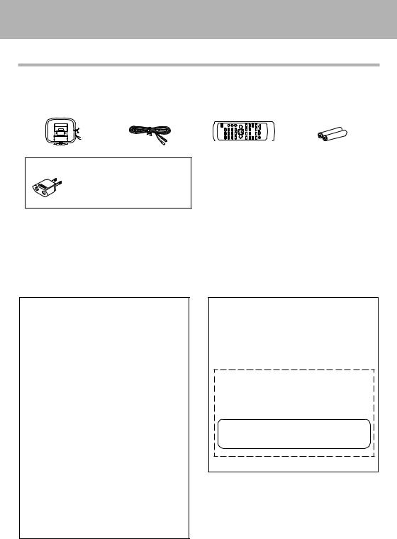
Unpacking
Unpack the unit carefully and make sure that all the accessories are present.
AM loop antenna (1) FM indoor antenna (1) Remote control unit (1) Batteries (R6/AA) (2)
AC plug adaptor (1)
Use to adapt the plug on the power cord to the shape of the wall outlet. (Accessory only for regions where use is necessary.)
If any accessories are missing, or if the unit is damaged or fails to operate, notify your dealer immediately. If the unit was shipped to you directly, notify your shipper immediately. Kenwood recommends that you retain the original carton and packing materials in case you need to move or ship the unit in the future.
Keep this manual handy for future reference.
For the U.S.A.
FCC WARNING
This equipment may generate or use radio frequency energy. Changes or modifications to this equipment may cause harmful interference unless the modifications are expressly approved in the instruction manual. The user could lose the authority to operate this equipment if an unauthorized change or modification is made.
NOTE:
This equipment has been tested and found to comply with the limits for a Class B digital device, pursuant to Part 15 of the FCC Rules. These limits are designed to provide reasonable protection against harmful interference in a residential installation. This equipment may cause harmful interference to radio communications, if it is not installed and used in accordance with the instructions. However, there is no guarantee that interference will not occur in a particular installation. If this equipment does cause harmful interference to radio or television reception, which can be determined by turning the equipment off and on, the user is encouraged to try to correct the interference by one or more of the following measures:
ÐReorient or relocate the receiving antenna.
ÐIncrease the separation between the equipment and receiver.
ÐConnect the equipment into an outlet on a circuit different from that to which the receiver is connected.
ÐConsult the dealer or an experienced radio / TV technician for help.
4 EN
For the U.S.A.
CAUTION
Use of controls or adjustments or performance of procedures other than those specified herein may result in hazardous radiation exposure.
In compliance with Federal Regulations, the following are reproductions of labels on, or inside the product relating to laser product safety.
KENWOOD CORPORATION
2967-3, ISHIKAWA-CHO,
HACHIOJI-SHI,
TOKYO, JAPAN
KENWOOD CORP. CERTIFIES THIS EQUIPMENT CONFORMS TO DHHS REGULATIONS NO. 21 CFR 1040.10, CHAPTER 1, SUBCHAPTER J.
Location: Back Panel
Downloaded from: http://www.usersmanualguide.com/
Before applying power
Contents
Caution : Read the pages marked  carefully to ensure safe operation.
Preparation section |
|
Before applying power ....................................... |
2 |
Safety precautions ......................................................... |
2 |
Special features ..................................................................... |
3 |
Accessories ............................................................................ |
4 |
System connection .................................................... |
6 |
Connection of the System Accessories ............................. |
6 |
Connection of Other Accessories |
|
(Commercially Available Parts) ..................................... |
8 |
Controls and indicators ............................................. |
9 |
Display ..................................................................................... |
9 |
Main unit ............................................................................... |
10 |
Operation of remote control unit ...................................... |
12 |
Basic section |
|
Basic use method ..................................................... |
14 |
Playback of CD ......................................................... |
16 |
Playback of TAPE ..................................................... |
18 |
Receiving broadcast station .................................. |
20 |
Collective presetting of stations ....................................... |
21 |
Channel space setting ........................................................ |
21 |
Tuning to a non-preset radio station |
|
(Auto tuning, Manual tuning) ....................................... |
22 |
One-by-one presetting (Manual preset) .......................... |
22 |
RDS (Radio Data System) (For U.K. and Europe) ........ |
23 |
Searching for a desired program type (PTY search) .... |
24 |
Recording on TAPE .................................................. |
26 |
As an ENERGY STAR¨ Partner, Kenwood Corporation has determined that this products meets the ENERGY STAR¨ guidelines for
energy efficiency. This product can save energy. Saving energy reduces air pollution and lowers utility bills.
Application section |
|
Various CD playback features ............................... |
29 |
Listening to the desired sequence (program playback) .. |
29 |
Repeated playback .............................................................. |
31 |
Playing tracks in a random order (random playback) ..... |
32 |
Convenient recording methods ............................. |
33 |
One-touch edit recording (CD =TAPE) .......................... |
34 |
Program recording (CD =TAPE) ...................................... |
35 |
Listening to an AUX input source .......................... |
36 |
Clock adjustment ..................................................... |
37 |
Timer operation ........................................................ |
38 |
Sleep timer (SLEEP) ............................................................. |
38 |
Setting the timer program |
|
(PROG. TIMER) ................................................................. |
39 |
Knowledge sections |
|
Important Items ......................................................... |
43 |
Maintenance ........................................................................ |
43 |
Reference .............................................................................. |
43 |
In case of difficulty .................................................. |
45 |
Specifications ........................................................... |
48 |
5 EN
Downloaded from: http://www.usersmanualguide.com/
System connection
Connection of the System Accessories
System connection
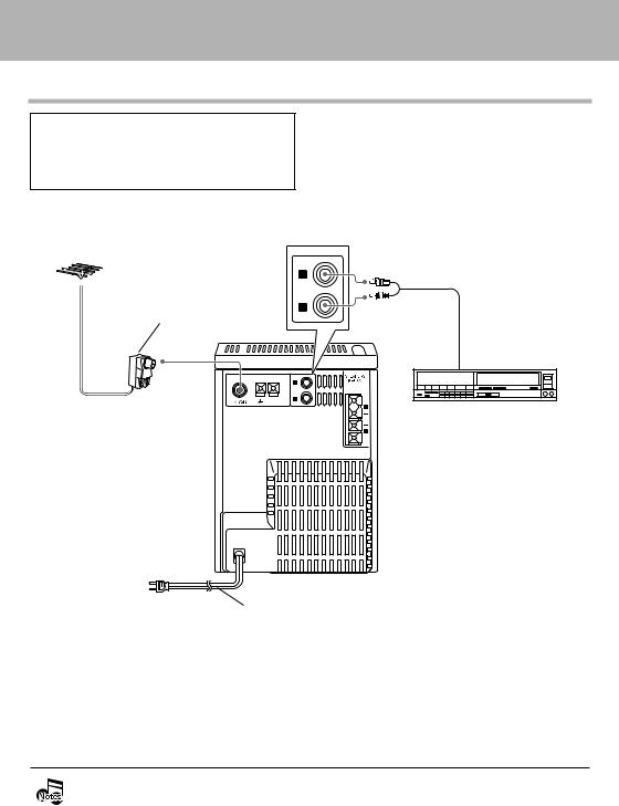
This figure shows the method of connection between the main unit and provided accessories.
CAUTION Note on Connection
Connect the components as shown in the diagram. Only plug the power cord into a power outlet once connections are completed.
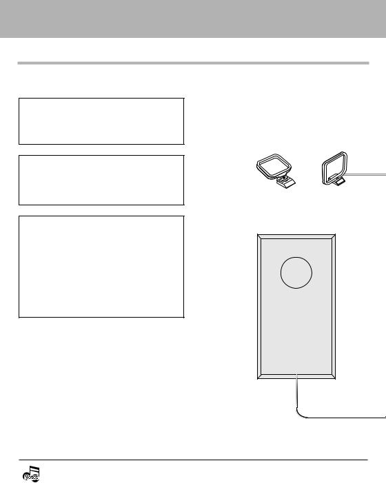
AM loop antenna
The supplied antenna is for indoor use. Place it as far as possible from the main system, TV set, speaker cords and power cord, and set it to a direction which provides the best reception.
CAUTION
The magnet in the speaker may cause color irregularity to the TV or PC monitor. Place the speaker farther away from the TV set or PC monitor.
\
Assemble |
AM loop antenna |
CAUTION
Be sure to adhere to the following, or proper ventilation will be blocked causing damage or fire hazard.
÷Do not place any objects impairing heat radiation onto the top of the unit.
÷Leave some space around the unit (from the largest outside dimension including projection) equal to or greater than, shown below.
Top panel : 50 cm Back panel : 10 cm
Speaker (Right) |
÷ Never short-circuit the "+" and "–" speaker cords.
÷ If the "+" and "–" polarity are inverted, the sound will be unnatural with unclear positioning of musical instruments, etc.
÷Be sure to insert all connection cords securely. If their connections are imperfect, the sound may not be produced or noise may interfere.
÷Before plugging or unplugging a connection cord, be sure to unplug the power cord from the wall AC outlet. If connection cords are plugged or unplugged with the power cord left plugged in, malfunction or damage may result.
6 EN
Downloaded from: http://www.usersmanualguide.com/

Malfunction of microcomputer
If operation is not possible or erroneous display appears even though all connections have been made properly, reset the microcomputer by referring to "In case of difficulty". t
System connection
FM indoor antenna
The supplied antenna is for temporary indoor use only. For stable signal reception, we recommend to use an outdoor antenna. Remove the indoor antenna if you connect to an outdoor antenna.
1 Connect the antenna to the antenna terminal.
2 Locate the position providing good reception condition.
3 Fix the antenna.
ANTENNA |
AM |
FM indoor antenna |
ANTENNA |
AM |
|
L |
AUX
IN
R
L
R |
Speaker (Left)
VOLTAGE SELECTOR 110V/220V
L
POWER cord
TO WALL AC OUTLET
R
Speaker cord
How to connect speaker cords to the main unit
1 |
2 |
3 |
||
|
|
|
|
|
|
|
|
|
|
How to connect AM antenna cord to the main unit
1 |
2 |
3 |
7 EN
Downloaded from: http://www.usersmanualguide.com/
System connection
Connection of Other Accessories (Commercially Available Parts)
CAUTION Note on Connection
Connect the components as shown in the diagram. Only plug the power cord into a power outlet once connections are completed.
FM outdoor antenna
Antenna adaptor (Commercially Available Parts)
FM outdoor antenna
Lead the 75Ωcoaxial cable connected to the FM outdoor antenna into the room and connect it to the FM 75Ω terminal. Please remove the indoor antenna after an outdoor antenna has been installed.
L |
Audio cord |
|
AUX
IN
R
Audio output
ANTENNA |
AM |
|
L |
AUX
IN
R
 L
L
R |
VCR, Analog turntable with built-in RIAA equalizer (optional P-110), etc.
POWER cord
TO WALL AC OUTLET
÷ In case an associated system component is connected, also read the instruction manual of the component. ÷ Be sure to insert all connection cords securely. If their connections are imperfect, the sound may not be
produced or noise may interfere.
÷Before plugging or unplugging a connection cord, be sure to unplug the power cord from the wall AC outlet. If connection cords are plugged or unplugged with the power cord left plugged in, malfunction or damage may result.
8 EN
Downloaded from: http://www.usersmanualguide.com/
Controls and indicators
Display
System connection
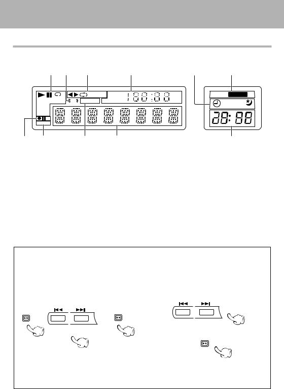
The displays given in this manual are approximations only. They may differ from what actually appears on
the display. |
|
|
|
|
|
1 |
2 |
3 |
4 |
|
|
1 |
TAPE EQ. TOTAL FM |
|
|
|
ST |
RDS PTY REMAIN AM |
|
|
PGM |
|
|
|
|
RDM |
|
|
|
|
O.T.E. |
|
|
|
8 |
7 |
|
6 |
5 |
1CD-related indicators
2STEREO tuning indicator
3Tape-related indicators
4Time display indicators, Numeric information display
5Character information display
6RDS-related indicators (For Europe and U.K.)
9 |
0 |
kHz |
LOUD EX.BASS |
|
MHz
1 2 A.P.S.
!
7 O.T.E. (One-Touch Edit) indicator
8Tape-related indicators
(Recording indicator, pause indicator)
9Timer-related indicators, APS indicator
0 EX.BASS indicator, LOUD (Loudness) indicator
! Clock indicator
AUTO POWER SAVE function
When the unit is ON and the unit is left for 30 minutes with CD or TAPE not operating, the unit is switched off automatically by this function. This is convenient when you forgot to switch off the unit. This function can be activated or deactivated by the following operation.
1 Select "APS |
?". |
2 Select "APS ON" or "APS OFF". |
mode |
|
set/sound |
\ |
|
\ |
3 Set it.
set/sound
(Press the set/sound key while the "?" mark is blinking.)
÷When the TUNER or AUX input is selected, APS operates only when the volume is set to zero or when MUTE is on.
9 EN
Downloaded from: http://www.usersmanualguide.com/
ControlsSystemandconnecindicatorsion
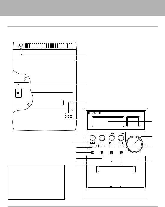
Main unit
Top view
phones |
BEAT |
1 |
2 |
push open |
1
2 |
|
3 |
Front view |
|
4 |
POWER
(For U.S.A. and Canada)
Standby mode
While the standby indicator is lit, a small amount of power is supplied to the system to back up the memory. This is called standby mode. Under the condition, the system can be turned ON by the remote control unit.
|
AUX |
TUNER/band |
CD |
TAPE |
volume |
8 |
|
|
|
|
5 |
|
|
|
Tuning |
|
|
|
|
|
Mode |
|
|
9 |
|
|
|
|
6 |
standby/timer |
|
time |
|
|
|
0 |
remote |
rec |
mode |
set/sound |
|
|
|
|
|
|
|
! |
|
|
|
|
0 push open |
|
|
|
|
7 |
|
@ |
|
|
|
|
|
# |
|
|
|
|
|
About the one-touch operation function
This unit incorporates the one-touch operation function for the user's convenience.
With this function, pressing any key enclosed in  while the unit is in standby mode immediately start playback (or reception).
10 EN
Downloaded from: http://www.usersmanualguide.com/
ControlsSystemandconnecindicatorsion
1 Headphone jack |
% |
Connect headphone with a stereo mini-plug (optionally available).
2 BEAT CANCEL switch |
¶ |
3 0 CD lid |
^ |
To load or eject a CD, press the area marked 0 push open on the CD lid to open it.
4 Display panel |
|
5 volume knob |
$ |
Turn this knob for volume adjustment. |
|
6 4 and ¢ multi control keys |
|
In the normal mode, these are used to |
|
Ð skip CD tracks |
& |
Ð fast forward or rewind tape |
( |
Ð select a preset radio station |
) |
In the menu mode (selected by pressing the mode key), press these buttons to select the desired menu item. To set or enter setting of the menu item, press the set/sound key.
mode |
set/sound |
|
|
\ |
\ |
Standby mode:
Press to display the clock.
Each press switches the mode.
 Clock display on
Clock display dimmed
Clock display off
7 Cassette holder |
* |
To load or eject a cassette tape, press the area marked 0 push open on the cassette holder to open it.
8 Basic operation keys |
|
AUX key |
fl |
Press to reproduce the external source component connected to the AUX (analog auxiliary input) jacks.
TUNER /band key |
) |
Press to select the TUNER input.
This key is also used to select the received broadcast band.
CD 6 key |
^ |
Press to select the CD input and start playback. During CD playback, press to pause.
TAPE 2 3 key |
* |
Press to select the TAPE (cassette deck) input and start playback of a tape. Pressing this key during tape playback switches the tape transport direction.
¥Pressing these (multi control keys) switches the display contents.
"TAPE RVS" (
"AUTO PRESET ?" or "AUTO MEMORY ?" ¡
(Only when the TUNER input is selected)
"INPUT ?" fl
(Only when the AUX input is selected)
9 POWER key (For U.S.A. and Canada) |
$ |
|
|
key (For other countries) |
$ |
|
||
|
||
Press to set the unit to On or Standby.
standby/timer indicator
Lights up when the unit is set to the Standby mode of power.
Red Green Off
"TIMER |
?" |
· |
"TIME ADJUST ?" |
‡ |
|
"APS |
?" |
9 |
¥The function of these keys returns to the normal mode when they have not been operated for 20 seconds.
7 Tuning Mode key
CD, TAPE : |
&( |
Press to stop a disc or tape operation. |
|
TUNER : |
™ |
Press to switch between the AUTO (auto tuning, stereo reception) and MONO (manual tuning, monaural reception) modes.
0 Remote sensor |
# |
This window receives signals from the remote control unit.
! rec key |
¶ |
Press to start tape recording. Pressing this key during recording initiates record-pause after leaving a nosound blank of about 4 seconds.
@ mode key |
9 |
Press to switch the function of the 4 and ¢ keys to menu select mode. Press again to reset the function of the 4 and ¢ keys to normal mode.
# set/sound key |
9 |
Press to select EX. BASS or LOUD sound effect or press to set or enter an item selected with the 4 and ¢ keys.
11 EN
Downloaded from: http://www.usersmanualguide.com/
ControlsSystemandconnecindicatorsion
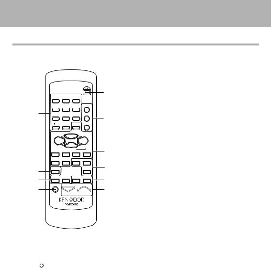
Operation of remote control unit
The keys on the remote control unit with the same names as on the main unit have the same function as the keys on the main unit.
|
|
|
|
POWER |
|
|
|
|
|
|
1 |
|
1 |
2 |
3 |
|
|
|
4 |
5 |
6 |
SLEEP |
|
7 |
7 |
8 |
9 |
PGM |
|
|
|
|
|
|
2 |
|
10 |
0 |
SET |
CLEAR |
|
|
|
CD 6 |
|
|
|
|
TUNER/BAND |
|
TAPE 23 |
|
|
|
|
|
AUTO/MONO |
|
|
|
|
STOP 7 |
|
3 |
|
|
4 P.CALL ¢ |
1 TUNING ¡ |
|||
|
AUX |
ENTER |
O.T.E. |
REC |
|
|
• PTY • |
|
|
|
4 |
8 |
TIME DISPLAY |
|
|
TAPE EQ. |
|
|
|
|
|
|
|
9 |
SOUND |
TONE |
REPEAT |
RANDOM |
5 |
|
|
|
|
||
0 |
|
|
|
|
6 |
|
MUTE |
|
VOLUME |
|
|
 RC-F0300
TUNER/ BAND key |
) |
CD 6 key |
^ |
STOP 7/AUTO/MONO key |
&™ |
TAPE 2 3 key |
* |
4 P.CALL ¢ keys |
|
CD : |
& |
Used to skip CD tracks. |
|
TAPE : |
( |
Used to fast forward or rewind tape. |
|
TUNER : |
) |
Used to receive a preset radio station.
1 TUNING ¡ keys
CD, TAPE : &(
Used to fast-forward or fast-reverse the played audio.
TUNER : |
™ |
Used to select a radio station. |
|
AUX key |
fl |
Press to reproduce the external source component connected to the AUX (analog auxiliary input) jacks.
|
|
|
|
ENTER key |
™ |
|
|
|
|
|
Press to enter a radio station in the preset memory of |
||
Infrared ray system |
|
the tuner. |
|
|||
Model : RC-F0301E (For UK and Europe) |
|
|
||||
|
|
|
||||
|
|
: RC-F0301 (For other countries) |
|
4 O.T.E. key |
fi |
|
|
|
|
|
|||
|
|
|
|
Press to start recording CD onto a tape with one-touch |
||
1 POWER |
|
key |
$ |
operation. |
|
|
|
|
|||||
|
|
|||||
Press to set the unit to On or Standby. |
|
Pressing this key during CD playback records only the |
||||
|
|
|
||||
2 SLEEP key |
° |
track being played onto tape. Pressing it while CD is in |
||||
stop state will record all the CD tracks onto tape. |
||||||
|
|
|
|
|||
Press to set the sleep timer. |
|
REC key |
¶ |
|||
PGM key (CD) |
ª |
|||||
TAPE EQ. key |
( |
|||||
|
|
|
|
|||
Press to program tracks in the desired sequence.
CLEAR key (CD) |
º |
5 REPEAT key (CD) |
⁄ |
|
|
||
Press to clear a programed track(s). |
|
Press for setting repeated playback. |
|
|
|
|
|
3 Basic operation keys |
|
RANDOM key (CD) |
¤ |
Press for setting playback of tracks in a random order.
SET key
Press to set or enter an item selected with the 4 and ¢ keys.
12 EN
Downloaded from: http://www.usersmanualguide.com/
ControlsSystemandconnecindicatorsion
6 VOLUME keys |
$ |
9 SOUND key |
% |
|
Press to adjust the volume. |
|
Press to switch the sound effect to EX.BASS or |
||
7 Numeric keys |
&™ |
LOUD. |
|
|
TONE key |
% |
|||
Used to select a CD track number or recall a preset |
||||
|
|
|||
station of the tuner. |
|
Press to adjust the tone. |
|
|
|
|
|
||
8 ÷PTY ÷TIME DISPLAY key (For Europe and U.K.) |
0 MUTE key |
% |
||
|
&¢ |
Press to mute the audio temporarily. |
|
|
|
|
|
||
Used at the time of program type detection.
Press to switch the displayed time information on CD.
TIME DISPLAY key (For other countries) &
Press to switch the displayed time information on CD.
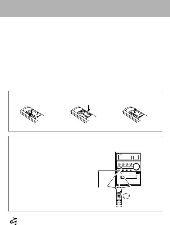
Loading batteries
1 Remove the cover. |
2 Insert batteries. |
3 Close the cover. |
÷ Insert two R6 ("AA"-size) batteries following the polarity indications.
Operation |
Operating range (approx.) |
After plugging the power cord of this unit, press the POWER ( ) key of the remote control unit to turn the system ON. When the system is turned ON, press the key of the function to be operated.
÷When pressing more than one remote control keys successively, press the keys securely by leaving an interval of 1 second or more between keys.
Remote sensor
6 m
30˚ |
30˚ |
÷ The provided batteries are intended for use in operation checking, and their service life may be short. ÷ When the remote controllable distance becomes short, replace both of the batteries with new ones.
÷If direct sunlight or the light of a high-frequency fluorescent lamp (inverter type, etc.) is incident to the remote sensor, malfunction may occur. In such a case, change the installation position to avoid malfunction.
13 EN
Downloaded from: http://www.usersmanualguide.com/
Basic use method
Basic use method
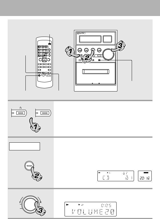
The system is switched ON or STANDBY
Enhancement of bass
0 push open
Enhancement of bass
Muting the sound temporarily Tone adjustment
POWER
or
 standby/TIMER
  standby/TIMER
1. Set the key (or POWER key) to ON.
Pressing the key (or POWER key) when the unit is ON turns it off (Standby mode of power).
÷Pressing the TUNER/band, CD 6, TAPE 2 3 or AUX key also turns power on and starts playback (reception) of the corresponding input. (One-touch operation)
÷When the CD or TAPE input is selected while the corresponding disc or tape has been loaded, it immediately starts to play.
Example:
To select the CD input
CD 


2. Selecting the desired output.
CD |
^ |
TAPE |
* |
TUNER (Broadcasts) )
AUX (External input) [Adjusting the AUX input level fl]
÷Pressing the TUNER/ band, CD 6, TAPE
EX.BASS
2 3 or AUX key se-
lects the correspond-
ing input.
When CD has been selected.
The volume |
volume |
The volume |
3. |
Volume adjustment. |
|
|
|
||
decreases |
|
increases |
|
|
÷ The display shows a reference value.
Volume display
14 EN
Downloaded from: http://www.usersmanualguide.com/
Basic use method
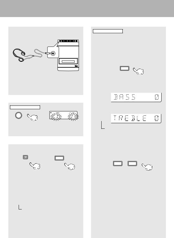
Listening through headphone |
Tone adjustment |
Insert the headphone plug into the headphone jack.
phones |
(Top view) |
÷Headphone with a stereo mini plug can be connected.
÷The sound from all speakers are cut off.
Muting the sound temporarily
Remote control unit only
MUTE
Blinks
÷Press again to resume the original volume.
÷This is also canceled when the volume is changed.
Enhancement of bass
Main unit |
|
Remote control unit |
set/sound |
SOUND |
|
Each press switches the modes as follows.
 1 "EX.BASS" lights.
The low frequencies are enhanced regardless of the current volume level.
2"LOUD" (Loudness) lights.
The low frequencies are enhanced according to the current volume level. (Effective during low-volume listening.)
3Both indicators off.
Canceled.
÷Adjusting the tone while the "LOUD" or "EX.BASS" indicator is lit turns it off and cancels the sound enhancement mode.
Remote control unit only
The lowest and highest frequency bands can be adjusted independently.
1 Select the frequency band.
TONE
Each press switches the operation.
 1 "BASS" (low frequency) adjustment
2"TREBLE" (high frequency) adjustment
3Normal mode
(Go to step 2 within 8 seconds.)
2 Adjust.
4 P.CALL 4
(To adjust the other frequency band, repeat steps 1 and 2 for it.)
÷The levels of both "BASS" and "TREBLE" can be adjusted in 2 steps in the range between Ð 8 and +8.
÷Adjusting the tone while the "LOUD" or "EX.BASS" indicator is lit turns it off and cancels the sound enhancement mode.
15 EN
Downloaded from: http://www.usersmanualguide.com/
 Loading...