


RXD-M57MP-S
Table of contents
 Loading...
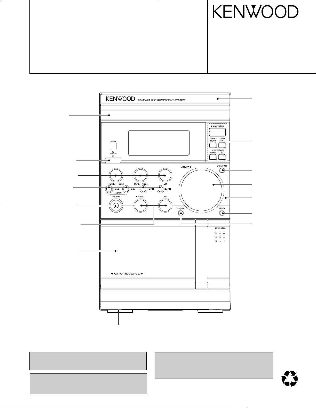
COMPACT Hi-Fi COMPONENT SYSTEM
70%
RXD-M57MP-H/M57MP-S
SERVICE MANUAL
(HM-537MP)
CD Door *
(A29-)
Knob(Power)
(K29-8417-08)
Knob(Function)
(K29-8414-08)
Knob(Play) *
(K29-)
Phone jack
(E11-0981-08)
Knob(Stop/REC)
(K29-8415-08)
© 2004-8 PRINTED IN KOREA
B51-5923-00 (K/K) 339
Front cabinet ass’y *
(A60-)
Knob(Open/Close)
(K29-8416-08)
Knob(EQ/Bass) *
(K29-)
Knob(Volume)
(K29-8413-08)
Control panel *
(A21-)
Knob(Demo) *
(K29-)
Knob(Prog) *
(K29-)
Cass lid ass’y *
(A53-)
Rubber foot
(G11-2961-08)
* Refer to parts list on page 20.
In compliance with Federal Regulations, following are reproduction of labels on, or inside the product relating to laser
product safety.
Caution : No connection of ground line if disassemble
the unit. Please connect the ground line on
rear panel, PCBs, Chassis and some others.
KENWOOD Corp. certifies this equipment conforms to DHHS
Regulations No.21 CFR 1040. 10, Chapter 1, subchapter J.
DANGER : Laser radiation when open and interlock defeated.
AVOID DIRECT EXPOSURE TO BEAM.
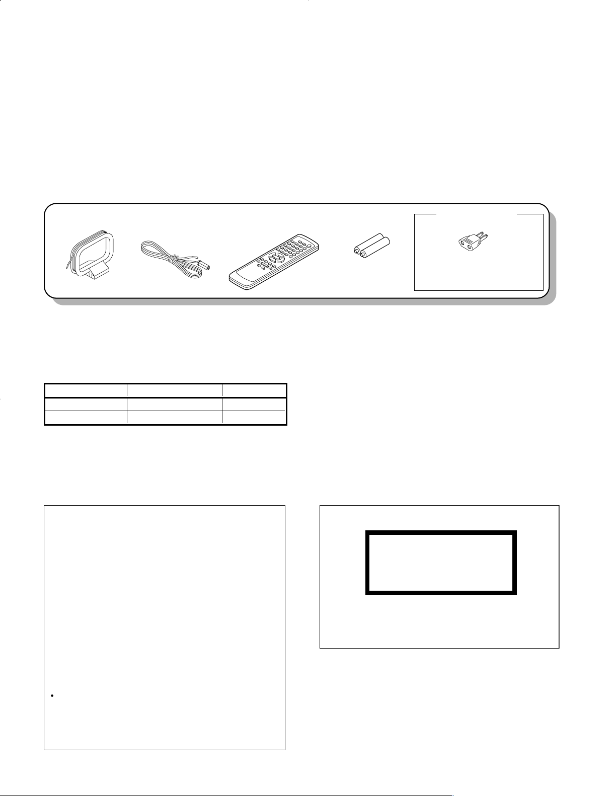
Remote control unit (1)
(A70-1688-08)
AM loop antenna (1)
(T90-0908-08)
FM ANT Wire (1)
(T90-0918-08)
Batteries (R6/AA) (2)
AC plug adapter (1)
(E03-0115-05)
Use to adapt the plug on the power
cord to the shape of the wall outlet.
(Accessory only for regions where
use is necessary.)
RXD-M57MP
CLASS 1 LASER PRODUCT
LASER KLASSE 1
APPAREIL A LASER DE CLASSE 1
LUOKAN 1 LASERLAITE
KLASS 1 LASERAPPARAT
The marking this product has been classified as Class 1.
It means that there is no danger of hazardous radiation
outside the product.
Location: Bottom
Resetting the Microcomputer
The microcomputer may malfunction (unit cannot be operated, or shows an erroneous display) if the power cord is unplugged while the
power is ON, or due to some other external
factor. If this happens, execute the following
procedure to reset the microcomputer and
return the unit to its normal operating condition.
Plug in the AC power cord to the wall outlet,
and within 5 seconds, press and hold down
the
7
button and press CD button.
Please note that resetting the microcomputer
will clear the contents of the memory and
return the unit to the state it was in when it
left the factory .
SYSTEM RECEIVER SPEAKERS
HM-537MP-H RXD-M57MP-H LS-M57-H
HM-537MP-S RXD-M57MP-S LS-M57-S
CONTENTS / ACCESSORIES / CAUTIONS
CONTENTS
CONTENTS / ACCESSORIES / CAUTIONS...............2
EXTERNAL VIEW ........................................................3
ADJUSTMENT .............................................................4
PC BOARD ..................................................................8
ACCESSORIES
SCHEMATIC DIAGRAM ............................................13
EXPLODED VIEW .....................................................19
PARTS LIST...............................................................20
SPECIFICATIONS..................................BACK COVER
SYSTEM CONFIGURATION
CAUTIONS
2
220-240V
110-120V
VOLTAGE
SELECTOR
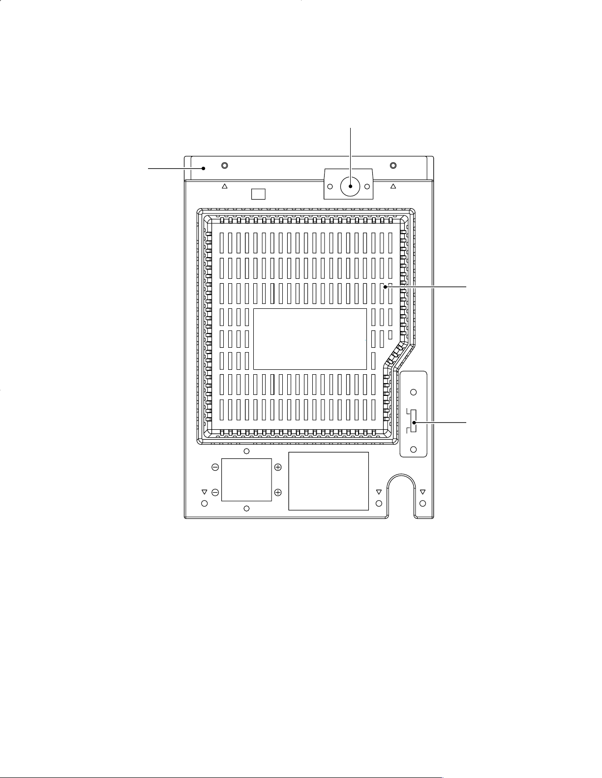
Top cabinet
(A01-3943-08)
RXD-M57MP
EXTERNAL VIEW
FM 75 ohm Ant.
(E70-0200-08)
Rear cabinet
(A80-4494-08)
* Refer to parts list on page 20.
Voltage SW. *
(S62-0124-08)
3
RXD-M57MP
SERVICE ADJUSTMENT
Lubrication
The mechanical parts are factory coated with a thin coat of light grease and should not require further
lubrication. If a light grease is applied, be careful not to get any grease on the play/record head or erase
head, hubs, pulleys, tapes reels, drive belts, or switches. Use a good lubricant such as Silicon Lube G322L
or Lubricate.
Service Check
Before aligning the mechanism, wipe off any accumulated dirt with denatured alcohol. Wipe around parts
where the tape contacts and around all rotating parts. Drive belts are specially processed. Do not clean
them with alcohol.
Mechanical Torque
Use a cassette type torque gauge and check the tape mechanism.
Take-up torque 35 to 70 g-cm
Rewind torque 50 g-cm min.
Fast forward torque 50 g-cm min.
Pinch Wheel Pressure
No adjustment to the pinch roller spring is necessary. It should be sufficient to give at least 40 g-cm pull
force.
Tape Head Servicing
Each time the unit is serviced, the face of all heads should be thoroughly cleaned with denatured alcohol or
commercial head cleaning solution. The playback head should be demagnetized with a commercial
demagnetizer. Accumulation of tape oxide during normal operations can cause problems, including loss of
high frequencies and wow and flutter.
Erase Head
The erase head is properly aligned when the tape rides directly between the tape guide on the head without
crinkling the tape.
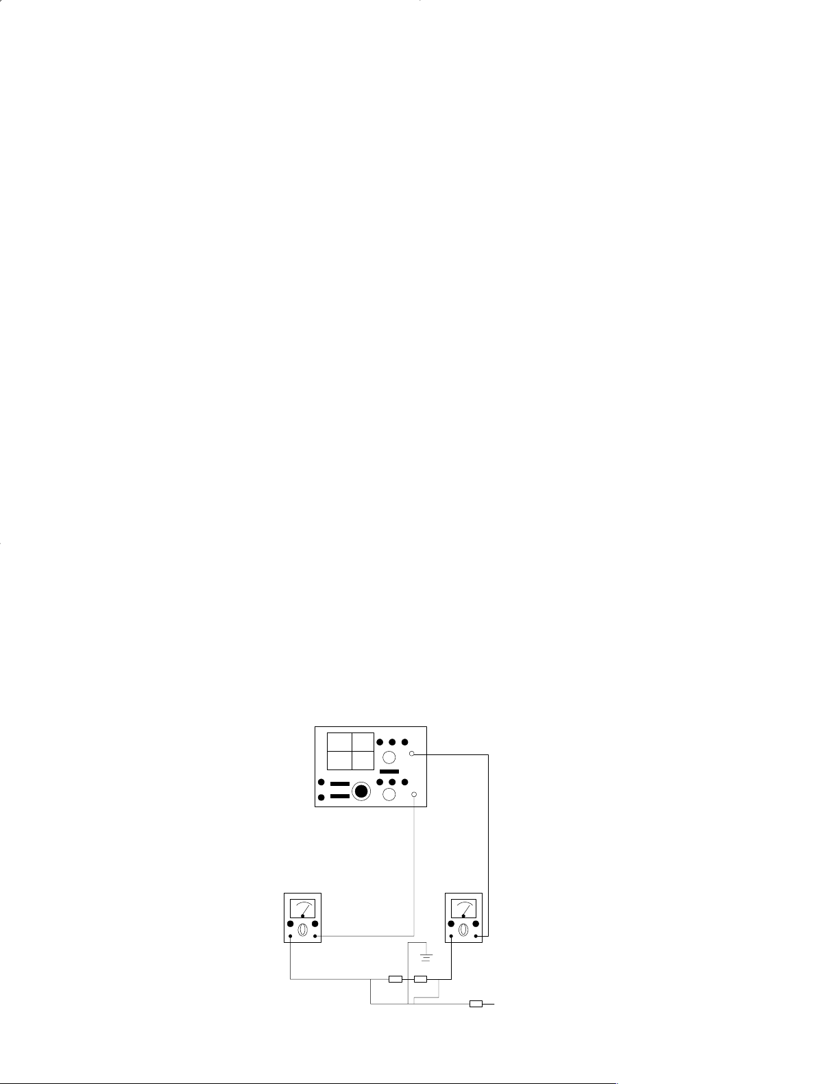
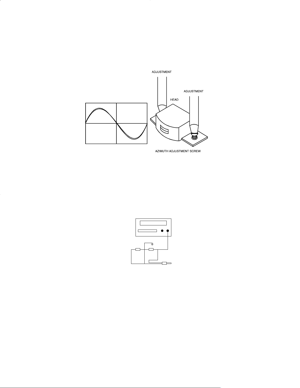
Play/Record and Playback Head Azimuth Adjustment
To adjust the play/record and playback head azimuth screw:
1. Connect two (2) VTVMs and a dual trace scope to the stereo headphone jack (as shown) with a 32
ohm dummy load. (See Figure 1.)
VTVM VTVM
DUMMY LOAD
JK400
SCOPE
CH1
CH2
Figure 1. Azimuth Adjustment
ADJUSTMENT
4
ADJUSTMENT
2. Insert a 10 kHz test tape (Teac MTT-1141V or Equivalent) into the tape mechanism and play it back.
3. While playing back the test tape, slowly turn the azimuth adjusting screw until the amplitude of both
channel output waveforms is maximum and in phase. Note: Reiteration adjusting Right, lift the screw,
until the amplitude of both channel output waveform is maximum. (See Figure 2.)
4. Secure the azimuth screw in place with glue or paint after making the adjustment.
Figure 2. Head Output Signal
Tape Speed Adjustment
1. Set the function switch to TAPE.
2. Connect a frequency counter with a 32 ohm dummy load to the stereo headphone jack. (See Figure 3.)
FREQUENCY COUNTER
DUMMY LOAD
JK400
Figure 3. Tape Speed Adjustment
3. Insert and play back a 3 kHz test tape (Teac MTT-111 or Equivalent) into the tape mechanism.
4. Insert an insulated alignment tool and adjust the tape speed potentiometer (MOTOR) until the
frequency counter indicates 2940 Hz to 3090 Hz.
Bias Oscillator Frequency and Level Adjustment
1. Set the function switch to TAPE and the record and play tape mechanism to RECORD.
2. Connect a VTVM and frequency counter to test point R/P HEAD.
3. Adjust bias oscillator coil L203 until the frequency counter indicates 67 kHz ± 0.5 kHz.
RXD-M57MP
5
RXD-M57MP
TUNER ALIGNMENT PROCEDURE
Equipment needed:
1. AM Signal generator
2. FM Signal generator
3. DC Voltage meter
4. Oscilloscope
5. Output meter (VTVM)
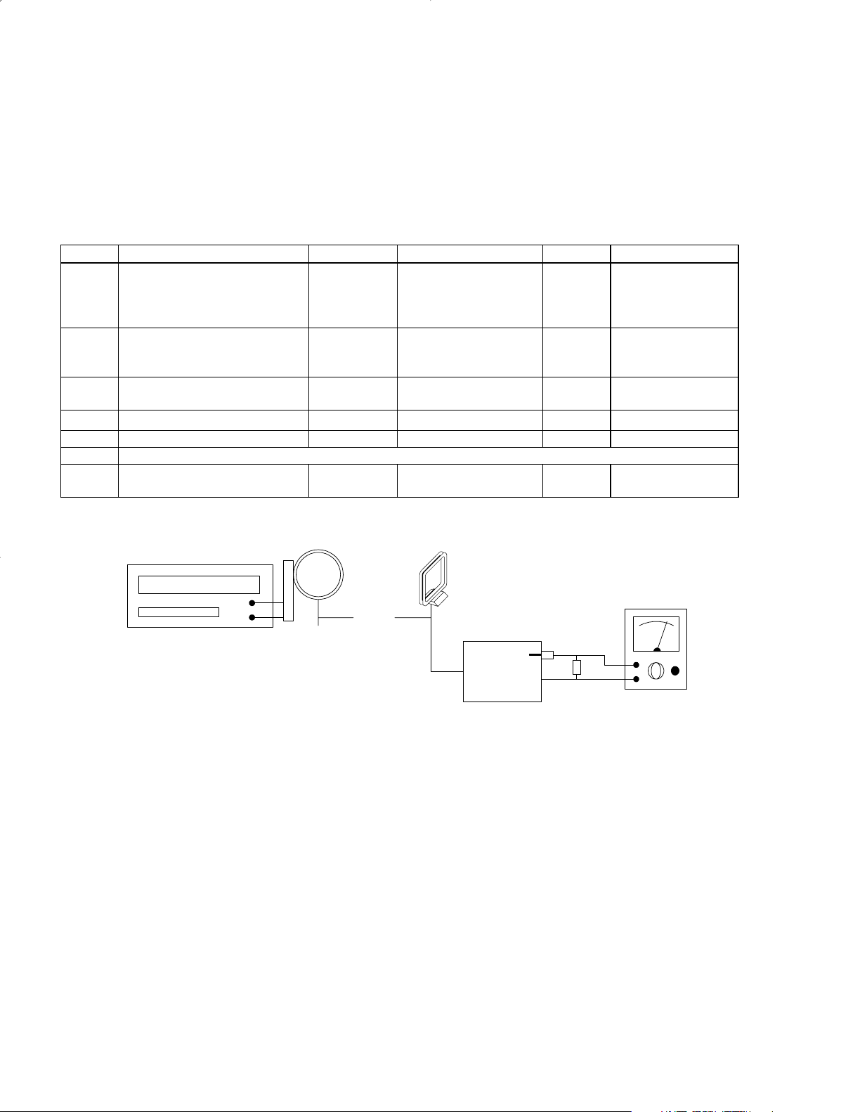
AM Alignment
Step S/G Frequency Dial Setting Indicator Adjust Remarks
1 450 kHz (1 kHz 30% mod.) 612 kHz Connect
oscilloscope or
VTVM to speaker
jack
T101 Adjust for
maximum
output
2 531 kHz (1 kHz 30% mod.) Low end Connect DC voltage
meter to test point Vt
and ground
L102 Adjust until
Vt equal to
1.5 – 0.05V
3 1602 kHz (1 kHz 30% mod.) High end Same as step 2 Confirm Vt:
6.5~8.5V
4 612 kHz (1 kHz 30% mod.) 612 kHz Same as step 1 L103 Maximum output
5 1404 kHz (1 kHz 30% mod.) 1404 kHz Same as step 1 TC101 Maximum output
6 Repeat steps 4 and 5 to minimize tracking error
7 999 kHz
(1 kHz 30%mod.)
999 kHz
Same as step 1 Offset is less than
6 dB.
60 cm
AM SIGNAL GENERATOR
AM LOOP ANT
AM LOOP
ANTENNA
DUMMY LOA D
VTVM
TEST UNIT
Figure 4. AM IF/RF Tracking
ADJUSTMENT
6

ADJUSTMENT
FM Alignment:
TEST UNIT
Figure 5. FM Band Frequency Coverage Alignment
Connect FM S/G to ANT inputs (mod 1 kHz 22.5kHz dev.)
Step S/G Frequency Dial Setting Indicator Adjust Remarks
1 87.5 MHz Low end Connect DC Voltage
meter to test point Vt
and ground
Confirm Vt:
1.7 ± 0.2V
2 108 MHz High end Same as step 1 Confirm Vt:
8.5 ± 1V
Figure 6. FM Band/Tracking
FM GENERATOR
DUMMY
ANTENNA
TP1
TEST UNIT
DUMMY
LOAD
VTVM
OSCILLOSCOPE
Vt
GROUND
DC
RXD-M57MP
7
Loading...