


RXD-803
Table of contents
 Loading...
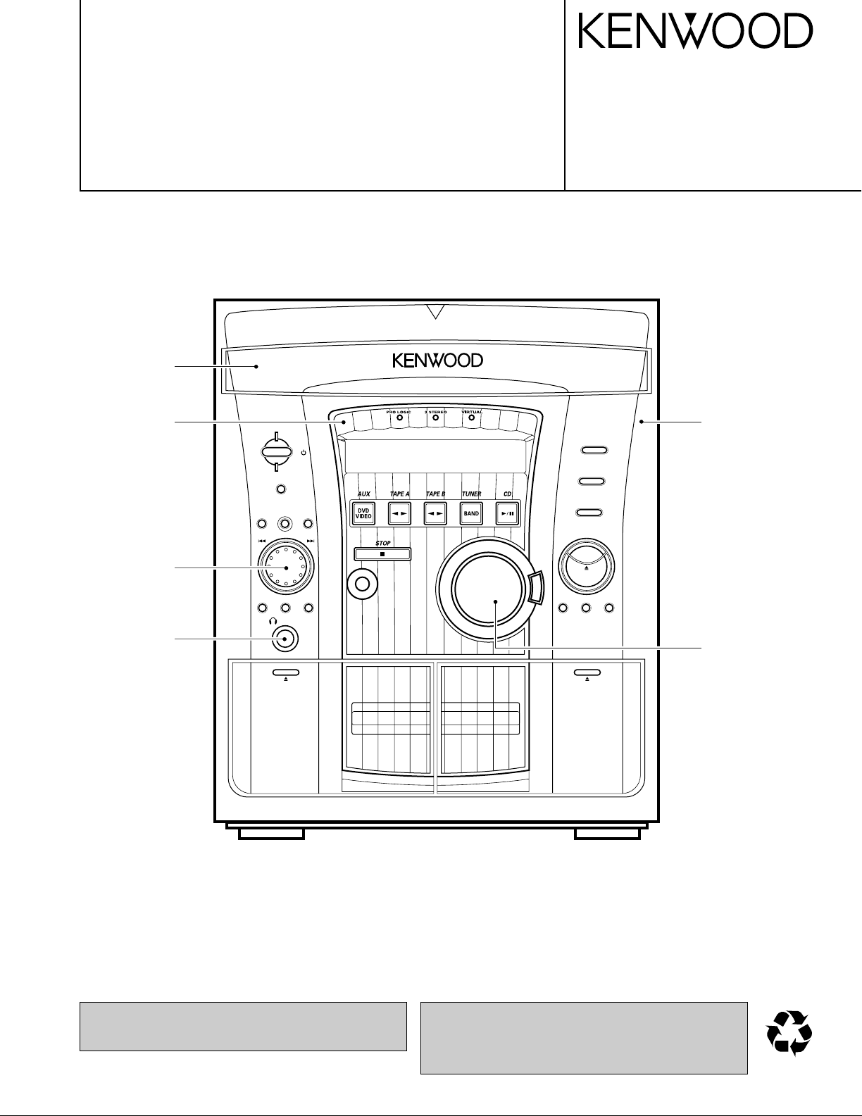
MINI HiFi COMPONENT SYSTEM
RXD-803/803E/853/853E/A83
SERVICE MANUAL
(XD-803~A83)**
© 2000-5/B51-5622-00 (K/K) 3633
70%
DISC
1
DISC
2
DISC
3
STANDBY
TIMER
DISPLAY/DEMO
MENU
SELECTBACK ENTER
SOUND
CONTROL
TUNING
MODE
M
U
L
T
I
C
O
N
T
R
O
L
REC/ARM
REVERSE
MODE
TAPE EQ.
PHONES
DISC SKIP
OPEN/
CLOSE
E
X
.
B
A
S
S
PUSH
OPEN
PUSH
OPEN
DECK
PLAY
A
DECK
REC/PLAY
B
VOLUME
CONTROL
I/
Panel ass'y
(A60-1771-31)
Knob
(K29-7721-04)
Panel
(A29-1082-12)
Front glass
(B10-3582-02)
Knob
(K29-7722-04)
Phone jack
(E11-0280-05)
In compliance with Federal Regulations, following are repro-
ductions of labels on, or inside the product relating to laser
product safety.
**Refer to page 2 if you want to know system configuration.
KENWOOD-Crop. certifies this equipment conforms to DHHS
Regulations No. 21 DFR 1040. 10, Chapter 1, Subchapter J.
DANGER : Laser radiation when open and interlock defeated.
AVOID DIRECT EXPOSURE TO BEAM
Illustration is RXD-853(M).

Unplug the power cord from the power outlet then,
while holding the ENTER key depressed, plug the
power cord again.
÷ Please note that resetting the microcomputer clears the
stored contents and returns to the factory set condition.
Operation to reset
The microcomputer may fall into malfunction (impossibility
to operate, erroneous display, etc.) when the power cord is
unplugged while power is ON or due to an external factor.
In this case, execute the following procedure to reset the
microcomputer and return it to normal condition.
(Main unit only)
ENTER
FM indoor antenna (1) AM loop antenna (1) Remote
(T90-0836-05) (T90-0852-05)
(T90-0837-05)
(A70-1367-05): RC-853....KPMXY
(A70-1368-05): RC-853E....TEE2
Battery cover (A09-1151-08)
control unit (1)
Use to adapt the plug on the power
cord tothe shape of the wall outlet.
(Accessory only for regions where
use is necessary.)
AC
(E03-0115-05)
plug adaptor (1)
Batteries (R6/AA) (2)
Surround speaker system
Surround speaker (2)
Speaker cord (2)
Speaker stabilizer (8)
Center speaker (1)
Speaker cord (1)
Speaker stabilizer (4)
SYSTEM CONFIGURATION
Cautions
RXD-803/803E/853/853E/A83
2
CONTENTS / ACCESSORIES
CONTENTS / ACCESSORIES / CAUTIONS............. 2
EXTERNAL VIEW.......................................................3
DISASSEMBLY FOR REPAIR....................................3
BLOCK DIAGRAM......................................................4
CIRCUIT DESCRIPTION............................................5
ADJUSTMENT..........................................................11
PC BOARD .............................................................. 13
SCHEMATIC DIAGRAM.......................................... 19
EXPLODED VIEW ....................................................35
PARTS LIST..............................................................37
SPECIFICATIONS ......................................Back cover
Contents
Accessories
SYSTEM MAIN UNIT DESTINATION SPEAKER SP CORD PARTS No. SPEAKER SP CORD PARTS No.
XD-803 RXD-803 E LS-N523 E30-5829-08 CRS-N503 E40-5542-05
XD-803E RXD-803E E2 LS-N523 E30-5829-08 CRS-N503 E40-5542-05
XD-853 RXD-853 YMXTE LS-N573 E30-5829-08 CRS-N553 E40-5542-05
XD-853E RXD-853E E2 LS-N573 E30-5829-08 CRS-N553 E40-5542-05
XD-853(M3) RXD-853 M LS-N573(M3) E30-5829-08 CRS-N553 E40-5542-05
XD-A83 RXD-A83 KP LS-N573 E30-5829-08 CRS-N553 E40-5542-05

RXD-803/803E/853/853E/A83
3
EXTERNAL VIEW
AC 220-
240V~
AC 110-
120V~
GND
FM
75
AM
ANTENNA
+
-
FRONT
SPEAKERS
DIGITAL
OPTICAL
(
6-16
)
R
L
L
R
FRONT
+
-
SURROUND
SPEAKERS
(
12-16
)
R
L
SUPER
WOOFER
PRE OUT
CENTER
SPEAKER
(
6-16
)
OUT
CENTER
SURROUND
SUB
WOOFER
6CH.
INPUT
Lock terminal board
(E70-0052-05)
Cover
(F07-1692-01)
Metallic cabinet
(A01-3739-11)
Slide switch
(S62-0001-05)
Pin jack
(E63-0095-05)
Lock terminal board
(E70-0045-05)
Pin jack
(E63-0116-05)
Pin jack
(E63-1008-05)
Oscillating module
(W02-1114-15)
Lock terminal board
(E70-0046-05)
Illustration is RXD-853(M).
DISASSEMBLY FOR REPAIR
BOTTOM SIDE
HOW to open the tray if not comes out.
(1) Turn the friction arm counterclockwise
using a screw driver and the like.
(2) Pull out the tray frontwards by hand
when the tray comes just out.
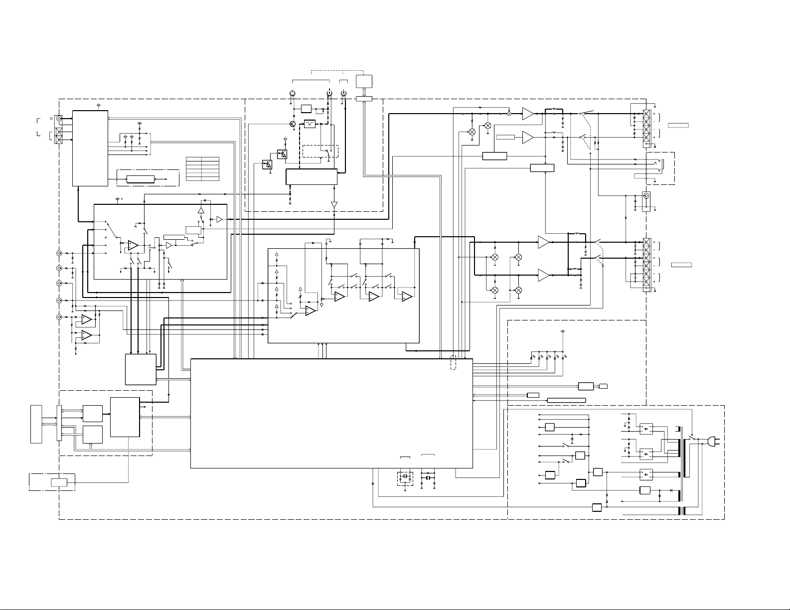
BLOCK DIAGRAM
CLK
PLL-CLK
PLL-CE
PLL-DO
SD
ST
PLL-DATA
S-LEVEL
DE-EMPH
R/P
Lch-OUT
Rch-OUT
+12V
REC
PB AMP
AMP
5V
(600mV)
DECK (1.2V)
CD (1.2V)
Lch-OUT
Rch-OUT
DIGITAL OUT
DATA
POWER RELAY
XIN
XOUT
XCIN
XCOUT
(10MHz)
(32.768KHz)
MAIN CLOCK
TIMMER CLOCK
MPX CLK
DATA
u-COM
TUNER
+
+
C1,C2
A,B
CANCEL
BEAT
OUT
IN
PROTECTION
ATT
MUTE
BEEP
+
PRO LOGIC
5V
TUNER
DECK
CD
VIDEO
DATA
CLK
LIN
LOUT
RIN
ROUT
COUT
SOUT
IFCK
DSP CS
IFDI
ACK
+
+
5V
9V
+
+
+
+
3STEREO
VIRTUAL
STANDBY
TIMER
LED CONTROL
DATA
CLK
STB
RST
Sch
Cch
MUTEATT.
-10dB
Lch
Rch
1M
A120/70
A/B
B1/2
LBASS2
SE CLK
S4
LTRE
LSELO
LIN
LBASS1
SE DATA
SE CE
C OUT
S OUT
S3
S2
S1
C1
C2
C4
C3
SE CE
SE DATA
SE CLK
+12V
+
+
+
+
+
+
+
+
+
S.CchSP
HP-DET
MUTEATT.
-10dB
CD
DECK
6ch INPUT
0dB
-6dB
0dB
TUNER
VIDEO -6dB
0dB
INPUT ATT.
(RECK=H)
R/PERASE
SURROUND
OSC
BIAS
BIAS TRAP
BA3126N
CXA1498S
OTHER ch
H.P.
Rch
Lch
RF AMP
AN8806SB
PICKUP/
LOADING
DRIVER
CD DSP
KEY
(X13)
TUNER PACK
FM75
ANT
B DECK
(X28)
DECK
MECHA
IC2
IC1
IC12
RDS
INPUT ATT .
M62498FP
L,RCH IN
IC1
CD MECHA
CDM-35
DIGITALOUT
(OPTICAL)
MAIN u-COM
M30622MA-A42FP
(X13)
Q3
Q1
IC1
-10dB
MUTE
IC2
IC4
(X14)
AMP
AM
J1
DEMODULATOR
J2
LOUDNESS
INPUT SELECTOR
INPUT VOL.
MAIN VOL.
3BAND TONE
L/R
FRONT
VOL.
SUB
(X32)
P
HEAD SW
PLAY/REC
PLAY BACK
/REC EQ.
A DECK
14,16
IC3
J2
SPEAKERS
(X14)
AMP
BASS REVISE
CIRCUIT
AC/DC
PROTECTION
SLch
SRch
X1
X2
GND
5V
AVR
D33
D32
GND
40V
AVR
-35V
AVR
12V
Q38
Q34
AVR
9V
Q31
5V
AVR
Q32
5V
AVR
X13,Q8
DECK (BIAS)
TUNER
DRIVER
LOADING
PICKUP DRIVER
CD DSP.RF AMP
CONTROL IC
ELECTRIC VOL
-40V
FIL
12V
MAIN
FIP
IC1
ED1
KEY1-3
BASS
VOLUME
FIP
DRIVER
REMOCON INTERFACE
BACKUP
u-COM
Q13,
CN2
IC11
MID TRE
SELECTOR
Zin=100K
DOLBY
DSP
IC14
OTHER CH
VIDEO/6CH
400mV IN
Cch IN
6CH
SLch IN
6CH
SRch IN
6CH
SUB WOOFER
6CH
(X14)
DECK (MECHA)
DOLBY PL DSP
AVR
5V
ELECTRIC VOL
(C,Sch)
(L,Rch)
DOLBY PL DSP
RDS
DECK
CD
D5
GND
-HB
+HB
+LB
-LB
HNA-15MM18T
J4
Cch
AMP
AMP
IC2
IC2
Q8Q6
IC1
IC13
VOLUME
ELECTRIC
J3
S.W. PRE-OUT
Q5 Q7
SPEAKERS
(X07)
E/T TYPE
ONLY
RXD-A83/803/803E/853/853E
E/T/M/X
DESTINATION
RXD-803/803E/853/853E/A83
4

RXD-803/803E/853/853E/A83
5
CIRCUIT DESCRIPTION
1. Initialization
1-1 Setting of the Initial Conditions
While pressing the [ENTER] key, plug the AC cord into AC
wall outlet.
1-2 Initializing Operation
• A Microcomputer is initialized for start when the AC power
is turned on when pressing the [ENTER] key.
At that time, CD and cassette mechanisms are also initial-
ized.
• During the initial conditions, the display shows *INITIAL-
IZE* and after that it will be returned to standby condition.
1-3 Initial Items
(1) AMPLIFIER
• POWER ON/STANDBY STANDBY
• VOLUME 14
• BALANCE CENTER
• INPUT SELECTOR TUNER
• SOURCE DIRECT OFF
• MUTE OFF
• AUTO POWER SAVE OFF
• AUX INPUT LEVEL -1
• AUX INPUT MODE 2ch(EXCEPT E,E2,T)
• DISPLAY MODE AUTO
(2) TUNER
• BAND FM
• FREQUENCY LOWEST FREQUENCY
• AUTO/MONO AUTO
• PRESET CHANNEL – – ch
(3) CASSETTE DECK
• REVERSE MODE REVERSE
• TAPE A/B B
• TAPE DIRECTION FORWARD
(4) CLOCK
• CLOCK 0:00(E,E2,T)/12:00am(OTHER)
• Program Timer Recoding
ON TIME 0:00(E,E2,T)/12:00(OTHER)
OFF TIME 0:00(E,E2,T)/12:00(OTHER)
• Program Timer Play
ON TIME 0:00(E,E2,T)/12:00(OTHER)
OFF TIME 0:00(E,E2,T)/12:00(OTHER)
• Program on Mode OFF
• SLEEP TIMER OFF
(5) Equalizer
• Equalizer OFF
• CUSTOM EQ.1~3 FLAT
• EX. BASS ON
• DSP OFF
• SURROUND OFF
1-4 Mechanism Initialization
1-4-1 CD Mechanism
• If a mechanism error occurs "C" is indicated on the dis-
play.
1-4-2 DECK mechanism
• When the initial condition becomes NG for the third
time,decide the error.
The error condition is displayed as "X" on the display.
1-4-3 Error display
• If both mechanism (CD/DECK) error occur, the display is
indicated as follows.
• C
X ERR
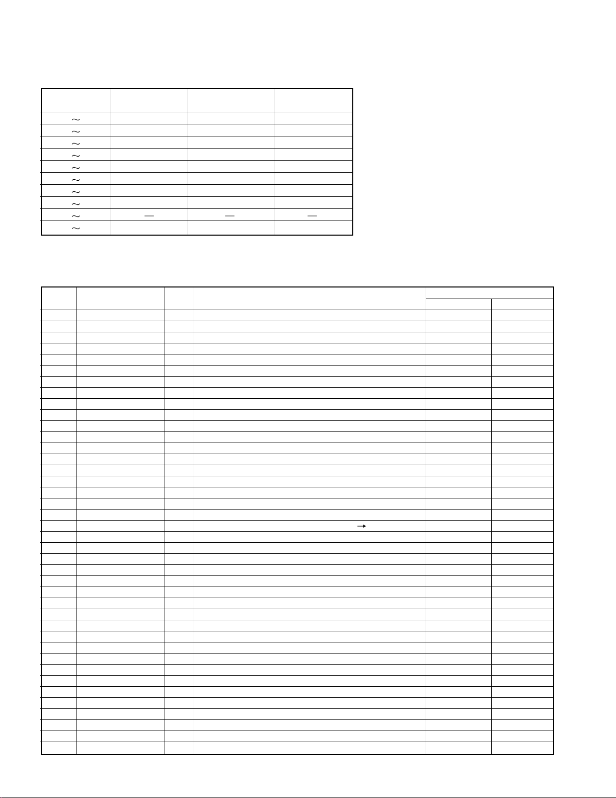
Set Type BAND
Receving Frequency
Range
Channel
Space
IF
RF
FM 87.5MHz
108.0MHz 100kHz +10. 7MHz 25kHz
K,P K1
AM 530kHz
1700 kHz 10kHz +450 kHz 10kHz
FM 87.5MHz
108.0MHz 100kHz +10. 7MHz 25kHz
M,Y K2
AM 530kHz
1610kHz 10kHz +450 kHz 10kHz
FM 87.5MHz
108. 0MHz 50kH z +10. 7MHz 25kHz
M,Y,X E1
AM 531kHz
1602kHz 9kHz +450 kHz 9kHz
FM 87. 5MHz 108.0MHz 50kHz +10.7MHz 25kHz
E,E2
E1
RDS AM 531kHz
1602kHz 9kHz +450 kHz 9kHz
FM 87. 5MHz
108. 0MHz 50kH z +10. 7MHz 25kHz
MW 531kHz
1602kHz 9kHz +450 kHz 9kHzT
E2
RDS
LW 153kHz
72 9kHz 9kHz +450kHz 9kHz
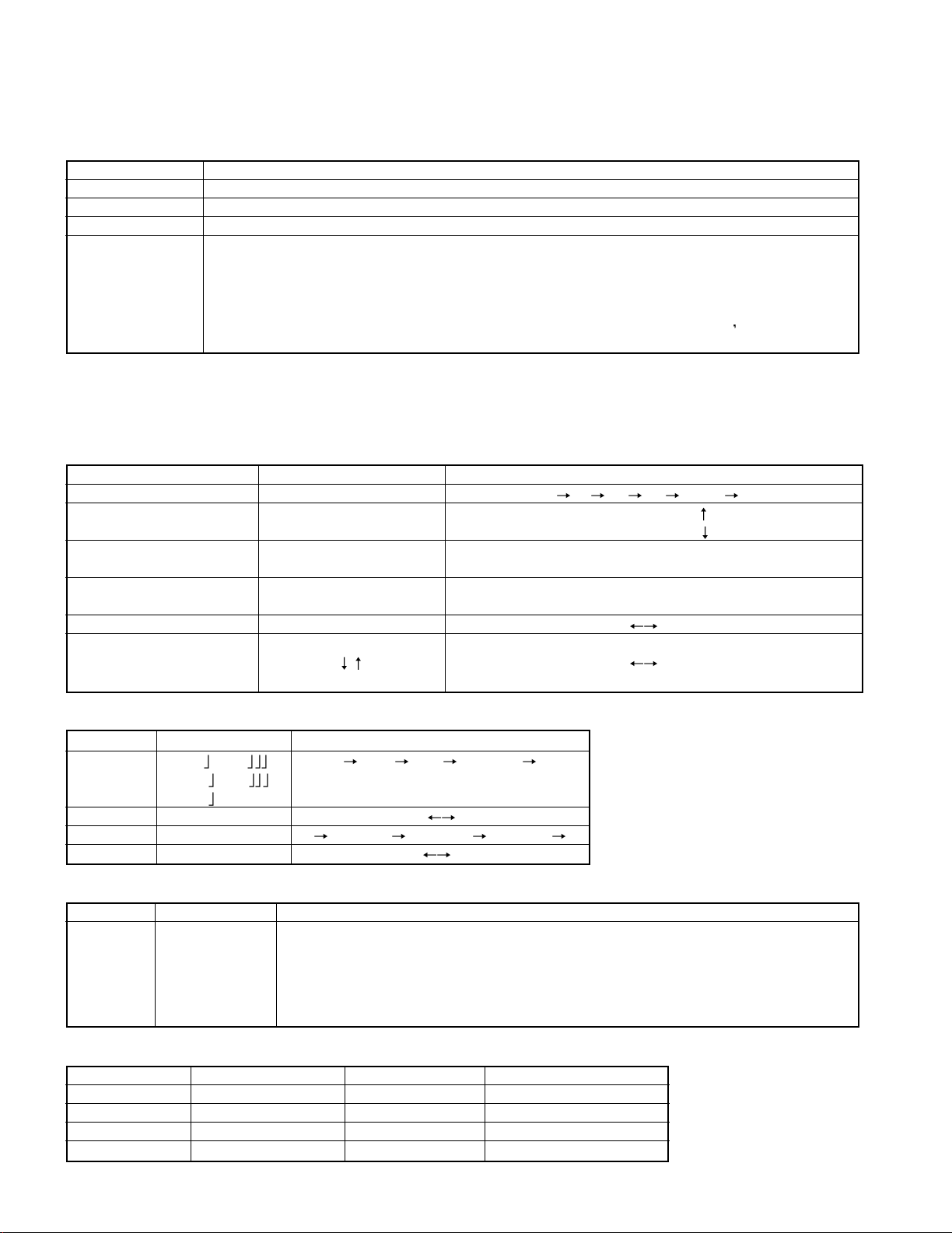
2. Destination List of Tuner
RXD-803/803E/853/853E/A83
6
CIRCUIT DESCRIPTION
AUX MODE AUX key+AC-ON
TUNER MODE TUNER(BAND) key+AC-ON
TAPE MODE TAPE A(< >) key+AC-ON
CD MODE DISC3 key+AC-ON
MENU key+AC-ON
SUB CLOCK OSC
DIAGNOSIS
The oscillation diagnosis(existence of oscillation and measurement of period) of a sub clock is per-
formed before the test mode is entered. If the diagnosis result is OK, the system enters the test mode.
If the diagnosis result is NG, the oscillation of the sub clock is diagnosed again. If the result is OK, the
system enters the test mode. If the diagnosis result is continuously NG 5 times
the system stops
with "ERR1" and "ERR2" displayed.
3. Test Mode
3-1 Setting of the Test Mode
3-2 Cancel of the test mode
By turning the power off, the system is initialized and the test mode is canceled.
3-3 Contents of the Test Mode
3-3-1 Tuner Test mode
3-3-2 Aux Test Mode
3-3-3 Deck Test Mode
KEY DISPLAY OPERATION
SELECT Normal indication 10 20 30 00 (- -)
MENU Normal indication
AUTO • STEREO
MANUAL • MONO
BACK TUNING DOWN
SOUND CONTROL
Normal indication
TUNING UP
TUNING MODE P. ch DOWN
ENTER
Normal indication
P. ch UP
DISPLAY/DEMO FL indication ON FL indication OFF
50Hz
CD OPEN/CLOSE
50Hz/50µ 100Hz/75µ
100Hz
KEY DISPLAY OPERATION
Tone
MAX MAX MIN CENTER
DISC 1 Tone MIN
Tone CENTE
DISC 2 Normal indication AUX LEVEL MAX AUX LEVEL MIN
DISC 3 Normal indication Lch MAX Rch MAX CENTER
EX.BASS Normal indication EX. BASS ON EX. BASS OFF
KEY DISPLAY OPERATION
* Mechanism SW Detection
If the REC/ARM key is pressed, the system record for 4 seconds.
Then, it rewinds to the REC starting position and plays back automatically. If the
REC/ARM key is pressed, during the 4 seconds REC operation, the system records fur-
ther for 4 seconds, then returns to the starting position of the first 4 seconds REC opera-
tion and plays back.
REC/ARM Normal display
HALF SW DISPLAY HALF SW DISPLAY
A PACK SW "T" (The first dot) A CrO2 SW "A" (The second dot)
B PACK SW "P" (The third dot) B RVS REC SW "E" (The forth dot)
B FWD SW "T" (The sixth dot) B CrO2 SW "E" (The seventh dot)
A PLAY SW "Moon" (Segment) B PLAY SW Sun(Segment)
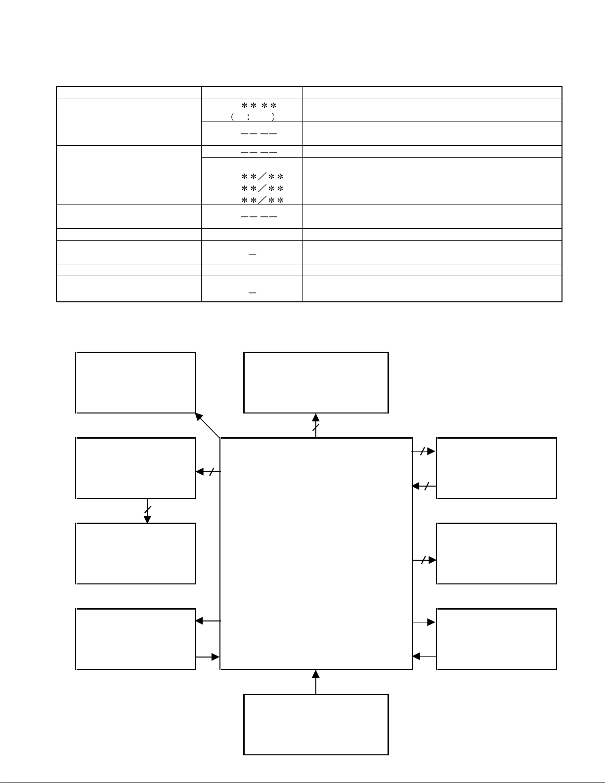
CIRCUIT DESCRIPTION
KEY DISPLAY OPERATION
CD-PLAY/PAUSE 05
:
** ** Tracking-servo on.
(Change the mode
03
: Tracking-servo off.
alternately by the stop key.)
DISC 1 01 : STOP
Adjustment value/mean value
(Cyclically changed in the 07
TB value FB value
stop mode only.) 08
TG value FG value
09 TO value FO value
STOP 01
:
Stop (Press it 1time.)
Cancel the test mode. (Press it 2 times.)
TAPE EQ Ex. 01~02 CD track no. up.
TAPE EQ
CD FF search.
(Press it more than 400msec.) The pickup travels outward.
REVERSE MODE Ex. 02~01 CD track no. down.
REVERSE MODE
CD FB search.
(Press it more than 400msec.) The pickup travels inward.
3-3-4 CD Test Mode
X28,IC1
DECK SYSTEM IC
(CXA1498S)
CD MECHA
(CDM-35)
6
X14,IC1
3
3
5
50
X14,ED1
X13,IC11
M30622MC-A70FP
2
Vaccume Fluorescent
Display
(HNA-15MM18T)
X32,IC12
TUNER PACK
DSP IC
(MN662748RPMFA)
X13,IC12
RDS IC (E, T, Q)
(BU1923F)
DECK MECHA
(CMAT2Z)
SYSREM IC
(M62498FP)
PLL IC
(LC72131)
DOT DRIVER
(LC75711NED)
4. Microprocessor : M30622MC-A70FP(X13,IC4)
4-1 Microprocessor periphery block diagram
RXD-803/803E/853/853E/A83
7
CIRCUIT DESCRIPTION
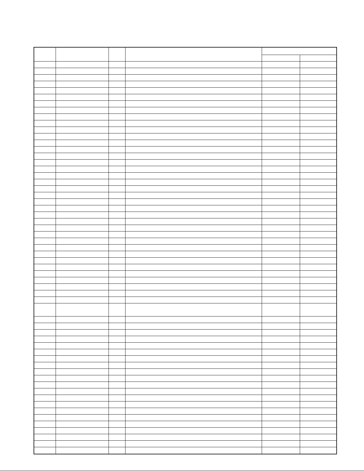
Input Voltage KEY1 KEY2 KEY3
(V) Pin97 Pin95 Pin94
0.00 0.26 POWER EX. BASS REV. MODE
0.27 0.81 DISPLAY/DEMO KEY OFF REC
0.82 1.37 TUNING MODE CD PLAY/ PAUSE TAPE EQ.
1.38 1.94 MENU BAND OPEN/CLOSE
1.95 2.51 SOUND TAPE B DISC SKIP
2.52 3.07 BACK TAPE A DISC 3
3.08 3.62 SELECT AUX DISC 2
3.63 4.16 ENTER STOP DISC 1
4.17 4.73
4.73 5.00 KEY OFF KEY OFF KEY OFF
4-2 Key Matrix
Pin No. Pin Name I/O Description
ACTIVE
HL
1 SLEVEL I RDS signal level input.
2 CE2 I Backup detection input 2. AC ON AC OFF
3 SD I SD detection input.
4 ST I Stereo detection input.
5 PLL CE O PLL IC & E. volume chip enable.
6 RDS DATA I RDS data input.
7 PLL CLK O PLL IC & E. volume clock output.
8 BYTE - GND.
9 CNVSS - GND.
10 XCIN I Timer clock input(32.768kHz).
11 XCOUT O Timer clock output(32.768kHz).
12 RST I Reset signal input. NORMAL RESET
13 X OUT O Main clock output(10MHz).
14 VSS - GND.
15 X IN I Main clock input(10MHz).
16 VCC(BU) - u-com power supply(+5.0V).
17 NMI - Connected to VCC.
18 REM I Signal input of remote control.
19 RDS CLK I RDS clock input.
20 BLKCK I Sub code synchronous signal input. L H Interrupt
21 CE I Back up detection input. AC ON AC OFF
22 BEEP SOUND O Beep sound output.
23 PLL DO I PLL IC data input.
24 CS RELAY O Relay control port for center and surround speakers. ON OFF
25 D XRESET O DSP reset port. RESET
26 DXLAT O DSP latch output.
27 AMUTE O Control port of audio muting.
28 MCLK O CD DSP command clock signal output.
29 STAT I CD DSP status signal input.
30 MDATA O CD DSP command data output.
31 FL DATA O Data output to VFD dot driver.
32 HPDET I Detection port of headphones. NORMAL H/P IN
33 FL CLK O Clock output to VFD dot driver.
34 FL CE O Chip enable output toVFD dot driver.
35 D DATA O DSP data output.
36 D READY I DSP ready signal input.
37 D.SCK O DSP clock output port.
38 SOLB O B deck solenoid control. ON OFF
39 CPM O Capstan control port for deck. ON OFF
40 SOLA O A deck solenoid control. ON OFF
4-3 Pin Description of Microprocessor
RXD-803/803E/853/853E/A83
8
9
RXD-803/803E/853/853E/A83
CIRCUIT DESCRIPTION
Pin No. Pin Name I/O Description
ACTIVE
HL
41 EX CLK15 O Clock output to expander IC(X13,IC15).
42 PS LOAD O Control port of shift/load for expander IC(X13,IC15). SHIFT LOAD
43 PS IN O Data input from expander IC(X13,IC15).
44 EX CLK16 O Clock output to expander IC(X13,IC16).
45 EX DATA O Data output to expander IC(X13,IC16).
46 ATT O -10dB attenunation output. OFF ON
47 FL RST O Reset signal output to VFD dot driver. RESET
48 LED PRO O LED output for prologic. OFF ON
49 LED 3ST O LED output for 3 stereo. OFF ON
50 LED VIR O LED output for virtual. OFF ON
51 M CONT B I Multi control jog input .
52 M CONT A I Multi control jog input .
53 VOL B I Volume encoder input .
54 VOL A I Volume encoder input .
55 LED STBY O Control port of standby LED. OFF ON
56 LED TIMER O Control port of timer LED. OFF ON
57 NC - Unused.
58 OPEN SW I CD open detection switch input.
59 CLOSE SW I CD close detection switch input.
60 TD SW I Traverse down switch input port of CD mechanism.
61 TU SW I Traverse up switch input port of CD mechanism.
62 VCC(BU) - u-com power supply(+5.0V).
63 OPEN O CD motor control output.
64 VSS - GND.
65 CLOSE O CD motor control output.
66 BRKM O CD motor control output.
67 RTL O Rotary motor opposite direction(CCW) output.
68 RTR O Rotary motor positive direction(CW) output.
69 DC OFF O Power control of CD DSP IC. ON OFF
70 CD PROT I CD protection input(Only at selector CD). NORMAL PRO. ON
71 SLT SW I CD start limit switch input.
72 MLD O CD DSP command load signal output.
73 SQCK O CD sub code clock output.
74 SUBQ I CD sub code input.
75 D MUTE O CD DSP muting output.
76 XRST O CD DSP IC reset control. RESET
77 PHTR I CD mecha. Stop switch input.
78 PS SW I
Tray position & disc detector switch input port of
CD mechanism.
79 TU ON/OFF O Tuner power on/off output.
80 REC/PLAY O Deck recording/playback control. RECORDING PLAYBACK
81 BIAS O Deck bias control. OFF ON
82 POWER O Power relay control.
83 RELAY O Control port of speaker relay.
84 EV CLK O Clock output to E..volume.
85 EV DATA O Data output to E..volume data output.
86 EMPHASIS O Tuner emphasis output.
87 EPROM DATA I/O Expander ROM data input/output.
88 EPROM CLK O Expander ROM clock output.
89 PROTECT I Detection port of protection.
90 SPEANA I Input port of music signal.
91 TYPE I Discrimination of tuner destination.
92 BPH I B deck reel sensor input.
93 APH I A deck reel sensor input.
94,95 KEY3,KEY2 I A/D key input(key3,key2).
96 AVSS - GND.
97 KEY1 I A/D key input(key1).
98 VREF - A/D reference voltage input.
99 AVCC(BU) - u-com power supply(+5.0V).
100 PLL DATA O PLL IC & E..volume data output.
RXD-803/803E/853/853E/A83
CIRCUIT DESCRIPTION
10
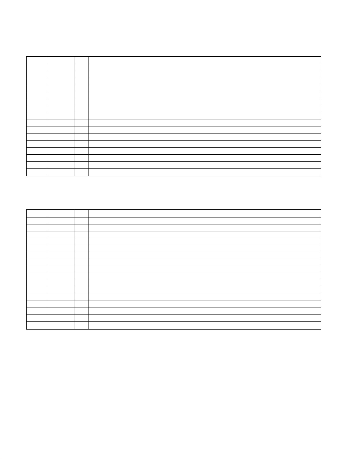
Pin No. Pin Name I/O Description
1 SI I NO USED
2 A-PLAY I A DECK Head Position Detection Switch Input H = OFF L = ON
3 B-PACK I B DECK Cassette Tape Detection Switch Input L = ON H = OFF
4 R-REC I B DECK Reverse Recording prohibition Detection Switch Input H = prohibit L = permit
5 B-PLAY I B DECK Head Position Detection Switch Input L = ON H = OFF
6 CK INH I NO USED
7 PSCLK I CLOCK INPUT
8 GND - GND
9 CLR I CONNECTED TO VDD
10 A-CrO2 I A DECK CrO2 Detection Switch Input H = CrO2 L = Normal
11 B-CrO2 I B DECK CrO2 Detection Switch Input H = CrO2 L = Normal
12 F-REC I B DECK Forward Recording prohibition Detection Switch Input H = prohibit L = permit
13 PSDATA O DATA OUTPUT
14 A-PACK I A DECK Cassette Tape Detection Switch Input L = ON H = OFF
15 PSLOAD I SHIFT/LOAD CONTROL
16 Vdd - VDD
4-4 Description of expander IC
TC74HC166AP(X13,IC15)
Pin No. Pin Name I/O Description
1 Vss - GND
2 DATA I DATA INPUT TERMINAL
3 CLK I CLOCK INPUT
4 BIAS O NC
5 NOR O DECK Normal/CrO2 Changeover Control H=Normal L=CrO2
6 B SOL O NC
7 A SOL O NC
8 CPM O NC
9 LMUTE O DECK Line Mute Control H= MUTE OFF L= MUTE ON
10 B-EQ O B DECK Play Back Equalizer Control
11 R MUTE O DECK Recording Mute Control
12 A-EQ O A DECK Play Back Equalizer Control
13 A/B O DECK A/B Changeover Control L=A DECK H=B DECK
14 R/P O NC
15 BEAT.C O DECK Beat Cancel On/Off Changeover Control H= ON L= OFF
16 Vdd - POWER SUPPLY(+5V)
BU2090F(X13,IC16)
AC 220-
240V~
AC 110-
120V~
GND
FM
75
AM
ANTENNA
+
-
FRONT
SPEAKERS
DIGITAL
OPTICAL
(
6-16
)
R
L
L
R
FRONT
+
-
SURROUND
SPEAKERS
(
12-16
)
R
L
SUPER
WOOFER
PRE OUT
CENTER
SPEAKER
(
6-16
)
OUT
CENTER
SURROUND
SUB
WOOFER
6CH.
INPUT
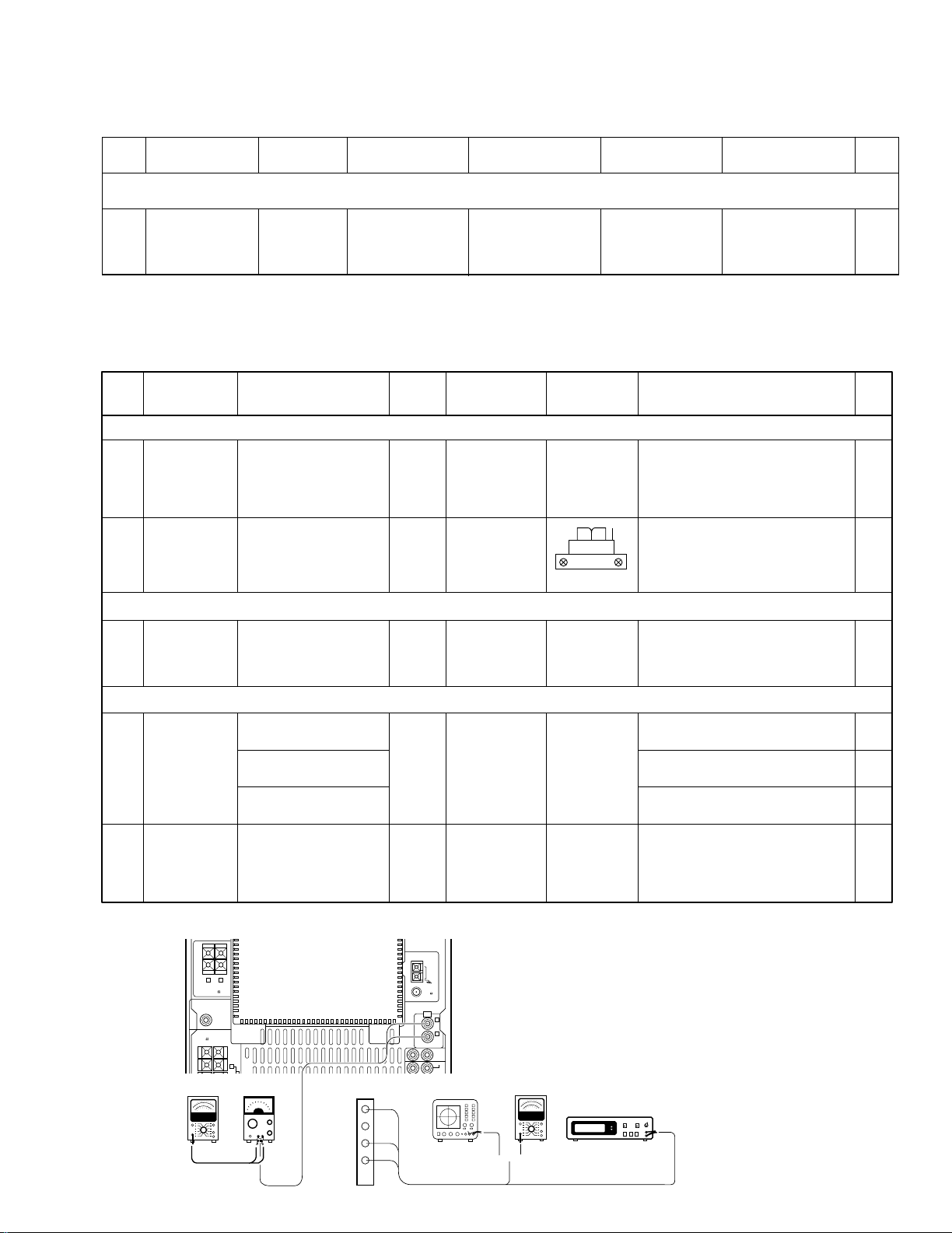
Oscilloscope
AC voltmeter
Frequency counter
AC voltmeter
AG
{
(A) (B)
X13, CN1
L-PLAY
R-PLAY
GND
28
29
30
31
RVS FWD
NO. ITEM INPUT SETTING
OUTPUT
SETTING
CASSETTE TAPE
DECK SETTING
ALIGNMENT
POINTS
ALIGN FOR FIG.
0dBs = 0.775V
I Cassette mechanism unit (Adjustment of the REC / PLAY head)
(1)
Demagnetization
and cleaning
Power : OFF
Demagnetization,
cleaning, PLAY
Recording
head, erase
head, capstan
pinch roller
Demagnetize the REC / PLAY head
with the head eraser. Clean the REC /
PLAY head, erase head, capstan and
pinch roller using a cotton swab slightly
damped with alcohol.
(2)
Azimuth of the
REC / PLAY
head
SCC-1727
TCC-153
MTT-114
10kHz, -10dB
(B) PLAY
Adjust the output to maximum and
adjust the azimuth adjustment screw
for the Lissajours waveform pattern of
the oscilloscope to become close to a
45ß straight line.
II PC BOARD ADJUSTMENT
(1)
TAPE SPEED
(NORMAL)
TCC-110
MTT-111
SCC-1727
3kHZ
(B) PLAY VR5
Adjust the tape speed so that 3kHz is
obtained at the center of the tape.
III PC board adjustment.
(1)
PLAYBACK
LEVEL
MTT-150
400Hz
(B) PLAY
VR 3 (L)
VR 4 (R)
Adjust the playback output to -2.5dBs.
MTT-256, SCC-1727
315Hz
Adjust the playback output to -5.5dBs.
MTT-256U, TCC-120
315 Hz
Adjust the playback output to -1.5dBs.
(2) BIAS CURRENT
(A)
Adjust the AG for the
output of the DECK to
become 12.5KHz -20dBs.
400Hz/12.5kHz (AC-224)
(B) REC PLAY
VR 1 (L)
VR 2 (R)
Record 400Hz and 12.5kHz alternately,
and adjust the bias current adjustment
potentiometer for the playback levels to
become the same.
11
RXD-803/803E/853/853E/A83
ADJUSTMENT
CD player adjustment
FIG.No. ITEM
INPUT
SETTINGS
OUTPUT
SETTINGS
ALIGNMENT
POINTS
ALIGN FOR
PLAYER
SETTINGS
Note:
Type 4 disc : SONY YEDS-18 Test Disc or equivalent.
LPF: Around 47 kΩ+ 390 pF or so.
Step 1~4 are in Test Mode.
1
1. While pressing the "DISC 3" key, turn the power on to enter the test mode.
2. Load a disc on disc 1 tray.
LASER CURRENT
CHECK
Test disc
Type 4
Connect the DC
voltmeter to
CN6(pin1 and 2)
on X32.
– 0.5±0.2V
Press the
PLAY/PAUSE key,
then confirm that the
display is 03 or 05.
Measurement Equipment Connections
Cassette Deck adjustment
Loading...