


 Loading...
LBH-1790AN,1795AN INSTRUCTION MANUAL
CONTENTS
I. IMPORTANT SAFETY INSTRUCTIONS...................................................... |
1 |
||
II. SPECIFICATIONS....................................................................................... |
1 |
||
1. |
Specifications......................................................................................................................... |
2 |
|
2. |
Standard sewing shape list................................................................................................... |
3 |
|
3. |
Configuration.......................................................................................................................... |
4 |
|
III. INSTALLATION.......................................................................................... |
5 |
||
IV. PREPARATION BEFORE OPERATION.................................................. |
15 |
||
1. |
Lubrication............................................................................................................................ |
15 |
|
2. |
Inserting the needle.............................................................................................................. |
16 |
|
3. |
Threading the needle-thread............................................................................................... |
17 |
|
4. |
Threading the bobbin case.................................................................................................. |
17 |
|
5. Adjusting the bobbin thread tension.................................................................................. |
18 |
||
6. |
Installation of bobbin case.................................................................................................. |
18 |
|
7. |
Installing the knife................................................................................................................ |
19 |
|
8. |
Checking the sewing machine in the delivered state....................................................... |
19 |
|
V. OPERATION OF THE SEWING MACHINE.............................................. |
20 |
||
1. |
Explanation of the operation panel switch........................................................................ |
20 |
|
2. |
Basic operation of the sewing machine............................................................................. |
22 |
|
3. |
How to use the pedal............................................................................................................ |
24 |
|
4. |
Input of the presser type...................................................................................................... |
26 |
|
5. |
Performing pattern selection............................................................................................... |
27 |
|
6. |
Changing needle thread tension......................................................................................... |
28 |
|
7. |
Performing re-sewing........................................................................................................... |
29 |
|
8. |
Winding bobbin thread........................................................................................................ |
30 |
|
9. |
Using the counter................................................................................................................. |
31 |
|
10. |
Using the initial value pattern........................................................................................... |
33 |
|
11. Changing sewing data........................................................................................................ |
34 |
||
12. |
Method of setting sewing data with/without edit............................................................. |
36 |
|
13. |
Sewing data list.................................................................................................................. |
37 |
|
14. |
Copying sewing pattern..................................................................................................... |
43 |
|
15. |
How to edit/check the data other than sewing data........................................................ |
44 |
|
16. |
Using parameter register key............................................................................................ |
46 |
|
17. |
Performing continuous stitching...................................................................................... |
47 |
|
18. |
Performing cycle stitching................................................................................................ |
50 |
|
19. |
How to change the name of cycle/continuous sewing data........................................... |
52 |
|
20. |
Explanation of plural motions of knife............................................................................. |
53 |
|
21. |
Method of changing memory switch data........................................................................ |
54 |
|
22. |
Memory switch data list..................................................................................................... |
55 |
|
23. How to change the sewing speed while the sewing machine is engaged in sewing.......... |
59 |
||
24. |
How to adjust the pedal variable resistor........................................................................ |
60 |
|
i
25. How to adjust the contrast................................................................................................ |
61 |
|
26. How to set the key lock...................................................................................................... |
61 |
|
27. Communication.................................................................................................................. |
62 |
|
28. Setting the irregular work.................................................................................................. |
66 |
|
VI. MAINTENANCE....................................................................................... |
68 |
|
1. Adjusting the needle-to-hook relation................................................................................ |
68 |
|
2. Adjusting the needle thread trimmer.................................................................................. |
69 |
|
3. Adjusting the presser bar pressure.................................................................................... |
70 |
|
4. Adjustment of the bobbin presser unit............................................................................... |
70 |
|
5. |
Thread tension...................................................................................................................... |
71 |
6. |
Replacing the fuse................................................................................................................ |
72 |
VII. GAUGE COMPONENTS......................................................................... |
73 |
|
1. |
Cloth cutting knife................................................................................................................ |
73 |
2. |
Throat plate........................................................................................................................... |
73 |
3. |
Presser.................................................................................................................................. |
73 |
VIII. ERROR CODE LIST............................................................................... |
74 |
|
1. |
How to operate the sewing machine in the case an error is displayed........................... |
74 |
2. |
Operation procedure to be followed when a message is displayed................................ |
80 |
IX. TROUBLES AND CORRECTIVE MEASURES....................................... |
81 |
|
X. DRAWING OF THE TABLE...................................................................... |
83 |
|
XI. INITIAL VALUE DATA FOR EACH SHAPE TABLE................................ |
85 |
|
ii

I.IMPORTANT SAFETY INSTRUCTIONS
1)Never operate the machine unless the oiling tank has been properly lubricated.
2)After the completion of a day's work, remove dust and dirt accumulating on the hook, bobbin thread trimming knife section and lubricating hole of the oil tank. At this time, also check whether or not the oil quantity is adequate.
3)Be sure to return the starting pedal to the home position after the machine has started to run.
4)This machine is provided with a machine head tilt detector so that it cannot be operated in the state that the machine head is tilted. When operating this sewing machine, turn the power switch ON after setting the sewing machine to the bed base properly.
II. SPECIFICATIONS
Main specifications of the LBH-1790AN, LBH-1795AN computer-controlled, lockstitch buttonholing machine.
Subclass |
|
|
|
|
S |
|
|
|
|
|
|
Major application |
Buttonholing of cloth such as men’s shirts, blouses, |
||||
|
work uniforms, ladies' wear, etc. |
||||
Buttonholing size |
|
|
|
|
Standard : Max. 5 mm |
|
|
|
|
|
Special type part : Max. 10 mm |
|
|
|
|
|
|
|
|
|
|
|
Knife size used : |
|
|
|
|
||
|
|
|
|
|
6.4 to 31.8 mm (1/4' to 1-1/4') |
|
|
|
|
|
Buttonholing sewing length |
|
|
|
|
|
|
|
|
|
|
|
Standard : Max. 41 mm |
|
|
|
|
|
Special type part : Max. 120 mm |
|
|
|
|
|
|
– 1 –

1. Specifications
Sewing speed |
Standard speed : 3,600 sti/min (Max. : 4,200 sti/min) (Max. : 3,300 sti/ |
|
min when dry hook is used) |
|
|
Needle |
DP × 5 #11J to #14J |
|
|
Hook |
DP type full-rotary hook |
|
|
Needle rocking drive method |
Drive by stepping motor |
|
|
Feed drive method |
Drive by stepping motor |
|
|
Presser lifting drive method |
Drive by stepping motor |
|
|
Lift of presser foot |
14 mm (Optional setting available) Max. : 17 mm (At the time of nee- |
|
dle up by reverse run) |
|
|
Cloth cutting knife drive method |
Motor-driven crank system |
|
|
Standard sewing shape |
31 kinds |
|
|
Number of patterns stored in |
99 patterns |
memory |
|
|
|
Mass |
Machine head 55 kg, Control box 5.5 kg |
|
|
Power consumption |
370 VA |
|
|
Operating temperature range |
5 ˚C to 35 ˚C |
|
|
Operating humidity range |
35% to 85% (No dew condensation) |
|
|
Line voltage |
Rated voltage ± 10% 50/60 Hz |
|
|
Motor used |
3-phase 200 to 240 V, 370 VA |
|
|
Noise |
- Equivalent continuous emission sound pressure level (LpA) at the |
|
workstation : |
|
A-weighted value of 81.0 dB ; (Includes ; KpA = 2.5 dB) ; according |
|
to ISO 10821- C.6.3 -ISO 11204 GR2 at 3,600 sti/min. |
|
|
– 2 –

2. Standard sewing shape list
(1) Square type |
(2) Round type |
|
(3) Radial square |
(4) Radial type |
(5) Radial straight |
(6) Radial taper |
(7) Eyelet square |
|||
|
|
|
type |
bar-tacking type |
bar-tacking type |
type |
||||
|
|
|
|
|
|
|
|
|
|
|
PANEL |
PANEL |
|
|
|
PANEL |
|
PANEL |
PANEL |
PANEL |
PANEL |
DISPLAY |
DISPLAY |
|
|
|
DISPLAY |
|
DISPLAY |
DISPLAY |
DISPLAY |
DISPLAY |
|
|
|
|
|
|
|
|
|
|
|
(8) Eyelet radial |
(9) Eyelet straight |
|
(10) Eyelet taper |
(11) Semilunar |
(12) Round |
(13) Semilunar |
(14) Semilunar |
|||
|
straight bar-tack- |
|||||||||
type |
bar-tacking type |
|
|
bar-tacking type |
|
type |
square type |
square type |
ing type |
|
|
|
|
|
|
|
|
|
|
|
|
PANEL |
PANEL |
|
|
|
PANEL |
|
PANEL |
PANEL |
PANEL |
PANEL |
DISPLAY |
DISPLAY |
|
|
|
DISPLAY |
|
DISPLAY |
DISPLAY |
DISPLAY |
DISPLAY |
|
|
|
|
|
|
|
|
|
|
|
(15) Semilunar |
(16) Eyelet semi- |
|
(17) Eyelet round |
(18) Square radi- |
(19) Square |
(20) Square |
(21) Square |
|||
taper bar-tacking |
|
straight bar-tack- |
||||||||
type |
lunar type |
|
|
|
type |
|
al type |
semilunar type |
round type |
ing type |
|
|
|
|
|
|
|
|
|
||
PANEL |
PANEL |
|
|
|
PANEL |
|
PANEL |
PANEL |
PANEL |
PANEL |
DISPLAY |
DISPLAY |
|
|
|
DISPLAY |
|
DISPLAY |
DISPLAY |
DISPLAY |
DISPLAY |
|
|
|
|
|
|
|
|
|||
(22) Square taper |
(23) Radial semi- |
|
(24) Radial round |
(25) Semilunar |
(26) Semilunar |
(27) Bar-tacking |
(28) Bar-tacking, |
|||
bar-tacking type |
lunar type |
|
|
|
type |
|
radial type |
round type |
|
right cut |
PANEL |
PANEL |
|
|
|
PANEL |
|
PANEL |
PANEL |
PANEL |
PANEL |
DISPLAY |
DISPLAY |
|
|
|
DISPLAY |
|
DISPLAY |
DISPLAY |
DISPLAY |
DISPLAY |
|
|
|
|
|
|
|
|
|
|
|
(29) Bar-tacking, |
(30) Bar-tacking, |
|
|
(31) Basting + Cloth |
|
|
|
|
||
left cut |
center cut |
|
|
cutting knife |
|
|
|
|
|
|
|
|
|
|
|
|
|
|
|
|
|
PANEL |
PANEL |
|
|
PANEL |
|
|
|
|
||
DISPLAY |
DISPLAY |
|
DISPLAY |
|
|
|
|
|||
|
|
|
|
|
|
|
|
|
|
|
– 3 –

3. Configuration
|
|
|


LBH-1790AN, LBH-1795AN consists of the following components.
Power switch
Machine head (LBH-1790AN, LBH-1795AN)
Operation panel
Control box (MC-602)
Presser lifting and starting pedal
Thread stand device
Power switch (EU type)
– 4 –

III. INSTALLATION
WARNING :
To prevent possible accidents caused by the fall of the sewing machine, perform the work by two persons or more when the machine is moved.
(1)Preparation for assembly of the control box
1)Fix toothed washers and rubber cushions on control box . (At four
locations)
* Tighten the toothed washers so that their height becomes 0.8 mm.
2) Fix control box mounting plate with plain washers and nuts . (At four locations)
* Fix the mounting plate while fitting the screw in the U-groove in the mounting plate.
❺

0.8 mm


At four locations
– 5 –

(2) Set-up of the table


1)Fix control box , power switch and pedal sensor on table .
2)Fix power switch with a staple.
3)Pass four bed base fixed screws through bed base .
4)Set rubber cushions to holes (4 places) for fixing bed base and fix bed base .
5)Fix head support bar on table .
6)Place the main unit of the sewing machine on bed base . Then, connect the pedal and pedal sensor with connecting rod supplied with the unit.
– 6 –
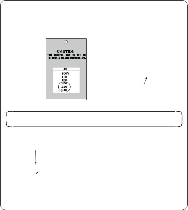
(3) Connecting the power source cord
• Connecting the power cable
Voltage specifications are shown on the power indication tag attached on the power cable and on the rating plate adhered on the power box. Connect the cable which matches the specifications.
Power indication tag
Rating plate
(For example: In the case of 200V)

 Never use under the wrong voltage and phase.
• Connecting three phase 200V, 220V and 240V
White White
|
White |
|
|
|
AC200 V |
|||
|
|
|
|
|||||
|
Black |
|
|
|
|
|||
Control |
|
|
|
AC220 V |
||||
|
|
|
||||||
|
Red |
|
|
|
|
|
AC240 V |
|
|
|
|
|
|
|
|
||
|
Green / |
|
|
|
GND |
|||
Black Red |
Yellow |
|
|
|
|
|||
Power switch |
Power source cord |
|
|
|
|
|||
– 7 –
(4) Installing the sewing machine main unit
WARNING :
To prevent possible accidents caused by the fall of the sewing machine, perform the work by two persons or more when the machine is moved.
hinge plates and shaft bearings -1 (rubber) and -2 (metal) in two places on the base and fix the hinge plates to the ma-
head with setscrews in two places.
When the rubber hinge and metal fitting hinge are installed in reverse order, it is dangerous since the sewing machine shakes when it is tilted. So, be careful.
-1 (rubber)
|
|
|
-2 |
|
(metal) |
(5) Tilting the sewing machine head
WARNING :
When tilting/raising the sewing machine head, perform the work so as not to allow your fingers to be caught in the machine. In addition, to avoid possible accidents caused by abrupt start of the machine, turn OFF the power to the machine before starting the work.
When tilting the sewing machine head, tilt quietly the sewing machine until head support bar comes in contact with it.
1. Make sure that sewing machine head support bar is placed on the table before tilting the sewing machine.
2. To protect fall-down, be sure to tilt the sewing machine in a level place.
– 8 –
(6) Connecting the machine head tilt detector
Connect machine head tilt detector with connector located on the machine head
side.
(7) Installing the hook oil shield plate


Install hook oil shield plate onto bed base with setscrew .
Attach hook oil shield plate to the bed base with the sewing machine raised.
In addition, check to be sure that the sewing machine does not interfere with hook oil shield plate when tilting/raising the former.
Adjust the mounting of the hook oil shield plate to prevent scattered from the gap between the bed and cover pot.
(8) Installing the operation panel
Fix operation panel on the table with four woodscrews . Pass the cable through hole in the
|
|
table. |
|

– 9 –

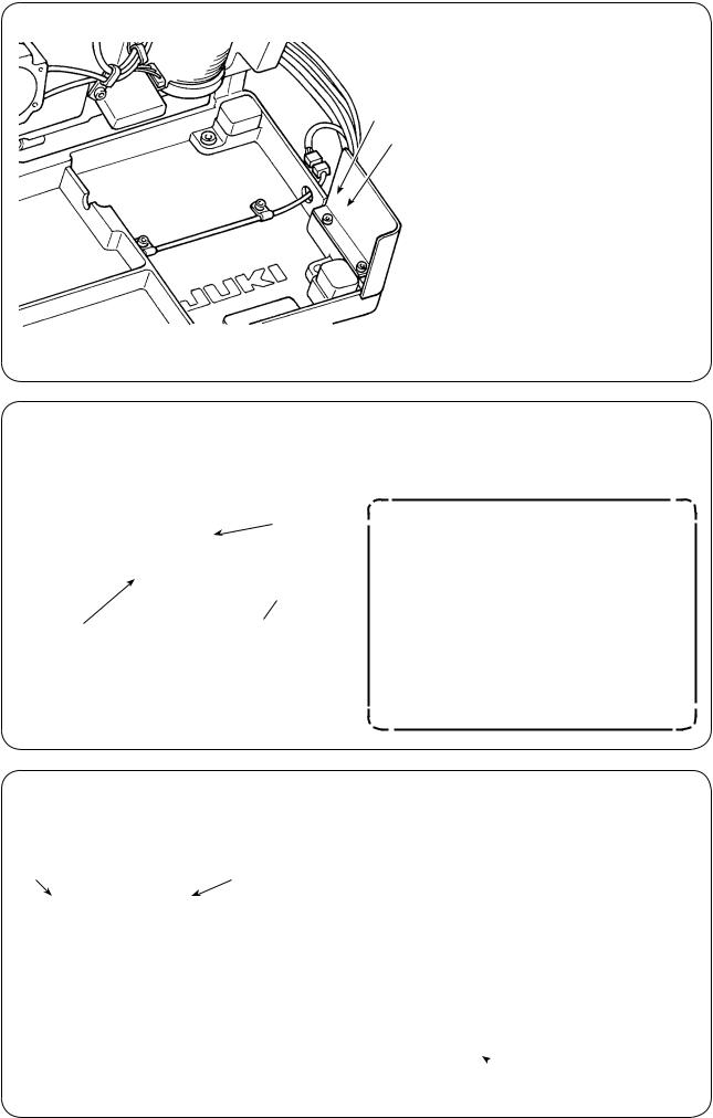
(9) Connecting the cords

1)Loosen four setscrews of control box cover . Remove control box cover .
2)Connect the cord to the connector on the MAIN PCB as illustrated in the figure below.
3)Fix the earth cord with setscrew .
4)Install control box cover .
5)Fix control box cover with the washers, spring washers and nuts .
Earth cord
CN15
CN17
CN32
CN40
CN49
CN39
CN34
CN44
MAIN circuit board
Sewing machine head
Operation panel
Electric bobbin winding device (optional)
CN32
MAIN-INT B
CN39
CN40 Pedal
MAIN-INT C
CN34
Panel CN49
MAIN-INT A
encoder
CN17 |
|
|
|
Main motor cord |
|
Earth cord
– 10 –

(10) Managing the cord
1) Slowly tilting the sewing machine, check that the cords are not forcibly pulled.
When you tilt the sewing machine, make sure that the sewing machine head support bar is
placed on the table.
2)Bring the cords under the table into the control box.
3) Put the cord brought into the control box
through cord exit plate and fix cable clip band .
|
4) Install control box lid |
with four set- |
screws . |
|
|
|
|

– 11 –

(11) Installing the eye protection cover
WARNING :
Be sure to attach this cover to protect the eyes from the disperse of needle breakage.
Be sure to install and use eye protection cover and use the sewing machine.
When placed longitudinally |
When placed horizontally |
Operator
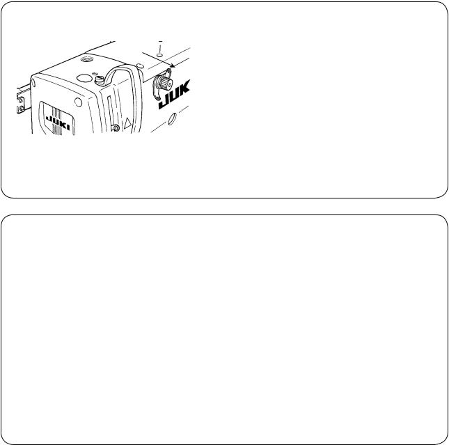
(12) Fixing the temporary stop switch
The temporary stop switch has been in the state as shown in figure A at the time of delivery.
Loosen setscrew and set the switch in the state as shown in figure B, and fix it with setscrew together with setscrew supplied with the machine.
|
|
|
B
A
– 12 –
(13) Thread guide rod
Securely fit the thread guide rod so that two side holes in the thread guide rod face the thread guide.
(14) Installing the thread stand
1) Assemble the thread stand, and set it in the hole in the top right corner of the machine table.
2) Tighten locknut to fix the thread stand.
– 13 –

(15) Installing the auxiliary table
1) Temporarily fix two auxiliary table mounting plates on auxiliary table with four bolts .
2) Temporarily fix auxiliary table on the
sewing machine bed with two bolts .
|
3) |
Fix four bolts while removing a clear- |
|
|
|
ance between the sewing machine bed |
|
|
|
and auxiliary table . |
|
|
4) |
Fix two bolts while aligning auxiliary |
|
|
|
table with the top surface of the sewing |
|
|
machine bed. |
||
|
|||
|
– 14 –

IV. PREPARATION BEFORE OPERATION
1. Lubrication
WARNING :
To protect against possible personal injury due to abrupt start of the machine, be sure to start the following work after turning the power off and ascertaining that the motor is at rest.
Front side |
|
Front |
side |
1)Lubricating oil to oiling tank
○Fill the oiling tank with JUKI New Defrix Oil No.1 up to the level indicated by “MAX” .
(Caution) When supplying oil to the oil tank through the lubricating hole, take care not to allow dust to enter the oil tank.
○Supply oil in the case the oil cannot be visually observed from the front side of the oil tank.
Detailed diagram of oil amount adjusting section
Oil pipe
Oil amount
Increase Decrease
Decrease
Increase
2)Adjusting the lubrication for the sewing hook
○The amount of oil is adjusted with oil amount adjusting screw .
○Amount of supplied oil is reduced when turning the screws clockwise.
○When you first operate your sewing machine after set-up or after an extended period of disuse, re-
move the bobbin case and apply a few drops of oil to the hook race. In addition, apply a few drops oil from oiling hole in hook driving shaft front metal to soak the inside felt in oil.
–15 –

|
|
3) How to check the hook oil quantity |
|
|
|
1. In preparation for checking the hook oil quan- |
|
mm |
|
tity, cut a sheet of paper to make a piece of |
|
|
paper size of which is approximately 40 mm x |
||
100 |
|
100 mm. |
|
|
|
||
|
|
2. After the adjustment of the oil quantity, start |
|
40 mm |
|
the sewing machine at a high speed (3,600 |
|
|
sti/min) by 100 times or more. |
||
|
|
||
|
|
3. Insert the piece of paper prepared in Step 1 |
|
|
|
into the clearance provided between the hook |
|
|
|
cover and the bed base so that it is placed |
|
|
|
near the underside of the hook. |
|
|
|
As a guide, insert the paper until it comes in |
|
|
2 to 5 mm |
contact with the hook oil shield. |
|
|
4. Supporting the paper with hand, run the sew- |
||
* The adequate oil quantity is achieved when the |
|||
ing machine by five cycles using the standard |
|||
oil spots are made on paper within a range of 2 to |
pattern (3,600 sti/min) and check the splash- |
||
5 mm in width (oil spots should not be in the form |
|||
ing oil quantity. |
|||
of lines). |
|
||
|
Approximately |
In the case the oil quantity is too much |
|
0.5 mm |
|||
even after the oil controlling screw is |
|||
|
|
||
Approximately |
|
fully tightened, remove the hook shaft |
|
0.5 mm |
|
coupling and cut off the excess of |
|
|
|
oil wick . |
|
|
|
|
|
2. Inserting the needle
WARNING :
To protect against possible personal injury due to abrupt start of the machine, be sure to start the following work after turning the power off and ascertaining that the motor is at rest.
Hold needle with its recessed part facing toward the operator side A, insert the needle fully into the needle clamping hole, and tighten needle setscrew . Use a DPx5-(#11J, #14J).
|
When attaching the needle, turn OFF the power to the |
|
|
|
motor. |
|
A |
– 16 –

3. Threading the needle-thread
WARNING :
To protect against possible personal injury due to abrupt start of the machine, be sure to start the following work after turning the power off and ascertaining that the motor is at rest.
Cotton thread, spun thread Synthetic filament thread
Pass the needle thread in the order to as shown in the figures.
The threading can be done easily by using the needle threader supplied with the machine. Change the thread guide threading method according to the thread to be used.
4. Threading the bobbin case
Purl stitch |
Whip stitch |
|
|
Bobbin |
Bobbin case |
Rotating direction of bobbin and threading
1)Fit the bobbin so that it rotates in the direction of the arrow.
2)Pass the thread through thread slit , then through under the tension spring , again through thread slit , and pull the thread from .
3)Threading at for purl stitching is different from that for whip stitching. So, be careful.
–17 –
5. Adjusting the bobbin thread tension
Adjust the bobbin thread tension as given below when the bobbin thread is pulled up at the position where thread slit of bobbin case comes up.
Purl stitch |
0.05 to 0.15N |
To such an extent that bobbin case quietly comes down when holding |
|
thread end coming from bobbin case and shaking it quietly up and down. |
|||
|
|
||
|
|
|
|
Whip stitch |
0.15 to 0.3N |
To such an extent that bobbin case barely comes down when holding |
|
thread end coming from bobbin case and shaking it somewhat strongly. |
|||
|
|
||
|
|
|
Turning tension adjust screw clockwise will increase bobbin thread tension, and turning it counterclockwise will decrease the tension.
Adjust the bobbin thread tension to lower for synthetic filament thread, and to higher for spun thread. The thread tension is higher by approximately 0.05N when the bobbin case is set to the hook since idle-pre- vention spring is provided.
When bobbin thread tension is adjusted, check the needle thread tension setting of the memory switch. (Refer to "V-22. Memory switch data list" p.55.)
6. Installation of bobbin case
WARNING :
To protect against possible personal injury due to abrupt start of the machine, be sure to start the following work after turning the power off and ascertaining that the motor is at rest.
|
1) Lift up and hold bobbin case latch lever between |
|
|
|
two fingers. |
|
2) Push the bobbin case into the hook so that it is |
|
supported by the hook shaft and then snap in |
|
the latch lever. |
|
Press the bobbin case until the predetermined |
|
position is reached, and it will click. |
|
1. If the bobbin case is out of the pre- |
|
|
|
determined position, it can jump out |
|
|
|
from the hook to cause the needle |
|
thread to tangle on the hook shaft. |
|
Check to be sure that the bobbin |
|
case is properly installed in the cor- |
|
rect position. |
|
2. There is a difference in the shape of |
|
bobbin case between the standard |
|
hook and the dry one. They have |
|
nothing in common with each other. |
– 18 –

7. Installing the knife
WARNING :
To protect against possible personal injury due to abrupt start of the machine, be sure to start the following work after turning the power off and ascertaining that the motor is at rest.
|
|
|
1 to 2 mm |
|
|
|
|
|
|||
Inch → mm CONVERSION TABLE |
|||
|
|
|
|
Knife size |
|
Indication of mm |
|
1/4 |
|
6.40 |
|
3/8 |
|
9.50 |
|
7/16 |
|
11.10 |
|
1/2 |
|
12.70 |
|
9/16 |
|
14.30 |
|
5/8 |
|
15.90 |
|
11/16 |
|
17.50 |
|
3/4 |
|
19.10 |
|
13/16 |
|
20.60 |
|
7/8 |
|
22.20 |
|
|
1 |
|
25.40 |
1 |
1/8 |
|
28.60 |
1 |
1/4 |
|
31.80 |
1 |
3/8 |
|
34.90 |
1 |
1/2 |
|
38.10 |
When replacing the knife with a new one, perform as follows.
1)Knife can be easily removed together with the washer when removing knife retaining screw .
2)Lower the knife bar by hand. Now, push the knife bar down so that the knife goes below the top surface of the throat plate by 1 to 2 mm, as illustrated in the figure. In this state, place the washer and tighten the setscrew.
When the cloth cutting knife you have is indicated in inch, set the cloth cutting length (knife size) in mm using the inch → mm conversion table. (Refer to "V-
13. Sewing data list" p.37.)
8. Checking the sewing machine in the delivered state
If the work clamp foot is the lifted state before turning the power ON, lower it firstly and turn ON the power to the sewing machine.
When lowering the work clamp, take care not to place your hands near the knife.
If the power is turned ON with the work clamp raised and the ready key is pressed, "E998 Work clamp deviation error" can occur.
– 19 –

V. OPERATION OF THE SEWING MACHINE
1. Explanation of the operation panel switch
|
|
|
|
|
|
|
|
|
|
|
|
|
|
|
|
|
|
|
|
|
|
|
|
|
|
|
|
|
|
|
|
|
|
|
|
|
|
|
|
|
|
|
|
|
|
|
|
|
|
– 20 –
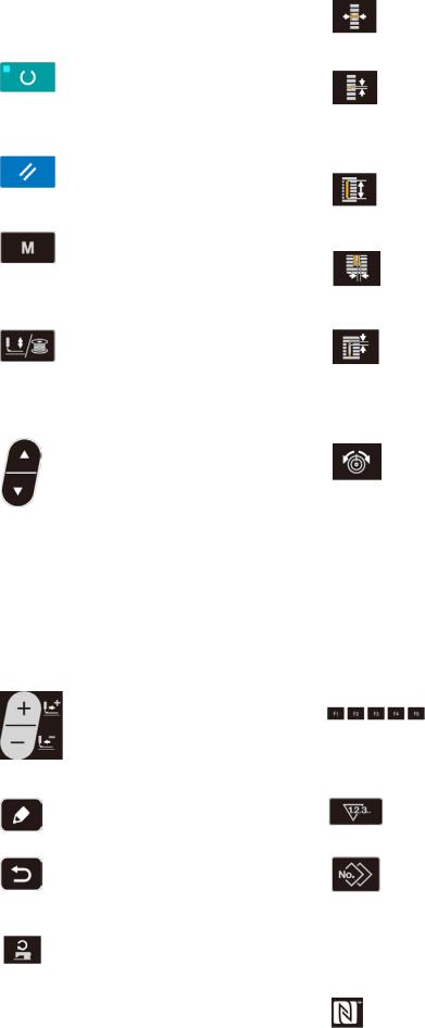
No. |
NAME |
FUNCTION |
No. |
NAME |
FUNCTION |
|
LCD display |
Various data such as pattern |
|
OVEREDGING |
This key selects overedging width |
|
|
No., shape, etc. are displayed. |
|
WIDTH key |
display. |
|
|
|
|
|
Every time this key is pressed, |
|
|
|
|
|
S005 and S006 are displayed alter- |
|
|
|
|
|
nately. |
|
READY key |
Press this key when starting |
|
PITCH key |
This key selects pitch of parallel |
|
|
sewing. |
|
|
section. |
|
|
Every time this key is pressed, |
|
|
Every time this key is pressed, |
|
|
change-over of sewing ready |
|
|
S007 and S021 are displayed alter- |
|
|
set state and data set state can |
|
|
nately. |
|
|
be performed. |
|
|
|
|
RESET key |
Press this key when releasing |
|
CLOTH CUT |
This key selects cloth cut length |
|
|
error, travelling the feed mech- |
|
LENGTH key |
display. |
|
|
anism to its initial position, |
|
|
|
|
|
counter resetting, etc. |
|
|
|
|
|
|
|
|
|
|
MODE key |
This key is used for displaying |
|
KNIFE GROOVE |
This key is used to select the knife- |
|
|
the mode screen. |
|
WIDTH key |
groove width correction display. |
|
|
|
|
|
Every time this key is pressed, |
|
|
|
|
|
S003 (right) and S004 (left) are |
|
|
|
|
|
displayed alternately. |
|
PRESSER and |
This key lifts or lowers the press- |
|
CLEARANCE |
This key selects clearance display. |
|
WINDER key |
er. When the presser goes up, |
|
key |
Every time this key is pressed, |
|
|
the needle bar travels to the ori- |
|
|
S022 (first clearance) and S023 |
|
|
gin and when it comes down, the |
|
|
(second clearance) are displayed |
|
|
needle bar travels to the right. |
|
|
alternately. |
|
|
This key is pressed when per- |
|
|
|
|
|
forming bobbin winding. |
|
|
|
|
ITEM SE- |
This key is used to select the |
|
THREAD TEN- |
This key is used to select the |
|
LECT key |
data No. and other kinds of |
|
SION key |
thread tension display. |
|
|
data. |
|
|
Every time this key is pressed, the |
|
|
|
|
|
display item is changed over as |
|
|
|
|
|
described below: |
|
|
|
|
|
S052Thread tension at the right |
|
|
|
|
|
parallel section |
|
|
|
|
|
S053Thread tension at the left |
|
|
|
|
|
parallel section (first cycle of |
|
|
|
|
|
double stitching) |
|
|
|
|
|
S054Thread tension at the right |
|
|
|
|
|
parallel section (first cycle of |
|
|
|
|
|
double stitching) |
|
|
|
|
|
S055Thread tension at the first |
|
|
|
|
|
bartacking section |
|
|
|
|
|
S056Thread tension at the second |
|
|
|
|
|
bartacking section |
|
DATA |
This key is used to change the |
|
PARAMETER |
This is a short cut key that parame- |
|
CHANGE key |
pattern No. and other kinds of |
|
REGISTRATION |
ter registration is available. Regis- |
|
|
data. |
|
key |
tration of shortcut to setting display |
|
|
This key is used to move the |
|
|
of an optional pattern, sewing |
|
|
feed forward on a stitch-by- |
|
|
parameter or adjustment data is |
|
|
stitch basis. |
|
|
possible. For the setting procedure, |
|
|
|
|
|
Refer to "V-16. Using parameter |
|
|
|
|
|
register key" p.46. |
|
EDIT key |
This key is used to display the |
|
COUNTER key |
This key selects counter display. |
|
|
edit screen, to select the item |
|
|
|
|
|
or to display the detail screen. |
|
|
|
|
|
|
|
|
|
|
RETURN key |
This key is used to return the |
|
COPY key |
Press this key when copying pat- |
|
|
screen to the previous one. |
|
|
tern. |
|
|
|
|
|
|
|
SEWING |
This key is used to display the |
|
SET READY |
It lights up under the sewing mode. |
|
SPEED key |
parameter edit items related to |
|
LED |
|
|
|
the sewing speed. |
|
|
|
|
|
|
|
|
|
|
|
|
|
NFC mark |
Bring the tablet or smartphone |
|
|
|
|
|
close to the NFC mark when |
|
|
|
|
|
carrying out communication. |
|
|
|
|
|
|
– 21 –

2. Basic operation of the sewing machine
1) Select the model of your sewing machine. |
A |
When you turn the power ON for the first time after the purchase of your sewing machine, the model confirmation screen is displayed. Press
READY key  .
.
B
When Error E001 screen B is displayed, turn the power OFF.
C
* In the case the power-OFF screen C is displayed after the completion of procedure de - scribed in 1), turn the power OFF once. Then, carry out the procedure described 1) again.
– 22 –

2) Turn ON the power switch. |
A |
When you turn ON the power to the sewing machine for the first time after the purchase, the language selection screen A is displayed. Select the language to be displayed, then press return
key  .
.
If you terminate the language selection by pressing return key 
without selecting the language, the language selection screen will be
displayed every time you turn ON the power to the sewing machine.
First, check that presser type B which has been set is the same as that of the presser actually mounted. For checking and setting procedures, refer to "V-4. Input of the presser type" p.26.
3)Select the pattern No. you desire to sew.
When the power is turned ON, the pattern No. C and pattern data name D are displayed.
When you want to change the pattern number,
press DATA CHANGE key |
and select |
the number you want to use for sewing.
When you purchase the sewing machine, pattern No. 1 to 10 described in "V-11. Changing sewing data" p.34 have been registered. Select the pattern No. you sesire to sew from among these numbers. (The No. with which the pattern has not been registered is not displayed.)
B C |
|
D |
|
|
|
||||||||||||||||||||||||
|
|
|
|
|
|
|
|
|
|
|
|
|
|
|
|
|
|
|
|
|
|
|
|
|
|
|
|
|
|
|
|
|
|
|
|
|
|
|
|
|
|
|
|
|
|
|
|
|
|
|
|
|
|
|
|
|
|
|
|
|
|
|
|
|
|
|
|
|
|
|
|
|
|
|
|
|
|
|
|
|
|
|
|
|
|
|
|
|
|
|
|
|
|
|
|
|
|
|
|
|
|
|
|
|
|
|
|
|
|
|
|
|
|
|
|
|
|
|
|
|
|
|
|
|
|
|
|
|
|
|
|
|
|
|
|
|
|
|
|
|
|
|
|
|
|
|
|
|
|
|
|
|
|
|
|
|
|
|
|
|
|
|
|
|
|
|
|
|
|
|
|
|
|
|
|
|
|
|
|
|
|
|
|
|
|
|
|
|
|
|
|
|
|
|
|
|
|
|
|
|
|
|
|
|
|
|
|
|
|
|
|
|
|
|
|
|
|
|
|
|
|
|
|
|
|
|
|
|
|
|
|
|
|
|
|
|
|
|
|
|
|
|
|
|
|
|
|
|
|
|
|
|
|
|
|
|
|
|
|
|
|
|
|
|
|
|
|
|
|
|
|
|
|
|
|
|
|
|
|
|
|
|
|
|
|
|
|
|
|
|
|
|
|
|
|
|
|
|
|
|
|
|
|
|
|
|
|
|
|
|
|
|
|
|
|
|
|
|
|
|
|
|
|
|
|
|
|
|
|
|
|
|
|
|
|
|
|
|
|
|
|
|
|
|
|
|
|
|
|
|
|
|
|
|
|
|
|
|
|
4) Set the sewing machine to sewing possible state.
When READY key  is pressed, SET READY LED lights up to show that the sewing is enabled.
5) Start sewing.
Set the sewing product to the presser portion, and operate the pedal to start the sewing machine, and sewing starts. The pedal type of the sewing machine has been factory-set to the 1-pedal type at the time of shipment. However, the pedal operation method can be selected from among four different ones. Select the operating procedure you desire and use the sewing machine. → Refer to "V-3. How to use the pedal" p.24.
– 23 –

3. How to use the pedal
For this sewing machine, the pedal operation method to be used can be selected from among the four different ones as described on the next page. Select the operating procedure you desire for working efficiency and use the sewing machine.
(1) Setting procedure of the pedal type
1) Call the pedal type setting parameter.
Keep MODE key  held pressed for
three seconds under the input mode where SET READY LED goes out. Then, the MEMORY switch (level 2) is displayed on the menu.
Select the target item with ITEM SELECT key
and press EDIT key  . Then, the
memory switch (level 2) edit screen A is displayed.
When the pedal type selection parameter 
is not displayed, press ITEM SELECT key
to select the pedal type.
|
A |
|
B |
|
|
|
||||||||||||||||||||||
|
|
|
|
|
|
|
|
|
|
|
|
|
|
|
|
|
|
|
|
|
|
|
|
|
|
|
|
|
|
|
|
|
|
|
|
|
|
|
|
|
|
|
|
|
|
|
|
|
|
|
|
|
|
|
|
|
|
|
|
|
|
|
|
|
|
|
|
|
|
|
|
|
|
|
|
|
|
|
|
|
|
|
|
|
|
|
|
|
|
|
|
|
|
|
|
|
|
|
|
|
|
|
|
|
|
|
|
|
|
|
|
|
|
|
|
|
|
|
|
|
|
|
|
|
|
|
|
|
|
|
|
|
|
|
|
|
|
|
|
|
|
|
|
|
|
|
|
|
|
|
|
|
|
|
|
|
|
|
|
|
|
|
|
|
|
|
|
|
|
|
|
|
|
|
|
|
|
|
|
|
|
|
|
|
|
|
|
|
|
|
|
|
|
|
|
|
|
|
|
|
|
|
|
|
|
|
|
|
|
|
|
|
|
|
|
|
|
|
|
|
|
|
|
|
|
|
|
|
|
|
|
|
|
|
|
|
|
|
|
|
|
|
|
|
|
|
|
|
|
|
|
|
|
|
|
|
|
|
|
|
|
|
|
|
|
|
|
|
|
|
|
|
|
|
|
|
|
|
|
|
|
|
|
|
|
|
|
|
|
|
|
|
|
|
|
|
|
|
|
|
|
|
|
|
|
|
|
|
|
|
|
|
|
|
|
|
|
|
|
|
|
|
|
|
|
|
|
|
|
|
|
|
|
|
|
|
|
|
|
|
|
|
|
|
|
|
|
|
|
|
|
|
|
|
|
|
|
|
|
|
|
|
|
|
|
|
|
|
|
|
|
|
|
|
|
|
|
|
|
|
|
|
|
|
|
|
|
|
|
|
|
|
|
|
|
|
|
|
|
|
|
|
|
|
|
2) Select the pedal type.
Press DATA CHANGE key  and the pic-
ture is changed as shown in the illustration below. Select the pedal type B you desire.
|
2-pedal |
|
1-pedal |
|
|
1-pedal |
|
|
1-pedal |
|
|
|
(Without intermediate |
(With intermediate |
(With a depress on the |
||||||
|
|
|
position) |
|
position) |
back part of the pedal) |
||||
|
|
|
|
|
|
|
|
|
|
|
– 24 –
Loading...