


 Loading...
iGuide
OPERATOR’S MANUAL
iGuide
OMPFP10808 ISSUE J0 (ENGLISH)
CALIFORNIA
Proposition 65 Warning
Diesel engine exhaust and some of its constituents are known to the State of California to cause cancer, birth defects, and other reproductive harm.
If this product contains a gasoline engine:
 WARNING
The engine exhaust from this product contains chemicals known to the State of California to cause cancer, birth defects or other reproductive harm.
The State of California requires the above two warnings.
Additional Proposition 65 Warnings can be found in this manual.
John Deere Ag Management Solutions
(This manual replaces OMPC21775)
DCY
OMPFP10808
Printed in U.S.A.

Introduction
www.StellarSupport.com
NOTE: Product functionality may not be fully represented in this document due to product changes occurring after the time of printing. Read the latest Operator’s Manual and Quick Reference Guide prior to operation. To obtain a copy, see your dealer or visit www.StellarSupport.com
OUO6050,0000FB1 1910AUG101/1
Foreword
WELCOME to the GreenStar™ system offered by John Deere.
READ THIS MANUAL carefully to learn how to operate and service your system correctly. Failure to do so could result in personal injury or equipment damage. This manual and safety signs on your machine may also be available in other languages. (See your John Deere dealer to order.)
THIS MANUAL SHOULD BE CONSIDERED a permanent part of your system and should remain with the system when you sell it.
MEASUREMENTS in this manual are given in both metric and customary U.S. unit equivalents. Use only correct replacement parts and fasteners. Metric and inch fasteners may require a specific metric or inch wrench.
RIGHTHAND AND LEFTHAND sides are determined by facing in the direction of forward travel.
RECORD PRODUCT IDENTIFICATION NUMBERS (P.I.N.). Accurately record all the numbers to help in
GreenStar is a trademark of Deere & Company
tracing the components should they be stolen. Your dealer also needs these numbers when you order parts. File the identification numbers in a secure place off the machine.
WARRANTY is provided as part of John Deere’s support program for customers who operate and maintain their equipment as described in this manual. The warranty is explained on the warranty certificate which you should have received from your dealer.
This warranty provides you the assurance that John Deere will back its products where defects appear within the warranty period. In some circumstances, John Deere also provides field improvements, often without charge to the customer, even if the product is out of warranty. Should the equipment be abused, or modified to change its performance beyond the original factory specifications, the warranty will become void and field improvements may be denied.
JS56696,0000218 1910DEC081/1
Read The Guidance Manual
Before attempting to operate Parallel Tracking or AutoTrac™, fully read the Guidance manual to understand components and procedures required for safe and proper operation.
AutoTrac is a trademark of Deere & Company
The Guidance manual is for both Parallel Tracking and AutoTrac guidance systems applications.
JS56696,000039F 1923SEP091/1
102110
PN=2

Contents
|
Page |
|
Page |
Safety.......................................................... |
051 |
Unified Inch Bolt and Screw Torque Values........ |
402 |
Getting Started |
|
|
|
Theory of Operation............................................ |
101 |
|
|
Making Implement Guidance Function............... |
102 |
|
|
Accuracy............................................................. |
102 |
|
|
iGuide Activation................................................. |
103 |
|
|
Useful Buttons and Icons.................................... |
103 |
|
|
Setup |
|
|
|
Getting Started ................................................... |
151 |
|
|
Machine Setup.................................................... |
152 |
|
|
Machine Offsets.................................................. |
154 |
|
|
Implement Setup ................................................ |
156 |
|
|
Implement Offsets .............................................. |
158 |
|
|
Implement GPS Offsets.................................... |
1510 |
|
|
Measuring in line dimension from |
|
|
|
receiver to receiver....................................... |
1510 |
|
|
Receiver Installation......................................... |
1511 |
|
|
GPS Receiver Setup ........................................ |
1512 |
|
|
TCM Calibration................................................ |
1515 |
|
|
Guidance Setup................................................ |
1517 |
|
|
Operation |
|
|
|
Operation of iGuide ............................................ |
201 |
|
|
Integrating iGuide and iTEC Pro |
|
|
|
Hardware and Software Requirements .............. |
251 |
|
|
Hardware and Software Requirements .............. |
251 |
|
|
Setup.................................................................. |
251 |
|
|
Operation............................................................ |
252 |
|
|
Using Implement Receiver |
|
|
|
forDocumentation and Coverage Map........... |
253 |
|
|
Tuning Guide |
|
|
|
Setting Up Vehicle Offsets.................................. |
301 |
|
|
Setting Up Implement Offsets............................. |
302 |
|
|
Setting Up Implement GPS Offsets.................... |
302 |
|
|
Tuning Slope Compensation .............................. |
304 |
|
|
Tuning iGuide Sensitivity.................................... |
304 |
|
|
Troubleshooting |
|
|
|
Troubleshooting Tips.......................................... |
351 |
|
|
Valid Configuration ............................................. |
352 |
|
|
Specifications |
|
|
|
Metric Bolt and Screw Torque Values................. |
401 |
|
|
Original Instructions. All information, illustrations and specifications in this manual are based on the latest information available at the time of publication.
The right is reserved to make changes at any time without notice.
COPYRIGHT © 2009
DEERE & COMPANY
Moline, Illinois
All rights reserved.
A John Deere ILLUSTRUCTION ® Manual
i
102110
PN=1

Contents
ii
102110
PN=2
Safety
Recognize Safety Information
This is a safetyalert symbol. When you see this symbol on your machine or in this manual, be alert to the potential for personal injury.
Follow recommended precautions and safe operating practices.
Understand Signal Words
A signal word—DANGER, WARNING, or CAUTION—is used with the safetyalert symbol. DANGER identifies the most serious hazards.
DANGER or WARNING safety signs are located near specific hazards. General precautions are listed on CAUTION safety signs. CAUTION also calls attention to safety messages in this manual.
T81389 —UN—07DEC88
DX,ALERT 1929SEP981/1
TS187 —19—30SEP88
DX,SIGNAL 1903MAR931/1
Follow Safety Instructions
Carefully read all safety messages in this manual and on your machine safety signs. Keep safety signs in good condition. Replace missing or damaged safety signs. Be sure new equipment components and repair parts include the current safety signs. Replacement safety signs are available from your John Deere dealer.
There can be additional safety information contained on parts and components sourced from suppliers that is not reproduced in this operator’s manual.
Learn how to operate the machine and how to use controls properly. Do not let anyone operate without instruction.
Keep your machine in proper working condition. Unauthorized modifications to the machine may impair the function and/or safety and affect machine life.
TS201 —UN—23AUG88
If you do not understand any part of this manual and need assistance, contact your John Deere dealer.
DX,READ 1916JUN091/1
051 |
PN=5 |
|
102110 |
Safety
Park Machine Safely
Before working on the machine:
•Lower all equipment to the ground.
•Stop the engine and remove the key.
•Disconnect the battery ground strap.
•Hang a "DO NOT OPERATE" tag in operator station.
Prepare for Emergencies
Be prepared if a fire starts.
Keep a first aid kit and fire extinguisher handy.
Keep emergency numbers for doctors, ambulance service, hospital, and fire department near your telephone.
TS230 —UN—24MAY89
DX,PARK 1904JUN901/1
TS291 —UN—23AUG88
DX,FIRE2 1903MAR931/1
052 |
PN=6 |
|
102110 |
Safety
Practice Safe Maintenance
Understand service procedure before doing work. Keep area clean and dry.
Never lubricate, service, or adjust machine while it is moving. Keep hands, feet , and clothing from powerdriven parts. Disengage all power and operate controls to relieve pressure. Lower equipment to the ground. Stop the engine. Remove the key. Allow machine to cool.
Securely support any machine elements that must be raised for service work.
Keep all parts in good condition and properly installed. Fix damage immediately. Replace worn or broken parts. Remove any buildup of grease, oil, or debris.
On selfpropelled equipment, disconnect battery ground cable () before making adjustments on electrical systems or welding on machine.
On towed implements, disconnect wiring harnesses from tractor before servicing electrical system components or welding on machine.
Support Machine Properly
Always lower the attachment or implement to the ground before you work on the machine. If the work requires that the machine or attachment be lifted, provide secure support for them. If left in a raised position, hydraulically supported devices can settle or leak down.
Do not support the machine on cinder blocks, hollow tiles, or props that may crumble under continuous load. Do not work under a machine that is supported solely by a jack. Follow recommended procedures in this manual.
When implements or attachments are used with a machine, always follow safety precautions listed in the implement or attachment operator’s manual.
TS218 —UN—23AUG88
DX,SERV 1917FEB991/1
TS229 —UN—23AUG88
DX,LOWER 1924FEB001/1
053 |
PN=7 |
|
102110 |
Safety
resulting in the machine being operated in an unsafe |
—UN—23AUG88TS290 |
||
manner. |
|
||
|
|
DX,RIDER 1903MAR931/1 |
|
|
|
||
|
|
||
Handle Electronic Components and Brackets |
|
||
Safely |
|
||
Falling while installing or removing electronic components |
|
||
mounted on equipment can cause serious injury. Use a |
|
||
ladder or platform to easily reach each mounting location. |
|
||
Use sturdy and secure footholds and handholds. Do not |
—UN—23AUG88 |
||
install or remove components in wet or icy conditions. |
|||
|
|||
If installing or servicing a RTK base station on a tower or |
|
||
other tall structure, use a certified climber. |
TS249 |
||
If installing or servicing a global positioning receiver mast |
|||
used on an implement, use proper lifting techniques and |
|
||
wear proper protective equipment. The mast is heavy and |
|
||
can be awkward to handle. Two people are required when |
|
||
mounting locations are not accessible from the ground |
|
||
or from a service platform. |
|
||
|
|
DX,WW,RECEIVER 1924AUG101/1 |
|
|
|
||
|
|
||
Operate Guidance Systems Safely |
• Verify the machine, implement, and iGuide are set up |
||
Do not use AutoTrac system on roadways. |
correctly. |
||
• |
Always turn off (Deactivate and Disable) AutoTrac |
• Remain alert and pay attention to surrounding |
|
environment. |
|||
• |
system before entering a roadway. |
• Take control of steering wheel when necessary to |
|
Do not attempt to turn on (Activate) AutoTrac system |
avoid field hazards, bystanders, equipment, or other |
||
|
while transporting on a roadway. |
obstacles. |
|
AutoTrac and iGuide are intended to aid operator in |
• Stop operation if poor visibility conditions impair your |
||
|
|
ability to operate the machine or identify people or |
|
Keep Riders Off Machine
Only allow the operator on the machine. Keep riders off.
Riders on machine are subject to injury such as being struck by foreign objects and being thrown off of the machine. Riders also obstruct the operator’s view
performing field operations more efficiently. Operator is
always responsible for machine path. To prevent injury |
obstacles in machine path. |
to operator and bystanders: |
|
|
JS56696,00003A0 1922JUL081/1 |
054 |
PN=8 |
|
102110 |

Getting Started
Theory of Operation |
• Implement Harness(s) for receiver (quantity may vary) |
||
iGuide is a passive implement guidance system which |
• Implement GPS Bracket and receiver |
||
• |
Compatible only with GreenStar™ 2 2600 display (GS2) |
||
allows a machine to be driven in such a way as to keep |
|||
and GreenStar™ 3 2630 (GS3) |
|||
the implement on its desired track. It is able to do this |
|
||
Software and Settings: |
|||
with a StarFire™ GPS receiver on both the machine and |
|||
the implement. |
• Update StarFire receiver software. |
||
The following criteria are required: |
|||
|
NOTE: When updating the receiver software, only |
||
• Machine receiver (iTC only or SF3000) |
|
||
• Implement receiver (iTC only or SF3000) |
|
one receiver may be connected to the CAN |
|
iGuide requires a second receiver installed on the |
|
Bus while updating the software. Software |
|
|
updates for both receivers must be performed |
||
implement and connected to the machine’s Implement |
|
at the vehicle receiver location. |
|
CAN Bus through the ISO connector. The following items |
• Updated GreenStar display software |
||
need to be included: |
|||
Hardware Needed: |
• Machine and implement setup |
||
• Machine receiver TCM calibration |
|||
• Constant power harness on machine |
• Implement receiver setup including offsets and TCM |
||
• Front Extension harness |
|
calibration |
|
• Center Extension harness (as needed for long |
• Other setup including AutoTrac™, Client, Farm, Field |
||
implements) |
|
and so on |
|
• Rear Extension harness (as needed for tow behind air cart)
StarFire is a trademark of Deere & Company
GreenStar is a trademark of Deere & Company
AutoTrac is a trademark of Deere & Company
CZ76372,00001CA 1912OCT101/1
101 |
PN=9 |
|
102110 |

Getting Started
Making Implement Guidance Function
Implement Guidance will work with pull type implements only.
The following criteria are required:
•In iGuide mode, both receivers must have the same receiver level (RTK)
•iGuide software installed on the GreenStar display
•iGuide activation for the GreenStar display
•AutoTrac SF2™ activation on display
•AutoTrac and iGuide setup complete (incomplete setup would prevent operator from activating guidance)
•Updated StarFire iTC™ software on the implement
NOTE: Make sure AutoTrac is properly setup and adjustments are completed prior to using iGuide.
NOTE: iGuide performance is contingent upon the ability of the machine to compensate for the implement. If the machine is not weighted properly or slippage is excessive, iGuide performance may be degraded.
NOTE: It is recommended to always save a backup copy of AB lines from the data card to your computer. This best practice will ensure data will be safe in case of Data Card or Compact Flash Card problems.
Implement Guidance is designed to give implement control for the first implement.
iGuide does not support:
•AutoTrac SF1™ Signal Level
•AutoTrac SF2™ Signal Level
•Tow Between Air Carts
•Integral Implements (3pt)
•Balers
•Mowers and MowerConditioners that can swing left and right behind the machine (unless using a fixed offset)
•Wideswinging drawbar on 9X00T tractors
•AutoTrac Universal Steering Kit™ (Original or 200)
•Bedded Crops
•Standing row crop applications
•Bedded crop applications (see iSteer if this is needed)
•Circle Track
•Original GSD4 Displays
•GreenStar 2 1800 Display
•Original StarFire Receivers
•NH3 Cart behind Air Cart
AutoTrac SF2 is a trademark of Deere & Company StarFire iTC is a trademark of Deere & Company AutoTrac SF1 is a trademark of Deere & Company
AutoTrac Universal Steering Kit is a trademark of Deere & Company AutoTrac RTK is a trademark of Deere & Company
NOTE: Always verify implement dimensions are correct when using the “out of box” dimensions from the GreenStar display or Apex.
NOTE: iGuide does not support the use of the 7.6 cm (3 in.) extension with the 22.9 cm (9 in.)
antennas on the implement AutoTrac RTK™ radio. iGuide will support only the 30.5 cm (12 in.) RTK antenna or the high gain antennas to be used on the RTK radio at the implement.
NOTE: iGuide will not support reverse mode, this functionality is exclusive to AutoTrac.
NOTE: iGuide performance is degraded when the machine is in a "crabbing" condition with the front wheels parallel or near parallel to the guidance path and the rear wheels at an angle to the line.
NOTE: Do not mount the implement receiver higher than 4.0 m (13.1 ft.) for transportation purposes.
|
CZ76372,00001C9 1906OCT101/1 |
|
|
|
|
Accuracy |
RTK system with iGuide is contingent upon the tractor’s |
|
A GreenStar AutoTrac RTK Assisted Steering System |
ability to effectively locate the implement. Therefore, if |
|
the tractor is not weighted properly or wheel slippage |
||
with iGuide may provide up to a 60% improvement in |
||
is excessive, the system’s performance and accuracy |
||
implement accuracy versus a GreenStar AutoTrac RTK |
||
may be degraded. |
||
Assisted Steering System without iGuide. |
||
• Stated implement accuracy improvement is the |
||
• Accuracy is measured at the implement and may be |
improvement in the total percentage of seed placed |
|
affected by various factors, including ground conditions, |
within +/ 5 cm (2 in.) of its desired location, as |
|
implement performance, tractor performance, |
measured in field tests. |
|
ballasting, and speed. The performance of the AutoTrac |
|
|
|
JS56696,000052E 1901APR091/1 |
|
|
|
102 |
PN=10 |
|
102110 |
Getting Started
iGuide Activation |
• iGuide Order Number |
|
See GreenStar Display Operator Manual for activating. |
• GreenStar display Serial Number |
|
• GreenStar display Challenge Code |
||
To activate iGuide, please visit www.StellarSupport.com |
|
|
or call our Customer Contact Center with the following |
|
|
items in hand: |
|
|
|
|
CZ76372,00001CB 1912OCT101/1 |
|
|
|
|
|
|
Useful Buttons and Icons |
PC8663 —UN—05AUG05 |
|
|
|
|
The MENU Softkey allows access to all display |
|
|
applications. The MENU Softkey will be on every display |
|
|
screen. |
|
MENU Softkey |
|
|
|
|
|
CZ76372,00001CC 1912OCT101/11 |
|
|
|
|
|
|
The HOME Softkey allows accessing the currently defined |
PC9033 —UN—17APR06 |
|
home page. |
|
|
|
|
HOME Softkey |
|
|
CZ76372,00001CC 1912OCT102/11 |
|
|
|
|
|
|
Press the GREENSTAR Softkey to access GreenStar |
PC12685 —UN—14JUL10 |
|
|
|
|
applications. |
|
|
|
|
GREENSTAR 3 Softkey |
|
|
CZ76372,00001CC 1912OCT103/11 |
|
|
|
|
|
|
Use the STARFIRE MACHINE Softkey to setup the |
PC9965 —UN—09FEB07 |
|
|
|
|
vehicle StarFire Receiver and start the TCM calibration |
|
|
for this receiver. |
|
|
NOTE: The machine receiver must be a StarFire iTC. |
|
|
|
|
STARFIRE MACHINE Softkey |
Continued on next page |
CZ76372,00001CC 1912OCT104/11 |
|
|
|
|
103 |
PN=11 |
|
102110 |
Getting Started
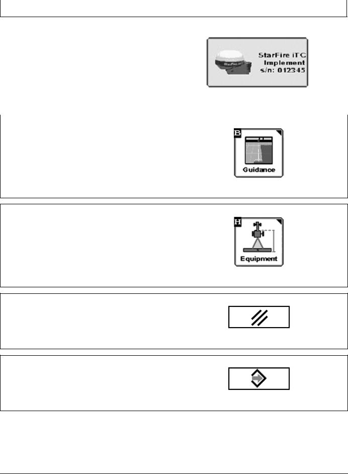
Use the STARFIRE IMPLEMENT Softkey to setup the |
PC9966 —UN—09FEB07 |
|
|
implement Receiver and start the TCM calibration for this |
|
receiver. The Serial Number of the receiver is shown on |
|
this button. |
|
NOTE: The implement receiver must be a StarFire iTC. |
|
|
STARFIRE IMPLEMENT Softkey |
|
CZ76372,00001CC 1912OCT105/11 |
|
|
|
|
Press the GUIDANCE Softkey to input required |
PC12947 —UN—12OCT10 |
|
|
information on desired Guidance Operation. |
|
Guidance Softkey
CZ76372,00001CC 1912OCT106/11
Press the EQUIPMENT Softkey to define Machine, |
PC12948 —UN—12OCT10 |
|
|
Implement and Implement receiver offsets. |
|
EQUIPMENT Softkey
CZ76372,00001CC 1912OCT107/11
Use CANCEL button to ignore the changes made to this |
PC8582 —UN—01NOV05 |
page. |
|
CANCEL Button
CZ76372,00001CC 1912OCT108/11
Use ENTER button to accept the current changes and |
PC8649 —UN—01NOV05 |
|
|
get back to the last page. |
|
ENTER Button
Continued on next page |
CZ76372,00001CC 1912OCT109/11 |
104 |
PN=12 |
|
102110 |
Getting Started |
|
|
|
|
|
|
|
|
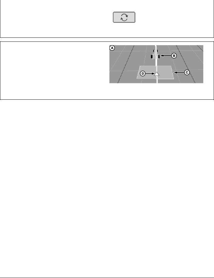
Use Offset Toggle button to toggle lateral offset from left |
PC10846 —UN—07DEC07 |
|
|
|
|
to right and vice versa. |
|
|
Offset Toggle Button
CZ76372,00001CC 1912OCT1010/11
Machine icon on guidance screen represents the location of the machine.
Implement icon on guidance screen represents the location of the implement.
Guidance reference point on guidance screen represents the location of the guidance point for the system.
A—Guidance Screen |
C—Implement Icon |
B—Machine Icon |
D—Guidance Reference Icon |
PC11041 —UN—19FEB08
Guidance Screen Icons
CZ76372,00001CC 1912OCT1011/11
105 |
PN=13 |
|
102110 |
Setup
Getting Started
To make iGuide function, the following criteria are required to be setup:
•Machine setup and offsets
•Implement setup and offsets
•Machine GPS receiver settings under StarFire softkey
•Implement GPS receiver settings under StarFire softkey
•Guidance Setting—Tracking mode, Implement Guidance Mode, and iGuide settings
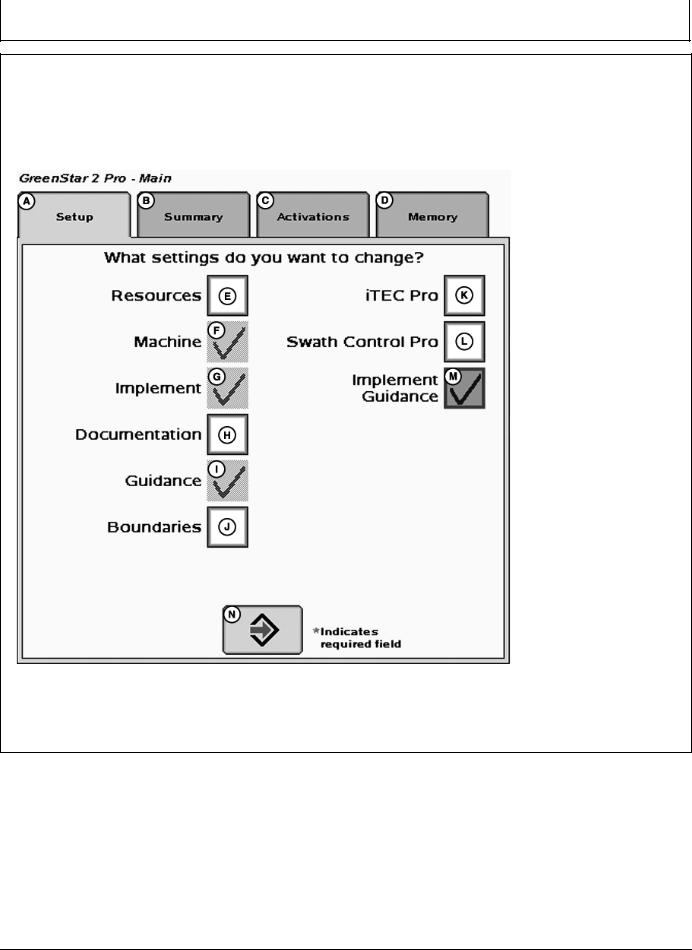
These items can be set up separately or the Setup Wizard can be used by checking the Implement Guidance option
(M). To access the Setup Wizard, select Softkey (F) (GreenStar).
|
|
|
PC11791 —UN—09MAR09 |
|
Setup Wizard |
|
|
A—Setup Tab |
E—Resources Check Box |
I— Guidance Check Box |
M—Implement Guidance Check |
B—Summary Tab |
F—Machine Check Box |
J—Boundaries Check Box |
Box |
C—Activations Tab |
G—Implement Check Box |
K—iTEC Pro Check Box |
N—Next Page |
D—Memory Tab |
H—Documentation Check Box |
L—Swath Control Pro Check Box |
|
CZ76372,00001CD 1906OCT101/1
151 |
PN=14 |
|
102110 |

Setup
Machine Setup
MENU >> GREENSTAR >> EQUIPMENT allows access to MACHINE and IMPLEMENT setup screens.
PC8663 —UN—05AUG05
MENU Softkey
PC12685 —UN—14JUL10
GREENSTAR 3 Softkey
PC12948 —UN—12OCT10
EQUIPMENT Softkey
Continued on next page |
CZ76372,00001CE 1912OCT101/2 |
152 |
PN=15 |
|
102110 |

Setup
PC10802 —UN—08JUL08
Machine Tab
A—Machine Tab |
D—Machine Model DropDown |
G—Machine Turn Radius |
J—RecordingSourceDropDown |
B—Implement 1 Tab |
Menu |
InputBox |
Menu |
C—Machine Type DropDown |
E—Machine Name DropDown |
H—Turning Sensitivity InputBox |
K—Record/Pause Button |
Menu |
Menu |
I— Change Offsets Button |
L—Enable Monitoring Without |
|
F—Connection Point DropDown |
|
GPS Check Box |
|
Menu |
|
|
NOTE: Machine name must be defined in order to change offsets. All offsets will be saved under the current machine name.
The Machine tab is required to be populated with the following equipment information:
•Machine Type—Vehicle type being used (Example: Tractor).
•Machine Name—Allows the operator to save vehiclespecific offsets.
•Connection Type—Defines how the implement is attached to the machine.
Rear Rigid 3pt (not compatible with iGuide)
Rear Pivot 2pt
Rear Pivot Drawbar
Rear Pivot Wagon Hitch (for European use)
Front Rigid 3pt (not compatible with iGuide)
•Machine Offsets—modify by pressing Change Offsets button (I).
•Verify offsets correspond to the machine selected.
Machine Model—Model number of the vehicle being used. For John Deere vehicles, model numbers will be available from the dropdown list.
NOTE: MachineModelisnotrequiredforiGuideoperation.
NOTE: Machine Turn Radius and Turning Sensitivity are for use with iTEC Pro only.
CZ76372,00001CE 1912OCT102/2
153 |
PN=16 |
|
102110 |
Loading...