


STX30, STX38, and STX46
Lawn Tractors
TECHNICAL
MANUAL
John Deere
Worldwide Commercial and
Consumer Equipment Division
TM1561 (15Mar97)
Replaces TM1561 (01Sep95) and
TM1418 (26Oct92)
Litho in U.S.A

|
|
|
|
|
|
|
|
M55912 |
|
|
|
M55913 |
|
|
|
|
|
|
|
|
|
|
|
|
|
|
|
STX38 Gear Drive |
|
STX38 Hydrostatic Drive |
||||
M85680
STX38 Motorsport Edition
|
|
|
|
|
|
|
|
M58332 |
|
|
|
M58333 |
|
|
|
|
|
|
|
|
|
|
|
|
|
|
|
STX46 Gear Drive |
STX46 Hydrostatic Drive |
|
||||

INTRODUCTION
This technical manual is written for an experienced technician and contains sections that are specifically for this product. It is a part of a total product support program.
Safety
The manual is organized so that all the information on a particular system is kept together. The order of grouping is as follows:
•Table of Contents
•Specifications
•Theory of Operation
•Troubleshooting Diagram
•Diagnostics
•Tests & Adjustments
•Repair
Note: Depending on the particular section or system being covered, not all of the above groups may be used.
Each section will be identified with a symbol rather than a number. The groups and pages within a section will be consecutively numbered.
Specifications and |
Information |
Engine
Electrical
Power Train
(Gear)
Power Train
Power(Hydrostatic)Train
Steering |
All information, illustrations and specifications in this manual are based on the latest information available at the time of publication. The right is reserved to make changes at any time without notice.
We appreciate your input on this manual. To help, there are postage paid post cards included at the back. If you find any errors or want to comment on the layout of the manual please fill out one of the cards and mail it back to us.
COPYRIGHT© 1997
JOHN DEERE HORICON WORKS
Horicon, Wisconsin
All rights reserved
Miscellaneous
3/12/97 |
1 - 1 |

SAFETY
|
RECOGNIZE SAFETY |
HANDLE FLUIDS SAFELY-AVOID |
|
INFORMATION |
FIRES |
|
|
Be Prepared For Emergencies |
|
|
This is the safety-alert symbol. When you see this symbol on your machine or in this manual, be alert to the potential for personal injury.
Follow recommended precautions and safe servicing practices.
Understand Signal Words
A signal word—DANGER, WARNING, or CAUTION— is used with the safety-alert symbol. DANGER identifies the most serious hazards.
DANGER or WARNING safety signs are located near specific hazards. General precautions are listed on CAUTION safety signs. CAUTION also calls attention to safety messages in this manual.
REPLACE SAFETY SIGNS
Replace missing or damaged safety signs. See the machine operator’s manual for correct safety sign placement.
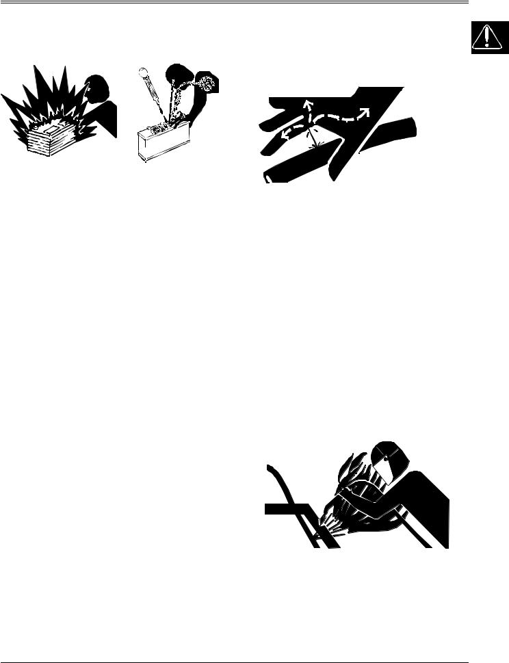
When you work around fuel, do not smoke or work near heaters or other fire hazards.
Store flammable fluids away from fire hazards. Do not incinerate or puncture pressurized containers.
Make sure machine is clean of trash, grease, and debris.
Do not store oily rags; they can ignite and burn spontaneously.
Be prepared if a fire starts.
Keep a first aid kit and fire extinguisher handy.
Keep emergency numbers for doctors, ambulance service, hospital, and fire department near your telephone.
1 - 2 |
3/12/97 |
SAFETY
USE CARE IN HANDLING AND SERVICING BATTERIES
Prevent Battery Explosions
•Keep sparks, lighted matches, and open flame away from the top of battery. Battery gas can explode.
•Never check battery charge by placing a metal object across the posts. Use a volt-meter or hydrometer.
•Do not charge a frozen battery; it may explode. Warm battery to 16°C (60°F).
Prevent Acid Burns
•Sulfuric acid in battery electrolyte is poisonous. It is strong enough to burn skin, eat holes in clothing, and cause blindness if splashed into eyes.
•Avoid acid burns by:
1.Filling batteries in a well-ventilated area.
2.Wearing eye protection and rubber gloves.
3.Avoiding breathing fumes when electrolyte is added.
4.Avoiding spilling or dripping electrolyte.
5.Use proper jump start procedure.
•If you spill acid on yourself:
1.Flush your skin with water.
2.Apply baking soda or lime to help neutralize the acid.
3.Flush your eyes with water for 10_15 minutes.
4.Get medical attention immediately.
•If acid is swallowed:
1.Drink large amounts of water or milk.
2.Then drink milk of magnesia, beaten eggs, or vegetable oil.
3.Get medical attention immediately.
USE CARE AROUND HIGH-
PRESSURE FLUID LINES
Avoid High-pressure Fluids
Escaping fluid under pressure can penetrate the skin causing serious injury.
Avoid injury from escaping fluid under pressure by stopping the engine and relieving pressure in the system before disconnecting or connecting hydraulic or other lines. Tighten all connections before applying pressure.
Search for leaks with a piece of cardboard. Protect hands and body from high pressure fluids.
If an accident occurs, see a doctor immediately. Any fluid injected into the skin must be surgically removed within a few hours or gangrene may result. Doctors unfamiliar with this type of injury should reference a knowledgeable medical source. Such information is available from Deere & Company Medical Department in Moline, Illinois, U.S.A.
Avoid Heating Near Pressurized
Fluid Lines
Flammable spray can be generated by heating near pressurized fluid lines, resulting in severe burns to yourself and bystanders. Do not heat by welding, soldering, or using a torch near pressurized fluid lines or other flammable materials. Pressurized lines can be accidentally cut when heat goes beyond the immediate flame area.
3/12/97 |
1 - 3 |
SAFETY
USE SAFE SERVICE PROCEDURES Park Machine Safely
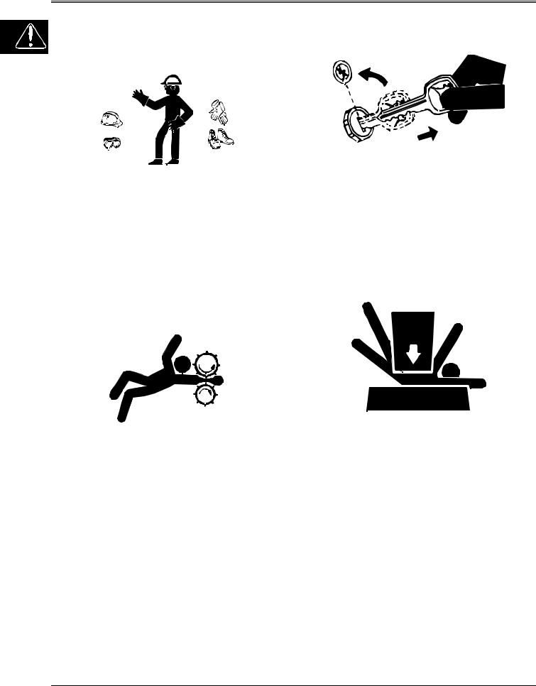
Wear Protective Clothing
Wear close fitting clothing and safety equipment appropriate to the job.
Prolonged exposure to loud noise can cause impairment or loss of hearing. Wear a suitable hearing protective device such as earmuffs or earplugs to protect against objectionable or uncomfortable loud noises.
Operating equipment safely requires the full attention of the operator. Do not wear radio or music headphones while operating machine.
Service Machines Safely
Tie long hair behind your head. Do not wear a necktie, scarf, loose clothing, or necklace when you work near machine tools or moving parts. If these items were to get caught, severe injury could result.
Remove rings and other jewelry to prevent electrical shorts and entanglement in moving parts.
Use Proper Tools
Use tools appropriate to the work. Makeshift tools and procedures can create safety hazards. Use power tools only to loosen threaded parts and fasteners. For loosening and tightening hardware, use the correct size tools. DO NOT use U.S. measurement tools on metric fasteners. Avoid bodily injury caused by slipping wrenches. Use only service parts meeting John Deere specifications.
Before working on the machine:
1.Lower all equipment to the ground.
2.Stop the engine and remove the key.
3.Disconnect the battery ground strap.
4.Hang a “DO NOT OPERATE” tag in operator station.
Support Machine Properly And Use
Proper Lifting Equipment
If you must work on a lifted machine or attachment, securely support the machine or attachment.
Do not support the machine on cinder blocks, hollow tiles, or props that may crumble under continuous load. Do not work under a machine that is supported solely by a jack. Follow recommended procedures in this manual.
Lifting heavy components incorrectly can cause severe injury or machine damage. Follow recommended procedure for removal and installation of components in the manual.
Work In Clean Area
Before starting a job:
1.Clean work area and machine.
2.Make sure you have all necessary tools to do your job.
3.Have the right parts on hand.
4.Read all instructions thoroughly; do not attempt shortcuts.
1 - 4 |
3/12/97 |
SAFETY
Using High Pressure Washers
Directing pressurized water at electronic/electrical components or connectors, bearings, hydraulic seals, fuel injection pumps or other sensitive parts and components may cause product malfunctions. Reduce pressure and spray at a 45 to 90 degree angle.
Illuminate Work Area Safely
Illuminate your work area adequately but safely. Use a portable safety light for working inside or under the machine. Make sure the bulb is enclosed by a wire cage. The hot filament of an accidentally broken bulb can ignite spilled fuel or oil.
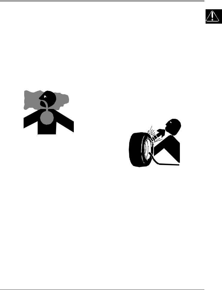
Work In Ventilated Area
Engine exhaust fumes can cause sickness or death. If it is necessary to run an engine in an enclosed area, remove the exhaust fumes from the area with an exhaust pipe extension.
If you do not have an exhaust pipe extension, open the doors and get outside air into the area.
Avoid Harmful Asbestos Dust
Avoid breathing dust that may be generated when handling components containing asbestos fibers. Inhaled asbestos fibers may cause lung cancer.
Components in products that may contain asbestos fibers are brake pads, brake band and lining assemblies, clutch plates, and some gaskets. The asbestos used in these components is usually found in a resin or sealed in some way. Normal handling is not hazardous as long as airborne dust containing asbestos is not generated.
Avoid creating dust. Never use compressed air for cleaning. Avoid brushing or grinding material containing asbestos. When servicing, wear an approved respirator. A special vacuum cleaner is recommended to clean asbestos. If not available, apply a mist of oil or water on the material containing asbestos. Keep bystanders away from the area.
SERVICE TIRES SAFELY
WARNING: California Proposition 65
Warning
Diesel engine exhaust and some of its constituents are known to the State of California to cause cancer, birth defects, and other reproductive harm.
Gasoline engine exhaust from this product contains chemicals known to the State of California to cause cancer, birth defects, or other reproductive harm.
Remove Paint Before Welding Or
Heating
Avoid potentially toxic fumes and dust. Hazardous fumes can be generated when paint is heated by welding, soldering, or using a torch. Do all work outside or in a well ventilated area. Dispose of paint and solvent properly. Remove paint before welding or heating: If you sand or grind paint, avoid breathing the dust. Wear an approved respirator. If you use solvent or paint stripper, remove stripper with soap and water before welding. Remove solvent or paint stripper containers and other flammable material from area. Allow fumes to disperse at least 15 minutes before welding or heating.
Explosive separation of a tire and rim parts can cause serious injury or death.
Do not attempt to mount a tire unless you have the proper equipment and experience to perform the job. Always maintain the correct tire pressure. Do not inflate the tires above the recommended pressure. Never weld or heat a wheel and tire assembly. The heat can cause an increase in air pressure resulting in a tire explosion. Welding can structurally weaken or deform the wheel.
When inflating tires, use a clip-on chuck and extension hose long enough to allow you to stand to one side and NOT in front of or over the tire assembly. Use a safety cage if available.
Check wheels for low pressure, cuts, bubbles, damaged rims or missing lug bolts and nuts.
3/12/97 |
1 - 5 |

SAFETY
AVOID INJURY FROM ROTATING BLADES, AUGERS AND PTO  SHAFTS
Keep hands and feet away while machine is running. Shut off power to service, lubricate or remove mower blades, augers or PTO shafts.
SERVICE COOLING SYSTEM SAFELY
Explosive release of fluids from pressurized cooling system can cause serious burns.
Shut off machine. Only remove filler cap when cool enough to touch with bare hands. Slowly loosen cap to first stop to relieve pressure before removing completely.
HANDLE CHEMICAL PRODUCTS SAFELY
Direct exposure to hazardous chemicals can cause serious injury. Potentially hazardous chemicals used with John Deere equipment include such items as lubricants, coolants, paints, and adhesives.
A Material Safety Data Sheet (MSDS) provides specific details on chemical products: physical and health hazards, safety procedures, and emergency response techniques. Check the MSDS before you start any job using a hazardous chemical. That way you will know exactly what the risks are and how to do the job safely. Then follow procedures and recommended equipment.
Dispose of Waste Properly
Improperly disposing of waste can threaten the environment and ecology. Potentially harmful waste used with John Deere equipment include such items as oil, fuel, coolant, brake fluid, filters, and batteries. Use leakproof containers when draining fluids. Do not use food or beverage containers that may mislead someone into drinking from them. Do not pour waste onto the ground, down a drain, or into any water source. Inquire on the proper way to recycle or dispose of waste from your local environmental or recycling center, or from your John Deere dealer.
LIVE WITH SAFETY
Before returning machine to customer, make sure machine is functioning properly, especially the safety systems. Install all guards and shields.
1 - 6 |
3/12/97 |

SPECIFICATIONS & INFORMATION |
CONTENTS |
|
|
CONTENTS
Page
SPECIFICATIONS & INFORMATION
GENERAL VEHICLE SPECIFICATIONS . . . . . . . . . . . . . . . . . . . . . . . . . 3 METRIC FASTENER TORQUE VALUES. . . . . . . . . . . . . . . . . . . . . . . . . 6
METRIC FASTENER TORQUE VALUE - GRADE 7. . . . . . . . . . . . . . . . . . . . . . . . . . 7
INCH FASTENER TORQUE VALUES . . . . . . . . . . . . . . . . . . . . . . . . . . . 8 O-RING SEAL SERVICE RECOMMENDATIONS . . . . . . . . . . . . . . . . . . 9
FACE SEAL FITTINGS WITH INCH STUD ENDS TORQUE . . . . . . . . . . . . . . . . . . . 9 FACE SEAL FITTINGS WITH METRIC STUD ENDS TORQUE . . . . . . . . . . . . . . . 10 O-RING FACE SEAL FITTINGS . . . . . . . . . . . . . . . . . . . . . . . . . . . . . . . . . . . . . . . . 11 O-RING BOSS FITTINGS . . . . . . . . . . . . . . . . . . . . . . . . . . . . . . . . . . . . . . . . . . . . . 11
GASOLINE SPECIFICATIONS. . . . . . . . . . . . . . . . . . . . . . . . . . . . . . . . 12
4–CYCLE ENGINES - NORTH AMERICA . . . . . . . . . . . . . . . . . . . . . . . . . . . . . . . . 12 GASOLINE STORAGE . . . . . . . . . . . . . . . . . . . . . . . . . . . . . . . . . . . . . . . . . . . . . . . 12 4–CYCLE ENGINES - EUROPE . . . . . . . . . . . . . . . . . . . . . . . . . . . . . . . . . . . . . . . . 13 GASOLINE STORAGE . . . . . . . . . . . . . . . . . . . . . . . . . . . . . . . . . . . . . . . . . . . . . . . 13
4–CYCLE GASOLINE ENGINE OIL . . . . . . . . . . . . . . . . . . . . . . . . . . . . 14
4–CYCLE GASOLINE ENGINE OIL - NORTH AMERICA . . . . . . . . . . . . . . . . . . . . 14 4–CYCLE GASOLINE ENGINE OIL - EUROPE . . . . . . . . . . . . . . . . . . . . . . . . . . . . 15 BREAK–IN 4-CYCLE GASOLINE ENGINE OIL - NORTH AMERICA . . . . . . . . . . . 16 BREAK–IN 4-CYCLE GASOLINE ENGINE OIL - EUROPE . . . . . . . . . . . . . . . . . . . 17
HYDROSTATIC TRANSMISSION OIL . . . . . . . . . . . . . . . . . . . . . . . . . . 18
HYDROSTATIC TRANSMISSION OIL - NORTH AMERICA . . . . . . . . . . . . . . . . . . 18 HYDROSTATIC TRANSMISSION OIL - EUROPE . . . . . . . . . . . . . . . . . . . . . . . . . . 19
ALTERNATIVE LUBRICANTS . . . . . . . . . . . . . . . . . . . . . . . . . . . . . . . . 20
SYNTHETIC LUBRICANTS. . . . . . . . . . . . . . . . . . . . . . . . . . . . . . . . . . . . . . . . . . . . 20 LUBRICANT STORAGE . . . . . . . . . . . . . . . . . . . . . . . . . . . . . . . . . . . . . . . . . . . . . . 20 MIXING OF LUBRICANTS . . . . . . . . . . . . . . . . . . . . . . . . . . . . . . . . . . . . . . . . . . . . 20 OIL FILTERS . . . . . . . . . . . . . . . . . . . . . . . . . . . . . . . . . . . . . . . . . . . . . . . . . . . . . . . 20
GEAR TRANSMISSION GREASE . . . . . . . . . . . . . . . . . . . . . . . . . . . . . 21 ANTI-CORROSION GREASE SPECIFICATIONS . . . . . . . . . . . . . . . . . 22 GREASE SPECIFICATIONS . . . . . . . . . . . . . . . . . . . . . . . . . . . . . . . . . 23
GREASE - NORTH AMERICA . . . . . . . . . . . . . . . . . . . . . . . . . . . . . . . . . . . . . . . . . 23 GREASE - EUROPE . . . . . . . . . . . . . . . . . . . . . . . . . . . . . . . . . . . . . . . . . . . . . . . . . 23
SERIAL NUMBER LOCATIONS. . . . . . . . . . . . . . . . . . . . . . . . . . . . . . . 24
ENGINE SERIAL NUMBER SUFFUX . . . . . . . . . . . . . . . . . . . . . . . . . . . . . . . . . . . . 24 TRACTOR IDENTIFICATION NUMBER . . . . . . . . . . . . . . . . . . . . . . . . . . . . . . . . . . 24 ENGINE SERIAL NUMBER. . . . . . . . . . . . . . . . . . . . . . . . . . . . . . . . . . . . . . . . . . . . 24 GEAR TRANSAXLE SERIAL NUMBER . . . . . . . . . . . . . . . . . . . . . . . . . . . . . . . . . . 24 HYDROSTATIC TRANSMISSION SERIAL NUMBER . . . . . . . . . . . . . . . . . . . . . . . 24
3/12/97 |
2 - 1 |

|
|
NOTES |
SPECIFICATIONS & INFORMATION |
|
|
|
|
|
|
|
|
|
|
|
|
|
|
|
|
2 - 2 |
3/12/97 |
SPECIFICATIONS AND INFORMATION |
GENERAL VEHICLE SPECIFICATIONS |
|
|
|
|
GENERAL VEHICLE SPECIFICATIONS
Engine:
Make . . . . . . . . . . . . . . . . . . . . . . . . . . . . . . . . . . . . . . . . . . . . . . . . . . . . . . . . . . . Kohler Style . . . . . . . . . . . . . . . . . . . . . . . . . . . . . . . . . . . . . . . . . . . . . . . . . . . . . .Command LT STX30 . . . . . . . . . . . . . . . . . . . . . . . . . . . . . . . . . . . . . . . . . . . . . . . . . . CV12.5—1216s STX38 (Serial No. —270000) . . . . . . . . . . . . . . . . . . . . . . . . . . . .CV12.5—1215 STX38 (Serial No. 210001—270000) . . . . . . . . . . . . . . . . . . . . . . . . . . . .CV12.5—1270 STX38 (Serial No. 270001—595000 & Motorsport) . . . . . . . . . . . . . . . . CV13S—21509 STX46 (Serial No. 210001—270000) . . . . . . . . . . . . . . . . . . . . . . . . . . . . CV14S—1463 STX46 (Serial No. 270001—595000) . . . . . . . . . . . . . . . . . . . . . . . . . . . CV15S—41521 Type . . . . . . . . . . . . . Gasoline, Air Cooled, Single Cylinder, 4-Cycle, Overhead Valves Crankcase Oil Capacity (with filter) . . . . . . . . . . . . . . . . . . . . . . . . . . . 1.8 L (1.9 U.S. qt) Oil Type: (Warm Climate) . . . . . . . . . . . . . . . . . . . . . . . . . . . . . . . . . . . . . . . . . . . 10W30
(Cold Climate). . . . . . . . . . . . . . . . . . . . . . . . . . . . . . . . . . . . . . . . . . . . . . 5W30
Electrical:
Charging System. . . . . . . . . . . . . . . . . . . . . . . . . . . . . . . . Flywheel/Electronic Magneto
Magneto Air Gap . . . . . . . . . . . . . . . . . . . . . . . . . . . . . . 0.2—0.3 mm (0.008—0.012 in.)
Charging Capacity. . . . . . . . . . . . . . . . . . . . . . . . . . . . . . . . . . . . . . . 15 amp (regulated)
Spark Plug. . . . . . . . . . . . . . . . . . . . . . . . . . . . . . . . . . . . . . . . . . . . .Champion RC12YC
Spark Plug Air Gap . . . . . . . . . . . . . . . . . . . . . . . . . . . . . . . . . . . . . . . 1.0 mm (0.040 in.)
Battery Type . . . . . . . . . . . . . . . . . . . . . . . . . . . . . . . . . . . . . . . . . . . . . . .BCI Group, U1
Battery Reserve Capacity . . . . . . . . . . . . . . . . . . . . . . . . . . . . . . . . . . 23 min. at 25 amp
Battery Cold Cranking Amp. . . . . . . . . . . . . . . . . .25 amp at 27° C (0° F) for 20 minutes
Battery Specific Gravity. . . . . . . . . . . . . . . . . . . . . . . . . . . . . . . . . . . Above 1.225 Points
Starter Type . . . . . . . . . . . . . . . . . . . . . . . . . . . . . . . . . . . . . . . . . . . Bendix Inertia Drive
PTO Clutch Type. . . . . . . . . . . . . . . . . . . . . . . . . . . . Electric (Manufactured by Warner)
Fuel Shut-Off Solenoid (Optional) . . . . . . . . Replaceable (Below Carburetor Float Bowl)
Headlight Kit (Optional) . . . . . . . . . . . . . . Two Bulbs—Each 12 Volt/23W/1.9 Amp Draw
Fuel/Air System:
Carburetor Make . . . . . . . . . . . . . . . . . . . . . . . . . . . . . . . . . . . . . . . . . . . . . . . . . . Walbro
Carburetor Type . . . . . . . . . . . . . . . . . . . . . . . . . . . . . . . . . . . . . . . . . . . . . . . Side Draft
Throttle/Choke. . . . . . . . . . . . . . . . . . . . . . . . . . . . . . . . . . . . . . Unitized Control Linkage
Carburetor Fuel Shut-Off Solenoid (Optional). . . . . . . . . . . . . . . . . . . . . . . . . . . .Electric
Fuel Delivery . . . . . . . . . . . . . . . . . . . . . . . . . . . . . . . . . . . . . . . . . . . . . . . . Gravity Flow
Fuel Filter . . . . . . . . . . . . . . . . . . . . . . . . . . . . . . . . . . . Replaceable Paper (in-line type)
Fuel Type . . . . . . . . . . . . . . . . . . . . . . . . . . . . . . . . . . . Unleaded (87 octane minimum)
Fuel Tank Capacity . . . . . . . . . . . . . . . . . . . . . . . . . . . . . . . . . . . . . . . . . 4.7 L (1.25 gal)
Air Filter. . . . . . . . . . . . . . . . . . . . . . . . . . . . . . . . Paper Element with Foam Pre-cleaner
Muffler Type . . . . . . . . . . . . . . . . . . . . . . . . . . . . . . . . . . . . . . . . . . . . . . . . Anti-Backfire
Power Train:
Gear Transaxle—
Make . . . . . . . . . . . . . . . . . . . . . . . . . . . . . . . . . . . . . . . . . . . . . . . . . . . . . . . . . . . . Dana Model . . . . . . . . . . . . . . . . . . . . . . . . . . . . . . . . . . . .Spicer Heavy-Duty 4360 Transaxle Type . . . . . . . . . . . . . . . . . . . . . . . . . . . . . . . . . . . . . . . . . . . . . .Five-Speed/Linear Shift Domestic Ground Speeds (at FAST idle—3350 rpm) and Gear Ratios:
1st Gear . (STX30 & STX38 SN —210000 2.2km/hr) 2.4 km/hr (1.5 mph)—61.67:1 2nd Gear. . . . . . . . . . . . . . . . . . . . . . . . . . . . . . . . . . . . . 3.2 km/hr (2.0 mph)—46.67:1 3rd Gear . (STX30 & STX38 SN —210000 4.5km/hr) 5.0 km/hr (3.1 mph)—30.00:1 4th Gear . (STX30 & STX38 SN —210000 5.7km/hr) 6.4 km/hr (4.0 mph)—23.48:1 5th Gear . (STX30 & STX38 SN —210000 8.5km/hr) 8.0 km/hr (5.0 mph)—15.71:1 Reverse . . (STX30 & STX38 SN —210000 3.3km/hr) 3.7 km/hr (2.3 mph)—40.00:1
Export Ground Speeds (at FAST idle—3000 rpm) and Gear Ratios:
1st Gear . . . . . . . . . . . . . . . . . . . . . . . . . . . . . . . . . . . 1.97 km/hr (1.22 mph)—61.67:1 2nd Gear. . . . . . . . . . . . . . . . . . . . . . . . . . . . . . . . . . . 2.61 km/hr (1.67 mph)—46.67:1 3rd Gear . . . . . . . . . . . . . . . . . . . . . . . . . . . . . . . . . . . 4.07 km/hr (2.53 mph)—30.00:1 4th Gear . . . . . . . . . . . . . . . . . . . . . . . . . . . . . . . . . . . 5.18 km/hr (3.22 mph)—23.48:1 5th Gear . . . . . . . . . . . . . . . . . . . . . . . . . . . . . . . . . . . 7.76 km/hr (4.82 mph)—15.71:1 Reverse . . . . . . . . . . . . . . . . . . . . . . . . . . . . . . . . . . . 3.04 km/hr (1.89 mph)—40.00:1
Brake Type . . . . . . . . . . . . . . . . . .Single, External Brake Disc With Dual Friction Pucks
3/20/97 |
2 - 3 |

GENERAL VEHICLE SPECIFICATIONS |
SPECIFICATIONS AND INFORMATION |
|
|
|
|
Power Train: (Continued)
Lubrication—Input Shaft Needle Bearings . . . . . . . . . . . . . . . .Unirex® N3 Grease Only
Lubrication—Transaxle . . . . . . . . . . . . . . . . . . . . . . . . . . . Shell Darina® D Grease Only
Capacity—Transaxle. . . . . . . . . . . . . . . . . . . . . . . . . . . . . . . . . . . . . .0.64 kg (1.406 lbs)
Hydro Transaxle—
Make . . . . . . . . . . . . . . . . . . . . . . . . . . . . . . . . . . . . . . . . . . . . . . . . . . . . . . . . . . Kanzaki
Model (STX38—early models) . . . . . . . . . . . . . . . . . . . . . . . . Tuff Torq® K50 Transaxle
Model (STX38—late models) . . . . . . . . . . . . . . . . . . . . . . . . . Tuff Torq® K55 Transaxle
Model (STX46) . . . . . . . . . . . . . . . . . . . . . . . . . . . . . . . . . . . . Tuff Torq® K55 Transaxle
Type . . . . . . . . . . . . . . . . . . . . . . . . . . . . . . . . . . . . . . . . . . . . . . . . . . . . . . . Hydrostatic
Domestic Ground Speeds (at FAST idle—3350 rpm):
Forward . . . . . . . . . . . . . . . . . . . . . . . . . . . . . . . . . . . . . . . 0—9.3 km/hr (0—5.8 mph)
Reverse . . . . . . . . . . . . . . . . . . . . . . . . . . . . . . . . . . . . . . . 0—4.7 km/hr (0—2.9 mph)
Export Ground Speeds (at FAST idle—3000 rpm):
Forward . . . . . . . . . . . . . . . . . . . . . . . . . . . . . . . . . . . . . 0—7.75 km/hr (0—4.82 mph)
Reverse . . . . . . . . . . . . . . . . . . . . . . . . . . . . . . . . . . . . . 0—3.80 km/hr (0—2.36 mph)
Brake Type . . . . . . . . . . . . . . . . . . . . . . Single, External Disc Brake With Friction Pucks
Lubrication. . . . . . . . . . . . . . . . . . . . . . John Deere Plus-4 10W30 Engine Oil, Class CD
Reservoir. . . . . . . . . . . . . . . . . . . . . . . . . . . . . . . . . . . . . . . . . . . . . . . . . . . . . . . Internal
Capacity . . . . . . . . . . . . . . . . . . . . . . . . . . . . . . . . . . . . . . . . . . . . . . . . . . . 1.6 L (3.4 pt)
Traction Drive Belt:
Gear—
Actual effective length . . . . . . . . . . . . . . . . . . . . . . . . . . . . . 2660±8 mm (104.7±0.3 in.)
Theoretical effective length (short) . . . . . . . . . . . . . . . . . . . . . . . . . 2631 mm (103.6 in.)
Theoretical effective length (long) . . . . . . . . . . . . . . . . . . . . . . . . . . 2710 mm (106.7 in.)
Hydro—
Actual effective length . . . . . . . . . . . . . . . . . . . . . . . . . . . . . . 2485±8 mm (97.8±0.3 in.)
Theoretical effective length (short) . . . . . . . . . . . . . . . . . . . . . . . . . . 2477 mm (97.5 in.)
Theoretical effective length (long) . . . . . . . . . . . . . . . . . . . . . . . . . . . 2530 mm (99.6 in.)
Mower Deck Drive Belt
38-Inch Deck—
Actual effective length . . . . . . . . . . . . . . . . . . . . . . . . . . . . . 2425±10 mm (95.5±0.4 in.)
46-Inch Deck—
Actual effective length . . . . . . . . . . . . . . . . . . . . . . . . . . . . 3492±10 mm (137.5±0.4 in.)
Mower Deck:
38-Inch Mower Deck—
Type . . . . . . . . . . . . . . . . . . . . . . . . . . . . . . . Rotary—Dual Spindles (Non-Serviceable)
Material Type . . . . . . . . . . . . . . . . . .Stamped 2.5 mm (0.098 in.) Nominal Gauge Steel
Cutting Blade. . . . . . . . . . . . . . . . . . . . . . . . . Two—76 x 5 x 496 mm (3 x 0.2 x 19.5 in.)
Blade Cutting Edge . . . . . . . . . . . . . . . . . . . . . . . . . . . . . . . . . . . . . . . . . . . .30±5° Angle
Blade Wing Lift/Height. . . . . . . . . . . . . . . . . . . . . . . . . . . . . . . . 40±3 mm (1.57±0.12 in.)
Overall Cutting Width . . . . . . . . . . . . . . . . . . . . . . . . . . . . . . . . . . . . . . . 965 mm (38 in.)
Overall Width (w/o discharge chute) . . . . . . . . . . . . . . . . . . . . . . . . . 1026 mm (40.4 in.)
Drive Type. . . . . . . . . . . . . . . . . . . . . . . . . . . Single V-Belt (with spring-tensioned idler)
Spindle Lubrication . . . . . . . . . . . . . . . . . . . . . . . . . . . . . . . . . . None—Sealed Bearings
Lift Type . . . . . . . . . . . . . . . . . . . . . . . . . . . . . . . . . . . . . . . Manual—Operator’s Station
Cutting Settings. . . . . . . . . . . . . . . . . . . . . . . . . . . .Seven: 31.8—89 mm (1.25—3.5 in.)
2 - 4 |
3/20/97 |

SPECIFICATIONS AND INFORMATION |
GENERAL VEHICLE SPECIFICATIONS |
|
|
|
|
Mower Deck: (Continued)
46-Inch Mower Deck—
Type . . . . . . . . . . . . . . . . . . . . . . . . . . . . . . . Rotary—Triple Spindles (Non-Serviceable)
Material Type . . . . . . . . . . . . . . . . . . Stamped 2.5 mm (0.098 in.) Nominal Gauge Steel
Cutting Blade . . . . . . . . . . . . . . . . . . . . . . Three—50.8 x 5 x 407.4 mm (2 x 0.2 x 16 in.)
Blade Cutting Edge . . . . . . . . . . . . . . . . . . . . . . . . . . . . . . . . . . . . . . . . . . . 30±5° Angle
Blade Wing Lift/Height . . . . . . . . . . . . . . . . . . . . . . . . . . . . . . . 20.3±3 mm (0.8±0.12 in.)
Overall Cutting Width . . . . . . . . . . . . . . . . . . . . . . . . . . . . . . . . . . . . . 1168.4 mm (46 in.)
Overall Width (w/o discharge chute) . . . . . . . . . . . . . . . . . . . . . . . . . 1308 mm (51.5 in.)
Drive Type . . . . . . . . . . . . . . . . . . . . . . . . . . . Single V-Belt (with spring-tensioned idler)
Spindle Lubrication. . . . . . . . . . . . . . . . . . . . . . . . . . . . . . . . . . None—Supplier Fill Only
Lift Type . . . . . . . . . . . . . . . . . . . . . . . . . . . . . . . . . . . . . . . . Manual—Operator’s Station
Cutting Settings . . . . . . . . . . . . . . . . . . . . . . . Seven: 31.75 mm—89 mm (1.25—3.5 in.)
Chassis:
Wheelbase . . . . . . . . . . . . . . . . . . . . . . . . . . . . . . . . . . . . . . . . . . . . 1135 mm (44.69 in.)
Overall Length . . . . . . . . . . . . . . . . . . . . . . . . . . . . . . . . . . . . . . . . . . . 1524 mm (60 in.)
Overall Width (w/o mower deck) . . . . . . . . . . . . . . . . . . . . . . . . . . . . 908 mm (35.75 in.)
Height. . . . . . . . . . . . . . . . . . . . . . . . . . . . . . . . . . . . . . . . . . . . . . . . . . 980 mm (38.6 in.)
Average Overall Weight STX38 (with mower deck/no fuel) . . . . . . . .195.05 kg (430 lbs)
Average Overall Weight STX46 (with mower deck/no fuel) . . . . . . . .204.12 kg (450 lbs)
Hitch Capacity—
Export:
Horizontal Pull Maximum . . . . . . . . . . . . . . . . . . . . . . . . . . . . . . . . . . .250 N (56 lbs)
Tongue Weight Maximum . . . . . . . . . . . . . . . . . . . . . . . . . . . . . . . . . . .65 N (15 lbs)
Domestic:
Trailer Load Maximum . . . . . . . . . . . . . . . . . . . . . . . . . . . . . . . . . . . 136 kg (300 lbs)
Trailer Tongue Weight Maximum . . . . . . . . . . . . . . . . . . . . . . . . . . . . . 23 kg (50 lbs)
Steering:
Type . . . . . . . . . . . . . . . . . . . . . . . . . . . . . . . . . . . . . . . . . . . . . . .Manual—Pinion/Sector
Axle Pivot Hub . . . . . . . . . . . . . . . . . . . . . . . . . . . . . . . . . . . . . . . . . . . . Shim Adjustable
Lubrication . . . . . . . . . . . . . . . . . . . . . . . . . . . . . DuBois MPG-2® Multipurpose Grease
Lubrication Interval. . . . . . . . . . . . . . . . . . . . . . . . . . . . . . . . . . . . . . . 10 hrs (maximum)
Toe-In. . . . . . . . . . . . . . . . . . . . . . . . . . . . . . . . . . . . . 6 mm (0.24 in.) — Non-Adjustable
Turning Radius. . . . . . . . . . . . . . . . . . . . . . . . . . . . . . . . . . . . . . . . . . . . 584 mm (23 in.)
Wheels:
Size—
Front . . . . . . . . . . . . . . . . . . . . . . . . . . . . . . . . . . . . . . . . . . . . . . . . . . . . . . . 6.0 x 4.50
Rear. . . . . . . . . . . . . . . . . . . . . . . . . . . . . . . . . . . . . . . . . . . . . . . . . . . . . . . . 8.0 x 6.18
Tires:
Size—
Front (STX30) . . . . . . . . . . . . . . . . . . . . . . . . . . . . . . . . . . . . . . 13 x 5—6 NHS (2 ply)
Rear (STX30) . . . . . . . . . . . . . . . . . . . . . . . . . . . . . . . . . . . . 18 x 6.50—8 NHS (2 ply)
Front (STX38 SN —210000) . . . . . . . . . . . . . . . . . . . . . . . 13 x 6.50—6 NHS (2 ply)
Rear (STX38 SN —210000). . . . . . . . . . . . . . . . . . . . . . . . 18 x 8.50—8 NHS (2 ply)
Front (STX38 SN 210001—270000) . . . . . . . . . . . . . . . . . . . 13 x 6.50—6 NHS (2 ply)
Rear (STX38 SN 210001—270000) . . . . . . . . . . . . . . . . . . . 18 x 9.50—8 NHS (2 ply)
Front (STX38 SN 270001—595000 & STX46) . . . . . . . . . . . 15 x 6.50—6 NHS (2 ply)
Rear (STX38 SN 270001—595000 & STX46) . . . . . . . . . . . 20 x 8.00—8 NHS (2 ply)
Pressure—
Front (with mower deck) . . . . . . . . . . . . . . . . . . . . . . . . . . . . . . . . . . . . 83 kPa (12 psi)
Front (with snowthrower) . . . . . . . . . . . . . . . . . . . . . . . . . . . . . . . . . . . 138 kPa (20 psi)
Rear (STX30 with mower deck). . . . . . . . . . . . . . . . . . . . . . . . . . . . . . . 97 kPa (14 psi)
Rear (with mower deck). . . . . . . . . . . . . . . . . . . . . . . . . . . . . . . . . . . . . . 55 kPa (8 psi)
3/20/97 |
2 - 5 |
METRIC FASTENER TORQUE VALUES |
SPECIFICATIONS AND INFORMATION |
|
|
|
|
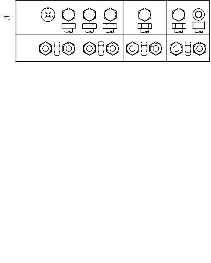
METRIC FASTENER TORQUE VALUES
|
|
4.8 |
|
|
8.8 |
9.8 |
|
|||||||||||||||
|
Property |
|
|
|
|
|
|
|
|
|
|
|
|
|
|
|
|
|
|
|
|
|
|
Class |
|
|
|
|
|
|
|
|
|
|
|
|
|
|
|
|
|
|
|
|
|
|
|
|
|
|
|
|
|
|
|
|
|
|
|
|
|
|
|
|
|
|
|
|
|
and |
|
|
|
|
|
4.8 |
|
8.8 |
9.8 |
|
|||||||||||
|
|
|
|
|
|
|
|
|||||||||||||||
|
Head |
|
|
|
|
|
|
|
|
|
|
|
|
|
|
|
|
|
|
|
|
|
|
Markings |
|
|
|
|
|
|
|
|
|
|
|
|
4.8 |
|
|
8.8 |
|
|
|
9.8 |
|
|
|
|
|
|
|
|
|
|
|
|
|
|
|
|
|
|
|
|
||||
|
Property |
5 |
|
|
|
|
|
10 |
|
|
|
|||||||||||
|
|
|
|
|
|
|
|
|
||||||||||||||
|
|
|
|
|
|
|
|
|
|
|
|
|
|
|
|
|
|
|
|
|
|
|
|
Class |
|
|
|
|
|
|
|
|
|
|
|
|
|
|
|
|
|
|
|
|
|
|
and |
5 |
|
|
|
|
|
10 |
|
|
|
|||||||||||
|
Nut |
|
|
|
|
|
|
|
|
|||||||||||||
|
5 |
|
|
|
|
|
|
|
|
|
|
|
10 |
|
|
|
|
|
||||
|
|
|
|
|
|
|
|
|
|
|
|
|
|
|
|
|
||||||
|
Markings |
|
|
|
|
|
|
|
|
|
|
|
|
|
|
|
|
|||||
|
|
|
|
|
|
|
|
|
|
|
|
|
|
|
|
|
|
|
|
|
|
|
|
|
|
|
|
|
|
|
|
|
|
|
|
|
|
|
|
|
|
|
|
|
|
10.9
 10.9
10.9
10.9
10

 10 10
10 10 


12.9
 12.9
12.9
12.9 12.9
12


 12 12
12 12 

TS1163
|
|
|
|
|
|
|
|
|
|
|
|
|
|
|
|
|
|
|
Class 4.8 |
|
|
Class 8.8 or 9.8 |
|
|
Class 10.9 |
|
|
Class 12.9 |
|
|
|||||
|
|
|
|
|
|
|
|
|
|
|
|
|
|
|
|
|
|
|
|
|
|
|
|
|
|
|
|
|
|
|
|
|
|
|
|
|
Lubricateda |
Drya |
|
Lubricateda |
|
Drya |
|
Lubricateda |
Drya |
|
Lubricateda |
Drya |
|
||||
SIZE |
N•m |
lb-ft |
N•m |
lb-ft |
N•m |
lb-ft |
|
N•m |
lb-ft |
N•m |
lb-ft |
N•m |
lb-ft |
N•m |
lb-ft |
N•m |
lb-ft |
|
|
|
|
|
|
|
|
|
|
|
|
|
|
|
|
|
|
M6 |
4.8 |
3.5 |
6 |
4.5 |
9 |
6.5 |
|
11 |
8.5 |
13 |
9.5 |
17 |
12 |
15 |
11.5 |
19 |
14.5 |
|
|
|
|
|
|
|
|
|
|
|
|
|
|
|
|
|
|
M8 |
12 |
8.5 |
15 |
11 |
22 |
16 |
|
28 |
20 |
32 |
24 |
40 |
30 |
37 |
28 |
47 |
35 |
|
|
|
|
|
|
|
|
|
|
|
|
|
|
|
|
|
|
M10 |
23 |
17 |
29 |
21 |
43 |
32 |
|
55 |
40 |
63 |
47 |
80 |
60 |
75 |
55 |
95 |
70 |
|
|
|
|
|
|
|
|
|
|
|
|
|
|
|
|
|
|
M12 |
40 |
29 |
50 |
37 |
75 |
55 |
|
95 |
70 |
110 |
80 |
140 |
105 |
130 |
95 |
165 |
120 |
|
|
|
|
|
|
|
|
|
|
|
|
|
|
|
|
|
|
M14 |
63 |
47 |
80 |
60 |
120 |
88 |
|
150 |
110 |
175 |
130 |
225 |
165 |
205 |
150 |
260 |
109 |
|
|
|
|
|
|
|
|
|
|
|
|
|
|
|
|
|
|
M16 |
100 |
73 |
125 |
92 |
190 |
140 |
|
240 |
175 |
275 |
200 |
350 |
225 |
320 |
240 |
400 |
300 |
|
|
|
|
|
|
|
|
|
|
|
|
|
|
|
|
|
|
M18 |
135 |
100 |
175 |
125 |
260 |
195 |
|
330 |
250 |
375 |
275 |
475 |
350 |
440 |
325 |
560 |
410 |
|
|
|
|
|
|
|
|
|
|
|
|
|
|
|
|
|
|
M20 |
190 |
140 |
240 |
180 |
375 |
275 |
|
475 |
350 |
530 |
400 |
675 |
500 |
625 |
460 |
800 |
580 |
|
|
|
|
|
|
|
|
|
|
|
|
|
|
|
|
|
|
M22 |
260 |
190 |
330 |
250 |
510 |
375 |
|
650 |
475 |
725 |
540 |
925 |
675 |
850 |
625 |
1075 |
800 |
|
|
|
|
|
|
|
|
|
|
|
|
|
|
|
|
|
|
M24 |
330 |
250 |
425 |
310 |
650 |
475 |
|
825 |
600 |
925 |
675 |
1150 |
850 |
1075 |
800 |
1350 |
1000 |
|
|
|
|
|
|
|
|
|
|
|
|
|
|
|
|
|
|
M27 |
490 |
360 |
625 |
450 |
950 |
700 |
|
1200 |
875 |
1350 |
1000 |
1700 |
1250 |
1600 |
1150 |
2000 |
1500 |
|
|
|
|
|
|
|
|
|
|
|
|
|
|
|
|
|
|
M30 |
675 |
490 |
850 |
625 |
1300 |
950 |
|
1650 |
1200 |
1850 |
1350 |
2300 |
1700 |
2150 |
1600 |
2700 |
2000 |
|
|
|
|
|
|
|
|
|
|
|
|
|
|
|
|
|
|
M33 |
900 |
675 |
1150 |
850 |
1750 |
1300 |
|
2200 |
1650 |
2500 |
1850 |
3150 |
2350 |
2900 |
2150 |
3700 |
2750 |
|
|
|
|
|
|
|
|
|
|
|
|
|
|
|
|
|
|
M36 |
1150 |
850 |
1450 |
1075 |
2250 |
1650 |
|
2850 |
2100 |
3200 |
2350 |
4050 |
3000 |
3750 |
2750 |
4750 |
3500 |
|
|
|
|
|
|
|
|
|
|
|
|
|
|
|
|
|
|
DO NOT use these hand torque values if a different torque value or tightening procedure is given for a specific application. Torque values listed are for general use only and include a ±10% variance factor. Check tightness of fasteners periodically. DO NOT use air powered wrenches.
Shear bolts are designed to fail under predetermined loads. Always replace shear bolts with identical grade.
Fasteners should be replaced with the same class. Make sure fastener threads are clean and that you properly start thread engagement. This will prevent them from failing when tightening.
When bolt and nut combination fasteners are used, torque values should be applied to the NUT instead of the bolt head.
Tighten toothed or serrated-type lock nuts to the full torque value.
a “Lubricated” means coated with a lubricant such as engine oil, or fasteners with phosphate and oil coatings. “Dry” means plain or zinc plated (yellow dichromate - Specification JDS117) without any lubrication.
Reference: JDS—G200.
2 - 6 |
3/20/97 |

SPECIFICATIONS AND INFORMATION |
METRIC FASTENER TORQUE VALUES |
|
|
|
|
METRIC FASTENER TORQUE
VALUE - GRADE 7
|
Steel or Gray |
Aluminum |
|
|
||
|
|
|
||||
Size |
Iron Torque |
Torque |
|
|
||
|
|
|
|
|
|
|
|
N•m |
lb-ft |
N•m |
lb-ft |
|
|
|
|
|||||
|
|
|
|
|
|
|
|
|
|
|
|
|
|
M6 |
11 |
8 |
8 |
6 |
|
|
|
|
|
|
|
|
|
M8 |
24 |
18 |
19 |
14 |
|
|
|
|
|
|
|
|
|
M10 |
52 |
38 |
41 |
30 |
|
|
|
|
|
|
|
|
|
M12 |
88 |
65 |
70 |
52 |
|
|
|
|
|
|
|
|
|
M14 |
138 |
102 |
111 |
82 |
|
|
|
|
|
|
|
|
|
M16 |
224 |
165 |
179 |
132 |
|
|
|
|
|
|
|
|
|
3/20/97 |
2 - 7 |

INCH FASTENER TORQUE VALUES SPECIFICATIONS AND INFORMATION
INCH FASTENER TORQUE VALUES
|
|
|
SAE |
|
|
|
|
|
1 or 2b |
|
|
|
|
5 |
|
|
5.1 |
|
5.2 |
|
8 |
|
8.2 |
|
|
|||||||
|
|
|
Grade |
|
|
No Marks |
|
|
|
|
|
|
|
|
|
|
|
|
|
|
|
|
|
|
|
|
|
|
|
|
||
|
|
|
and Head |
|
|
|
|
|
|
|
|
|
|
|
|
|
|
|
|
|
|
|
|
|
|
|
|
|
|
|||
|
|
|
|
|
|
|
|
|
|
|
|
|
|
|
|
|
|
|
|
|
|
|
|
|
|
|
|
|
||||
|
|
|
|
|
|
|
|
|
|
|
|
|
|
|
|
|
|
|
|
|
|
|
|
|
|
|
|
|
||||
|
|
|
Markings |
|
|
|
|
|
|
|
|
|
|
|
|
|
|
|
|
|
|
|
|
|
|
|
|
|
|
|
|
|
|
|
|
|
|
|
|
|
|
|
|
|
|
|
|
|
|
|
|
|
|
|
|
|
|
|
|
|
|
|
|
||
|
|
|
|
|
|
|
|
|
|
|
|
|
|
|
|
|
|
|
|
|
|
|
|
|
|
|
|
|
|
|
|
|
|
|
|
|
|
|
|
|
|
|
|
|
|
|
|
|
|
|
|
|
|
|
|
|
|
|
|
|
|
|
|
|
|
|
|
|
|
|
|
|
|
|
|
2 |
|
|
|
|
|
|
|
|
5 |
|
|
|
|
|
8 |
|
|
|
||||
|
|
|
SAE |
|
|
|
|
|
|
|
|
|
|
|
|
|
|
|
|
|
|
|
|
|
|
|
|
|
|
|
|
|
|
|
|
Grade |
|
|
No Marks |
|
|
|
|
|
|
|
|
|
|
|
|
|
|
|
|
|
|
|
|
|
|
|
|
||
|
|
|
and Nut |
|
|
|
|
|
|
|
|
|
|
|
|
|
|
|
|
|
|
|
|
|
|
|
|
|
|
|
|
|
|
|
|
|
|
|
|
|
|
|
|
|
|
|
|
|
|
|
|
|
|
|
|
|
|
|
|
|
|
|
|
||
|
|
|
Markings |
|
|
|
|
|
|
|
|
|
|
|
|
|
|
|
|
|
|
|
|
|
|
|
|
|
|
|
|
|
|
|
|
|
|
|
|
|
|
|
|
|
|
|
|
|
|
|
|
|
|
|
|
|
|
|
|
|
|
|
TS1162 |
|
|
|
|
|
|
|
|
|
|
|
|
|
|
|
|
|
|
|
|
|
|
|
|
|
|
|
|
|
|
|
||||
|
|
|
|
|
|
|
|
|
|
|
|
|
|
|
|
|
|
|
|
|
|
|
|
|
|
|
|
|
|
|
|
|
|
|
|
|
Grade 1 |
|
|
|
Grade 2b |
|
|
Grade 5, 5.1 or 5.2 |
|
|
|
Grade 8 or 8.2 |
|
|
|
||||||||||||||
|
|
|
|
|
|
|
|
|
|
|
|
|
|
|
|
|
|
|
|
|
|
|
|
|
|
|
|
|
|
|
|
|
|
|
|
|
Lubricateda |
Drya |
|
Lubricateda |
Drya |
|
Lubricateda |
|
|
Drya |
|
|
|
Lubricateda |
Drya |
|
|
||||||||||||
|
|
SIZE |
N•m |
|
lb-ft |
N•m |
lb-ft |
N•m |
|
lb-ft |
N•m |
lb-ft |
N•m |
|
lb-ft |
|
|
N•m |
lb-ft |
N•m |
|
lb-ft |
N•m |
lb-ft |
||||||||
|
|
|
|
|
|
|
|
|
|
|
|
|
|
|
|
|
|
|
|
|
|
|
|
|
|
|
|
|
|
|
|
|
|
1/4 |
3.7 |
|
2.8 |
4.7 |
3.5 |
6 |
|
4.5 |
7.5 |
5.5 |
9.5 |
|
7 |
|
|
12 |
|
9 |
|
13.5 |
|
10 |
17 |
12.5 |
|
||||||
|
|
|
|
|
|
|
|
|
|
|
|
|
|
|
|
|
|
|
|
|
|
|
|
|
|
|
|
|
|
|
|
|
|
|
5/16 |
7.7 |
|
5.5 |
10 |
7 |
12 |
|
9 |
15 |
11 |
20 |
|
15 |
|
|
25 |
|
18 |
28 |
|
21 |
35 |
26 |
|
||||||
|
|
|
|
|
|
|
|
|
|
|
|
|
|
|
|
|
|
|
|
|
|
|
|
|
|
|
|
|
|
|
|
|
|
|
3/8 |
14 |
|
10 |
17 |
13 |
22 |
|
16 |
27 |
20 |
35 |
|
26 |
|
|
44 |
|
33 |
50 |
|
36 |
63 |
46 |
|
||||||
|
|
|
|
|
|
|
|
|
|
|
|
|
|
|
|
|
|
|
|
|
|
|
|
|
|
|
|
|
|
|
|
|
|
7/16 |
22 |
|
16 |
28 |
20 |
35 |
|
26 |
44 |
32 |
55 |
|
41 |
|
|
70 |
|
52 |
80 |
|
58 |
100 |
75 |
|
|||||||
|
|
|
|
|
|
|
|
|
|
|
|
|
|
|
|
|
|
|
|
|
|
|
|
|
|
|
|
|
|
|
|
|
|
|
1/2 |
33 |
|
25 |
42 |
31 |
53 |
|
39 |
67 |
50 |
85 |
|
63 |
|
|
110 |
80 |
120 |
|
90 |
150 |
115 |
|
|||||||
|
|
|
|
|
|
|
|
|
|
|
|
|
|
|
|
|
|
|
|
|
|
|
|
|
|
|
|
|
|
|
|
|
|
|
9/16 |
48 |
|
36 |
60 |
45 |
75 |
|
56 |
95 |
70 |
125 |
|
90 |
|
|
155 |
115 |
175 |
|
130 |
225 |
160 |
|
|||||||
|
|
|
|
|
|
|
|
|
|
|
|
|
|
|
|
|
|
|
|
|
|
|
|
|
|
|
|
|
|
|
|
|
|
5/8 |
67 |
|
50 |
85 |
62 |
105 |
|
78 |
135 |
100 |
170 |
|
125 |
|
|
215 |
160 |
215 |
|
160 |
300 |
225 |
|
||||||||
|
|
|
|
|
|
|
|
|
|
|
|
|
|
|
|
|
|
|
|
|
|
|
|
|
|
|
|
|
|
|
|
|
|
|
3/4 |
120 |
|
87 |
150 |
110 |
190 |
|
140 |
240 |
175 |
300 |
|
225 |
|
|
375 |
280 |
425 |
|
310 |
550 |
400 |
|
|||||||
|
|
|
|
|
|
|
|
|
|
|
|
|
|
|
|
|
|
|
|
|
|
|
|
|
|
|
|
|
|
|
|
|
|
7/8 |
190 |
|
140 |
240 |
175 |
190 |
|
140 |
240 |
175 |
490 |
|
360 |
|
|
625 |
450 |
700 |
|
500 |
875 |
650 |
|
||||||||
|
|
|
|
|
|
|
|
|
|
|
|
|
|
|
|
|
|
|
|
|
|
|
|
|
|
|
|
|
|
|
|
|
|
1 |
|
290 |
|
210 |
360 |
270 |
290 |
|
210 |
360 |
270 |
725 |
|
540 |
|
|
925 |
675 |
1050 |
|
750 |
1300 |
975 |
|
|||||||
|
|
|
|
|
|
|
|
|
|
|
|
|
|
|
|
|
|
|
|
|
|
|
|
|
|
|
|
|
|
|
|
|
|
|
1-1/8 |
470 |
|
300 |
510 |
375 |
470 |
|
300 |
510 |
375 |
900 |
|
675 |
|
|
1150 |
850 |
1450 |
|
1075 |
1850 |
1350 |
||||||||
|
|
|
|
|
|
|
|
|
|
|
|
|
|
|
|
|
|
|
|
|
|
|
|
|
|
|
|
|
|
|
|
|
|
1-1/4 |
570 |
|
425 |
725 |
530 |
570 |
|
425 |
725 |
530 |
1300 |
|
950 |
|
|
1650 |
1200 |
2050 |
|
1500 |
2600 |
1950 |
|||||||||
|
|
|
|
|
|
|
|
|
|
|
|
|
|
|
|
|
|
|
|
|
|
|
|
|
|
|
|
|
|
|
|
|
|
|
1-3/8 |
750 |
|
550 |
950 |
700 |
750 |
|
550 |
950 |
700 |
1700 |
|
1250 |
|
2150 |
1550 |
2700 |
|
2000 |
3400 |
2550 |
|||||||||
|
|
|
|
|
|
|
|
|
|
|
|
|
|
|
|
|
|
|
|
|
|
|
|
|
|
|
|
|
|
|
|
|
|
|
1-1/2 |
1000 |
|
725 |
1250 |
925 |
990 |
|
725 |
1250 |
930 |
2250 |
|
1650 |
|
2850 |
2100 |
3600 |
|
2650 |
4550 |
3350 |
|||||||||
|
|
|
|
|
|
|
|
|
|
|
|
|
|
|
|
|
|
|
|
|
|
|
|
|
|
|
|
|
|
|
|
|
DO NOT use these hand torque values if a different torque value or tightening procedure is given for a specific application. Torque values listed are for general use only and include a ±10% variance factor. Check tightness of fasteners periodically. DO NOT use air powered wrenches.
Shear bolts are designed to fail under predetermined loads. Always replace shear bolts with identical grade.
Fasteners should be replaced with the same grade. Make sure fastener threads are clean and that you properly start thread engagement. This will prevent them from failing when tightening.
When bolt and nut combination fasteners are used, torque values should be applied to the NUT instead of the bolt head.
Tighten toothed or serrated-type lock nuts to the full torque value.
a“Lubricated” means coated with a lubricant such as engine oil, or fasteners with phosphate and oil coatings. “Dry” means plain or zinc plated (yellow dichromate - Specification JDS117) without any lubrication.
b“Grade 2” applies for hex cap screws (not hex bolts) up to 152 mm (6-in.) long. “Grade 1” applies for hex cap screws over 152 mm (6-in.) long, and for all other types of bolts and screws of any length.
Reference: JDS—G200.
2 - 8 |
3/20/97 |
SPECIFICATIONS AND INFORMATION |
O-RING SEAL SERVICE RECOMMENDATIONS |
|
|
|
|
O-RING SEAL SERVICE RECOMMENDATIONS
FACE SEAL FITTINGS WITH INCH STUD ENDS TORQUE
Stud End |
|
Tube Nut |
|
|
|
|
|
|
|
|
|
|
||||||||||||||||
|
|
|
||||||||||||||||||||||||||
|
|
|
|
|
|
|
|
|
|
|
|
|
|
|
|
|
|
|
|
|
|
|
|
|
|
|
|
|
|
|
|
|
|
|
|
|
|
|
|
|
|
|
|
|
|
|
|
|
|
|
|
|
|
|
|
|
|
|
|
|
|
|
|
|
|
|
|
|
|
|
|
|
|
|
|
|
|
|
|
|
|
|
|
|
|
|
|
|
|
|
|
|
|
|
|
|
|
|
|
|
|
|
|
|
|
|
|
|
|
|
|
|
|
|
|
|
|
|
|
|
|
|
|
|
|
|
|
|
|
|
|
|
|
|
|
|
|
|
|
|
|
|
|
|
|
|
|
|
|
|
|
|
|
|
|
|
|
|
|
|
|
|
|
|
|
|
|
|
|
|
|
|
|
Stud Straight and Tube Nut |
|
|
|
|
|
|
|
Swivel Nut |
||||||||||
|
|
|
|
|
|
|
||||||||||||
|
|
|
|
|
|
|
|
|
|
|
|
|
|
|
|
|
|
|
|
|
|
|
|
|
|
|
|
|
|
|
|
|
Locknut |
||||
|
|
|
|
|
|
|
|
|
|
|
|
|
|
|||||
|
|
|
|
|
|
|
|
|
|
|
|
|
|
|||||
|
|
|
|
|
|
|
|
|
|
|
|
|
|
|
|
|
|
Tube Nut |
|
|
|
|
|
|
|
|
|
|
|
|
|
|
Stud End |
|
|
|
|
|
|
|
|
|
|
|
|
|
|
|
|
|
|
|
|
|
||
|
|
|
|
|
|
|
|
|
|
|
|
|
|
90 Swivel Elbow and Tube Nut |
||||
|
|
|
|
|
|
|
|
|
|
|
|
|
|
|||||
|
|
|
|
|
|
|
|
|
|
|
|
|
|
|||||
Bulkhead Union and Bulkhead Lucknut |
90 Adjustable Stud Elbow |
|||||||||||||||||
|
|
|
|
|
|
|
|
|||||||||||
Nominal Tube O.D./Hose I.D. |
Face Seal Tube/Hose End |
|
O-ring Stud Ends |
|||||||||
|
|
|
|
|
|
|
|
|
|
|
|
|
Metric |
|
|
|
|
Tube Nut/ |
Bulkhead |
Thread |
Straight Fitting or |
||||
Tube |
Inch Tube O.D. |
Thread Size |
Swivel Nut |
Locknut |
||||||||
Size |
Locknut Torque |
|||||||||||
O.D. |
|
|
|
|
Torque |
Torque |
||||||
|
|
|
|
|
|
|
||||||
|
|
|
|
|
|
|
|
|
|
|
|
|
mm |
Dash |
in. |
mm |
in. |
N•m |
lb-ft |
N•m |
lb-ft |
in. |
N•m |
lb-ft |
|
Size |
||||||||||||
|
|
|
|
|
|
|
|
|
|
|
||
|
|
|
|
|
|
|
|
|
|
|
|
|
|
|
|
|
|
|
|
|
|
|
|
|
|
|
-3 |
0.188 |
4.76 |
|
|
|
|
|
3/8-24 |
8 |
6 |
|
|
|
|
|
|
|
|
|
|
|
|
|
|
6 |
-4 |
0.250 |
6.35 |
9/16-18 |
16 |
12 |
12 |
9 |
7/16-20 |
12 |
9 |
|
|
|
|
|
|
|
|
|
|
|
|
|
|
8 |
-5 |
0.312 |
7.94 |
|
|
|
|
|
1/2-20 |
16 |
12 |
|
|
|
|
|
|
|
|
|
|
|
|
|
|
10 |
-6 |
0.375 |
9.52 |
11/16-16 |
24 |
18 |
24 |
18 |
9/16-18 |
24 |
18 |
|
|
|
|
|
|
|
|
|
|
|
|
|
|
12 |
-8 |
0.500 |
12.70 |
13/16-16 |
50 |
37 |
46 |
34 |
3/4-16 |
46 |
34 |
|
|
|
|
|
|
|
|
|
|
|
|
|
|
16 |
-10 |
0.625 |
15.88 |
1-14 |
69 |
51 |
62 |
46 |
7/8-14 |
62 |
46 |
|
|
|
|
|
|
|
|
|
|
|
|
|
|
|
-12 |
0.750 |
19.05 |
1-3/16-12 |
102 |
75 |
102 |
75 |
1-1/16-12 |
102 |
75 |
|
|
|
|
|
|
|
|
|
|
|
|
|
|
22 |
-14 |
0.875 |
22.22 |
1-3/16-12 |
102 |
75 |
102 |
75 |
1-3/16-12 |
122 |
90 |
|
|
|
|
|
|
|
|
|
|
|
|
|
|
25 |
-16 |
1.000 |
25.40 |
1-7/16-12 |
142 |
105 |
142 |
105 |
1-5/16-12 |
142 |
105 |
|
|
|
|
|
|
|
|
|
|
|
|
|
|
32 |
-20 |
1.25 |
31.75 |
1-11/16-12 |
190 |
140 |
190 |
140 |
1-5/8-12 |
190 |
140 |
|
|
|
|
|
|
|
|
|
|
|
|
|
|
38 |
-24 |
1.50 |
38.10 |
2-12 |
217 |
160 |
217 |
160 |
1-7/8-12 |
217 |
160 |
|
|
|
|
|
|
|
|
|
|
|
|
|
|
NOTE: Torque tolerance is + 15 minus 20%.
3/20/97 |
2 - 9 |

O-RING SEAL SERVICE RECOMMENDATIONS |
SPECIFICATIONS AND INFORMATION |
|
|
|
|
FACE SEAL FITTINGS WITH METRIC STUD ENDS TORQUE
|
Stud End |
|
|
|
|
Tube Nut |
||||||
|
|
|
|
|
|
|
|
|
|
|
|
|
|
|
|
|
|
|
|
|
|
|
|
|
|
|
|
|
|
|
|
|
|
|
|
|
|
|
|
|
|
|
|
|
|
|
|
|
|
|
|
|
|
|
|
|
|
|
|
|
|
|
|
|
Groove For Metric Identification |
|
|
|
|
|
|
|
|
|
|
|
|
|
|
Swivel Nut |
|||||||
|
|
|
|
|
|
|
|
|
|
|
|
|
|
|||||||||
|
Stud Straight and Tube Nut |
|
|
|
|
|
|
|
|
Locknut |
||||||||||||
|
|
|
|
|
|
|
|
|
||||||||||||||
|
|
|
|
|
|
|
|
|
|
|
|
|
|
|
|
|
|
|
|
|
|
Tube Nut |
|
|
|
|
|
|
|
|
Groove For Metric |
|
|
|
|||||||||||
|
|
|
|
|
|
|
|
|
|
|
|
|||||||||||
|
|
|
|
|
|
|
|
Identification |
|
|
|
|
|
|
|
Stud End |
|
|
|
|
||
|
|
|
|
|
|
|
|
|
|
|
|
|
|
|
|
|
|
|||||
|
|
|
|
|
|
|
|
|
|
|
|
|
|
|
90 Swivel Elbow and Tube Nut |
|||||||
|
|
|
|
|
|
|
|
|
|
|
|
|
|
|
|
|||||||
|
|
|
|
|
|
|
|
|
|
|
|
|
|
|||||||||
|
|
|
|
|
|
|
|
|
|
|
|
|
|
|||||||||
|
|
|
|
|
|
|
|
|
|
|
|
|
|
|||||||||
Bulkhead Union and Bulkhead Lucknut |
90 Adjustable Stud Elbow |
|||||||||||||||||||||
|
|
|
|
|
|
|
|
|
|
|
|
|
|
|||||||||
Nominal Tube O.D./Hose |
Face Seal Tube/Hose End |
|
O-ring Stud Ends, Straight Fitting or |
|||||||||||||
|
I.D. |
|
|
|
|
Locknut |
|
|
||||||||
|
|
|
|
|
|
|
|
|
|
|
|
|||||
|
|
|
|
|
|
|
|
|
|
|
|
|
|
|
|
|
Metric |
|
|
|
|
|
Tube |
|
|
|
|
|
|
|
|
|
|
|
|
|
Thread |
Hex |
Nut/ |
Bulkhead |
Thread |
Hex |
|
Steel or |
Aluminum |
|||||
Tube |
Inch Tube O.D. |
Swivel |
Locknut |
|
Gray Iron |
|||||||||||
Size |
Size |
Size |
Size |
|
Torque |
|||||||||||
O.D. |
|
|
|
Nut |
Torque |
|
Torque |
|||||||||
|
|
|
|
|
|
|
|
|
|
|||||||
|
|
|
|
|
|
Torque |
|
|
|
|
|
|
|
|
|
|
|
|
|
|
|
|
|
|
|
|
|
|
|
|
|
|
|
mm |
Dash |
in. |
mm |
in. |
mm |
N•m |
lb-ft |
N•m |
lb-ft |
mm |
mm |
|
N•m |
lb-ft |
N•m |
lb-ft |
Size |
|
|||||||||||||||
|
|
|
|
|
|
|
|
|
|
|
|
|
|
|
|
|
|
|
|
|
|
|
|
|
|
|
|
|
|
|
|
|
|
6 |
-4 |
0.250 |
6.35 |
9/16-18 |
17 |
16 |
12 |
12 |
9 |
M12X1.5 |
17 |
|
21 |
15.5 |
9 |
6.6 |
|
|
|
|
|
|
|
|
|
|
|
|
|
|
|
|
|
8 |
-5 |
0.312 |
7.94 |
|
|
|
|
|
|
|
|
|
|
|
|
|
|
|
|
|
|
|
|
|
|
|
|
|
|
|
|
|
|
|
|
|
|
|
|
|
|
|
|
M14X1.5 |
19 |
|
33 |
24 |
15 |
11 |
|
|
|
|
|
|
|
|
|
|
|
|
|
|
|
|
|
10 |
-6 |
0.375 |
9.52 |
11/16-16 |
22 |
24 |
18 |
24 |
18 |
M16X1.5 |
22 |
|
41 |
30 |
18 |
13 |
|
|
|
|
|
|
|
|
|
|
|
|
|
|
|
|
|
12 |
-8 |
0.500 |
12.70 |
13/16-16 |
24 |
50 |
37 |
46 |
34 |
M18X1.5 |
24 |
|
50 |
37 |
21 |
15 |
|
|
|
|
|
|
|
|
|
|
|
|
|
|
|
|
|
16 |
-10 |
0.625 |
15.88 |
1-14 |
30 |
69 |
51 |
62 |
46 |
M22X1.5 |
27 |
|
69 |
51 |
28 |
21 |
|
|
|
|
|
|
|
|
|
|
|
|
|
|
|
|
|
|
-12 |
0.750 |
19.05 |
1-3/16-12 |
36 |
102 |
75 |
102 |
75 |
M27X2 |
32 |
|
102 |
75 |
46 |
34 |
|
|
|
|
|
|
|
|
|
|
|
|
|
|
|
|
|
22 |
-14 |
0.875 |
22.22 |
1-3/16-12 |
36 |
102 |
75 |
102 |
75 |
M30X2 |
36 |
|
|
|
|
|
|
|
|
|
|
|
|
|
|
|
|
|
|
|
|
|
|
25 |
-16 |
1.000 |
25.40 |
1-7/16-12 |
41 |
142 |
105 |
142 |
105 |
M33X2 |
41 |
|
158 |
116 |
71 |
52 |
|
|
|
|
|
|
|
|
|
|
|
|
|
|
|
|
|
28 |
|
|
|
|
|
|
|
|
|
M38X2 |
46 |
|
176 |
130 |
79 |
58 |
|
|
|
|
|
|
|
|
|
|
|
|
|
|
|
|
|
32 |
-20 |
1.25 |
31.75 |
1-11/16-12 |
50 |
190 |
140 |
190 |
140 |
M42X2 |
50 |
|
190 |
140 |
85 |
63 |
|
|
|
|
|
|
|
|
|
|
|
|
|
|
|
|
|
38 |
-24 |
1.50 |
38.10 |
2-12 |
60 |
217 |
160 |
217 |
160 |
M48X2 |
55 |
|
217 |
160 |
98 |
72 |
|
|
|
|
|
|
|
|
|
|
|
|
|
|
|
|
|
NOTE: Torque tolerance is + 15 minus 20%.
2 - 10 |
3/20/97 |
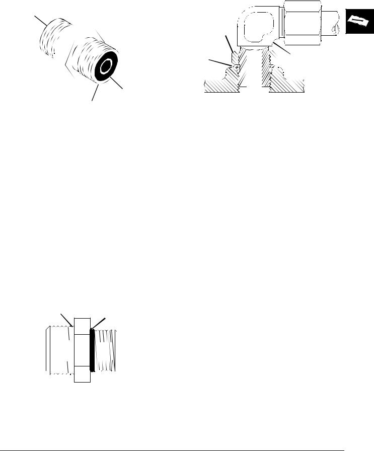
SPECIFICATIONS AND INFORMATION |
O-RING SEAL SERVICE RECOMMENDATIONS |
|
|
|
|
O-RING FACE SEAL FITTINGS |
. |
Sealing Surface
O-ring
Sealing Surface
1.Inspect the fitting sealing surfaces. They must be free of dirt or defects.
2.Inspect the O-ring. It must be free of damage or defects.
3.Lubricate O-rings and install into groove using petroleum jelly to hold in place.
4.Push O-ring into the groove with plenty of petroleum jelly so O-ring is not displaced during assembly.
5.Index angle fittings and tighten by hand pressing joint together to insure O-ring remains in place.
6.Tighten fitting or nut to torque value shown on the chart per dash size stamped on the fitting. Do not allow hoses to twist when tightening fittings.
O-RING BOSS FITTINGS
1.Inspect boss O-ring boss seat. It must be free of dirt and defects. If repeated leaks occur, inspect for defects with a magnifying glass. Some raised defects can be removed with a slip stone.
Groove
O-ring
2.Put hydraulic oil or petroleum jelly on the O-ring. Place electrical tape over the threads to protect O- ring from nicks. Slide O-ring over the tape and into the groove of fitting. Remove tape.
Special Nut
Special Washer |
|
|
|
|
|
|
|
|
Angle Fitting |
|||||||||
|
|
|
|
|
|
|
|
|
|
|
|
|
|
|
|
|
|
|
|
|
|
|
|
|
|
|
|
|
|
|
|
|
|
|
|
|
|
|
|
|
|
|
|
|
|
|
|
|
|
|
|
|
|
|
|
|
|
|
|
|
|
|
|
|
|
|
|
|
|
|
|
|
|
|
|
|
|
|
|
|
|
|
|
|
|
|
|
|
|
|
|
|
|
|
|
|
|
|
|
|
|
|
|
|
|
|
|
|
|
|
|
|
|
3.For angle fittings, loosen special nut and push special washer against threads so O-ring can be installed into the groove of fitting.
4.Turn fitting into the boss by hand until special washer or washer face (straight fitting) contacts boss face and O-ring is squeezed into its seat.
5.To position angle fittings, turn the fitting counterclockwise a maximum of one turn.
6.Tighten straight fittings to torque value shown on chart. For angle fittings, tighten the special nut to value shown in the chart while holding body of fitting with a wrench.
STRAIGHT FITTING OR SPECIAL NUT TORQUE
Thread |
Torquea |
Number |
||
Size |
|
|
of Flatsb |
|
N•m |
lb-ft |
|||
|
|
|||
|
|
|
|
|
|
|
|
|
|
3/8-24 UNF |
8 |
(6) |
2 |
|
|
|
|
|
|
7/16-20 UNF |
12 |
(9) |
2 |
|
|
|
|
|
|
1/2-20 UNF |
16 |
(12) |
2 |
|
|
|
|
|
|
9/16-18 UNF |
24 |
(18) |
2 |
|
|
|
|
|
|
3/4-16 UNF |
46 |
(34) |
2 |
|
|
|
|
|
|
7/8-14 UNF |
62 |
(46) |
1-1/2 |
|
|
|
|
|
|
1-1/16-12 UN |
102 |
(75) |
1 |
|
|
|
|
|
|
1-3/16-12 UN |
122 |
(90) |
1 |
|
|
|
|
|
|
1-5/16-12 UN |
142 |
(105) |
3/4 |
|
|
|
|
|
|
1-5/8-12 UN |
190 |
(140) |
3/4 |
|
|
|
|
|
|
1-7/8-12 UN |
217 |
(160) |
1/2 |
|
|
|
|
|
|
a.Torque tolerance is ± 10 percent.
b.To be used if a torque wrench cannot be used. After tightening fitting by hand, put a mark on nut or boss; then tighten special nut or straight fitting the number of flats shown.
3/20/97 |
2 - 11 |

GASOLINE SPECIFICATIONS |
SPECIFICATIONS AND INFORMATION |
|
|
|
|
GASOLINE SPECIFICATIONS 4–CYCLE ENGINES - NORTH AMERICA
c CAUTION
Gasoline is HIGHLY FLAMMABLE, handle it with care.
DO NOT refuel machine while:
•indoors, always fill gas tank outdoors;
•machine is near an open flame or sparks;
•engine is running, STOP engine;
•engine is hot, allow it to cool sufficiently first;
•smoking.
Help prevent fires:
•fill gas tank to bottom of filler neck only;
•be sure fill cap is tight after fueling;
•clean up any gas spills IMMEDIATELY;
|
|
|
|
|
|
|
|
|
|
|
|
|
|
|
|
|
|
|
|
|
|
|
|
|
|
|
|
|
|
|
|
|
|
|
|
|
|
|
|
|
|
|
|
|
|
|
|
|
|
|
|
|
|
|
|
|
|
|
|
|
|
|
|
|
|
|
|
|
|
|
|
|
|
|
|
|
|
|
|
|
|
|
|
|
|
|
|
|
|
|
|
STOP ENGINE |
|
|
NO HOT ENGINE |
|
|
NO SMOKING |
|||||||||||||||||||||||||||||||||||||||
|
|
|
|
|
|
|
|
|
|
|
|
|
|
|
|
|
|
|
|
|
|
|
|
|
|
|
|
|
|
|
|
|
|
|
|
|
|
|
|
|
|
|
|
|
|
NO OPEN FLAME |
NO STATIC ELECTRIC |
OR SPARK |
DISCHARGE |
•keep machine clean and in good repair–free of excess grease, oil, debris, and faulty or damaged parts;
•any storage of machines with gas left in tank should be in an area that is well ventilated to prevent possible igniting of fumes by an open flame or spark, this includes any appliance with a pilot light.
To prevent fire or explosion caused by STATIC ELECTRIC DISCHARGE during fueling:
•ONLY use a clean, approved POLYETHYLENE PLASTIC fuel container and funnel WITHOUT any metal screen or filter.
To avoid engine damage:
•DO NOT mix oil with gasoline;
•ONLY use clean, fresh unleaded gasoline with an octane rating (anti-knock index) of 87 or higher;
•fill gas tank at the end of each day's operation to help prevent condensation from forming inside a partially filled tank;
•keep up with specified service intervals.
Use of alternative oxygenated, gasohol blended, unleaded gasoline is acceptable as long as:
•the ethyl or grain alcohol blends DO NOT exceed 10% by volume or
•methyl tertiary butyl ether (MTBE) blends DO NOT exceed 15% by volume.
IMPORTANT: DO NOT use METHANOL gasolines because METHANOL is harmful to the environment and to your health.
c WARNING
California Proposition 65 Warning: Gasoline engine exhaust from this product contains chemicals known to the State of California to cause cancer, birth defects, or other reproductive harm.
GASOLINE STORAGE
IMPORTANT: Keep all dirt, scale, water or other foreign material out of gasoline.
Keep gasoline stored in a safe, protected area. Storage of gasoline in a clean, properly marked (“UNLEADED
GASOLINE”) POLYETHYLENE PLASTIC container WITHOUT any metal screen or filter is recommended. DO NOT use de-icers to attempt to remove water from gasoline or depend on fuel filters to remove water from gasoline. Use a water separator installed in the storage tank outlet. BE SURE to properly discard unstable or contaminated gasoline. When storing unit or gasoline, it is recommended that you add John Deere Gasoline Conditioner and Stabilizer (TY15977) or an equivalent to the gasoline. BE SURE to follow directions on container and to properly discard empty container.
2 - 12 |
3/20/97 |
SPECIFICATIONS AND INFORMATION |
GASOLINE SPECIFICATIONS |
|
|
|
|
4–CYCLE ENGINES - EUROPE
c CAUTION
Gasoline is HIGHLY FLAMMABLE, handle it with care.
DO NOT refuel machine while:
•indoors, always fill gas tank outdoors;
•machine is near an open flame or sparks;
•engine is running, STOP engine;
•engine is hot, allow it to cool sufficiently first;
•smoking.
Help prevent fires:
•fill gas tank to bottom of filler neck only;
•be sure fill cap is tight after fueling;
•clean up any gas spills IMMEDIATELY;
|
|
|
|
|
|
|
|
|
|
|
|
|
|
|
|
|
|
|
|
|
|
|
|
|
|
|
|
|
|
|
|
|
|
|
|
|
|
|
|
|
|
|
|
|
|
|
|
|
|
|
|
|
|
|
|
|
|
|
|
|
|
|
|
|
|
|
|
|
|
|
|
|
|
|
|
|
|
|
|
|
|
|
|
|
|
|
|
|
|
|
|
STOP ENGINE |
|
|
NO HOT ENGINE |
|
|
NO SMOKING |
|||||||||||||||||||||||||||||||||||||||
|
|
|
|
|
|
|
|
|
|
|
|
|
|
|
|
|
|
|
|
|
|
|
|
|
|
|
|
|
|
|
|
|
|
|
|
|
|
|
|
|
|
|
|
|
|
NO OPEN FLAME |
NO STATIC ELECTRIC |
• keep machine clean and in good repair–free of excess grease, oil, debris, and faulty or damaged |
|
OR SPARK |
DISCHARGE |
parts;
• any storage of machines with gas left in tank should be in an area that is well ventilated to prevent possible igniting of fumes by an open flame or spark, this includes any appliance with a pilot light.
To prevent fire or explosion caused by STATIC ELECTRIC DISCHARGE during fueling:
•ONLY use a clean, approved POLYETHYLENE PLASTIC fuel container and funnel WITHOUT any metal screen or filter.
To avoid engine damage:
•DO NOT mix oil with gasoline;
•ONLY use clean, fresh unleaded gasoline with an octane rating (anti-knock index) of 87 or higher;
•fill gas tank at the end of each day's operation to help prevent condensation from forming inside a partially filled tank;
•keep up with specified service intervals.
Use of alternative oxygenated, gasohol blended, unleaded gasoline is acceptable as long as:
•the ethyl or grain alcohol blends DO NOT exceed 10% by volume or
•methyl tertiary butyl ether (MTBE) blends DO NOT exceed 15% by volume.
GASOLINE STORAGE
IMPORTANT: Keep all dirt, scale, water or other foreign material out of gasoline.
Keep gasoline stored in a safe, protected area. Storage of gasoline in a clean, properly marked (“UNLEADED
GASOLINE”) POLYETHYLENE PLASTIC container WITHOUT any metal screen or filter is recommended. DO NOT use de-icers to attempt to remove water from gasoline or depend on fuel filters to remove water from gasoline. Use a water separator installed in the storage tank outlet. BE SURE to properly discard unstable or contaminated gasoline. When storing unit or gasoline, it is recommended that you add John Deere Gasoline Conditioner and Stabilizer (TY15977) or an equivalent to the gasoline. BE SURE to follow directions on container and to properly discard empty container.
IMPORTANT: DO NOT use METHANOL gasolines because METHANOL is harmful to the environment and to your health.
3/20/97 |
2 - 13 |
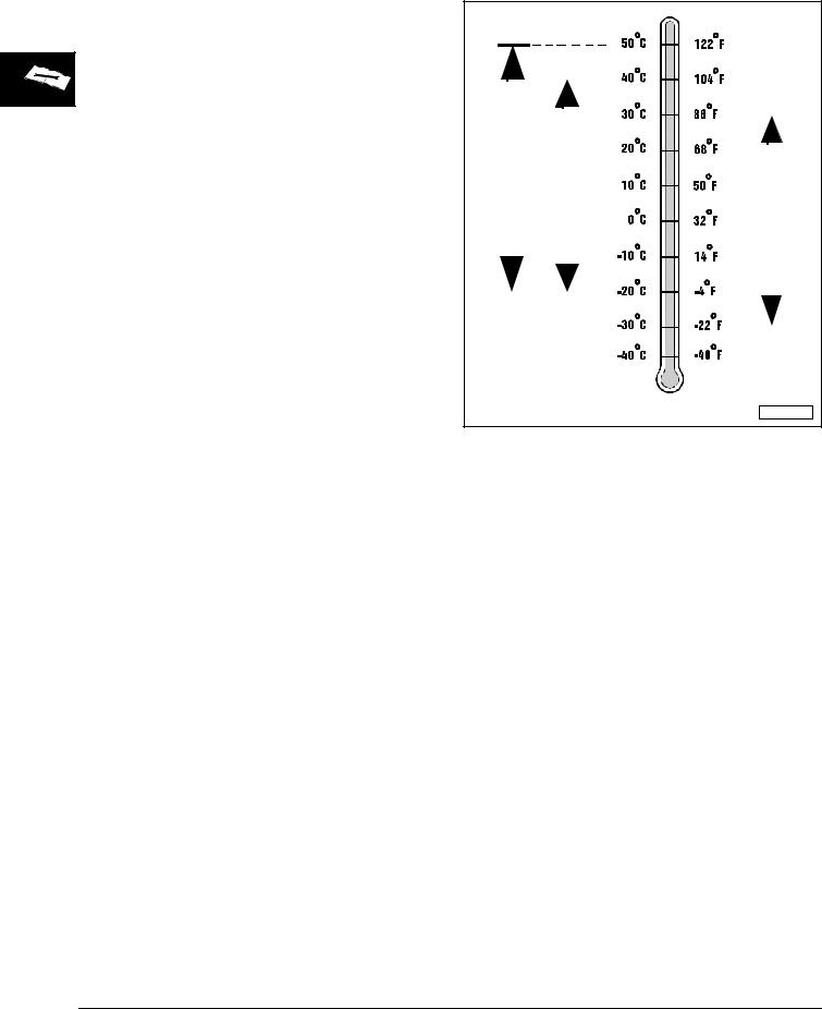
4–CYCLE GASOLINE ENGINE OIL |
SPECIFICATIONS AND INFORMATION |
|
|
|
|
4–CYCLE GASOLINE ENGINE OIL
4–CYCLE GASOLINE ENGINE OIL - |
NORTH AMERICA |
IMPORTANT: Kohler command engines were designed and built to use multi-viscosity oil. Multi-viscosity oil is required for proper operation of hydraulic valve lifters used in Kohler command engines.
Use the appropriate oil viscosity based on the expected air temperature range during the period between recommended oil changes. Operating outside of these recommended oil air temperature ranges may cause premature engine failure.
The following John Deere oils are PREFERRED:
•PLUS–4®—SAE 10W-40;
•TURF–GARD®—SAE 10W-30;
•PLUS–4®—SAE 10W-30 ;
The following John Deere oil is also recommended, based on their specified temperature range:
• TORQ–GARD SUPREME®—SAE 5W-30 .
Other oils may be used if above John Deere oils are not available, provided they meet one of the following specifications:
•SAE 10W-40—API Service Classification SG or higher;
•SAE 10W-30—API Service Classification SG or higher;
•SAE 5W-30—API Service Classification SG or higher.
|
|
|
|
|
|
|
|
|
|
|
|
|
|
|
|
|
|
|
|
|
|
|
|
|
|
|
|
|
|
|
|
|
|
|
|
|
|
|
|
|
|
|
|
|
|
|
|
|
|
|
|
|
|
|
|
|
|
|
|
|
|
|
|
|
|
|
|
|
|
|
|
|
|
|
|
|
|
|
|
|
|
|
|
|
|
|
|
|
|
|
|
|
|
|
SAE 10W-40 |
|
|
|
|
|
|
|
|
|
|
|
|
|
|
|
|
|
|
|
|
|
|
||||||
|
|
|
|
|
|
|
|
|
SAE 10W-30 |
|
|
|
|
|||||||||||||||||
|
|
|
|
|
|
|
|
5W-30 |
||||||||||||||||||||||
|
|
|
|
|
|
|
||||||||||||||||||||||||
|
|
|
|
|
|
|
|
|
|
|
|
|
|
|
|
|
|
|
|
|
|
|
|
|
|
|
|
SAE |
||
|
|
|
|
|
|
|
|
|
|
|
|
|
|
|
|
|
|
|
|
|
|
|
|
|
|
|
|
|
|
|
|
|
|
|
|
|
|
|
|
|
|
|
|
|
|
|
|
|
|
|
|
|
|
|
|
|
|
|
|
|
|
|
|
|
|
|
|
|
|
|
|
|
|
|
|
|
|
|
|
|
|
|
|
|
|
|
|
|
|
|
|
|
|
|
|
|
|
|
|
|
|
|
|
|
|
|
|
|
|
|
|
|
|
|
|
|
|
|
|
|
|
|
|
|
|
|
|
|
|
|
|
|
|
|
|
|
|
|
|
|
|
|
|
|
|
|
|
|
|
|
|
|
|
|
PREFERRED
AIR TEMPERATURE
M58275
John Deere Dealers: You may want to crossreference the following publications to recommend the proper oil for your customers:
•Module DX,ENOIL2 in JDS–G135;
•Section 530, Lubricants & Hydraulics, of the John Deere Merchandise Sales Guide;
•Lubrication Sales Manual PI7032.
2 - 14 |
3/20/97 |
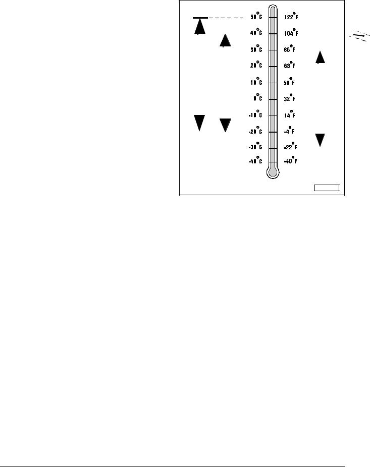
SPECIFICATIONS AND INFORMATION |
4–CYCLE GASOLINE ENGINE OIL |
|
|
|
|
4–CYCLE GASOLINE ENGINE OIL - EUROPE
IMPORTANT: Kohler command engines were designed and built to use multi-viscosity oil. Multi-viscosity oil is required for proper operation of hydraulic valve lifters used in Kohler command engines.
Use the appropriate oil viscosity based on the expected air temperature range during the period between recommended oil changes. Operating outside of these recommended oil air temperature ranges may cause premature engine failure.
The following John Deere oils are PREFERRED:
•TORQ–GARD SUPREME®—SAE 10W-40;
•UNI–GARD™—SAE 10W-40;
•TORQ–GARD SUPREME®—SAE 10W-30;
•UNI–GARD™—SAE 10W-30.
The following John Deere oil is also recommended, based on their specified temperature range:
•TORQ–GARD SUPREME®—SAE 5W-30;
•UNI–GARD™—SAE 5W-30.
Other oils may be used if above John Deere oils are not available, provided they meet one of the following specifications:
• CCMC Specification G4 or higher.
|
|
|
|
|
|
|
|
|
|
|
|
|
|
|
|
|
|
|
|
|
|
|
|
|
|
|
|
|
|
|
|
|
|
|
|
|
|
|
|
|
|
|
|
|
|
|
|
|
|
|
|
|
|
|
|
|
|
|
|
|
|
|
|
|
|
|
|
|
|
|
|
|
|
|
|
|
|
|
|
|
|
|
|
|
|
|
|
|
|
|
|
|
|
|
|
|
|
|
|
|
|
|
|
|
|
|
|
|
|
|
|
|
|
|
|
|
|
|
|
|
|
|
|
|
|
|
|
|
|
SAE 10W-40 |
|
|
|
|
|
|
|
|
|
|
|
|
|
|
|
|
|
|
|
|
|
|
|
||||||
|
|
|
|
|
|
|
|
|
SAE 10W-30 |
|
|
|
|
|
|||||||||||||||||
|
|
|
|
|
|
|
|
5W-30 |
|
||||||||||||||||||||||
|
|
|
|
|
|
|
|||||||||||||||||||||||||
|
|
|
|
|
|
|
|
|
|
|
|
|
|
|
|
|
|
|
|
|
|
|
|
|
|
|
SAE |
|
|||
|
|
|
|
|
|
|
|
|
|
|
|
|
|
|
|
|
|
|
|
|
|
|
|
|
|
|
|
|
|
|
|
|
|
|
|
|
|
|
|
|
|
|
|
|
|
|
|
|
|
|
|
|
|
|
|
|
|
|
|
|
|
|
|
|
|
|
|
|
|
|
|
|
|
|
|
|
|
|
|
|
|
|
|
|
|
|
|
|
|
|
|
|
|
|
|
|
|
|
|
|
|
|
|
|
|
|
|
|
|
|
|
|
|
|
|
|
|
|
|
|
|
|
|
|
|
|
|
|
|
|
|
|
|
|
|
|
|
|
|
|
|
|
|
|
|
|
|
|
|
|
|
|
|
|
|
|
|
|
|
PREFERRED
AIR TEMPERATURE
M58275
John Deere Dealers: You may want to crossreference the following publications to recommend the proper oil for your customers:
•Module DX,ENOIL2 in JDS–G135;
•Section 530, Lubricants & Hydraulics, of the John Deere Merchandise Sales Guide.
3/20/97 |
2 - 15 |
4–CYCLE GASOLINE ENGINE OIL |
SPECIFICATIONS AND INFORMATION |
|
|
|
|
BREAK–IN 4-CYCLE GASOLINE ENGINE OIL - NORTH AMERICA
IMPORTANT: ONLY use a quality break-in oil (multi-viscosity) in rebuilt or remanufactured engines for the first 5 hours (maximum) of operation. DO NOT use oils with heavier viscosity weights than SAE 5W-30 or oils meeting specifications API SG or SH, these oils will not allow rebuilt or remanufactured engines to break-in properly.
The following John Deere oil is PREFERRED:
• BREAK–IN ENGINE OIL .
John Deere BREAK–IN ENGINE OIL is formulated with special additives for aluminum and cast iron type engines to allow the power cylinder components (pistons, rings, and liners as well) to “wear-in” while protecting other engine components, valve train and gears, from abnormal wear. Engine rebuild instructions should be followed closely to determine if special requirements are necessary.
John Deere BREAK–IN ENGINE OIL is also recommended for non-John Deere engines, both aluminum and cast iron types.
The following John Deere oil is also recommended as
abreak-in engine oil:
•TORQ–GARD SUPREME®—SAE 5W-30.
If the above recommended John Deere oils are not available, use a break-in engine oil meeting the following specification during the first 5 hours (maximum) of operation:
•SAE 5W-30—API Service Classification SE or higher.
IMPORTANT: After the break-in period, use the John Deere oil that is recommended for this engine.
|
|
|
|
|
|
|
|
|
|
|
|
|
|
|
|
|
|
|
|
|
|
|
|
|
|
|
|
|
|
|
|
|
|
|
|
|
|
|
|
BREAK-IN OIL |
|
|
|
|
|
|
|
|
|
|
|
|
|
|
|
|
|
|
|
|
|
|
|
|
|
|
|
|
|
|
|
SAE 5W-30 |
|
|
|
|
|
|
|
|
|
|
|
|
|
|
|
|
|
|
|
|
|
|
|
|
|
|
|
|
|
|
|
|
|
|
|
|
|
|
|
|
|
|
|
|
|
|
|
|
|
|
|
|
|
|
|
|
|
|
|
|
|
|
|
|
|
|
|
|
|
|
|
|
|
|
|
|
|
|
|
PREFERRED
AIR TEMPERATURE
M58275
John Deere Dealers: You may want to crossreference the following publications to recommend the proper oil for your customers:
•Module DX,ENOIL4 in JDS–G135;
•Section 530, Lubricants & Hydraulics, of the John Deere Merchandise Sales Guide;
•Lubrication Sales Manual PI7032.
2 - 16 |
3/20/97 |
SPECIFICATIONS AND INFORMATION |
4–CYCLE GASOLINE ENGINE OIL |
|
|
|
|
BREAK–IN 4-CYCLE GASOLINE ENGINE OIL - EUROPE
IMPORTANT: ONLY use a quality break-in oil (multi-viscosity) in rebuilt or remanufactured engines for the first 5 hours (maximum) of operation. DO NOT use oils with heavier viscosity weights than SAE 5W-30 or oils meeting CCMC Specification G5—these oils will not allow rebuilt or remanufactured engines to break-in properly.
The following John Deere oil is PREFERRED:
• BREAK–IN ENGINE OIL .
John Deere BREAK–IN ENGINE OIL is formulated with special additives for aluminum and cast iron type engines to allow the power cylinder components (pistons, rings, and liners as well) to “wear-in” while protecting other engine components, valve train and gears, from abnormal wear. Engine rebuild instructions should be followed closely to determine if special requirements are necessary.
John Deere BREAK–IN ENGINE OIL is also recommended for non-John Deere engines, both aluminum and cast iron types.
The following John Deere oil is also recommended as
abreak-in engine oil:
•TORQ–GARD SUPREME®—SAE 5W-30.
If the above recommended John Deere oils are not available, use a break-in engine oil meeting the following specification during the first 5 hours (maximum) of operation:
• SAE 5W-30—CCMC Specification G4 or higher.
IMPORTANT: After the break-in period, use the John Deere oil that is specified for this engine.
|
|
|
|
|
|
|
|
|
|
|
|
|
|
|
|
|
|
|
|
|
|
|
|
|
|
|
|
|
|
|
|
|
|
|
|
|
|
|
|
|
|
|
|
|
|
|
|
|
|
|
|
|
|
|
|
|
|
|
|
|
|
|
|
|
BREAK-IN OIL |
|
|
|
|
|
|
|
|
|
|
|
|
|
|
|
|
|
|
|
|
|
|
|
|
|
|
|
|
|
|
|
|
|
SAE 5W-30 |
|
||||
|
|
|
|
|
|
|
|
|
|
|
|
|
|
|
|
|
|
|
|
|
|
|
|
|
|
|
|
|
|
|
|
|
|
|
|
|
|
|
|
|
|
|
|
|
|
|
|
|
|
|
|
|
|
|
|
|
|
|
|
|
|
|
|
|
|
|
|
|
|
|
|
|
|
|
|
|
|
|
|
|
|
|
|
PREFERRED
AIR TEMPERATURE
M58275
John Deere Dealers: You may want to crossreference the following publications to recommend the proper oil for your customers:
•Module DX,ENOIL4 in JDS–G135;
•Section 530, Lubricants & Hydraulics, of the John Deere Merchandise Sales Guide.
3/20/97 |
2 - 17 |
HYDROSTATIC TRANSMISSION OIL |
SPECIFICATIONS AND INFORMATION |
|
|
|
|
HYDROSTATIC TRANSMISSION OIL
HYDROSTATIC TRANSMISSION OIL - NORTH AMERICA
Use the following oil viscosity based on the air temperature range. Operating outside of the recommended oil air temperature range may cause premature hydrostatic transmission failure.
IMPORTANT: ONLY use a quality SAE 10W-30 engine oil in this transmission. DO NOT mix any other oils in this transmission. DO NOT use BIO–HY–GARD® in this transmission.
The following John Deere oils are PREFERRED:
•TURF-GARD®—SAE 10W-30;
•PLUS-4®—SAE 10W-30.
Other oils may be used if above recommended John Deere oils are not available, provided they meet one of the following specifications:
• API Service Classification SG or higher.
SAE 10W-30
|
|
|
|
|
|
|
|
|
|
|
|
|
|
|
|
|
|
|
|
|
|
|
|
|
|
|
|
|
|
|
|
|
|
|
|
|
|
AIR TEMPERATURE |
M58275 |
John Deere Dealers: You may want to crossreference the following publications to recommend the proper oil for your customers:
•Module DX,ENOIL2 in JDS–G135;
•Section 530, Lubricants & Hydraulics, of the John Deere Merchandise Sales Guide;
•Lubrication Sales Manual PI7032.
2 - 18 |
3/20/97 |
SPECIFICATIONS AND INFORMATION |
HYDROSTATIC TRANSMISSION OIL |
|
|
|
|
HYDROSTATIC TRANSMISSION OIL - EUROPE
Use the following oil viscosity based on the air temperature range. Operating outside of the recommended oil air temperature range may cause premature hydrostatic transmission failure.
IMPORTANT: ONLY use a quality SAE 10W-30 engine oil in this transmission. DO NOT mix any other oils in this transmission. DO NOT use BIO–HY–GARD® in this transmission.
The following John Deere oil is PREFERRED:
• TORQ-GARD SUPREME®—SAE 10W-30.
Other oils may be used if above recommended John Deere oils are not available, provided they meet one of the following specifications:
• CCMC Specification G4 or higher.
SAE 10W-30
|
|
|
|
|
|
|
|
|
|
|
|
|
|
|
|
|
|
|
|
|
|
|
|
|
|
|
|
|
|
|
|
|
|
|
|
|
|
AIR TEMPERATURE |
M58275 |
|
|
|
John Deere Dealers: You may want to crossreference the following publications to recommend the proper oil for your customers:
•Module DX,ENOIL2 in JDS–G135;
•Section 530, Lubricants & Hydraulics, of the John
Deere Merchandise Sales Guide.
3/20/97 |
2 - 19 |

ALTERNATIVE LUBRICANTS |
SPECIFICATIONS AND INFORMATION |
|
|
|
|
ALTERNATIVE LUBRICANTS
Conditions in certain geographical areas outside the United States and Canada may require different lubricant recommendations than the ones printed in this technical manual or the operator's manual. Consult with your John Deere Dealer, or Sales Branch, to obtain the alternative lubricant recommendations.
IMPORTANT: Use of alternative lubricants could cause reduced life of the component.
If alternative lubricants are to be used, it is recommended that the factory fill be thoroughly removed before switching to any alternative lubricant.
SYNTHETIC LUBRICANTS
Synthetic lubricants may be used in John Deere equipment if they meet the applicable performance requirements (industry classification and/or military specification) as shown in this manual.
The recommended air temperature limits and service or lubricant change intervals should be maintained as shown in the operator’s manual.
Avoid mixing different brands, grades, or types of oil. Oil manufacturers blend additives in their oils to meet certain specifications and performance requirements. Mixing different oils can interfere with the proper functioning of these additives and degrade lubricant performance.
LUBRICANT STORAGE
All machines operate at top efficiency only when clean lubricants are used. Use clean storage containers to handle all lubricants. Store them in an area protected from dust, moisture, and other contamination. Store drums on their sides. Make sure all containers are properly marked as to their contents. Dispose of all old, used containers and their contents properly.
MIXING OF LUBRICANTS
In general, avoid mixing different brands or types of lubricants. Manufacturers blend additives in their lubricants to meet certain specifications and performance requirements. Mixing different lubricants can interfere with the proper functioning of these additives and lubricant properties which will downgrade their intended specified performance.
OIL FILTERS
IMPORTANT: Filtration of oils is critical to proper lubrication performance. Always change filters regularly.
The following John Deere oil filters are PREFERRED:
•AUTOMOTIVE AND LIGHT TRUCK ENGINE OIL FILTERS.
Most John Deere filters contain pressure relief and anti-drainback valves for better engine protection.
Other oil filters may be used if above recommended John Deere oil filters are not available, provided they meet the following specification:
• ASTB Tested In Accordance With SAE J806.
John Deere Dealers: You may want to crossreference the following publications to recommend the proper oil filter for your customers:
•Module DX,FILT in JDS–G135;
•Section 540, Lubricants & Hydraulics, of the John Deere Merchandise Sales Guide;
•Lawn & Grounds Care Tune-Up Guide PI672.
2 - 20 |
3/20/97 |
SPECIFICATIONS AND INFORMATION |
GEAR TRANSMISSION GREASE |
|
|
|
|
GEAR TRANSMISSION GREASE
Use the following gear grease based on the air temperature range. Operating outside of the recommended grease air temperature range may cause premature gear transmission failure.
IMPORTANT: ONLY use these specified greases in this transmission. DO NOT mix any other greases in this transmission. DO NOT use any BIO–GREASE in this transmission.
ONLY use the following PREFERRED grease as the input shaft needle bearing lubricant:
• Unirex N3 Grease®—M120263.
Other greases may be used as the input shaft needle bearing lubricant if they meet or exceed the following specification:
• ASTM D–1743, NLGI Grade 1.
ONLY use the following PREFERRED grease as the gear housing lubricant:
• Shell Darina D Grease®—AM119608.
Other greases may be used as the gear housing lubricant if they meet or exceed the following specification:
• ASTM D–1743, NLGI Grade 1.
|
|
|
|
|
|
|
|
|
|
|
|
|
|
|
|
|
|
|
|
|
|
|
|
|
|
|
|
|
|
|
|
|
|
|
|
|
|
|
|
|
|
|
|
ASTM D–1743 |
NLGI Grade 1 |
|
||||||||
|
|
|
|
|
|
|
|
|
|
|
|
|
|
|
|
|
|
|
|
|
|
|
|
|
|
|
|
|
|
|
|
|
AIR TEMPERATURE |
M58275 |
John Deere Dealers: You may want to crossreference the following publications to recommend the proper grease for your customers:
•Module DX,GREA1 in JDS–G135;
•Section 530, Lubricants & Hydraulics, of the John Deere Merchandise Sales Guide;
•Lubrication Sales Manual PI7032.
3/20/97 |
2 - 21 |

ANTI-CORROSION GREASE SPECIFICATIONS |
SPECIFICATIONS AND INFORMATION |
|
|
|
|
ANTI-CORROSION GREASE
SPECIFICATIONS
This anti-corrosion grease is formulated to provide the best protection against absorbing moisture, which is one of the major causes of corrosion. This grease is also superior in its resistance to separation and migration.
The following anti-corrosion grease is PREFERRED:
•DuBois MPG-2® Multi-Purpose Polymer Grease—M79292.
Other greases may be used if they meet or exceed the following specifications:
• John Deere Standard JDM J13A2, NLGI Grade 1.
|
|
|
|
|
|
J13A2 |
Grade 1 |
||
|
JDM |
NLGI |
||
|
|
|
|
|
|
|
|
|
|
|
|
|
|
|
AIR TEMPERATURE |
M58275 |
John Deere Dealers: You may want to crossreference the following publications to recommend the proper grease for your customers:
•Module DX,GREA1 in JDS–G135;
•Section 530, Lubricants & Hydraulics, of the John Deere Merchandise Sales Guide;
•Lubrication Sales Manual PI7032.
2 - 22 |
3/20/97 |
 Loading...