


O P E R A T O R ’ S |
M A N U A L |
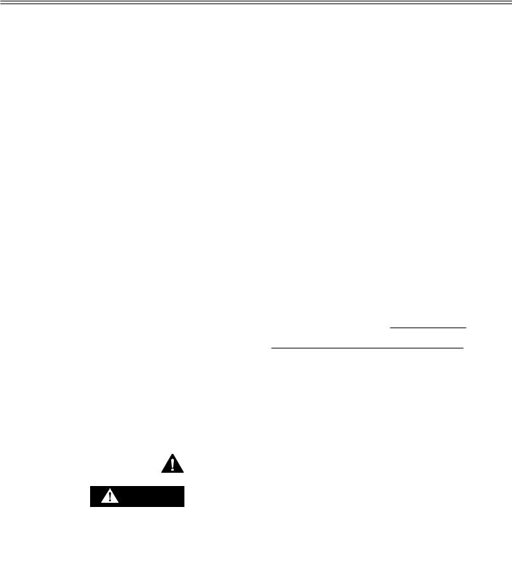
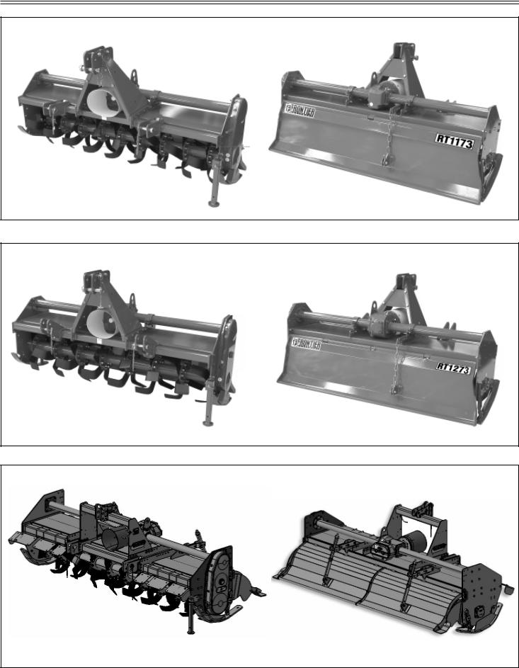
ROTARY TILLERS
|
RT 1173 |
|
|
RT 1273 |
|
|
RT 2293 |
|||
|
RT 1181 |
|
|
RT 2283 |
|
|
|
|||
|
|
|
|
|
|
|||||
|
|
|
|
|
|
|
|
|
|
|
|
|
|
|
|
|
|
|
|
|
|
|
|
|
|
|
|
|
|
|
|
|
|
|
|
|
|
|
|
|
|
|
|
Cod. F07010857 / Rev. 00 (2011-04)
THIS MANUAL IS ALSO APPLICABLE TO FRONTIER TILLERS WITH MODEL NUMBERS ENDING IN A ‘C’.

TABLE OF CONTENTS
Technical specification |
|
Tilling tips .................................................... |
20 |
Technical specification ................................ |
4 |
During tilling ................................................ |
20 |
Technical specification - Hitch ..................... |
6 |
Replacement parts ...................................... |
20 |
Safety signs |
|
Safety-Alert simbol ...................................... |
7 |
Identification machine ................................. |
7 |
Machine safety labels.................................. |
7 |
Service Machine Safely |
|
Practice safe maintenance .......................... |
21 |
Wear appropriate clothing ........................... |
21 |
Stay clear of rotating drivelines ................... |
21 |
Machine safety labels and positions |
|
Machine safety labels and positions ........... |
8 |
Preparing the vehicle |
|
Preparing the tractor ................................... |
10 |
Park vehicle safety ...................................... |
10 |
Stay clear of rotating drivelines ................... |
10 |
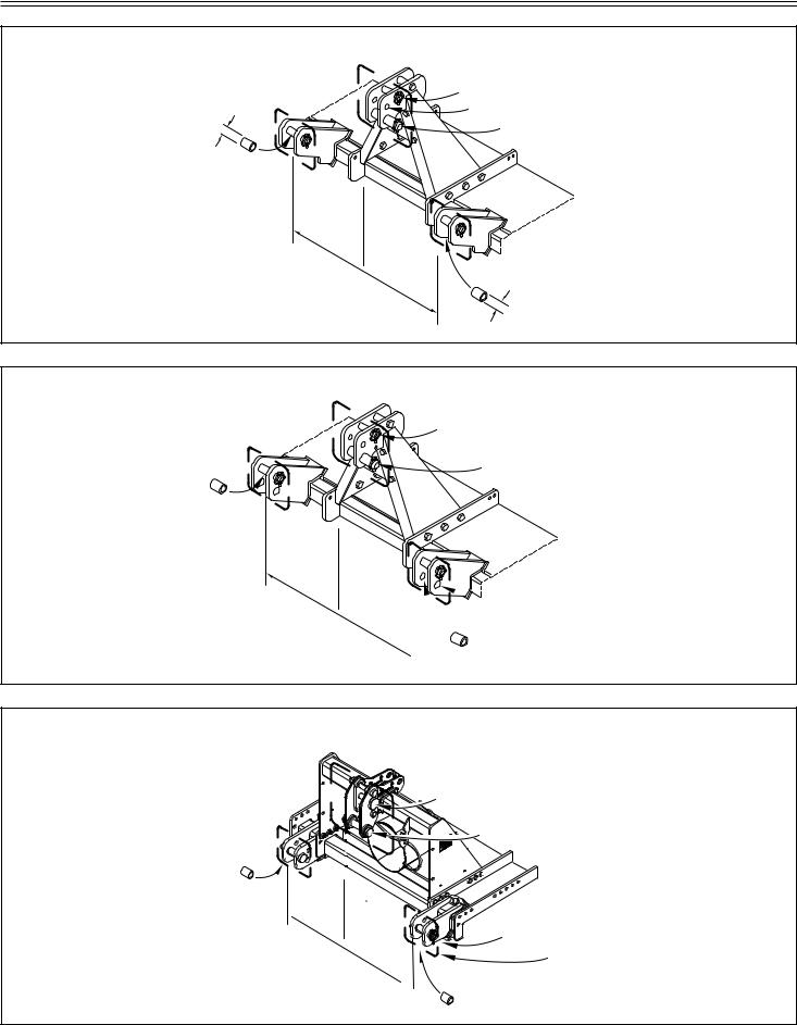
Installing |
|
Installing tiller on tractor .............................. |
10 |
PTO shaft .................................................... |
12 |
PTO shaft with clutch .................................. |
13 |
Quick Coupler (optional) ............................. |
14 |
Park vehicle safety ...................................... |
14 |
Stay clear of rotating drivelines ................... |
14 |
Removing |
|
Removing tiller ............................................ |
15 |
Removing tiller with Quick Coupler ............. |
15 |
Operating |
|
Operate safely ............................................. |
16 |
Wear appropriate clothing ........................... |
17 |
Stay clear of rotating drivelines ................... |
17 |
Raising parking stand.................................. |
17 |
Lowering parking stand ............................... |
17 |
Levelling attachments (side-to-side) ........... |
17 |
Levelling tiller (front-to-rear) ........................ |
18 |
Adjusting skid shoes ................................... |
18 |
Adjusting levelling board ............................. |
18 |
Spring ram....................................................... |
19 |
Change speed ............................................. |
19 |
Service lubrication |
|
Service lubrication ....................................... |
22 |
Every 8 work hours ..................................... |
22 |
Every 50 work hours ................................... |
22 |
Every 400 work hours ................................. |
22 |
Every 1000 work hours ............................... |
22 |
Greasing and lubricant points ..................... |
23 |
Lubricants ................................................... |
23 |
Screw tighteening torques........................... |
23 |
Service |
|
Chain stretcher ............................................ |
24 |
Service intervals .......................................... |
24 |
Replacing tines ........................................... |
24 |
Tines ........................................................... |
24 |
Troubleshooting |
|
Using troubleshooting chart ........................ |
25 |
Storing machine |
|
Storing tiller ................................................. |
26 |
Removing tiller from storage ....................... |
26 |
Assembly / Spare parts |
|
RT 1173-1181-1273-2283-2293 ........................ |
27 |
Lift hook assembly procedure ..................... |
29 |
Installing driveline on tiller ........................... |
29 |
Spare parts.................................................. |
29 |
TO THE DEALER:
Assembly and proper installation of this product is the responsibility of the Frontier dealer. Read manual instruction and safety rules. Make sure all items on the Dealer’s Pre-Delivery Check List in the Operator’s Manual are completed before releasing equipment to the owner.
The dealer must complete the Warranty Registration, located on the Frontier website. Warranty claims will be denied if the Warranty Registration has not been completed.
TO THE OWNER:
Read this manual before operating your frontier equipment. The information presented will prepare you to do a better and a safer job. Keep this manual handy for ready reference. Require all operators to read this manual carefully and become acquainted with all the adjustment and operating procedures before attempting to operate. Replacement manuals can be obtained from your selling dealer.
The equipment you have purchased has been carefully enginereed and manufactured to provide dependable and satisfactory use. Like all mechanical products, it will require cleaning and upkeep. Lubricate the unit as specified. Observe all safety information in this manual and safety decals on the equipment.
For service, your authorized Frontier dealer has trained mechanics, genuine Frontier service parts, and the necessary tools and equipment to handle all your needs.
Use only genuine Frontier service parts.Substitute parts will void the warranty and may not meet standards required for safe and satisfactory operation. Record the model number and serial number of your equipment in the spaces provided:
Model: |
|
Date of Purchase |
Serial Number: (see Safety Decal section for location)
Provide this information to your dealer to obtain correct repair parts.
Throghout this manual, the term IMPORTANT is used to indicate that failure to observe can cause damage to equipment. The terms CAUTION, WARNING and DANGER are used in conjunction with the Safety-Alert Symbol, (a triangle with an esclamation mark), to indicate the degree of hazard for items of personal safety.
DANGER
 WARNING
 CAUTION
IMPORTANT NOTE
This Safety-Alert Simbol indicates a hazard and means ATTENTION! BECOME ALERT! YOUR SAFETY IS INVOLVED!
Indicates an imminently hazardous situation that, if not avoided, will result in death or serious injury.
Indicates a potentially hazardous situation that, if not avoided, could result in death or serious injury, and includes hazards that are exposed when guards are removed.
Indicates a potentially hazardous situation that, if not avoided, may result in minor or moderate injury.
Indicates that a failure to observe can cause damage to equipment.
Indicates helpful information.
Cod. F07010857 / Rev. 00 (2011-03)
TECHNICAL SPECIFICATIONS
RT 1173 - 1181
RT 1273
RT 2283 - 2293
Technical specifications - Page 4

TECHNICAL SPECIFICATIONS
RT 1173 - 1181
Model |
Work/width |
Tractor HP |
Tractor HP |
Weight |
Side |
PTO |
Speeds |
Input |
Hitch |
Tines |
Rotor |
Rotor |
|
inches |
min |
max |
lbs. |
Drive |
shaft |
gear box |
speed |
|
STD |
blades |
flanges |
|
|
|
|
|
|
|
|
|
|
|
|
|
|
|
|
|
|
Chain |
Slip |
|
|
Cat. “II” |
|
|
|
RT 1173 |
73 |
45 |
60 |
761 |
ASA |
Clutch |
Single |
540 |
Quick |
“C” |
6 |
10 |
|
|
|
|
|
100 |
|
|
|
coupler |
|
|
|
|
|
|
|
|
|
|
|
|
|
|
|
|
|
|
|
|
|
Chain |
Slip |
|
|
Cat. “II” |
|
|
|
RT 1181 |
81 |
50 |
60 |
810 |
ASA |
Clutch |
Single |
540 |
Quick |
“C” |
6 |
11 |
|
|
|
|
|
100 |
|
|
|
coupler |
|
|
|
RT 1273
Model |
Work/width |
Tractor HP |
Tractor HP |
Weight |
Side |
PTO |
Speeds |
Input |
Hitch |
Tines |
Rotor |
Rotor |
|
inches |
min |
max |
lbs. |
Drive |
shaft |
gear box |
speed |
|
STD |
blades |
flanges |
|
|
|
|
|
|
Slip |
|
|
Cat. “II” |
|
|
|
RT 1273 |
73 |
30-70 |
80 |
968 |
Gear |
Clutch |
Single |
540 |
Quick |
“L” |
6 |
7 |
|
|
|
|
|
|
|
|
|
coupler |
|
|
|
|
|
|
|
|
|
|
|
|
|
|
|
|
RT 2283 - 2293
Model |
Work/width |
Tractor HP |
Tractor HP |
Weight |
Side |
PTO |
Speeds |
Input |
Hitch |
Tines |
Rotor |
Rotor |
|
inches |
min |
max |
lbs. |
Drive |
shaft |
gear box |
speed |
|
STD |
blades |
flanges |
|
|
|
|
|
|
|
|
|
|
|
|
|
|
|
|
|
|
|
|
|
|
Cat. ”II” |
|
|
|
RT 2283 |
83 |
30-70 |
80 |
1397 |
Gear |
Slip |
Multi |
540 |
Quick |
“L” |
6 |
8 |
|
|
|
|
|
|
Clutch |
|
|
coupler |
|
|
|
|
|
|
|
|
|
|
|
|
|
|
|
|
|
|
|
|
|
|
|
|
|
Cat. ”II” |
|
|
|
RT 2293 |
93 |
40-80 |
100 |
1496 |
Gear |
Slip |
Multi |
540 |
Quick |
“L” |
6 |
9 |
|
|
|
|
|
|
Clutch |
|
|
coupler |
|
|
|
|
|
|
|
|
|
|
|
|
|
|
|
|
Technical specifications - Page 5
TECHNICAL SPECIFICATIONS - HITCH
RT 1173 - 1181: Cat. «I» Standard and iMatch Quick Hitch; Cat. «II» Standard and Quick Coupler
|
Cat. II Std pin Ø mm 25 (inch 0.984) |
|
Cat. I Std pin Ø mm 19 (inch 0.748) |
¯ |
Cat. II Quick Coupler pin Ø mm 32 (inch 1.26) |
Cat. I iMatch Quick Hitch Ø mm 32 (inch 1.26) |
|
= |
|
|
|
mm |
823 |
|
|
mm |
|
|
|
- |
||
|
|
683 |
|
Without bushings: Cat. «I» Standard |
|
-inch |
|
|
|
|
inch |
Cat. «II» Standard bushings Ø = 28 (inch 1.1)
Cat. «I» iMatch Quick Hitch bushings Ø = 36,5 (inch 1.44) Cat. «II» Quick Coupler bushings Ø = 36,5 (inch 1.44)
= |
|
|
32,4 |
cat. |
|
26,8 |
||
2 |
||
|
cat. |
|
|
1 |
¯
RT 1273 : Cat. «II» Standard and Quick Coupler
= |
|
|
mm |
823 |
|
|
|
|
|
- |
|
|
|
inch |
= 32,4
cat.2
Cat. II Std pin Ø mm 25 (inch 0.984)
Cat. II Quick Coupler pin Ø mm 32 (inch 1.26)
 Without bushings: Cat. «II» Standard
 With bushings: Cat. «II» Quick Coupler
RT 2283 - 2293 : Cat. «II» Standard and Quick Coupler
Cat. II Std pin Ø mm 25 (inch 0.984)
Cat. II Quick Coupler pin Ø mm 32 (inch 1.26)
Without bushings: Cat. «II» Standard With bushings: Cat. «II» Quick Coupler
= |
|
|
mm |
823 |
|
|
- |
|
|
|
inch |
= 32,4
cat.2
Without bushings: Cat. «II» Standard
With bushings: Cat. «II» Quick Coupler
Technical specifications - Hitch - Page 6
SAFETY SIGNS
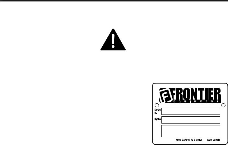
Safety-alert symbol
Read and recognize safety information.
Be alert to the potential for personal injury when you see this safety-alert symbol.
On your machine safety labels, the words DANGER, WARNING, and CAUTION are used with safetyalert symbol.
DANGER identifies the most serious hazards. In this manual, the word CAUTION and this symbol call attention to safety messages.
Identification machine
Identification plate machine
Machine safety labels
1) WARNING: AVOID INJURY FROM ROTATING KNIVES:
• Keep hands, feet and clothing away.
2) WARNING: AVOID INJURY FROM PTO:
•Keep all shields in place. Keep hands, feet and clothing away.
•Operate only with 540 RPM.
3)CAUTION: AVOID INJURY
•Read Operator’s Manual
•Ballast power unit per operator’s manual
•Know location and function of controls
•Keep all shields in place
•Stay clear of power driven parts
•Never carry riders
•Keep people and pets a safe distance away from machine
BEFORE DISMOUNTING OR SERVICING
•Shut off engine and remove key
•Lock brake for park
•Lower or block up machine
4)DANGER: ROTATING DRIVELINE - CONTACT CAN CAUSE DEATH - KEEP AWAY! - DO NOT OPERATE WITHOUT:
•All driveline, tractor and equipment shields in place
•Drivelines securely attached at both ends
•Drivelines shields that turn freely on driveline.
5)DANGER: SHIELD MISSING DO NOT OPERATE
Picture Note: Separate telescoping driveshaft members to locate safety label. Label attached to outer profile tube.
Safety Signs - Page 7

MACHINE SAFETY LABELS AND POSITIONS
RT 1173 - 1181
1 |
3 |
|
2 |
||
|
1
RT 1273
1 |
3 |
|
2 |
||
|
1
RT 2283 - 2293
1
3
2
1
4
5
1
2
3
|
|
|
|
|
|
|
|
|
|
|
|
|
|
|
|
|
|
|
|
|
|
|
|
|
|
|
|
|
|
|
|
|
|
|
|
|
|
|
|
|
|
|
|
|
|
|
|
|
4 |
|
|
5 |
|
|
|
Safety Signs - Page 8
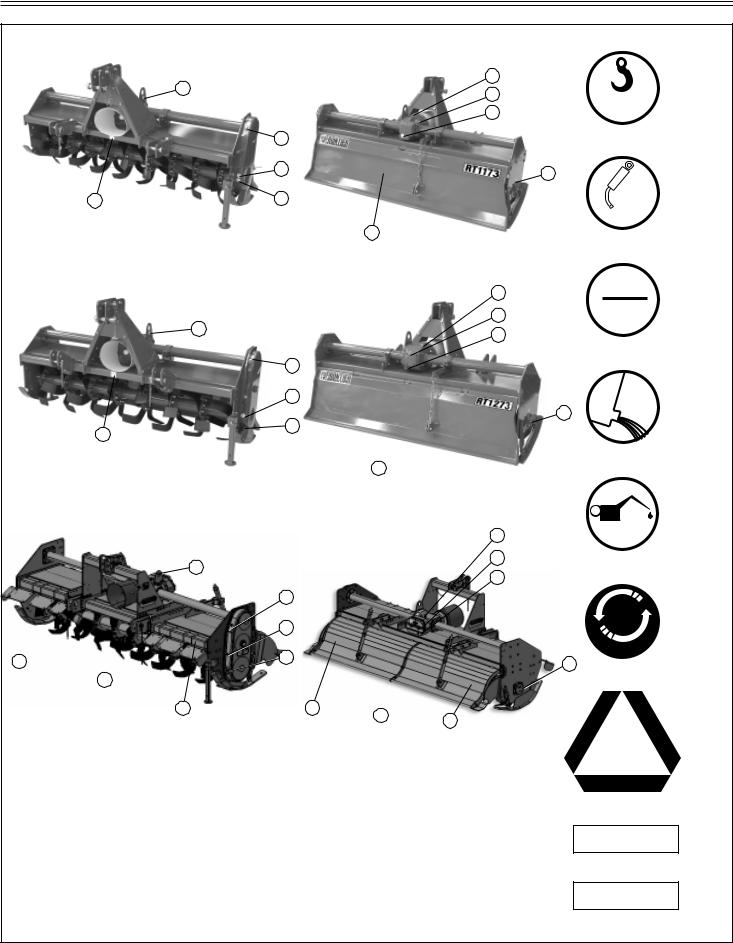
MACHINE SAFETY LABELS AND POSITIONS
RT 1173 - 1181
6 |
|
|
|
10 |
|
|
|
8 |
|
|
|
|
|
|
|
|
|
|
9 |
|
|
10 |
|
|
|
|
8 |
|
|
11 |
|
9 |
|
|
|
|
|
12 |
|
|
|
RT 1273 |
|
|
|
|
|
|
10 |
|
6 |
|
|
8 |
|
|
|
9 |
|
|
|
|
|
|
|
|
10 |
|
|
|
|
8 |
|
|
11 |
|
9 |
|
|
|
|
|
|
|
|
|
|
12 |
|
|
|
RT 2283 - 2293 |
|
10 |
|
|
|
|
|
|
6 |
|
|
8 |
|
|
|
9 |
|
|
|
|
|
|
|
|
10 |
|
|
|
|
8 |
|
|
14 |
|
9 |
|
|
|
|
|
|
|
11 |
|
|
|
|
14 |
|
13 |
12 |
13 |
|
|
|
||
|
|
|
|
6)Coupling point for lifting (indicating the maximun capacity)
7)Greasing point / Oil fill and level plugs
8)Oil level plug
9)Oil drain plug
10)Oil fill plug
11)Number of revolutions of power takeoff
12)Warning, slow machine
13)Red strip (only for model: 2293)
14)Amber strip (only for model: 2293)
MAX
Kg...
6
7
GREASE
7
OIL
LEVEL
8
OIL
7
9
OIL
10
540  MAX
MAX
7 11
12
23456789012345678901234
23456789012345678901234
23456789012345678901234
23456789012345678901234
23456789012345678901234
234567890123456789012345
13
234567890123456
23456789012345 6
23456789012345 6
23456789012345 6
14
Safety Signs - Page 9
 Loading...