


 Loading...
John Deere AutoTrac™
Controller—Raven™
OPERATOR'S MANUAL
John Deere AutoTrac™
Controller—Raven™
OMPFP11320 ISSUE H1 (ENGLISH)
CALIFORNIA
Proposition 65 Warning
Diesel engine exhaust and some of its constituents are known to the State of California to cause cancer, birth defects, and other reproductive harm.
If this product contains a gasoline engine:
 WARNING
The engine exhaust from this product contains chemicals known to the State of California to cause cancer, birth defects or other reproductive harm.
The State of California requires the above two warnings.
Additional Proposition 65 Warnings can be found in this manual.
John Deere Ag Management Solutions
Worldwide Edition
DCY
OMPFP11320
PRINTED IN U.S.A.

Introduction
www.StellarSupport.com
NOTE: Product functionality may not be fully represented in this document due to product changes occurring after the time of printing. Read the latest Operator's Manual and Quick Reference Guide prior to operation. To obtain a copy, see your dealer or visit www.StellarSupport.com
OUO6050,0000FB1 -19-10AUG10-1/1
Foreword
This AutoTrac Controller Operator's Manual is to be used with the Guidance Operator's Manual.
READ BOTH MANUALS carefully to learn how to operate and service your system correctly. Failure to do so could
result in personal injury or equipment damage. These manuals may also be available in other languages. (See your John Deere dealer to order.)
JS56696,0000A39 -19-14JUN11-1/1
090811
PN=2

Contents
|
Page |
Safety |
|
Recognize Safety Information ............................ |
05-1 |
Understand Signal Words................................... |
05-1 |
Follow Safety Instructions................................... |
05-1 |
Practice Safe Maintenance................................. |
05-2 |
Handle Electronic Components and |
|
Brackets Safely .............................................. |
05-2 |
Use Seat Belt Properly ....................................... |
05-3 |
Operate Guidance Systems Safely .................... |
05-3 |
Use AutoTrac Controller on Approved Vehicles .. |
05-3 |
Safety Signs |
|
Automatic Guidance System Detected............... |
10-1 |
AutoTrac Controller |
|
AutoTrac Accuracy ............................................. |
15-1 |
General Information............................................ |
15-1 |
AutoTrac Settings ............................................... |
15-2 |
Activity Monitor ................................................... |
15-2 |
AutoTrac Controller Troubleshooting |
|
AutoTrac Controller ............................................ |
20-1 |
Diagnostic Readings........................................... |
20-2 |
Stop Codes......................................................... |
20-3 |
AutoTrac Controller—Raven |
|
AutoTrac Controller— Raven Calibration ........... |
25-1 |
Failed Calibrations.............................................. |
25-8 |
Necessary Conditions for Activating AutoTrac ... |
25-9 |
AutoTrac Controller—Raven |
|
Diagnostic Addresses .................................. |
25-10 |
AutoTrac Controller—Raven |
|
Diagnostic Trouble Codes............................ |
25-12 |
GS2 Display 1800 |
|
Automatic Guidance System Detected............... |
30-1 |
Enabling System................................................. |
30-1 |
Activating System............................................... |
30-1 |
GreenStar Run Page.......................................... |
30-2 |
Enabling AutoTrac .............................................. |
30-6 |
AutoTrac Status Pie............................................ |
30-7 |
Reactivating AutoTrac on Next Pass.................. |
30-8 |
Deactivating AutoTrac ........................................ |
30-8 |
Guidance Settings .............................................. |
30-9 |
AutoTrac Settings ............................................. |
30-10 |
Advanced AutoTrac Settings ............................ |
30-13 |
StarFire ............................................................ |
30-16 |
|
Page |
Troubleshooting—GS2 Display 1800 |
|
Trouble Codes .................................................... |
35-1 |
Diagnostic Addresses......................................... |
35-1 |
Guidance Alarms................................................ |
35-3 |
AutoTrac Deactivation Message......................... |
35-4 |
Diagnostic Addresses......................................... |
35-5 |
GS3 2630 Display |
|
Automatic Guidance System Detected............... |
40-1 |
Enabling System................................................. |
40-2 |
Activating System............................................... |
40-3 |
Deactivating System........................................... |
40-3 |
Setup .................................................................. |
40-4 |
StarFire .............................................................. |
40-5 |
GS3 2630 Advanced Settings |
|
Tuning Recommendations.................................. |
45-1 |
Recommended Tuning Settings ......................... |
45-3 |
Optimizing AutoTrac Controller Performance..... |
45-4 |
Tuning Tips, Tricks, and Precautions.................. |
45-9 |
Troubleshooting.................................................. |
45-9 |
Specifications |
|
Unified Inch Bolt and Screw Torque Values........ |
50-1 |
Metric Bolt and Screw Torque Values................. |
50-2 |
EC Declaration of Conformity............................. |
50-3 |
Original Instructions. All information, illustrations and specifications in this manual are based on the latest information available at the time of publication. The right is reserved to make changes at any time without notice.
COPYRIGHT © 2011
DEERE & COMPANY
Moline, Illinois
All rights reserved.
A John Deere ILLUSTRUCTION ® Manual
i
090811
PN=1

Contents
ii
090811
PN=2
Safety
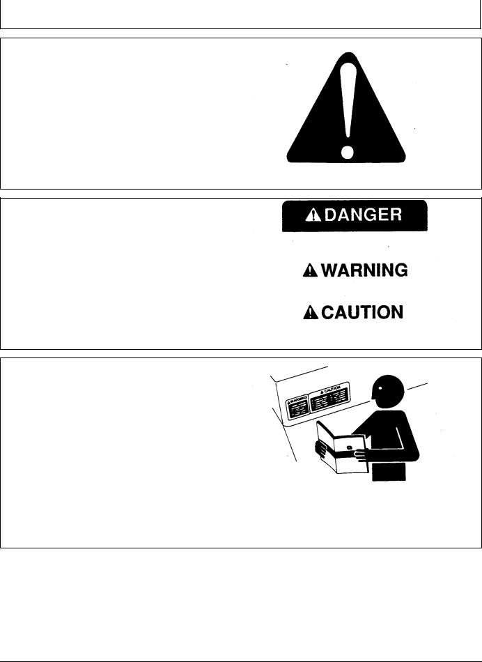
Recognize Safety Information
This is a safety-alert symbol. When you see this symbol on your machine or in this manual, be alert to the potential for personal injury.
Follow recommended precautions and safe operating practices.
Understand Signal Words
A signal word—DANGER, WARNING, or CAUTION—is used with the safety-alert symbol. DANGER identifies the most serious hazards.
DANGER or WARNING safety signs are located near specific hazards. General precautions are listed on CAUTION safety signs. CAUTION also calls attention to safety messages in this manual.
T81389 —UN—07DEC88
DX,ALERT -19-29SEP98-1/1
TS187 —19—30SEP88
DX,SIGNAL -19-03MAR93-1/1
Follow Safety Instructions
Carefully read all safety messages in this manual and on your machine safety signs. Keep safety signs in good condition. Replace missing or damaged safety signs. Be sure new equipment components and repair parts include the current safety signs. Replacement safety signs are available from your John Deere dealer.
There can be additional safety information contained on parts and components sourced from suppliers that is not reproduced in this operator's manual.
Learn how to operate the machine and how to use controls properly. Do not let anyone operate without instruction.
Keep your machine in proper working condition. Unauthorized modifications to the machine may impair the function and/or safety and affect machine life.
TS201 —UN—23AUG88
If you do not understand any part of this manual and need assistance, contact your John Deere dealer.
DX,READ -19-16JUN09-1/1
05-1 |
PN=5 |
|
090811 |
Safety
Practice Safe Maintenance
Understand service procedure before doing work. Keep area clean and dry.
Never lubricate, service, or adjust machine while it is moving. Keep hands, feet , and clothing from power-driven parts. Disengage all power and operate controls to relieve pressure. Lower equipment to the ground. Stop the engine. Remove the key. Allow machine to cool.
Securely support any machine elements that must be raised for service work.
Keep all parts in good condition and properly installed. Fix damage immediately. Replace worn or broken parts. Remove any buildup of grease, oil, or debris.
On self-propelled equipment, disconnect battery ground cable (-) before making adjustments on electrical systems or welding on machine.
On towed implements, disconnect wiring harnesses from tractor before servicing electrical system components or welding on machine.
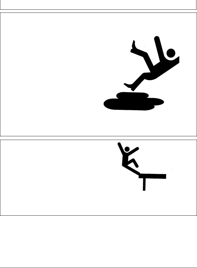
Handle Electronic Components and Brackets
Safely
Falling while installing or removing electronic components mounted on equipment can cause serious injury. Use a ladder or platform to easily reach each mounting location. Use sturdy and secure footholds and handholds. Do not install or remove components in wet or icy conditions.
If installing or servicing a RTK base station on a tower or other tall structure, use a certified climber.
If installing or servicing a global positioning receiver mast used on an implement, use proper lifting techniques and wear proper protective equipment. The mast is heavy and can be awkward to handle. Two people are required when mounting locations are not accessible from the ground or from a service platform.
TS218 —UN—23AUG88
DX,SERV -19-17FEB99-1/1
TS249 —UN—23AUG88
DX,WW,RECEIVER -19-24AUG10-1/1
05-2 |
PN=6 |
|
090811 |

Safety
Use Seat Belt Properly
Use a seat belt when you operate with a roll-over protective structure (ROPS) or cab to minimize chance of injury from an accident such as an overturn.
Do not use a seat belt if operating without a ROPS or cab. |
—UN—23AUG88 |
|
Inspect seat belt and mounting hardware at least |
||
Replace entire seat belt if mounting hardware, buckle, |
|
|
belt, or retractor show signs of damage. |
|
|
once a year. Look for signs of loose hardware or belt |
TS205 |
|
damage, such as cuts, fraying, extreme or unusual wear, |
||
discoloration, or abrasion. Replace only with replacement |
|
|
parts approved for your machine. See your John Deere |
|
|
dealer. |
|
|
|
DX,ROPS1 -19-29OCT07-1/1 |
|
|
|
|
|
|
|
Operate Guidance Systems Safely |
• Never get on or off a moving vehicle. |
|
Do not use guidance systems on roadways. Always turn |
• Verify the machine, implement, and guidance system |
|
are set up correctly. If using iTEC Pro, verify accurate |
||
off (disable) guidance systems before entering a roadway. |
||
boundaries have been defined. |
||
Do not attempt to turn on (activate) a guidance system |
||
• Remain alert and pay attention to the surrounding |
||
while transporting on a roadway. |
environment. |
|
Guidance systems are intended to aid the operator in |
• Take control of the steering wheel, when necessary, to |
|
performing field operations more efficiently. The operator |
avoid field hazards, bystanders, equipment, or other |
|
is always responsible for the machine path. |
obstacles. |
|
Guidance Systems include any application that automates |
• Stop operation if poor visibility conditions impair your |
|
ability to operate the machine or identify people or |
||
vehicle steering. This includes, but may not be limited to, |
obstacles in the machine path. |
|
AutoTrac, iGuide, iTEC Pro, ATU, and RowSense. |
• Consider field conditions, visibility, and vehicle |
|
To prevent injury to the operator and bystanders: |
configuration when selecting vehicle speed. |
|
|
||
|
JS56696,0000970 -19-10MAY11-1/1 |
|
|
||
|
||
Use AutoTrac Controller on Approved Vehicles |
||
Use AutoTrac Controller only on Approved Vehicles—see |
will receive a time-out warning 15 seconds before |
|
StellarSupport.Deere.com for list of approved vehicles |
AutoTrac deactivates. Pressing the resume will reset |
|
activity monitor timer.
When activity monitor is selected, AutoTrac Controller looks for operator activity every seven minutes. Operator
JS56696,0000615 -19-14JUN11-1/1
05-3 |
PN=7 |
|
090811 |
Safety Signs
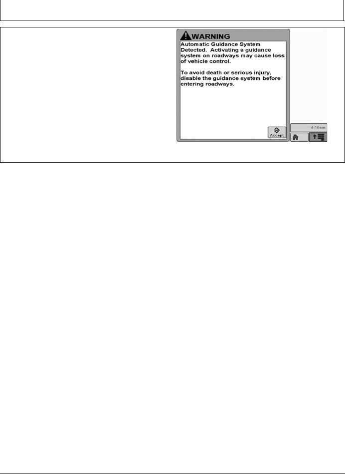
Automatic Guidance System Detected
This message occurs during startup on vehicles with
AutoTrac installed.
The master switch removes power from the EH Valve to prevent AutoTrac from being unintentionally activated. The master switch is intended for use on roadways or when the operator does not want AutoTrac able to be activated.
Ensure AutoTrac is disabled by turning the Master Switch to the OFF position.
PC13157 —19—17FEB11
Automatic Guidance
JS56696,0000A3B -19-14JUN11-1/1
10-1 |
PN=8 |
|
090811 |

AutoTrac Controller |
|
||
|
|
|
|
AutoTrac Accuracy |
• Implement is setup to run properly (wear parts such |
|
|
IMPORTANT: The John Deere AutoTrac system relies |
|
as shanks, shovels, and sweeps are in good working |
|
|
condition and correctly spaced). |
|
|
on the GPS system operated by the government |
• |
|
|
Understand how field/soil conditions affect system |
|
||
of the United States, which is solely responsible |
|
||
(loose soil requires more steering than firm soil, but firm |
|
||
for its accuracy and maintenance. The system |
|
|
|
|
soil can cause uneven draft loads). |
|
|
is subject to changes that could affect accuracy |
|
|
|
|
|
|
|
and performance of all GPS equipment. |
IMPORTANT: Although AutoTrac system can be |
|
|
The overall AutoTrac system accuracy is dependent upon |
|
activated when SF2 (or SF1 if using AutoTrac |
|
|
SF1 activation) correction signal is confirmed, |
|
|
many variables. The equation looks like: |
|
system accuracy may continue to increase |
|
AutoTrac System Accuracy = Signal accuracy + Vehicle |
|
after powering up system. |
|
|
|
|
|
Setup + Implement Setup + Field/Soil Conditions. |
AutoTrac SF2 activation will operate on a SF1, SF2, or |
|
|
It is very important to remember: |
RTK signal. |
|
|
• Receiver has to go through a warm-up period after |
AutoTrac SF1 activation will operate on a SF1 signal only. |
|
|
starting. |
|
|
|
• Vehicle is setup properly (ballasted according to vehicle |
|
|
|
operator manual, etc.) |
|
|
|
CF86321,00002B7 -19-05AUG11-1/1
General Information
All operators must be familiar with AutoTrac system and operating characteristics prior to operation. Operator must know the make of the AutoTrac controller installed on their machine prior to operation.The following is a suggested procedure for operator to become familiar with system:
1.Read and understand Operators Manual for GreenStar Guidance—Parallel Tracking and AutoTrac Assisted Steering Systems.
2.Choose an open area free of hazards (ditches, buildings, etc.).
3.Set Track Spacing to 92.0 meters (300 ft).
4.Set a Track 0 (A—B Line).
NOTE: Operate vehicle at a speed you are comfortable, recommend less than 8 km/h (5 mph).
5.Enable AutoTrac on display by turning Steer ON.
6.Press Resume switch to activate AutoTrac. (See Activating system later in this section).
7.After driving a short distance, then turn steering wheel to turn vehicle off track to deactivate AutoTrac. (See Deactivating System later in this section).
8.Practice Activating AutoTrac at different distances before and after crossing track and at different angles. Increase and decrease speeds to simulate different operating conditions.
9.Reduce Track Spacing to acquire multiple tracks and continue practicing activating AutoTrac at different angles and varying speeds to understand how AutoTrac behaves under different conditions.
Always be prepared to resume manual control if AutoTrac does not perform expected maneuvers or machine course must be changed to avoid injury or property damage.
Operator can regain manual steering by turning steering wheel or Disabling AutoTrac by turning Steer off on display. It is recommended practice to be as close as possible to desired track prior to activating AutoTrac. This will ensure correct track and direction are acquired.
The AutoTrac basic system is intended to be used as an assistance tool to mechanical markers on planters. Operator must evaluate overall system accuracy to determine specific field operations where assisted steering may be used. This evaluation is necessary because accuracy required for various field operations may differ depending on farming operation. Because AutoTrac uses StarFire differential correction network along with Global Positioning System (GPS), slight shifts in position may occur over time.
To operate AutoTrac operator must set track 0 (similar to parallel tracking) and all tracks are drawn parallel to track 0 using track spacing.
The AutoTrac system operating status can exist at four levels: INSTALLED, CONFIGURED, ENABLED, and ACTIVATED.
After enabling AutoTrac (see Enabling AutoTrac), AutoTrac is activated by pressing resume switch on armrest (see Activating AutoTrac). To return to
manual steering, operator must deactivate system (see Deactivating System).
If required track can be shifted left, right or centered using shift track feature on display. (See Shift Track).
CF86321,00002B8 -19-17MAY11-1/1
15-1 |
PN=9 |
|
090811 |
|
AutoTrac Controller |
|
|
|
|
|
|
|
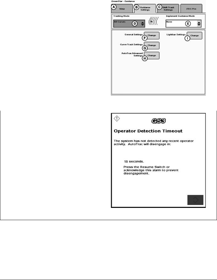
AutoTrac Settings |
|
|
A—View Tab |
F—General Settings |
|
B—Guidance Settings Tab |
G—Curve Track Settings |
|
C—Shift Track Settings |
H—AutoTrac Advanced |
|
D—Tracking Mode |
Settings |
|
E—Implement Guidance Mode |
I— Lightbar Settings |
|
|
|
PC13709 —UN—13MAY11 |
|
|
Guidance Settings |
|
|
CF86321,00002B9 -19-17MAY11-1/1 |
|
|
|
|
|
|
Activity Monitor |
|
|
NOTE: Activity Monitor will only operate if the seat switch |
|
|
is not operational or not installed on the machine. |
|
|
Operator Detection Timeout |
|
|
The system has not detected any recent operator activity. |
|
|
AutoTrac will deactivate in: 15 seconds. |
|
|
Press the Resume Switch or acknowledge this alarm to |
|
|
prevent deactivation. |
|
|
The Activity Monitor will monitor the status of the operator |
|
|
by requiring the operator to provide input to the display |
—UN—20JUL11 |
|
click the Enter button on the pop-up screen. |
||
every 7 minutes. |
|
|
To reset the Activity Monitor, push the resume switch or |
|
|
|
|
PC13872 |
|
|
Operator Detection Timeout |
BA31779,0000232 -19-20JUL11-1/1
15-2 |
PN=10 |
|
090811 |
AutoTrac Controller Troubleshooting
AutoTrac Controller
Symptom |
Problem |
Solution |
AutoTrac Controller won’t activate. |
Stop Code encountered |
See list of stop codes to find issue |
AutoTrac will not resume. |
|
|
AutoTrac Controller does not |
System not recognizing AutoTrac |
Ensure AutoTrac Controller is |
appear on INFO or SETUP screens |
Controller on CAN bus line |
connected to GreenStar Harness and |
|
|
receiving power |
|
|
Check for blown fuses in AutoTrac |
|
|
Controller wiring harness |
Direction can not be determined |
Old TCM Software |
Update TCM Software to newest |
|
|
software (Version 1.08 or greater) |
|
No differential Correction |
Establish differential correction |
|
No GPS |
Establish signal |
|
AutoTrac Controller did not establish |
Drive forward at a speed greater than |
|
direction correctly |
1.6 km/h (1 mph) and turn steering |
|
|
wheel greater than 45 degrees in one |
|
|
direction |
Tractor acquires guidance line but |
AutoTrac Controller has encountered |
tracks 25 to 518 cm (10 to 204 in.) |
a bad wheel angle sensor calibration |
to right or left of line. |
and has an incorrect wheel angle |
|
sensor bias. |
Direction Change Toggle
If the direction of travel is determined to be incorrect, Select the View Tab (A) then select Direction Change Toggle Button (B) to change the displayed direction of travel.
Recalibrate wheel angle sensor and reacquire line to ensure problem is corrected.
A—View Tab |
B—Direction Change Toggle |
|
Button |
PC13566 —UN—04MAY11
Home Screen
CF86321,000035D -19-23MAY11-1/1
20-1 |
PN=11 |
|
090811 |

AutoTrac Controller Troubleshooting
Diagnostic Readings
PC13826 —UN—28JUN11
GreenStar Diagnostic Readings
A—View Drop-Down Menu |
F—Total Hours |
K—Wheel Angle Sensor Type |
P—WAS Calibration Complete |
B—Software Version |
G—AutoTrac Hours |
L—WAS Calibration |
Status |
C—Hardware Part Number |
H—Resume Switch Status |
M—Left WAS Calibration Number |
Q—Valve Calibration |
D—Serial Number |
I— Seat Switch Status |
N—Right WAS Calibration |
R—Left Valve Calibration Number |
E—Mode Status |
J— Stop Code |
Number |
S—Right Valve Calibration |
|
|
O—Center WAS Calibration |
Number |
|
|
Number |
T—Valve Calibration Complete |
|
|
|
Status |
Read the latest Operator Manual prior to operation.
To obtain a copy, see your dealer or visit
www.StellarSupport.com.
CF86321,000035E -19-28JUN11-1/1
20-2 |
PN=12 |
|
090811 |

AutoTrac Controller Troubleshooting
Stop Codes
Stop Code |
Description |
Solution |
None |
Nothing has been checked yet |
|
|
|
|
Steering Wheel |
Steering wheel has moved to deactivate AutoTrac |
Press resume switch to re-activate |
|
|
AutoTrac |
Too Slow |
Vehicle speed too slow to use AutoTrac |
Increase speed over 0.5 km/h (0.3 mph) |
|
|
|
Too Fast |
Vehicle Speed too high to use AutoTrac |
Reduce Speed below platform limit |
|
|
Tractor - 30 km/h (18.6 mph) |
|
|
Sprayer - 37 km/h (23 mph) |
|
|
Harvester - 22 km/h (13.7 mph) |
|
|
Reverse speed on all machines – 10 km/h |
|
|
(6 mph) |
Unknown Direction |
Unknown direction |
Drive forward greater than 1.6 km/h (1 |
|
|
mph) and turn steering wheel greater than |
|
|
45° |
Track Changed |
Track number changed |
Align vehicle on desired track and press |
|
|
resume |
Lost Dual GPS |
SF1, SF2, or RTK signal was lost |
Establish signal |
|
|
|
Steer Control Fault |
A steering control fault severe enough to disable |
Cycle tractor power |
|
AutoTrac |
|
OK |
Last state upgrade was successful |
|
|
|
|
PT Turned Off |
Tracking not turned on. |
Turn tracking on in Setup - Tracking |
|
|
|
Heading Error |
Heading error is out of range. |
Align tractor within heading limit (80° of |
|
|
track) |
Lateral Error |
Lateral error is out of range. |
Align tractor within lateral limit (40% of |
|
|
track spacing) |
No Operator |
Operator presence switch is open. |
Operator in seat or press resume for |
|
|
activity monitor to reset time |
No TCM |
Either no TCM present or TCM is turned off. |
Turn TCM on, or install TCM |
|
|
|
Voltage Unstable |
Voltage Too Low |
Check harnessing |
Reverse Timeout |
Reverse Timeout (greater than 45 seconds) |
Cycle direction forward before resuming |
|
|
in reverse |
0 Speed Timeout |
0 Speed Timeout |
Increase speed over 0.5 km/h (0.3 mph) |
|
|
|
Curvature |
Curve Track radius tighter than AutoTrac will allow |
Manually drive through tight radius curves |
|
|
|
Tracking on Line |
Vehicle is driving on line |
|
Acquiring Line |
Vehicle is acquiring line |
|
CF86321,000035F -19-28JUN11-1/1
20-3 |
PN=13 |
|
090811 |
AutoTrac Controller—Raven
AutoTrac Controller— Raven Calibration
IMPORTANT: John Deere 2600 Display will not operate with AutoTrac Controller—Raven™
NOTE: Calibration procedure must be completed with a passing status prior to using AutoTrac.
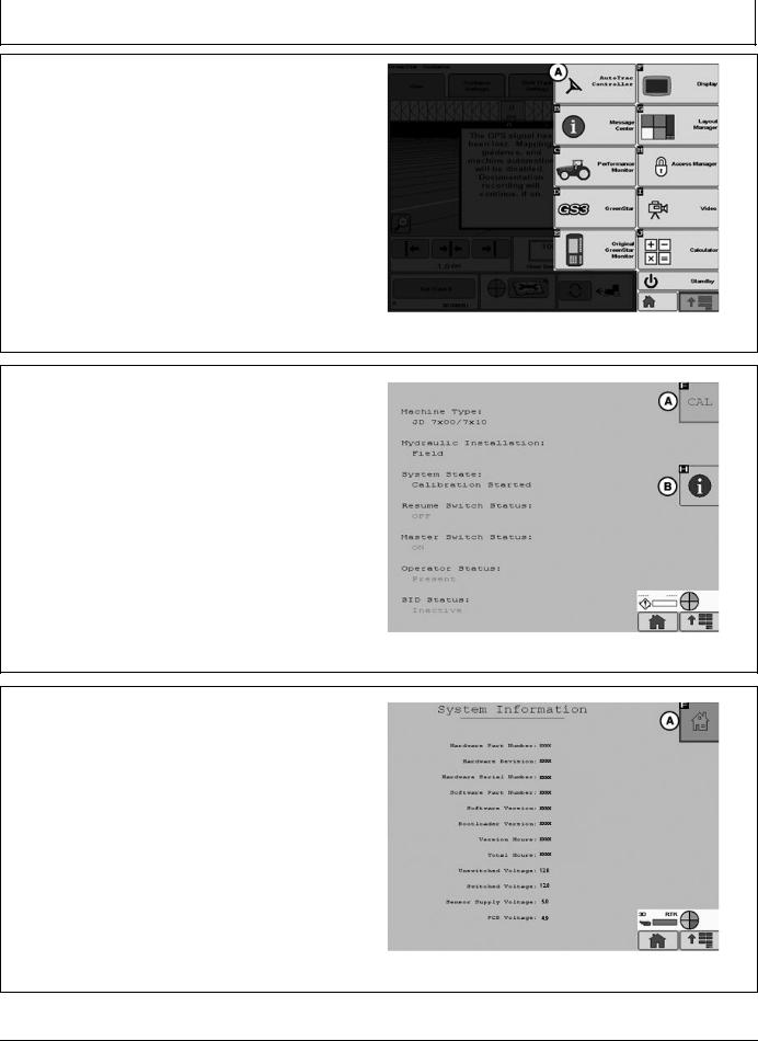
From the Main Menu select AutoTrac Controller.
A—AutoTrac Controller
AutoTrac Main Screen will appear.
In the AutoTrac main screen select the CAL button (A). The Calibration Assistant main screen will appear.
A—Calibration Button |
B—Information Button |
Select the System Information button (B). This will display information to inform the operator that AutoTrac is ready for calibration. Some information is software version and operating voltages. If there are no voltages make sure to check all connections.
After all information is verified select the AutoTrac home button (A) in the upper right of the screen. This will navigate back to the AutoTrac main screen.
A—Home Button
Continued on next page
PC13382 —UN—20JUL11
AutoTrac Button
BA31779,0000223 -19-04AUG11-1/21
PC13383 —UN—20APR11
AutoTrac Main Screen
BA31779,0000223 -19-04AUG11-2/21
PC13384 —UN—19MAY11
System Information
BA31779,0000223 -19-04AUG11-3/21
25-1 |
PN=14 |
|
090811 |
AutoTrac Controller—Raven
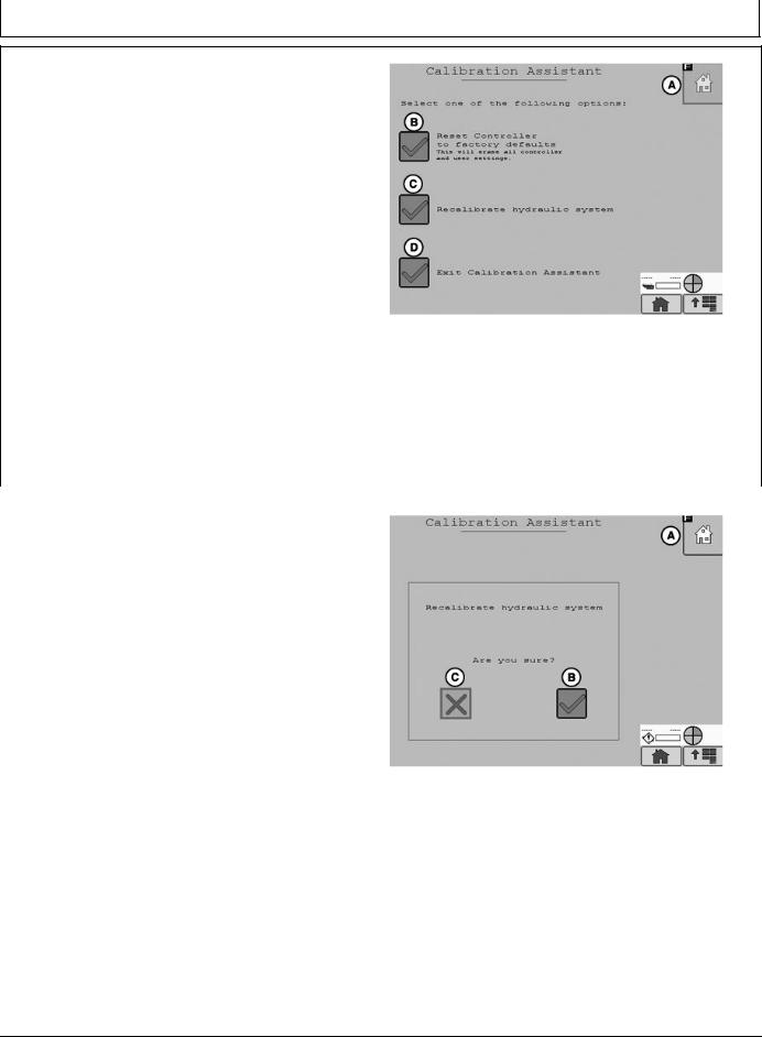
IMPORTANT: Read all instructions before calibrating the AutoTrac Controller
AutoTrac calibration should completed without an implement connected to the tractor to avoid damage to the tractor or implement.
• Drive tractor slowly at full throttle for approximately
2 to 5 minutes to bring hydraulic fluid to operating |
|
temperature before beginning calibration procedure. |
—UN—20APR11 |
• Calibration procedure will require a large, open, level |
|
surface to complete the required steps. |
PC13385 |
• Calibration procedure must be completed prior to using |
|
AutoTrac for the first time. |
|
• Calibration procedure must be complete with a passing |
Calibration Assistant Main Screen |
|
|
status prior to using AutoTrac. If a passing status is not |
|
achieved then AutoTrac will not work. |
A—Home |
C—Recalibrate Hydraulic |
|
NOTE: At any time during calibration, the operator |
B—Reset controller to Factory |
System |
|
Defaults |
D—Exit Calibration Assistant |
||
may take control of the system by grabbing the |
|
|
|
steering wheel or stopping the machine. |
|
|
|
To begin calibration select Recalibrate Hydraulic System |
|
|
|
button (C) form the Calibration Assistant Main screen. |
|
|
|
|
|
|
BA31779,0000223 -19-04AUG11-4/21 |
|
|
|
|
|
|
|
|
To proceed with the calibration process select yes (B) to |
|
|
|
proceed or select no (C) to cancel. |
|
|
|
A—Home |
C—No |
|
|
B—Yes |
|
|
|
|
|
|
PC13387 —UN—20APR11 |
|
|
Recalibrate Hydraulic System |
|
|
|
Continued on next page |
BA31779,0000223 -19-04AUG11-5/21 |
|
|
|
|
25-2 |
PN=15 |
|
090811 |
AutoTrac Controller—Raven
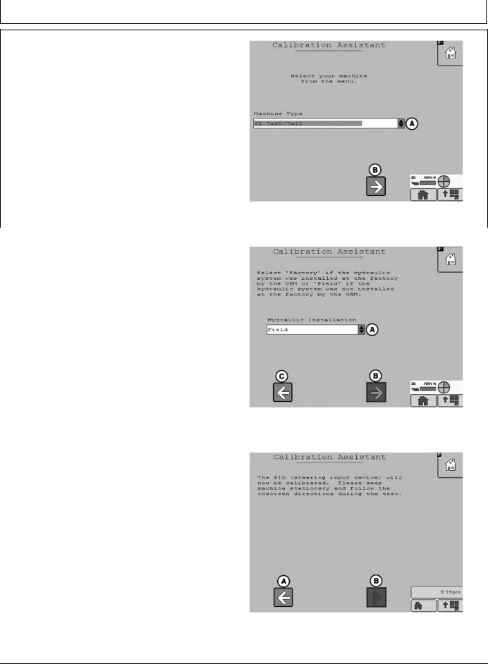
Select the machine type from the drop down menu (A) then select the Next Button (B).
A—Drop Down Menu |
B—Next |
|
|
|
PC13388 —UN—20APR11 |
|
|
Machine Type |
|
|
BA31779,0000223 -19-04AUG11-6/21 |
|
|
|
|
|
|
Select Kit type from the drop down menu (A). If the Kit was |
|
|
installed by the factory select Factory, if it was not installed |
|
|
at the factory select Field. Select Next (B) to proceed, |
|
|
select previous (C) to return to the Machine Type screen. |
|
|
A—Drop Down Menu |
C—Previous |
|
B—Next |
|
|
|
|
PC13389 —UN—20APR11 |
|
|
Kit Type |
|
|
BA31779,0000223 -19-04AUG11-7/21 |
|
|
|
|
|
|
Select Start (B) to calibrate the SID (steering input device). |
|
|
Select Previous to return to the Kit Type screen. |
|
|
A—Previous |
B—Start |
|
|
|
PC13390 —UN—28JUL11 |
|
|
SID Calibration |
|
Continued on next page |
BA31779,0000223 -19-04AUG11-8/21 |
|
|
|
25-3 |
PN=16 |
|
090811 |
AutoTrac Controller—Raven
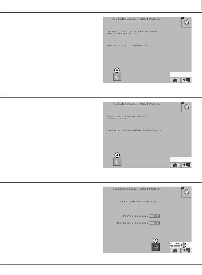
SID will start calibration. Do not touch the steering wheel until instructed. AutoTrac will perform a static pressure test .
A—Previous
PC13391 —UN—20APR11
SID Calibration
BA31779,0000223 -19-04AUG11-9/21
When instructed turn the steering wheel at a normal rate.
AutoTrac will perform a Active Pressure test.
NOTE: Turning the steering wheel too fast or too slow will cause an inaccurate calibration and may cause undesired AutoTrac performance.
PC13394 —UN—20APR11
Differential Pressure Test
BA31779,0000223 -19-04AUG11-10/21
When the Active pressure test is complete the SID Calibration Complete screen will appear. Select Next (A) to proceed to the Resume Switch Status screen.
A—Next
|
PC13395 —UN—20APR11 |
|
SID Calibration Complete |
Continued on next page |
BA31779,0000223 -19-04AUG11-11/21 |
25-4 |
PN=17 |
|
090811 |
AutoTrac Controller—Raven
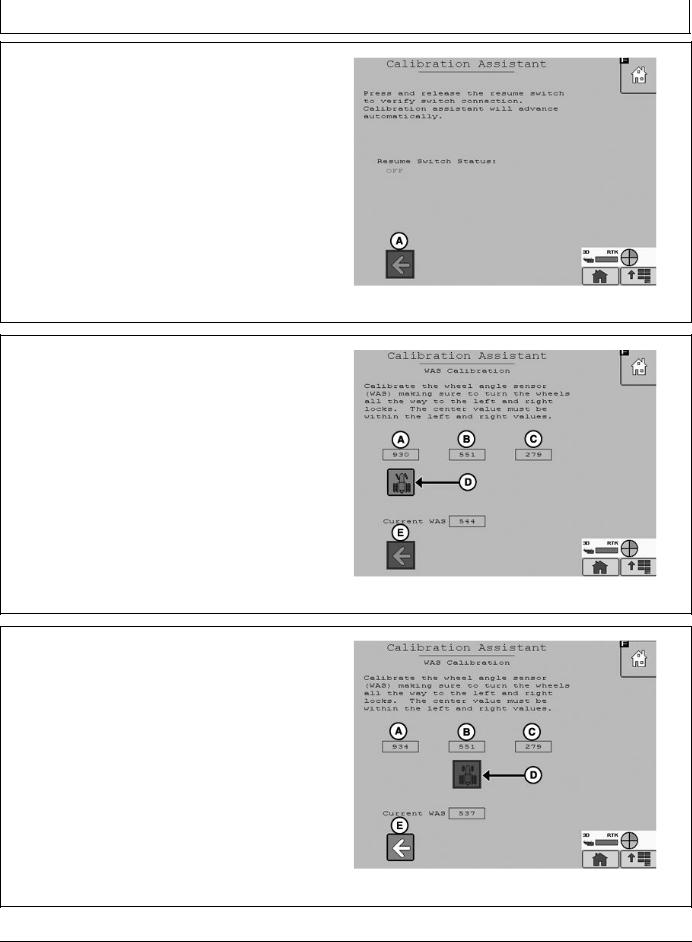
Press and release the resume switch. The red “OFF” text will change to green “ON” text when the button is pressed and back to red “OFF” text when the button is released.
When successful the screen will change to the WAS (Wheel Angle Sensor) Calibration screen.
Select previous to return to SID calibration.
A—Previous
PC13396 —UN—20APR11
Resume Switch Status
BA31779,0000223 -19-04AUG11-12/21
NOTE: It is important that the wheels are turned all of the way to the left and right during the WAS Calibration or undesired AutoTrac operation may occur.
Turn the steering wheel left all the way to the wheels stops and select the tractor icon (D). Selecting the tractor icon will make the icon move under the WAS Center Value (B).
A—WAS Left Value |
D—Tractor Icon |
B—WAS Center Value |
E—Previous |
C—WAS Right Value |
|
NOTE: An accurate center WAS calibration is critical to have desired AutoTrac operation. Driving a short distance looking down the center of the hood and turning your wheels so that you drive straight to a fixed point on the horizon maybe required.
Turn the steering wheel so the wheels are pointing straight forward and select the tractor icon (D). Selecting the tractor icon will make the icon move under the WAS Right Value (C). Selecting previous will make the tractor icon move under the WAS Left Value (A) allowing the operator to change the WAS Left Value.
A—WAS Left Value |
D—Tractor Icon |
B—WAS Center Value |
E—Previous |
C—WAS Right Value |
|
Continued on next page
PC13397 —UN—20APR11
WAS Calibration Left
BA31779,0000223 -19-04AUG11-13/21
PC13398 —UN—20APR11
WAS Calibration Center
BA31779,0000223 -19-04AUG11-14/21
25-5 |
PN=18 |
|
090811 |
AutoTrac Controller—Raven
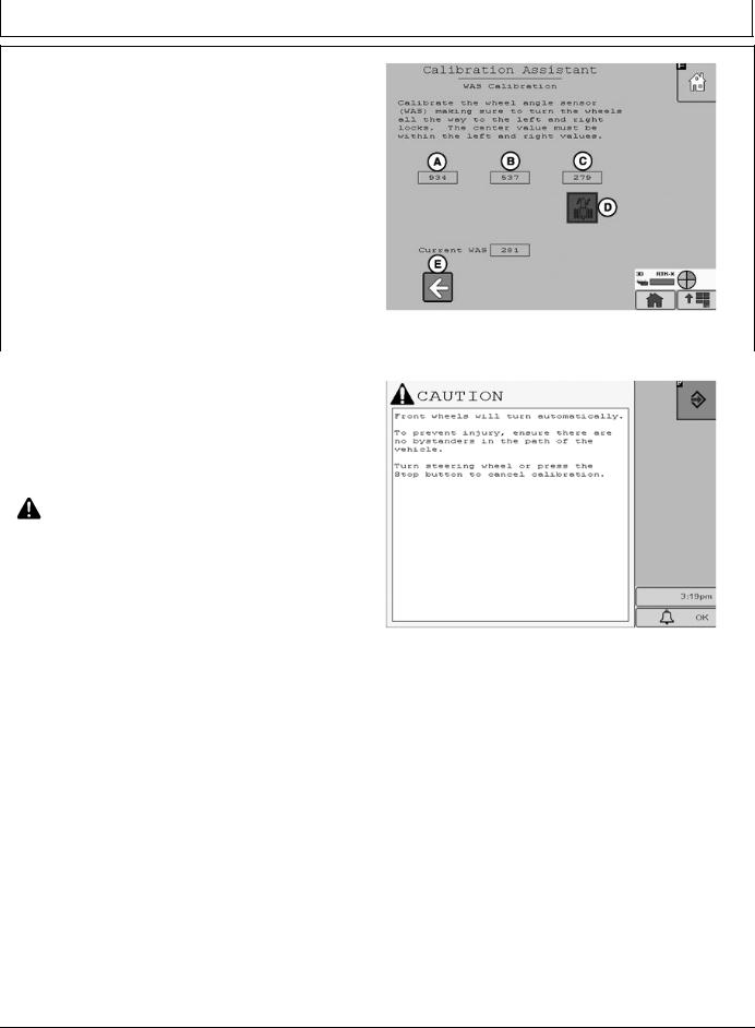
Turn the steering wheel all the way to the right wheel stops and select the tractor icon (D). Selecting the tractor icon will complete the WAS Calibration process and navigate to the Valve Autocalibration screen.
Selecting Previous will make the tractor icon move under the WAS Center Value (B) allowing the operator to change the WAS Center Value.
NOTE: The WAS Center Value must be between the
A—WAS Left Value |
D—Tractor Icon |
—UN—20APR11 |
|
WAS Left Value and the WAS Right Value for |
|
||
the WAS Calibration to be valid. |
|
||
B—WAS Center Value |
E—Previous |
PC13399 |
|
C—WAS Right Value |
|
||
|
|
||
|
|
WAS Calibration Right |
|
|
|
BA31779,0000223 -19-04AUG11-15/21 |
|
|
|
||
|
|
||
Front wheels will turn automatically. |
|
||
To prevent injury, ensure there are no bystanders in the |
|
||
path of the vehicle. |
|
|
|
Turn steering wheel or press the Stop button to cancel |
|
||
calibration. |
|
|
|
CAUTION: Calibration procedure will require |
|
||
a large, open, level surface to complete |
—UN—28JUL11 |
||
the required steps. |
|
||
|
|
||
Check for bystanders or obstacles before starting |
|
||
the autocalibration process. Failure to do so |
|
||
may cause injury to yourself, or others. Severe |
PC13874 |
||
damage to the machine could also occur. |
|||
|
|||
NOTE: You can abort the autocalibration procedure and |
|
||
take over control at any time by manually turning |
|
||
the steering wheel. This will result in a failed |
|
||
calibration. When you restart the autocalibration |
|
||
it will begin where it left off. |
|
||
|
Continued on next page |
BA31779,0000223 -19-04AUG11-16/21 |
|
|
|
|
|
25-6 |
PN=19 |
|
090811 |
AutoTrac Controller—Raven
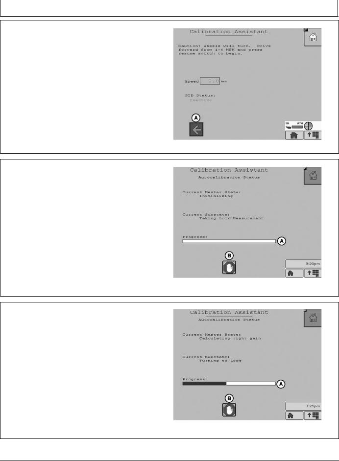
To start the Valve autocalibration process the machine must be moving forward at 1 to 4 mph. When the machine is moving at 1 to 4 mph press the resume switch to start the autocalibration process.
Select previous (A) to navigate back to WAS Calibration.
A—Previous
The autocalibration screen will display when the resume button is pressed. The progress bar (A) will start to fill during the autocalibration process.
To stop autocalibration select Stop (B) at any time. The operator can also turn the steering wheel at anytime to stop autocalibration. If the autocalibration is stopped at any time it must be completed before AutoTrac will operate.
NOTE: Do not turn the steering wheel during the autocalibration process unless it is an emergency. Turning the steering wheel will cause the test to stop. If the test is stopped it must be completed before AutoTrac will operate.
A—Progress Bar |
B—Stop |
PC13400 —UN—20APR11
BA31779,0000223 -19-04AUG11-17/21
PC13401 —UN—28JUL11
Autocalibration Status
BA31779,0000223 -19-04AUG11-18/21
Autocalibration process will go through several steps. The last step is calculating right min. The Progress bar will fill completely indicating the autocalibration is finished.
A—Progress Bar
|
PC13402 —UN—28JUL11 |
|
Calculating right min |
Continued on next page |
BA31779,0000223 -19-04AUG11-19/21 |
25-7 |
PN=20 |
|
090811 |
AutoTrac Controller—Raven
During the valve calibration if the Stop button is pressed or the steering wheel is moved the user is given the option to continue (A) the calibration or cancel (B).
A—Continue |
B—Cancel |
|
|
|
PC13964 —UN—03AUG11 |
|
|
BA31779,0000223 -19-04AUG11-20/21 |
|
|
|
|
|
|
When autocalibration is complete the main screen will |
|
|
appear. If the calibration completed successfully then |
|
|
system state (A) will read “READY”. If the calibration |
|
|
failed system state (A) will read “FAULT”. If calibration |
|
|
failed select CAL (B) to start the calibration process over. |
|
|
If the calibration process was aborted or not completed |
|
|
the system state (A) will read “Calibration Started”. |
|
|
If the calibration is successful then the Tool Box (C) will |
—UN—20APR11 |
|
appear on the screen. Tool Box gives access to vehicle |
||
health test. |
|
|
NOTE: Vehicle health test should only be completed |
|
|
by a dealer. |
|
PC13403 |
Selecting system information (D) will display information |
||
about the AutoTrac system. |
|
System State |
|
|
|
A—System State Ready |
C—Tool Box |
|
B—CAL |
D—Information |
|
|
|
BA31779,0000223 -19-04AUG11-21/21 |
|
|
|
|
|
|
Failed Calibrations |
|
• Not enough area to complete calibration without |
If calibration failure persists, check the Message Center |
stopping during the calibration step |
|
• Grabbing the steering wheel to avoid obstacles |
||
and/or contact your John Deere dealer. |
• Wheel angle sensor not responding |
|
A failed calibration may be the result of: |
• Valve not responding. |
|
• Incorrect inputs provided by the operator |
• Machine hardware failure |
|
|
||
CF86321,0000337 -19-23MAY11-1/1
25-8 |
PN=21 |
|
090811 |
AutoTrac Controller—Raven
Necessary Conditions for Activating
AutoTrac
|
|
|
|
Off-Track |
|||
40% |
Lateral Error |
||||||
Track No. 0 |
|
|
|
|
|
||
|
|
|
|
|
|||
|
|
|
|
|
|
||
|
|
|
|
|
|
|
|
|
40% |
|
|
|
|||
|
|
|
|||||
|
|
|
|
|
|
|
|
|
|
|
|
|
|
|
|
Track |
Track No. changes at 50% |
||||||
Spacing |
|||||||
|
|
|
|||||
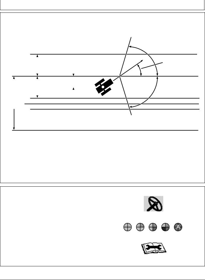
Track No. 1-S
Once tractor is at end of row operator must turn system to next pass. By turning steering wheel, AutoTrac is deactivated. Operator must turn onto next track.
AutoTrac can be activated by pressing resume switch only after following conditions are met:
NOTE: Calibration procedure must be complete with a passing status prior to using AutoTrac.
Once two pieces of the PIE are achieved, the operator can enable AutoTrac by selecting the Steer On icon.
If two pieces of the PIE can not be achieved, the operator will not be able to activate AutoTrac.
•A diagnostic button is located next to the PIE icon.
•If two pieces of the PIE can not be achieved, select wrench icon to view AutoTrac Diagnostics.
The Diagnostics page will indicate what is needed for each of the four PIE pieces and the status of all requirements.
80˚
Track Heading
Error
80˚
PC7051 —19—04FEB02
1.System is enabled (steering ON on RUN screen).
2.The machine is within 40% of track spacing.
3.Track heading is within 80° of track.
CF86321,0000338 -19-23MAY11-1/2
PC11972 —UN—09APR09
Steer On icon
PC11971 —UN—09APR09
Pie Pieces
PC11973 —UN—09APR09
AutoTrac may not become available until hydraulic |
|
temperature has reached pre set level (1 PIE piece only |
|
until warm). This issue will not provide any diagnostic |
|
code or show in the status menu. |
AutoTrac Diagnostics Wrench |
|
CF86321,0000338 -19-23MAY11-2/2 |
25-9 |
PN=22 |
|
090811 |
Loading...