


SeedStar™2 and SeedStar™XP Planter
Quick Reference Guide
|
|
|
|
|
|
|
|
|
|
|
|
|
A93891_19_17MAY12.indd 1 |
|
|
5/17/2012 8:19:41 AM |
|
|
|
|
|
||
|
|
|
|
||
|
|
|
|
||
|
|
|
|
|
|
|
|
|
|
|
|
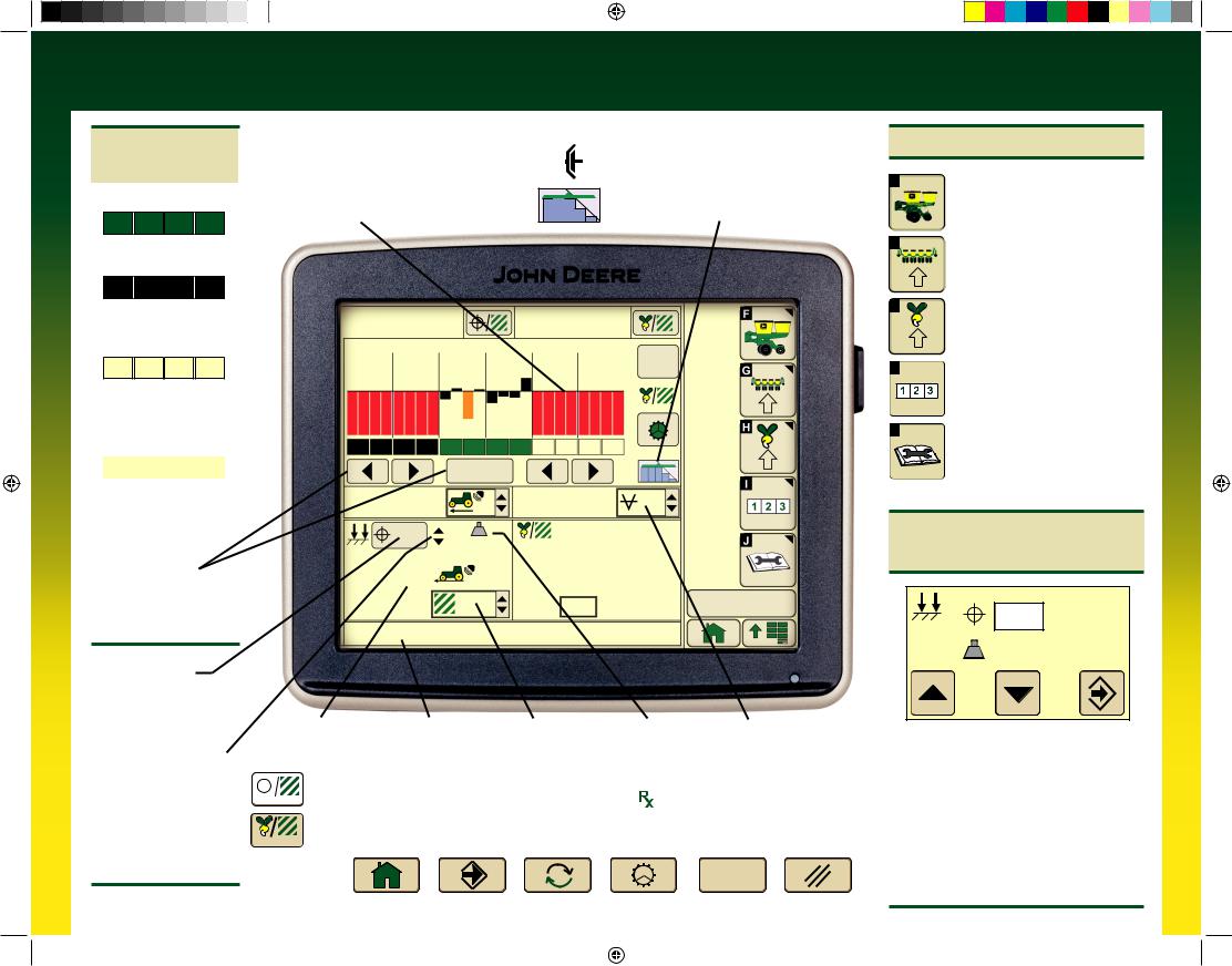
SeedStarTM2 Planter Quick Reference Guide
With Optional
RowCommandTM
Drive Status Bars
Green Bars: Section active and ready to plant.
Planter At a Glance
Black bars indicate row is planting normally.
Orange bars indicate row is planting above or below alarm setpoints.
Red bars indicate row is not planting.
Drives Status ICON
Clutch Icon: Sections can only be controlled manually by operator.
Section Icon: Sections are controlled by
John Deere Section ControlTM (when activated).
Black Bars: Section deactivated manually by operator.
Outlined Bars:
Section deactivated by SwathControlTM command (when activated).
Bars Not Visible:
Section active, but cannot be controlled manually or with RowCommandTM.
RowCommandTM
Buttons: Select buttons to turn sections on and off manually.
Target Pneumatic
Down Force Level
Select button to view Pneumatic Down Force Control Panel
Pneumatic Down Force System Indicator Arrows
Up arrow indicates system is increasing down force level.
Down arrow indicates system is decreasing down force level
32000 |
|
|
32300 |
32100 |
|
|
|
|
|
4 |
8 |
12 |
16 |
20 |
QS
Reset
Enable All
Sections
5.4 |
|
13.6 |
13.1 |
|
|
(mph) |
|
|
|
||
|
|
|
(In H2O) |
|
|
30 |
33 (lbs) |
|
Row |
(seeds/ac) |
|
|
|
|
|
||
|
Min: |
11 |
27300 |
|
|
|
|
|
|||
5.5 |
|
Max: |
16 |
32900 |
|
(mph) |
|
Scan: |
12 |
32200 |
|
40.0 |
|
2:43 pm |
|||
2 |
|
4 |
0 |
||
(ac) |
|
||||
HI warn row #16 |
|
|
|
|
|
|
|
|
|
Speed Display |
|
|
Caution Message |
User Defined |
Actual Pneumatic |
Vacuum |
|
||||||
|
|
|
|
|
|
|
|
|
|
|
Display |
|
Totals |
Down Force Level |
Level Icon |
|
|
Population and Rates |
|
|
|
|
|
|
|||||||||||
|
|
|
|
|
|
Target Seeds per Area displays the desired seeding rate entered in Planter Rates Setup. On VRD machines, |
|||||||||||
|
|
|
|
|
|
||||||||||||
|
|
|
(seeds/ac) |
|
select this button to toggle between programmed rates including |
prescriptions (Rate 6, VRD only). |
|||||||||||
|
|
||||||||||||||||
|
|
|
|
|
|
Average Seeds per Area displays the actual average rate planted. Select button to toggle between whole |
|||||||||||
|
(seeds/ac) |
planter average and drive section average. |
|
|
|
|
|||||||||||
Other Useful |
|
|
|
|
|
|
|
|
|
QS |
|
||||||
|
|
|
|
|
|
|
|
|
|
|
|
|
|
|
|
|
|
Buttons |
|
|
|
|
|
|
|
|
|
|
Reset |
|
|||||
|
Toggle Home |
Enter, Done, |
Toggle |
Rotate Seed |
Quick Start |
Cancel |
|||||||||||
|
|
|
|
|
|
|
|||||||||||
|
|
|
|
|
|
|
Screens |
Save, Finish |
|
Meters |
Reset |
|
|||||
Getting Started
F
Planter – Main: Select for planter main run screen.
GPlanter – Configuration:
Select to change planter frame, drives, and sensor configuration.
H |
Planter – Rates: Select to |
|
|
|
change crop type, rates, and |
|
meter configuration. |
I |
Totals: Select to view planted |
|
|
|
area, hours, and calculators. |
J |
Diagnostics: Select to view |
|
|
|
sensor readings and fault codes. |
Pneumatic Down Force
Control Panel
147 |
(lbs) |
145 |
(lbs) |
•Enter target down force in input box.
•Select up or down arrow buttons to change pneumatic down force by preset Step Value.
•Enter low down force level alarm set point and Step value in PDF Air Pressure Setup Screen.
•Select: Menu>>Planter>>Configuration Softkey>>Sensor Tab>>Select PDF Air Pressure from drop down menu.
A93891_19_17MAY12.indd 2 |
|
|
5/17/2012 8:19:43 AM |
|
|
||
|
|
|
|
Crop Setup – Ground Drive
Select Rates Softkey (H).
Select Crop Name from drop down menu. Select desired crop from list. If desired crop name is not listed, select a Custom crop name.
Select Target Rate input box and enter desire population.
High and low warning limits are automatically set to a percentage above and below target rate. To change limits, select High and Low Warning input boxes and enter a new value.
Refer to Rate Charts & Settings Manual or Seed Transmission Sprocket Calculator (Menu>>Planter>>Totals>>Calculator>>Seed Transmission).
To access Seed Estimators and Vacuum Calculator select Totals softkey (I) >> Calc tab >> and choose the desired calculator from the drop down menu.
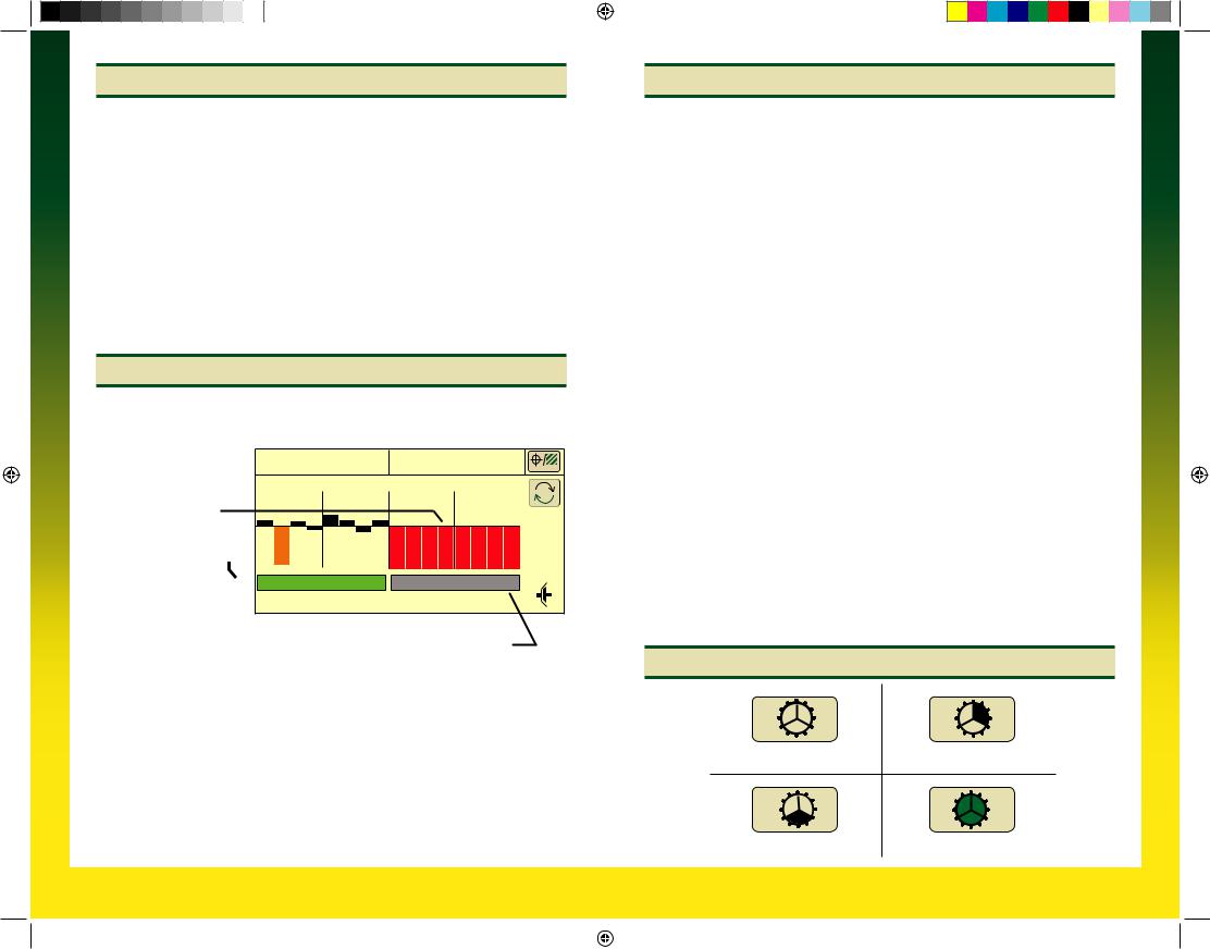
Standard Run Screen
Planter At a Glance
Black bars indicate row is planting normally.
Orange bars indicate row is planting above
or below alarm setpoints.
Red bars indicate row is not planting.
Drives Status Bar 
Green bar indicates that clutch or motor is engaged and drives are active.
32000 |
|
32000 |
(seeds/ac) |
4 |
8 |
12 |
|
Gray bar indicates that clutch or motor is disengaged and drives are inactive.
Transport Mode: 
To disable seed sensor warnings while in transport, navigate to: Planter >> Planter Configuration >> depress “Transport Mode” key. To disable “Transport Mode” to resume planting, depress key on screen.
Headland Warning Suppression:
Check box (Planter Configuration >> Sensor >> Seed) to disable seed sensor warnings when the planter is raised in field position (requires a height sensor and height sensor must be calibrated).
Crop Setup – Variable Rate Drive
Select Rates Softkey (H).
Select Use 1 Rate for All Motors check box. A check indicates one rate for all motors. An empty box indicates different rates for each motor.
Rate 6 is used for map based prescription. To enable controller to use a prescription, select the On drop down box under rate 6. From RUN screen select the Rx rate. Once rate is selected, the run page has a small Rx indicator near the Target Seeds per Area icon.
Select Crop Name from drop down menu. Select desired crop from list. If desired crop name is not listed, select a Custom crop name.
Select Disk Type drop down menu. If planter has mechanical meters, mechanical meter selections appear. If planter has vacuum meters, vacuum disk selections appear.
Select meter or crop from list.
Select Seed Disk drop down menu and select the vacuum disk used. Verify this disk is in meter.
Select Show Rates button, then select Change Rates button.
If using different rates for each motor, select Motor drop down menu to assign rates to each motor.
Select Rate drop down menu and choose a rate from the list to assign a population to that rate.
Select Target input box and enter the target population for the selected rate.
High and low warning limits are automatically set to a percentage above and below target rate. To change limits, select High and Low Warning input boxes and enter a new value.
To see a rate on the RUN page as a choice, select On and Off drop down box and choose ON.
Select Enter button.
VRD Status
1. |
2. |
No Activity |
Wheel Motion, Sensor Active |
3. |
4. |
Planter Lowered |
Drives Engaged |
A93891_19_17MAY12.indd 3 |
|
|
5/17/2012 8:19:44 AM |
|
|
||
|
|
|
|
 Loading...