


ST0726
ST0726
Snow Thrower
MTF-031071L
OPERATOR’S
MANUAL

INTRODUCTION
2
MTF-031071L
Congratulations on your purchase of a Frontier Snowthrower. It has been designed, engineered and manufactured to give you
the best possible dependability and performance. However, like all mechanical products, your machine will occasionally re-
quire adjustment and maintenance. This handbook should be read before operating or performing and adjustments on your
machine.
The instructions in this Owner’s Manual are written for a person with some mechanical ability. Like most service books, not
all the steps are described. Steps on how to loosen or tighten fasteners are steps anyone can follow with some mechanical
ability. Read and follow these instructions before you use the unit.
Know your product:: If you understand the unit and how the unit operates, you will get the best performance. As you read
this manual, compare the illustrations to the unit. Learn the location and the function of the controls. To help prevent an acci-
dent, follow the operating instructions and the safety rules. Keep this manual for future reference.
IMPORTANT: Many units are not assembled and are sold in cartons. It is the responsibility of the owner to make sure the as-
sembly instructions in this manual are exactly followed. Other units are purchased in an assembled condition. On assembled
units, it is the responsibility of the owner to make sure the unit is correctly assembled. The owner must carefully check the unit
according to the instructions in this manual before it is first used.
The warranty, found in this manual, details the coverage and limitations of this product. Registration of the warranty is
necessary and must be preformed by the dealer within sixty (60) days from the date of retail sale or delivery. The
Warranty Registration Form is located on the Frontier website.
RESPONSIBILITY OF THE OWNER
The responsibility of the owners to follow the instructions below.
1. Carefully read and follow the rules for safe operation.
2. Follow all the assembly instructions.
3. Inspect the unit.
4. Make sure that the operator of the unit knows how to correctly use all standard and accessory equipment.
5. Operate the unit only with guards, shields, and other safety items in place and working correctly.
6. Correctly adjust the unit.
7. Service the unit only with authorized or approved replacement parts.
8. Complete all maintenance on the unit.
Read And Keep This Book For
Future Reference. This Book Contains Important Information On:
SAFETY, ASSEMBLY, OPERATION AND MAINTENANCE.
PRODUCT INFORMATION
The owner must be certain that all the product information is included with this unit.
This information includes the INSTRUCTION BOOKS, the REPLACEMENT PARTS
and the WARRANTIES. This information must be included to make
sure state laws and other laws are followed.
RULES FOR SAFE OPERATION
3
MTF-031071L
IMPORTANT
WARNING: Always disconnect the spark plug wire and place it where it cannot make contact with
spark plug to prevent accidental starting during: Preparation, Maintenance, or Storage of your
snowthrower.
Safe Operation Practices for Snowthrowers
As Recommended By: American National Standards Institute.
Engine Exhaust, some of its constituents, and
certain vehicle components contain or emit
chemicals known to the State of California to
cause cancer and birth defects or other repro-
ductive harm.
Battery posts, terminals and related accesso-
ries contain lead and lead compounds, chemi-
cals known to the State of California to cause
cancer and birth defects or other reproductive
harm. WASH HANDS AFTER HANDLING.
IMPORTANT: Safety standards require operator presence
controls to minimize the risk of injury. Your snowthrower is
equipped with such controls. Do not attempt to defeat the
function of the operator presence control under any cir-
cumstances.
Training
1. Read the operating and service instruction manual care-
fully. Be thoroughly familiar with the controls and the
proper use of the equipment. Know how to stop the unit
and disengage the controls quickly.
2. Never allow children to operate the equipment. Never
allow adults to operate the equipment without proper
instruction.
3. Keep the area of operation clear of all persons, particu-
larly small children and pets.
4. Exercise caution to avoid slipping or falling especially
when operating in reverse.
Preparation
1. Thoroughly inspect the area where the equipment is to
be used and remove all doormats, sleds, boards, wires,
and other foreign objects.
2. Disengage all clutches before starting the engine
(motor).
3. Do not operate the equipment without wearing adequate
winter outer garments. Wear footwear that will improve
footing on slippery surfaces.
4. Handle fuel with care; it is highly flammable.
a. Use an approved fuel container.
b. Never remove fuel tank cap or add fuel to a running en-
gine (motor) or hot engine (motor).
c. Fill fuel tank outdoors with extreme care. Never fill fuel
tank indoors.
d. Replace fuel cap securely and wipe up spilled fuel.
e. Never store fuel or snowthrower with fuel in the tank
inside of a building where fumes may reach an open
flame or spark.
f. Check fuel supply before each use, allowing space for
expansion as the heat of the engine (motor) and/or sun
can cause fuel to expand.
5. For all units with electric starting motors use electric
starting extension cords certified CSA/UL. Use only with
a receptacle that has been installed in accordance with
local inspection authorities.
6. Adjust the snowthrower height to clear gravel or crushed
rock surface.
7. Never attempt to make any adjustments while the en-
gine (motor) is running (except when specifically recom-
mended by manufacturer).
8. Let engine (motor) and snowthrower adjust to outdoor
temperatures before starting to clear snow.
9. Always wear safety glasses or eye shields during oper-
ation or while performing an adjustment or repair to pro-
tect eyes from foreign objects that may be thrown from
the snowthrower.
Operation
1. Do not operate this machine if you are taking drugs or
other medication which can cause drowsiness or affect
your ability to operate this machine.
2. Do not use this machine if you are mentally or physically
unable to operate this machine safely.
3. Do not put hands or feet near or under rotating parts.
Keep clear of the discharge opening at all times.
4. Exercise extreme caution when operating on or crossing
gravel drives, walks or roads. Stay alert for hidden haz-
ards or traffic.
5. After striking a foreign object, stop the engine (motor),
remove the wire from the spark plug, thoroughly inspect
snowthrower for any damage, and repair the damage
before restarting and operating the snowthrower.
6. If the unit should start to vibrate abnormally, stop the
engine (motor) and check immediately for the cause.
Vibration is generally a warning of trouble.
RULES FOR SAFE OPERATION
4
MTF-031071L
7. Stop the engine (motor) whenever you leave the operat-
ing position, before unclogging the auger/impeller hous-
ing or discharge chute and when making any repairs,
adjustments, or inspections.
8. When cleaning, repairing, or inspecting, make certain
the auger/impeller and all moving parts have stopped
and all controls are disengaged. Disconnect the spark
plug wire and keep the wire away from the spark plug to
prevent accidental starting.
9. Take all possible precautions when leaving the snow-
thrower unattended. Disengage the auger/ impeller, stop
engine (motor), and remove key.
10.Do not run the engine (motor) indoors, except when
starting the engine (motor) and for transporting the
snowthrower in or out of the building. Open the outside
doors; exhaust fumes are dangerous (containing CAR-
BON MONOXIDE, an ODORLESS and DEADLY GAS).
11.Do not clear snow across the face of slopes. Exercise
extreme caution when changing direction on slopes. Do
not attempt to clear steep slopes.
12.Never operate the snowthrower without proper guards,
plates or other safety protective devices in place.
13.Never operate the snowthrower near enclosures, auto-
mobiles, window wells, drop- offs, and the like without
proper adjustment of the snow discharge angle. Keep
children and pets away.
14.Do not overload the machine capacity by attempting to
clear snow at too fast a rate.
15.Never operate the machine at high transport speeds on
slippery surfaces. Look behind and use care when back-
ing up.
16.Never direct discharge at bystanders or allow anyone in
front of the unit.
17.Disengage power to the collector/impeller when snow-
thrower is transported or not in use.
18.Use only attachments and accessories approved by the
manufacturer of the snowthrower (such as tire chains,
electric start kits, ect.).
19.Never operate the snowthrower without good visibility or
light. Always be sure of your footing and keep a firm
hold on the handles. Walk;never run.
20.Do not over- reach. Keep proper footing and balance at
all times.
21.Exercise caution if operating on steep sloping surfaces.
22.This snowthrower is for use on sidewalks, driveways
and other ground level surfaces.
23.Do not use the snowthrower on surfaces above ground
level such as roofs of residences, garages, porches or
other such structures or buildings.
Maintenance And Storage
1. Check shear bolts and other bolts at frequent intervals
for proper tightness to be sure the equipment is in safe
working condition.
2. Never store the snowthrower with fuel in the tank inside
a building where ignition sources are present such as
hot water and space heaters, clothes dryers, and the
like. Allow the engine (motor) to cool before storing in
any enclosure.
3. Always refer to operator’s guide instructions for import-
ant details if the snowthrower is to be stored for an ex-
tended period.
4. Maintain or replace safety and instruction labels, as
necessary .
5. Run the snowthrower a few minutes after throwing
snow to prevent freeze- up of the auger/impeller.
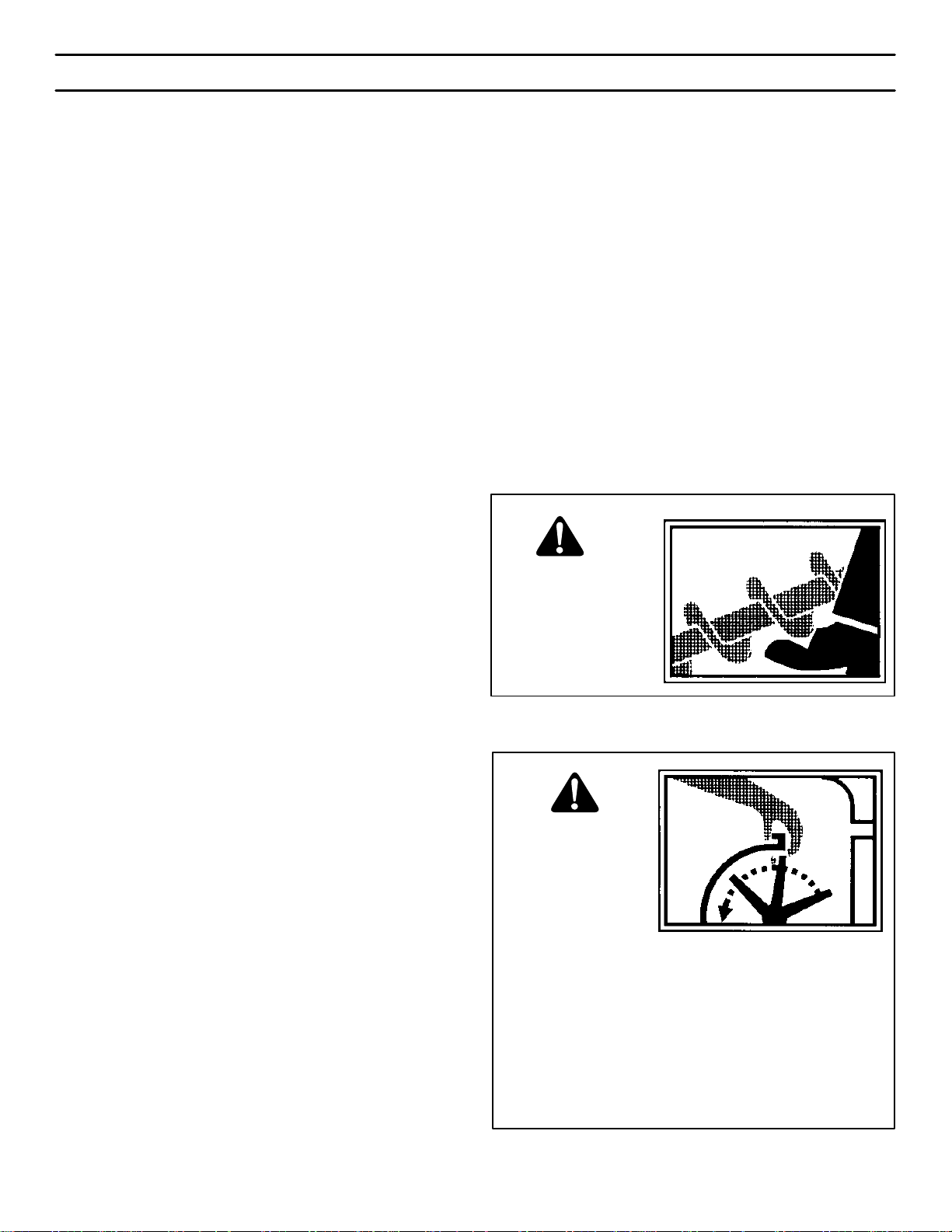
WARNING: Avoid
injury from rotating
auger- keep hands,
feet, and clothing
away.
• Stop engine/motor before removing debris.
• Do not walk in front of running machine.
• Do not discharge at bystanders.
• Keep people and pets a safe distance from the
machine.
• Before leaving machine, shut off engine/ motor
and remove key.
WARNING: Do not
use hands to un-
clog discharge
chute.

TABLE OF CONTENTS
5
MTF-031071L
SAFETY DECALS 6. . . . . . . . . . . . . . . . . . . . . . . . . . . . . . . . . . . . . . . . . . . . . . .
WARRANTY 7. . . . . . . . . . . . . . . . . . . . . . . . . . . . . . . . . . . . . . . . . . . . . . . . . . . .
OWNER’S INFORMATION 7. . . . . . . . . . . . . . . . . . . . . . . . . . . . . . . . . . . . . . .
ASSEMBLY 8. . . . . . . . . . . . . . . . . . . . . . . . . . . . . . . . . . . . . . . . . . . . . . . . . . . .
TOOLS REQUIRED FOR ASSEMBLY 8. . . . . . . . . . . . . . . . . . . . . . . . . . .
CONTENTS OF SHIPPING CARTON 8. . . . . . . . . . . . . . . . . . . . . . . . . . . .
PARTS BAGS CONTENTS 8. . . . . . . . . . . . . . . . . . . . . . . . . . . . . . . . . . . . .
UNPACKING 9. . . . . . . . . . . . . . . . . . . . . . . . . . . . . . . . . . . . . . . . . . . . . . . . .
UPPER HANDLE AND CRANK ASSEMBLY 10. . . . . . . . . . . . . . . . . . . . . .
CHECK THE CABLES 10. . . . . . . . . . . . . . . . . . . . . . . . . . . . . . . . . . . . . . . . .
HOW TO SET THE LENGTH OF THE CABLES 10. . . . . . . . . . . . . . . . . . .
SNOW CHUTE ASSEMBLY 11. . . . . . . . . . . . . . . . . . . . . . . . . . . . . . . . . . . .
SHIFTER LEVER KNOB ASSEMBLY 11. . . . . . . . . . . . . . . . . . . . . . . . . . . .
IMPORTANT! BEFORE YOU START OPERATING 11. . . . . . . . . . . . . . . .
OPERATION 12. . . . . . . . . . . . . . . . . . . . . . . . . . . . . . . . . . . . . . . . . . . . . . . . . . . .
ENGINE AND SNOWTHROWER CONTROLS 12. . . . . . . . . . . . . . . . . . . .
SNOWTHROWER OPERATION 13. . . . . . . . . . . . . . . . . . . . . . . . . . . . . . . .
WHEEL LOCK OUT PIN 14. . . . . . . . . . . . . . . . . . . . . . . . . . . . . . . . . . . . . . .
HOW TO REMOVE SNOW FROM AUGER 15. . . . . . . . . . . . . . . . . . . . . . .
HOW TO SET THE DRIFT CUTTERS 15. . . . . . . . . . . . . . . . . . . . . . . . . . .
BEFORE STARTING ENGINE 16. . . . . . . . . . . . . . . . . . . . . . . . . . . . . . . . . .
TO START ENGINE 17. . . . . . . . . . . . . . . . . . . . . . . . . . . . . . . . . . . . . . . . . . .
OPERATING TIPS 18. . . . . . . . . . . . . . . . . . . . . . . . . . . . . . . . . . . . . . . . . . . .
SERVICE RECOMMENDATIONS 19. . . . . . . . . . . . . . . . . . . . . . . . . . . . . . . . .
MAINTENANCE 20. . . . . . . . . . . . . . . . . . . . . . . . . . . . . . . . . . . . . . . . . . . . . . . . .
LUBRICATION 20. . . . . . . . . . . . . . . . . . . . . . . . . . . . . . . . . . . . . . . . . . . . . . . .
ENGINE 22. . . . . . . . . . . . . . . . . . . . . . . . . . . . . . . . . . . . . . . . . . . . . . . . . . . . .
AUGER HOUSING HEIGHT ADJUSTMENT 23. . . . . . . . . . . . . . . . . . . . . .
BELT ADJUSTMENT 24. . . . . . . . . . . . . . . . . . . . . . . . . . . . . . . . . . . . . . . . . .
HOW TO REPLACE THE BELTS 25. . . . . . . . . . . . . . . . . . . . . . . . . . . . . . . .
BELT GUIDE ADJUSTMENT 27. . . . . . . . . . . . . . . . . . . . . . . . . . . . . . . . . . .
TRACTION DRIVE CABLE ADJUSTMENT 28. . . . . . . . . . . . . . . . . . . . . . .
HOW TO ADJUST OR REPLACE THE FRICTION WHEEL 29. . . . . . . . .
HOW TO REMOVE THE SNOW HOOD 32. . . . . . . . . . . . . . . . . . . . . . . . . .
AUGER SHEAR BOLT REPLACEMENT 33. . . . . . . . . . . . . . . . . . . . . . . . .
TO ADJUST OR REPLACE THE SPARK PLUG 33. . . . . . . . . . . . . . . . . . .
STORAGE 34. . . . . . . . . . . . . . . . . . . . . . . . . . . . . . . . . . . . . . . . . . . . . . . . . . . . . .
TROUBLE SHOOTING CHART 35. . . . . . . . . . . . . . . . . . . . . . . . . . . . . . . . . . .
REPLACEMENT PARTS 36. . . . . . . . . . . . . . . . . . . . . . . . . . . . . . . . . . . . . . . . .
PARTS SCHEMATICS 37. . . . . . . . . . . . . . . . . . . . . . . . . . . . . . . . . . . . . . . . . . .
SPECIFICATIONS 56. . . . . . . . . . . . . . . . . . . . . . . . . . . . . . . . . . . . . . . . . . . . . . .
SAFETY DECALS
6
MTF-031071L
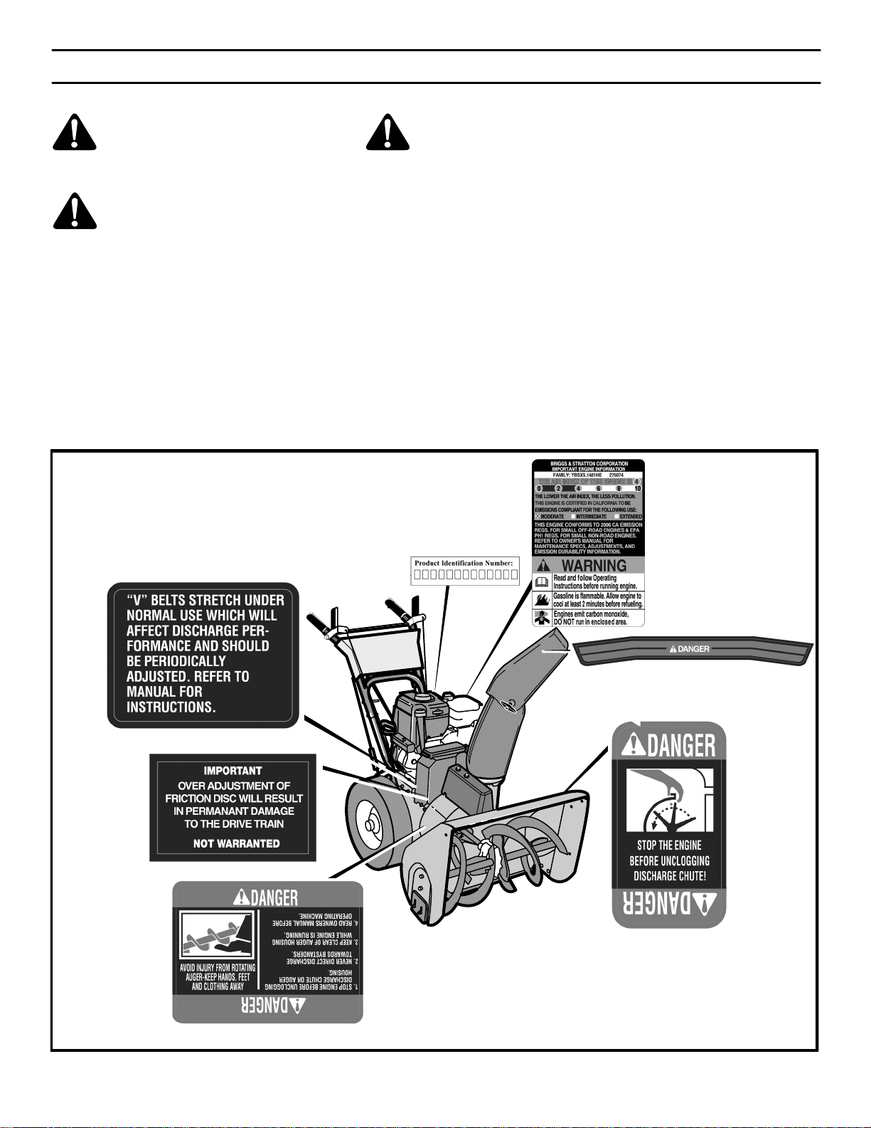
WARNING: If safety decals are dam-
aged or missing, replace immediately.
Look for this symbol to indicate important safe-
ty precautions. This symbol indicates: “Atten-
tion! Become Alert! Your Safety Is At Risk.”
Before operation of your snowthrower, read the safety de-
cals as shown on your snowthrower. The cautions and
warnings are for your safety. To avoid a personal injury or
damage to your snowthrower, understand and follow all
safety decals. If you have any questions regarding the
meaning or how to comply with the instructions, do not op-
erate until you understand the purpose for the warning or
danger given in the safety decal. If you do not understand
the meaning, then thoroughly read all safety and operation
instructions in this Owner’s Manual or contact your local
dealer.
If any safety decals become worn or damaged and cannot
be read, order replacement decals from your local dealer.
Identifying Your Snowthrower
The snowthrower has two (2) identifying numbers: (1) unit
model number: (2) unit serial number. The two preceding
numbers are required to insure that the proper replace-
ment parts are obtained when required. If you have any
questions concerning parts, service, or technical data, con-
tact the dealer where the unit was purchased.
For complete warranty information refer to the warranty in
the Owner’s Information section of this manual.
Figure 1

OWNER’S INFORMATION
MTF-031071L
7
THREE YEAR LIMITED WARRANTY
Murray warrants to the original purchaser of this Frontier Branded Snowthrower that this unit shall be free from defects in
material and workmanship under normal use and service for a period of Three (3) Year from the date of purchase; however,
this warranty does not cover accessories (such as electric starters) and Normal Wear Parts (except as noted below) as the
companies that manufacture these items furnish their own warranties and provide service through their authorized field
service facilities. For additional information, see the warranties covering these particular parts. If you are uncertain whether
your unit contains or is equipped with one or more of these parts, consult your dealer prior to purchase. Subject to the terms
and conditions noted in this Limited Warranty, we shall, at our option, repair or replace at no cost to the original purchaser
any part covered by this Limited Warranty during the applicable warranty period.
Normal Wear Parts are defined as drive belts, augers, shear pins, tires and headlights. These parts are warranted to be free
from defects in material and workmanship as delivered with the product. Any claim for repair or replacement of Normal Wear
Parts must be made within thirty (30) days of the date of purchase. No claims involving damage caused from material use,
abuse or misuse will be honored.
This Murray Three (3) Year Limited Warranty for your Frontier Branded Snowthrower is your exclusive remedy; however,
this warranty is void or does not apply to any unit that has been tampered with, altered, misused, abused. If used for
commercial and/or professional (non-homeowner) uses, the duration of this warranty is ninety (90) days after the date of
purchase. Your warranty does not cover minor mechanical adjustments which are not due to any defect in material or
workmanship. For assistance in making such adjustments, consult your Operator’s Manual.
The engine on this Frontier Branded Snowthrower is warranted to the original purchaser for a Three (3) Year Limited
Warranty by the equipment manufacturer. See your engine manual for information regarding the warranty policy and items
covered under warranty. See your authorized John Deere/Frontier Dealer for service or replacement parts.
To make a claim under this Murray Three (3) Year Limited Warranty for your Frontier Branded Snowthrower, return the unit
(or if authorized in advance, the defective part) along with your proof of purchase to an Authorized John Deere/Frontier Dealer
near you. To locate the nearest Authorized John Deere/Frontier Dealer, check the Yellow Page listings in your local telephone
directory. If you return the entire unit, John Deere/Frontier will repair all warranty items. If authorize to return the defective
part only, John Deere/Frontier will either replace or repair the part. This Murray Three (3) Year Limited Warranty for your
Frontier Branded Snowthrower gives you specific legal rights, and you may also have other rights which vary from state to
state.
This Limited Warranty is given in lieu of all other expressed and implied warranties including the implied
warranty of merchantability and warranty of fitness for a particular purpose. If you need additional information on this
written warranty or assistance in obtaining service, contact you local John Deere/Frontier Dealer.
MB
DATE PURCHASED:
MODEL NO:
SERIAL NO:
STORE WHERE PURCHASED:
ADDRESS:
CITY: STATE:
TELEPHONE :
Record this information about your unit so that you will
be able to provide it in case of loss or theft.
FOR YOUR RECORDS
ASSEMBLY
8
MTF-031071L
TOOLS REQUIRED FOR ASSEMBLY
1 - Knife
2 - 1/2” wrenches (or adjustable wrenches)
2 - 9/16” wrenches (or adjustable wrenches)
2 - 3/4” wrenches (or adjustable wrenches)
1 - 3/8” wrenches (or adjustable wrenches)
1 - Pair pliers or screw driver (to spread cotter pin)
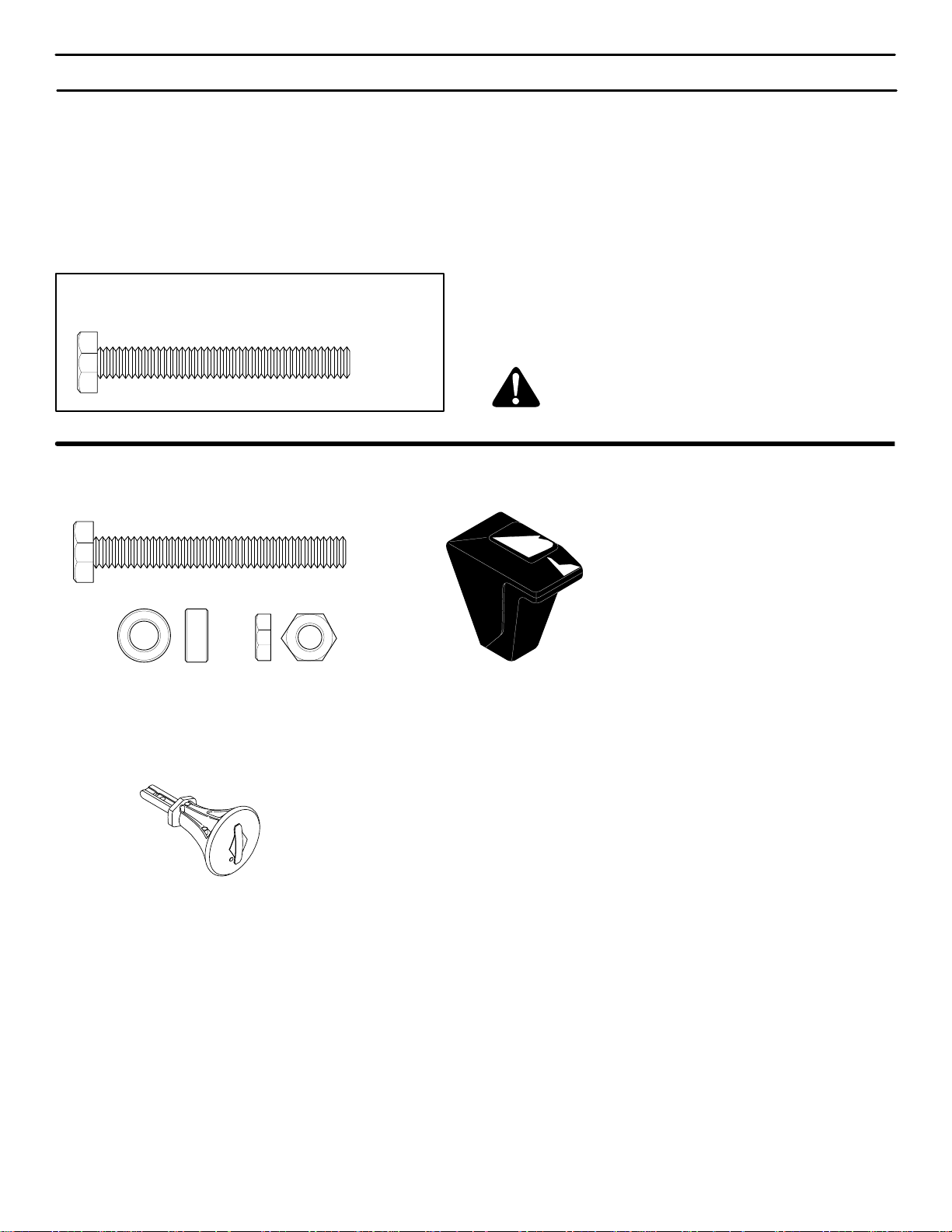
HOW TO MEASURE SCREW SIZE
LENGTH
DIAMETER
CONTENTS OF SHIPPING CARTON
1- Snowthrower
1- Container of Fuel Stabilizer (Located in Parts Bag)
1- Snow Chute Assembly
1- Crank Assembly
1- Parts Bag
WARNING: Always wear safety glasses or eye
shields while assembling snowthrower.
PARTS BAGS CONTENTS:
1 - Shift Lever Knob
(not actual size)
1 - Ignition Keys
*2- Shear Bolt
*2- Nut
* 2-Spacer
* Non Assembly parts are found in toolbox located on top of belt cover.
ASSEMBLY
9
MTF-031071L
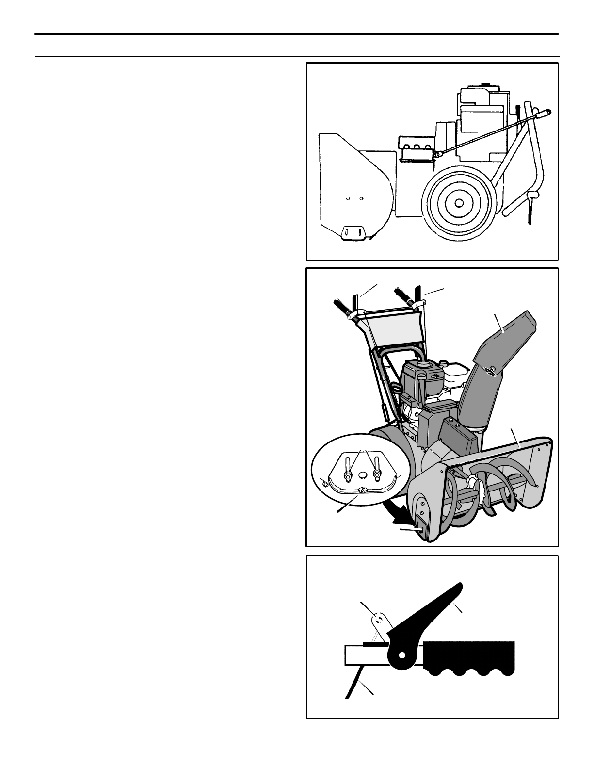
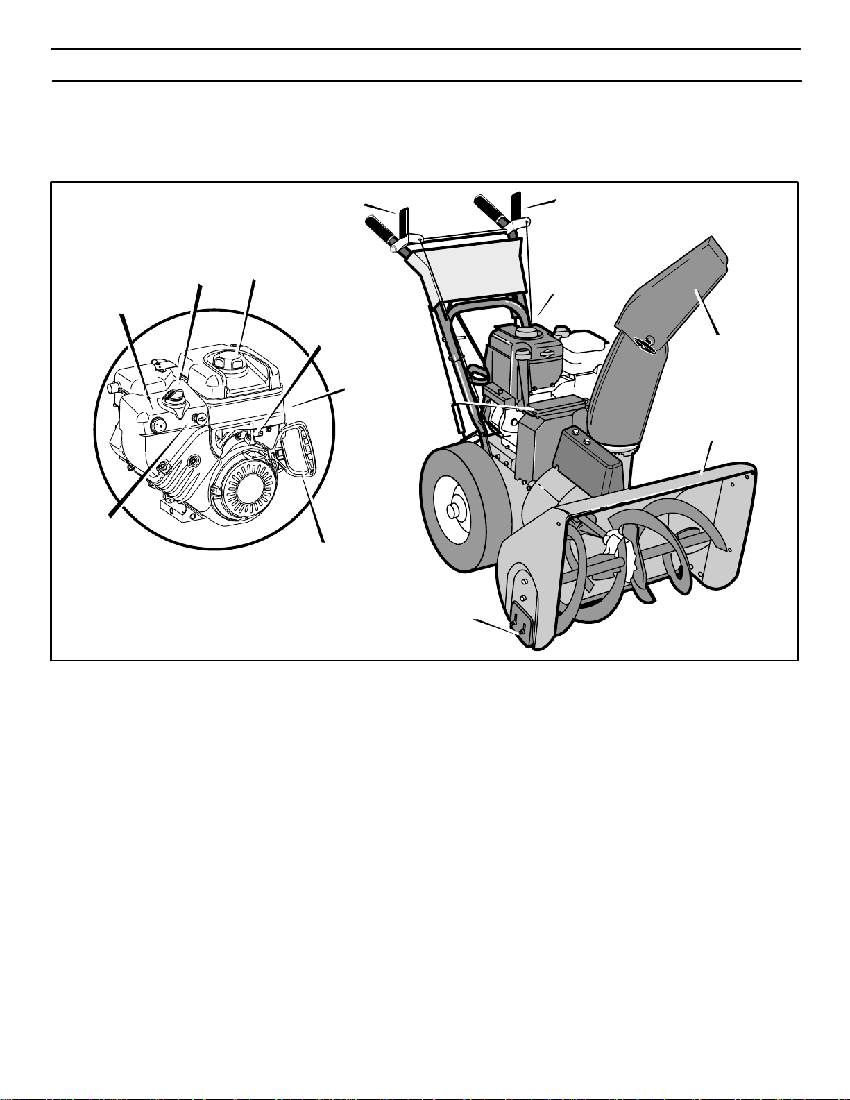
Figure 2 shows the snowthrower in the shipping position.
Figure 3 shows the snowthrower completely assembled.
Reference to right and left hand side of the snowthrower is
from the operator’s position at the handle.
UNPACKING
1. Locate the two tear tabs at the bottom of the carton.
2. Pull the tear tape no more than twelve inches (30.48cm.)
at a time. Re-grasp tape next to the carton and pull
again. Repeat until all the tape is torn off.
3. After the tape has been completely removed from the
carton, remove the carton from the base. Cut all four cor-
ners and fold the sides toward the center for easy dispos-
al.
4. Remove the plastic bag that covers the unit.
5. Locate and remove the parts bag.
NOTE: Set the fuel stabilizer aside until adding
gasoline to the fuel tank. We recommend that fuel
stabilizer is added to the fuel each time that gasoline
is added to the fuel tank.
6. For shipping purposes, the height adjust skids are at-
tached to the pallet. Remove the screw that secures
each height adjust skid to the pallet. (See Figure 2).
7. Roll the snowthrower off the carton by pulling on the low-
er handle.
CAUTION: DO NOT back over cables.
8. Remove the packing material from the handle assembly.
9. Cut ties securing the clutch control cables to the lower
handle.
Figure 2
Figure 3
Auger Drive Lever
Traction Drive Lever
Snow Chute Deflector
Height Adjust
Skid
Auger Housing
Screw
Figure 4
”Z” Fitting
Drive Lever
Cable
ASSEMBLY
10
MTF-031071L
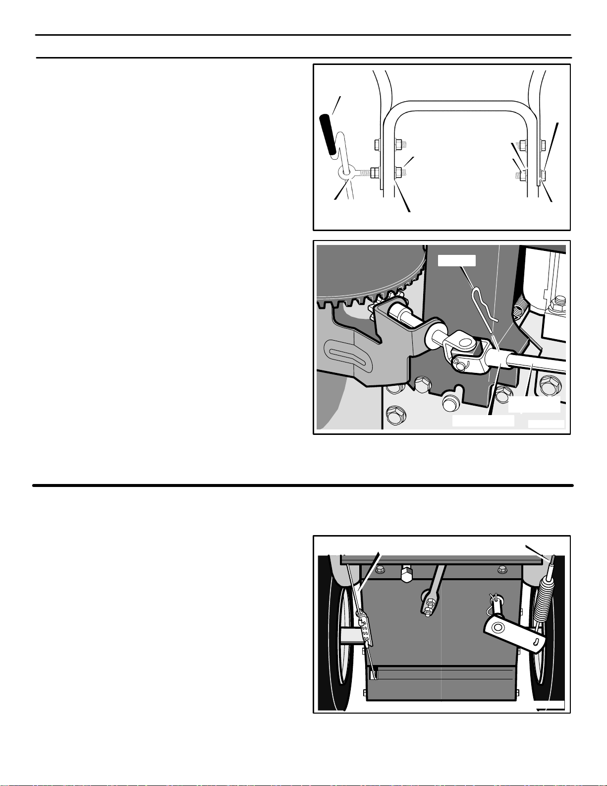
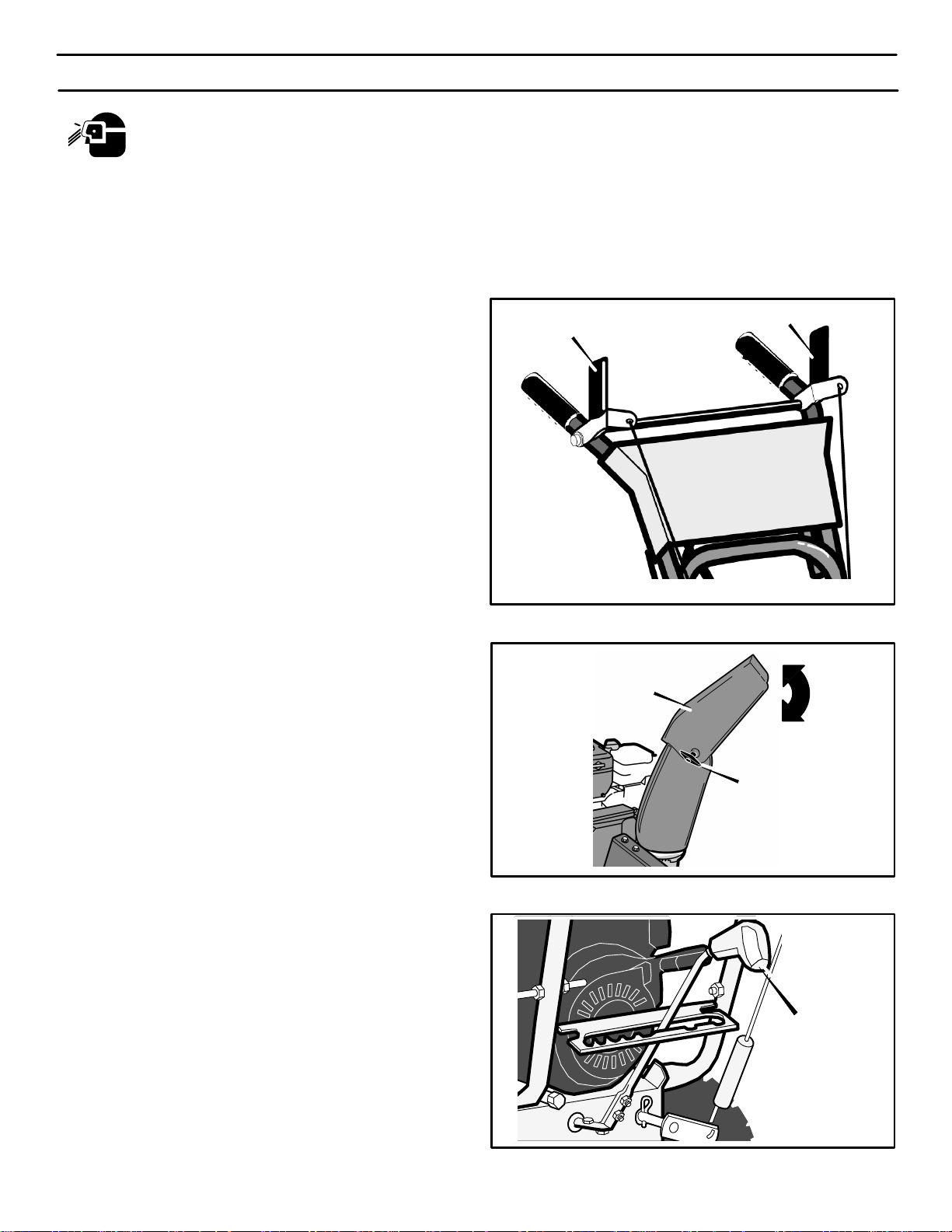
UPPER HANDLE AND CRANK ASSEMBLY
1. Loosen, but do not remove the screws, flatwashers, lock-
washers and hex nuts in the upper holes of the lower han-
dle.
2. Remove the fasteners and the crank assembly eyebolt
from the lower holes of the lower handle.
3. Raise upper handle into operating position. Upper han-
dle should be to the outside of the lower handle.
NOTE: Make sure the cables are not caught between
the upper and lower handle.
4. Install the fasteners and the crank assembly eyebolt that
were removed in step 2. DO NOT tighten until all fasten-
ers are in place.
5. Attach the crank rod to the universal joint assembly with
the hair pin (see Figure 6).
6. Tighten nut on eye bolt. Make sure eye bolt is properly
aligned and the crank can freely rotate.
7. Tighten all handle bolts.
NOTE: Make sure crank does not touch carburetor
cover.
Figure 5
Crank
Eye Bolt
Nut
Flatwasher
Bolt
Lockwasher
Flatwasher
Locknut
Figure 6
Crank Rod
Assembly
Universal Joint
Hair Pin
CHECK THE CABLES
1. If control cables have become unattached from motor
mount frame, reconnect cables as shown in Figure 7.
2. For cable adjustments, see “How To Check And Adjust
The Cables” in the MAINTENANCE section.
HOW TO SET
THE LENGTH OF THE CABLES
The cables were adjusted at the factory and no adjustments
should be necessary. However, after the handles are put in
the operating position, the cables can be too tight or too
loose. If a n a d j u s t m ent is necessary, see “How T o Check And
Adjust The Cables” in the MAINTENANCE section.
Figure 7
Traction Drive Cable
Auger Drive Cable
ASSEMBLY
11
MTF-031071L
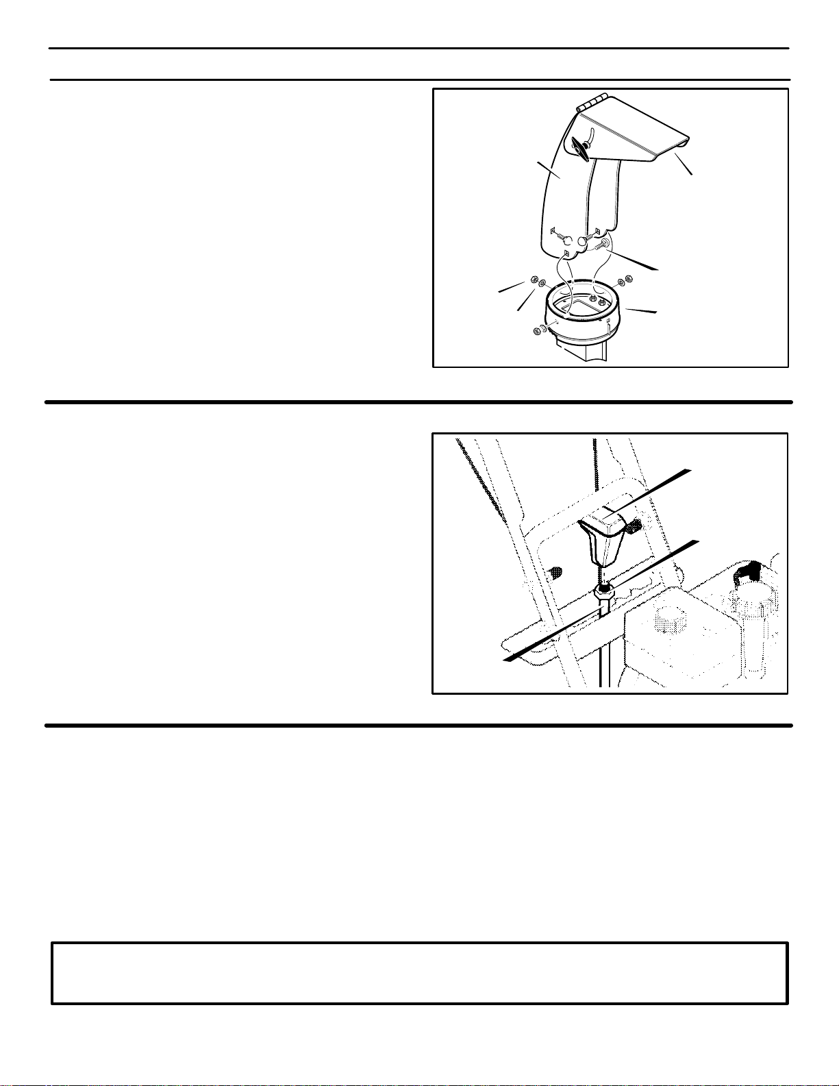
SNOW CHUTE ASSEMBLY
1. Position the snow chute onto the snow chute flange. Al-
ign the three holes in the snow chute with holes in snow
chute flange. (See Figure 8)
2. Place three 5/16-18 carriage bolts from inside of chute
as shown in Figure 8. (hardware is found in parts bag)
3. Place three 5/16-18 flatwashers and three 5/16-18 nuts
on outside of flange.
4. Tighten all carriage bolts securely.
NOTE: DO NOT overtigten carriage bolts.
Figure 8
Chute Extension
Snow Chute Deflector
Nut
Flatwasher
Flange
Carriage Bolts
SHIFTER LEVER KNOB ASSEMBLY
1. Thread the shifter knob onto the threaded end of the
shifter lever until it is snug against the hex nut and the lip
is pointed away from the engine (See Figure 9). On
some models, the shifter knob is attached.
2. Tighten hex nut against the bottom of the shifter lever
knob.
Figure 9
Shifter Lever
Hex Nut
Shifter
Knob
CHECK THE TIRES
The tires were over inflated for shipment. Check the tire
pressure in the tires. See the sidewall of the tire for the
proper inflation.
IMPORTANT! BEFORE YOU START
OPERATING
r Check the fasteners. Make sure all fasteners are
tight.
r On electric start models, the unit was shipped with
the starter cord plugged into the engine. Before
operating, unplug the starter cord from the engine.
NOTE: This snowthrower was shipped WITH OIL in the engine. See “Before Starting Engine”
instructions in the Operation section of this manual before starting engine.
OPERATION
12
MTF-031071L
READ THIS OWNER’S MANUAL AND SAFETY RULES BEFORE OPERATING YOUR SNOWTHROWER. Compare the
illustrations with your SNOWTHROWER to familiarize yourself with the location of various controls and adjustments. Save
this manual for future reference.
Figure 10
Auger Drive Clutch Lever
Traction Drive Clutch Lever
Snow Chute
Deflector
Auger Housing
Height
Adjust Skid
Toolbox
Primer Button
Gas Fill
Starter Handle
Throttle Control
Lever
Ignition Key
Choke Control
Electric
Start Button
Crank
ENGINE AND SNOWTHROWER CONTROLS
ENGINE CONTROLS
Throttle Control Lever - Controls the engine speed.
Choke Control- Use to start a cold engine.
Electric Start Button - Used to start the engine using the
120 volt electric starter.
Prime Button - Used to inject fuel directly into carburetor
manifold to insure fast starts in cool weather.
Ignition Key - Must be inserted to start engine. Pull out to
stop. Do not turn ignition key.
Starter Handle - Starts the engine manually.
SNOWTHROWER CONTROLS
Speed Select Lever - Allows the operator to use one of six
(6) forward and two (2) reverse speeds. T o shift, move speed
select lever to desired position.
NOTE: Do not move speed select lever while Traction
Drive Clutch is engaged. This may result in severe
damage to drive system.
Auger Drive Clutch Lever - Used to engage and disengage
the auger and impeller. To engage push down, to disengage
release.
Traction Drive Clutch Lever - Used to propel snowthrower
forward or reverse. Push down to engage, release to
disengage.
Snow Chute Deflector - Changes the direction the snow is
blown.
Crank - Used to change direction of the snow discharge.
Turn handle clockwise to turn chute to right. Turn handle
counter clockwise to turn chute to left.
Height Adjust Skid - Used to adjust ground clearance of
auger housing.
Toolbox - Spare shear pins, shear bolt wrenches and
spacers are located in toolbox.
OPERATION
13
MTF-031071L
The operation of any snowthrower can result in foreign objects being thrown into the eyes,which can
result in severe eye damage. Always wear safety glasses or eye shields before beginning snowthrower
Operation. We recommend standard safety glasses or Wide Vision Safety Mask for over spectacles.
SNOWTHROWER OPERATION
The most effective use of the snowthrower will be established
by experience, taking into consideration the terrain, wind
conditions and building location which will determine the
direction of the discharge chute.
NOTE: Do not blow snow toward a building as hidden
objects could be blown with sufficient force to cause
damage.
TO STOP YOUR SNOWTHROWER
1. To stop throwing snow, release the auger drive lever.
(see Figure 11).
2. To stop the wheels, release the traction drive lever.
3. To stop the engine, push the throttle control lever to of f
and pull out the ignition key.
TO CONTROL SNOW DISCHARGE
1. Rotate the crank to set the direction (left to right) of the
discharge chute (see Figure 10).
2. Adjust the snow chute deflector. Loosen the wing nut
on the side of the snow chute deflector. Raise the
snow chute deflector for more distance or lower for less
distance. Tighten wing nut. (see Figure 12).
HOW TO MOVE FORWARD AND BACKWARD
1. Start the engine. See “To Start Engine” in the Operation
section.
NOTE: Always release the traction drive lever before
moving the speed select lever.
2. Ground speed is determined by snow conditions. Set the
speed select lever (see Figure 13) in one of the follow-
ing positions.
1-2 Wet, Heavy, Slushy, Extra Deep
3 Moderate
4-5 Very Light
6 Transport Only
IMPORTANT: Before operating, make sure the area in
front of snowthrower is clear of bystanders or
obstacles.
3. Engage the traction drive lever (see Figure 11). As the
snowthrower starts to move, maintain a firm hold on the
handles and guide the snowthrower along the cutting
path. Do not attempt to push the snowthrower.
4. To stop forward motion, release the traction drive lever.
5. To move the snowthrower backwards, move the speed
select lever into either first or second reverse position
and engage the traction drive lever.
Auger Drive Lever
Traction Drive Lever
Figure 11
Figure 12
Wing Nuts
Chute Deflector
Figure 13
Speed Select Lever
OPERATION
14
MTF-031071L
TO THROW SNOW
1. Push down the auger driver lever (right hand). See
Figure 11.
2. To stop throwing snowl, release the auger drive lever.
NOTE: When clearing wet, heavy snow, it is
recommended that the ground speed of the unit be
reduced, maintain full throttle and do not attempt to
clear the full width of the unit.
For additional operating instructions see “Operating
Tips” in the Operation section.
WARNING: Read Owner’s Manual before oper-
ating machine. This machine can be dangerous
if used carelessly.
Never operate the snowthrower without all guards,
covers, and shields in place.
Never direct discharge towards windows or allow by-
standers near machine while engine is running.
Stop the engine whenever leaving the operating posi-
tion.
Disconnect spark plug before unclogging the impeller
housing or the discharge chute and before making re-
pairs or adjustments.
When leaving the machine, remove the ignition key.
To reduce the risk of fire, keep the machine clean and
free from spilled gas, oil and debris.
WARNING: Never run engine indoors or in an
enclosed, poor ventilated area. Engine exhaust
contains CARBON MONOXIDE, an OR-
DERLESS and DEADLY GAS.
Keep hands, feet, hair and loose clothing away from
any moving parts on engine and snowthrower.
Temperature of muffler and nearby areas can exceed
150_ F (66_ C). Avoid these areas.
DO NOT allow children or young teenagers to operate
or be near snowthrower while it is operating.
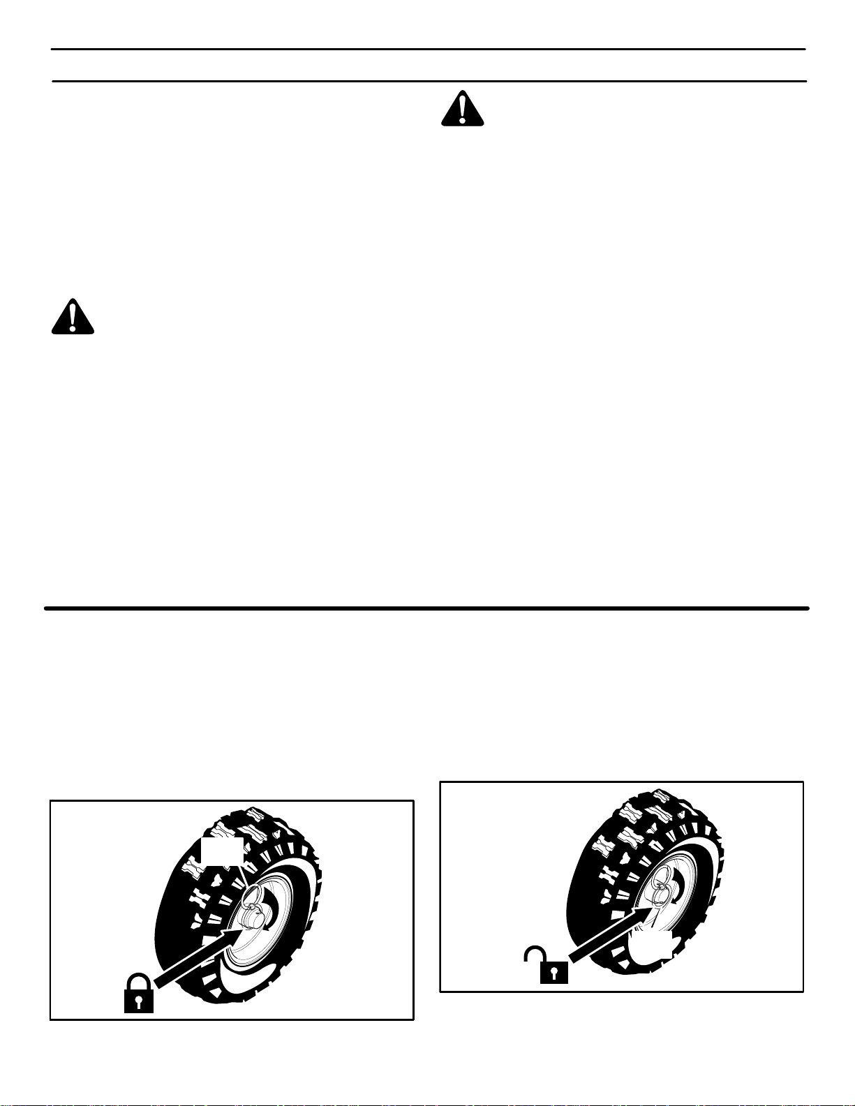
WHEEL LOCK OUT PIN
1. The right wheel is secured to the axle with a klick pin. This
unit was shipped with this klick pin in the locked position.
(Figure 14).
Figure 14
Locked
Position
Klik
Pin
2. For ease of maneuverability when lighter conditions pre-
vail, remove klick pin from wheel locked position and in-
sert into single wheel drive (unlocked) position
(Figure 15). Make sure that the klick pin is in the single
wheel drive position of the axle only and not through the
locked position.
Figure 15
Single
Wheel Drive
Position
(Unlocked)
Klik
Pin
NOTE: Check tire pressure. See side of tire for maximum
inflation. Do not exceed listed maximum pressure.
OPERATION
15
MTF-031071L
HOW TO REMOVE SNOW FROM AUGER
WARNING: Do not attempt to remove snow or
debris that may become lodged in auger with-
out taking the following precautions:
A cleaning stick is attached to the top of the auger housing.
Use the cleaning stick to remove snow from the auger
housing.
Release auger drive lever.
Move throttle lever to stop position.
Remove (do not turn) ignition key.
Disconnect spark plug wire.
Do not place your hands in the auger or discharge
chute. Use the cleaning stick to remove snow.
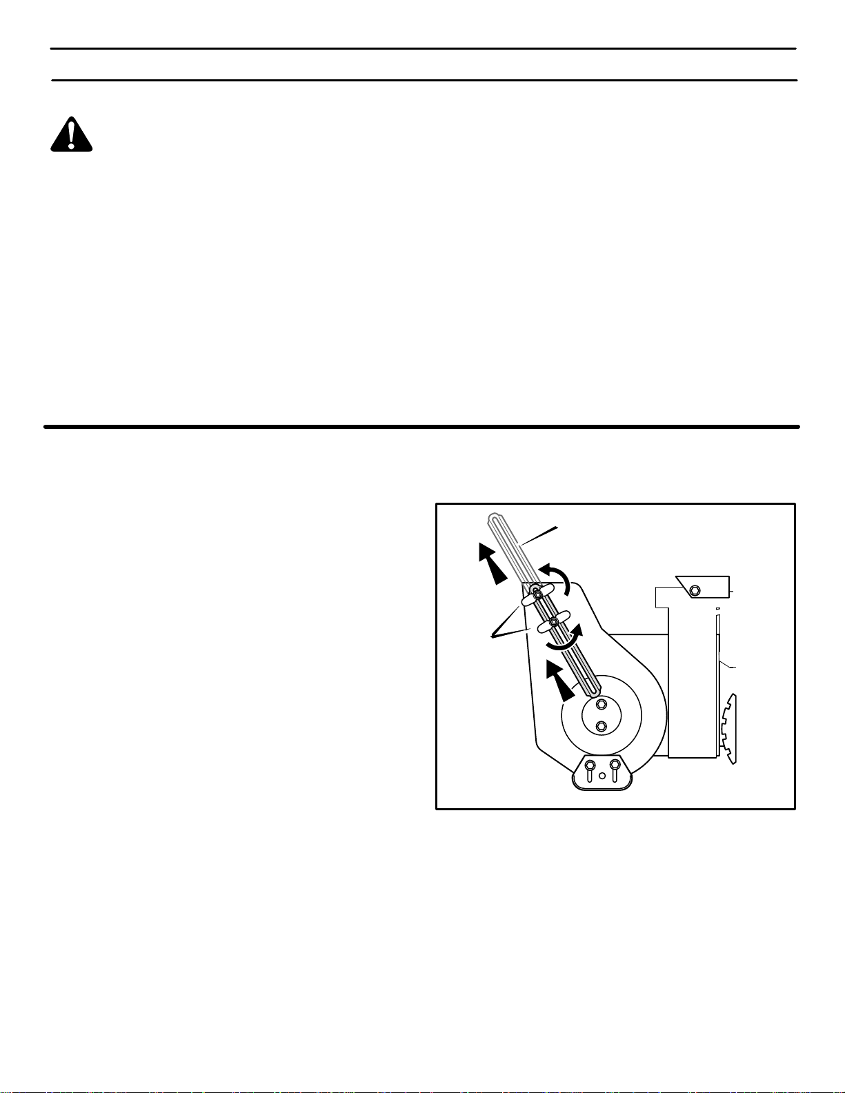
HOW TO SET THE DRIFT CUTTERS
(OPTIONAL ACCESSORY ON SOME MODELS)
Drift cutters are used to cut a path through snow deeper than
the auger housing.
1. Loosen the wingnuts that secure the drift cutters to the
auger housing (see Figure 16).
2. Raise the drift cutters to the desired height.
3. Tighten the wingnuts.
Drift Cutter
Wingnut
Figure 16
OPERATION
16
MTF-031071L
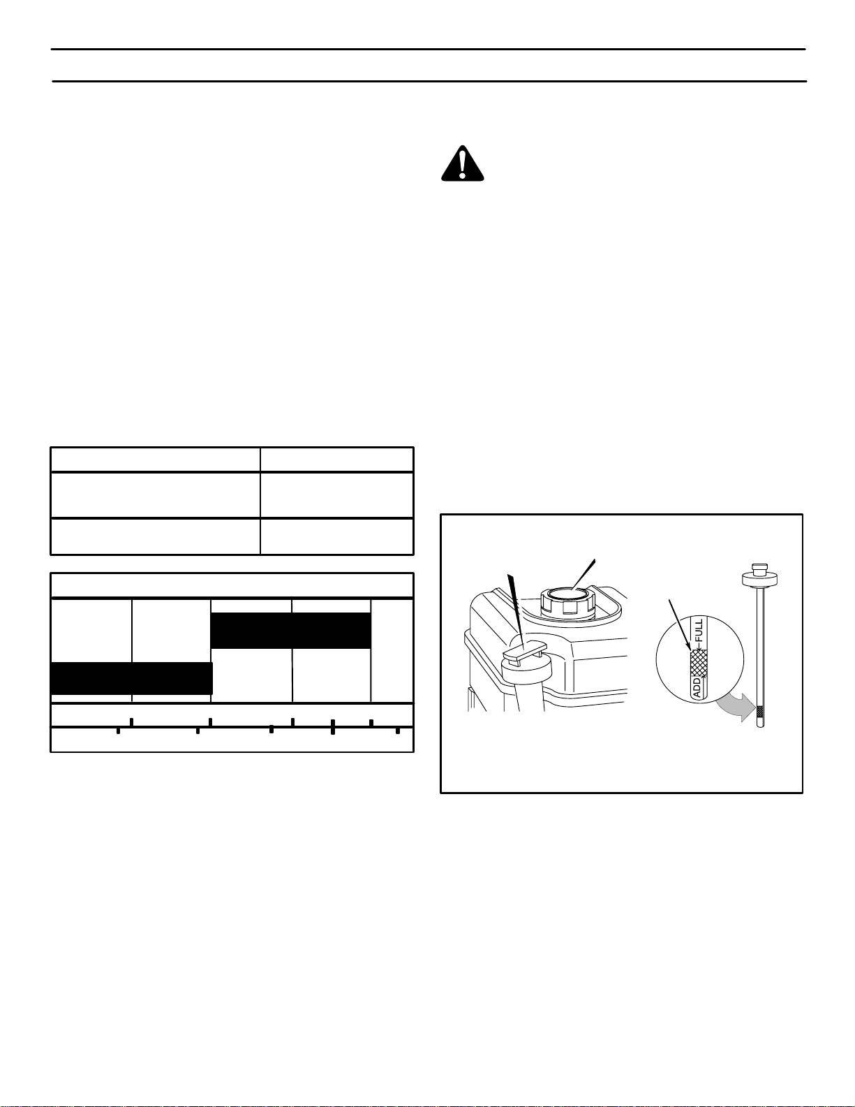
BEFORE STARTING ENGINE
Check the oil
NOTE: The engine was shipped from the factory filled
with oil. Check the level of the oil. Add oil as needed.
1. Make sure the unit is level.
2. Remove the oil fill cap/dipstick. Check the oil.
NOTE: Do not check the level of the oil while the
engine runs.
3. If necessary , add oil until the oil reaches the FULL mark
on the oil fill/cap dipstick (see Figure 17). Do not add too
much oil.
NOTE: For extreme cold operating conditions of 0F
(-18 C) and below, use a synthetic 0W30 motor oil for
easier starting.
NOTE: S.A.E. 5W30 motor oil may be used to make
starting easier in areas where the temperature is 20 F.
(-7 C) to 0F (-18 C).
NOTE: SEE CHART FOR OIL RECOMMENDATION
0F (-18 C) and below
0F (-18 C) and above
TYPE OF OILTEMPERATURE
synthetic 0W30
S.A.E. 5W30
F - 20 0 20 32 40
C -30 -20 -10 0 10
SAE VISCOSITY GRADES
5W30
synthetic 0W30
FILL GAS
1. Fill the fuel tank with fresh, clean, unleaded regular, un-
leaded premium, or reformulated automotive gasoline a-
long with a fuel stabilizer (follow instructions on fuel
stabilizer package). DO NOT use leaded gasoline. We
recommend that fuel stabilizer be added to the fuel each
time that gasoline is added to the fuel tank.
NOTE: Winter grade gasoline has higher volatility to
improve starting. Be certain container is clean and
free from rust or other foreign particles. Never use
gasoline that may be stale from long periods of
storage in the container.
CAUTION: DO NOT use gasoline containing any
amount of alcohol as it can cause serious damage to
the engine or significantly reduce the performance.
2. Check to make sure that spark plug is tightened securely
into engine and spark plug wire is attached to spark plug.
If torque wrench is available, torque plug to 18-23 ft-lbs.
WARNING: Gasoline is flammable. Always use
caution when handling or storing gasoline. Do
not add gasoline to the fuel tank while snow-
thrower is running, hot, or when snowthrower is in an
enclosed area. Keep away from open flame, electrical
sparks and DO NOT SMOKE while filling the fuel tank.
Never fill the fuel tank completely; but fill the fuel tank
to within 1/4-1/2 inch (6.5-12.5 mm) from the top to pro-
vide space f o r t h e e x p a n s ion of the fuel. Always fill fuel
tank outdoors and use a funnel or spout to prevent spil-
ling. Make sure to wipe up any spilled fuel before start-
ing the engine.
Store gasoline in a clean, approved container , and keep
the cap in place on the container. Keep gasoline in a
cool well ventilated place; never in the house. Never
buy more than a 30 day supply of gasoline to assure
volatility. Gasoline Is intended to be used as a fuel for
internal combustion engines; therefore, do not use
gasoline for any other purpose. Since many children
like the smell of gasoline, keep it out of their reach be-
cause the fumes are dangerous to inhale, as well as be-
ing explosive.
FULL
Figure 17
Oil Fill Cap/Dipstick
Fuel Tank
BEFORE STOPPING THE ENGINE
Run the engine for a few minutes to help dry off any moisture
on the engine.
To help avoid possible freeze-up of the starter, proceed as
follows:
Recoil Starter
With the engine running, pull the starter rope with a rapid
continuous full arm stroke three or four times.
NOTE: The normal sound made by pulling the starter
rope will not harm the engine or the starter.
Electric Starter
1. Connect the power cord to the switchbox and then to a
wall outlet.
OPERATION
17
MTF-031071L
2. With the en g i n e r u n n i n g , p ush the starter button and spin
the starter for several seconds.
NOTE: The normal sound made by spinning the
starter will not harm the engine or the starter.
3. Disconnect the power cord from the receptacle first and
then from the switchbox.
TO START ENGINE
Be sure that engine has sufficient oil.
The snowthrower engine is equipped with a recoil starter and
also an electric starter..
WARNING: The electric starter is equipped with
a three-wire power cord and plug designed to
operate on 120 volt AC house hold current. The
power cord must be properly grounded at all times to
avoid the possibility of electric shock which can cause
injury to the operator. Follow all instructions carefully
as set forth below:
Make sure your house has a three-wire grounded sys-
tem. If you are not sure, ask a licensed electrician. If
your house does not have a three-wire grounded sys-
tem, do not use this electric starter under any condi-
tion.
If your house has a three-wire grounded system but a
three hole receptacle is not available to connect the
electric starter, have a three-hole receptacle installed
by a licensed electrician.
WARNING: To connect a 120 volt power cord,
always connect the power cord first to the
switch box located on the engine and then plug
the other end into a three-hole grounded receptacle.
WARNING: To disconnect the power cord, al-
ways unplug the end connected to the three-
hole grounded receptacle first.
COLD ENGINE START
(Engine has not been run recently.)
1. Be sure auger drive clutch lever and traction drive clutch
lever are in the disengaged (RELEASED) position.
2. IN TEMPERATURES ABOVE 0°F (-18°C)
Move throttle control to “FAST” position.
IN TEMPERATURES BELOW 0°F (-18°C)
Move throttle control to “1/2 THROTTLE” position. Be-
fore engaging auger drive clutch lever allow engine to
idle for five minutes to allow engine oil to warm . Failure
to allow engine oil to warm can cause damage to engine.
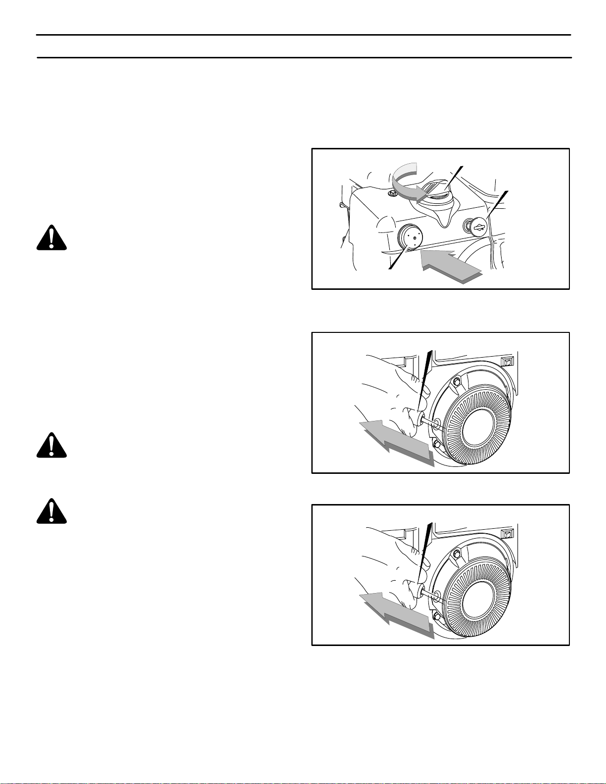
3. Insert key into ignition slot. Make sure it snaps into place
(Figure 18). Do not turn key.
4. Rotate choke knob to the CHOKE position.
5. Push the primer button as follows:
Above 50° F (10° C), DO NOT PRIME.
From 50 ° F (10° C) to 15°F (-10° C), PUSH TWO TIMES.
Below 15° F (-10° C), PUSH FOUR TIMES.
NOTE: Cover the vent hole when as you push the
primer. Remove your finger from the primer vent
hole between pushes.
Choke Knob
Figure 18
Primer Button
Ignition Key
6. (RECOIL START) Pull starter handle (Figure 19) rapidly,
and allow to rewind slowly while maintaining firm grip on
handle.
Recoil Starter Handle
Figure 19
7. (ELECTRIC START) Connect the power cord to the en-
gine and depress the starter button.
Recoil Starter Handle
Figure 20
8. As engine warms up move choke lever to “1/2 choke”
position. When engine does not run smoothly, move
choke lever to the off position.
NOTE: Allow the engine to warm up for several
minutes before blowing snow in temperatures below
0°F (-18 C).
9. Run engine at or near top speed.
 Loading...