


O P E R A T O R ’ S |
M A N U A L |
P A R T S C A T A L O G |
|
|
|
SICKLE BAR
SB 1106
SB 1107
p/n GH 19502091 02 / 2008

2 |
p/n GH 19502091 |

TABLE OF CONTENTS
Description |
|
Description of the sickle bar ............................. |
5 |
Assembly drawing .............................................. |
6 |
Technical specification |
|
Technical specification ....................................... |
7 |
Handling .............................................................. |
7 |
Safety signs |
|
Safety-Alert simbol ............................................. |
8 |
Identification machine ........................................ |
8 |
Machine safety labels ........................................ |
8 |
Machine safety labels and positions |
|
Machine safety labels and positions ................ |
9 |
Preparing the vehicle |
|
Preparing the tractor ..................................... |
10 |
Park vehicle safety ........................................ |
10 |
Stay clear of rotating drivelines .................... |
10 |
Installing |
|
Installing sickle bar on tractor ....................... |
10 |
PTO shaft adaption ....................................... |
12 |
Stability of sickle bar and tractor during |
|
transport ........................................................ |
13 |
Quick Coupler (optional) ............................... |
14 |
Park vehicle safety ........................................ |
14 |
Stay clear of rotating drivelines .................... |
14 |
Removing |
|
Removing sickle bar ..................................... |
15 |
Removing sickle bar with Quick Coupler .... |
15 |
Operating |
|
Operate safetly ............................................. |
16 |
Wear appropriate clothing ............................ |
17 |
Stay clear of rotating drivelines .................... |
17 |
Adapting the mowing bar ............................. |
18 |
Adjustment ..................................................... |
19 |
Mowing ........................................................... |
20 |
Hazard bar ..................................................... |
20 |
Use of lifting device ....................................... |
22 |
Mowing on flat ground ................................... |
23 |
Mowing on sloping ground ........................... |
24 |
Table approximate for choice of the |
|
cutting bar ...................................................... |
25 |
Service Machine Safely |
|
Practice safe maintenance........................... |
26 |
Wear appropriate clothing ............................ |
26 |
Stay clear of rotating drivelines .................... |
26 |
Maintenance .................................................. |
26 |
Service |
|
Lubrication ..................................................... |
28 |
Routine maintenance .................................... |
28 |
Every 2 work hours ........................................ |
28 |
Every 8 work hours ........................................ |
28 |
Every 50 work hours ..................................... |
28 |
Periodically (6 months) ................................ |
28 |
After each mowing job .................................. |
28 |
Cleaning and oiling the cutters .................... |
29 |
Checking the clearance tolerance .............. |
29 |
Storage ........................................................... |
30 |
Extra maintenance ........................................ |
31 |
Replacement of section-holding bar ........... |
31 |
Replacement of sections .............................. |
31 |
Replacement of bar holding removable |
|
tooth ................................................................ |
32 |
Replacement of removable tooth ................ |
32 |
Replacement of belts .................................... |
32 |
Replacement of pulleys ................................ |
32 |
Demolition and disposal |
|
Demolition and disposal .............................. |
33 |
Assembly |
|
Assembly ....................................................... |
34 |
Transport on road |
|
Transport on road .......................................... |
42 |
Spare parts |
|
Spare parts .................................................... |
43 |
Decal kit and location |
|
Decal kit and location ................................. |
54 |
Warranty |
|
Warranty ......................................................... |
56 |
Warranty for replacement parts .................... |
57 |
p/n GH 19502091 |
3 |

TO THE DEALER:
Assembly and proper installation of this product is the responsibility of the Frontier dealer. Read manual instruction and safety rules. Make sure all items on the Dealer’s Pre-Delivery Check List in the Operator’s Manual are completed before releasing equipment to the owner.
The dealer must complete the Warranty Registration, located on the Frontier website. Warranty claims will be denied if the Warranty Registration has not been completed.
TO THE OWNER:
Read this manual before operating your frontier equipment. The information presented will prepare you to do a better and a safer job. Keep this manual handy for ready reference. Require all operators to read this manual carefully and become acquainted with all the adjustment and operating procedures before attempting to operate. Replacement manuals can be obtained from your selling dealer.
The equipment you have purchased has been carefully enginereed and manufactured to provide dependable and satisfactory use. Like all mechanical products, it will require cleaning and upkeep. Lubricate the unit as specified. Observe all safety information in this manual and safety decals on the equipment.
For service, your authorized Frontier dealer has trained mechanics, genuine Frontier service parts, and the necessary tools and equipment to handle all your needs.
Use only genuine Frontier service parts.Substitute parts will void the warranty and may not meet standards required for safe and satisfactory operation. Record the model number and serial number of your equipment in the spaces provided:
Model: _________________________________ Date of Purchase _____________________________
Serial Number: (see Safety Decal section for location) _______________________________________
Provide this information to your dealer to obtain correct repair parts.
Throghout this manual, the term IMPORTANT is used to indicate that failure to observe can cause damage to equipment. The terms CAUTION, WARNING and DANGER are used in conjunction with the Safety-Alert Symbol, (a triangle with an esclamation mark), to indicate the degree of hazard for items of personal safety.
DANGER.
 WARNING
This Safety-Alert Simbol indicates a hazard and means ATTENTION! BECOMEALERT! YOUR SAFETY IS INVOLVED!
Indicates an imminently hazardous situation that, if not avoided, will result in death or serious injury.
Indicates a potentially hazardous situation that, if not avoided, could result in death or serious injury, and includes hazards that are exposed when guards are removed.
CAUTION |
Indicates a potentially hazardous situation that, if not avoided, |
|
may result in minor or moderate injury. |
IMPORTANT |
Indicates that a failure to observe can cause damage to |
|
equipment. |
NOTE |
Indicates helpful information. |
|
|
4 |
p/n GH 19502091 |

DESCRIPTION
Description of the sickle bar
This agricultural implement can only operate by means of a cardan shaft applied to the pto of an agricultural tractor equipped with lift and universal three-point hitch. Since it is movable, the mowing machine can be easily mounted on tractors with different gauges or on tracked vehicles (Fig.
1). The two-motion tooth-blade system used in mowing machines, makes possible a scissors cut which leads to a higt speed operation on a any crop. The original tooth-blade motion guarantees a sharp and clean cut on any type of grass, be it damp or flattened. It is thanks to the total absence of soil which this mowing system does not raise, sharp because the stems are not frayed. The sickle bar may also be used with the cutting arm tilted for working on canals, ditches and embankments (Fig. 2 and 3).
ATTENTION
The sickle bar is suitable only for the uses indicated. Any other use different from that described in these instructions could cause damage to the machine and represent a serious hazard for the user.
It is therefore advisable to strictly comply with the following instructions in order to prevent faults which could jeopardize the correct and long-lasting operation of the implement.
Compliance with the instructions in this handbook is also important since the Manufacturer declines all and every responsibility for damage to persons or property caused by negligence and failure to comply with these instructions.
The Manufacturer shall, however, remain at the customers’ disposal for immediate and thorough assistance together with anything else that may be required in order to ensure the correct operation and maximum efficiency of the implement.
The Manufacturer reserves the right to make any modifications and improvements to the implement as may be considered opportune, without being obliged to immediately inform the user.
Fig. 1
Fig. 2
Fig. 3
p/n GH 19502091 |
5 |
|
|
DESCRIPTION |
||
|
|
|
|
|
|
|
|
|
|
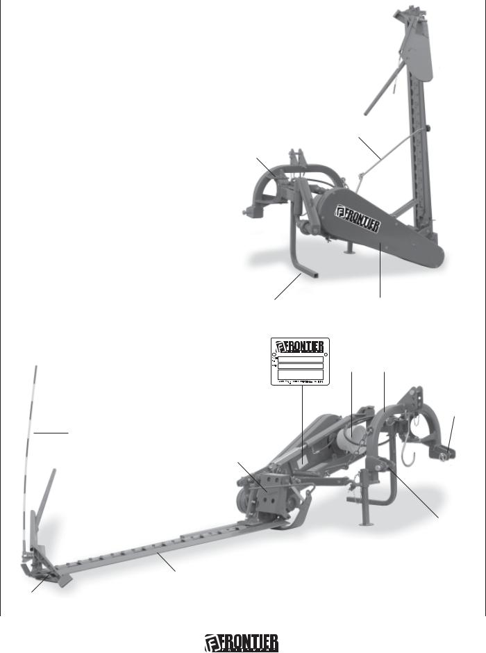
Assembly drawing |
|
|
|
|
1 |
External shoe; |
|
|
|
2 |
Mowing guide; |
|
|
2 |
|
||||
3Cutting arm;
4Upper 3rd point hitches;
5Gauge varying articulation;
6 |
Chassis; |
4 |
|
|
3 |
|
|
||||||
|
|
|
|
|
||
7 |
Tirant; |
|
|
|
|
|
8 |
Lower 3rd point hitches; |
|
|
7 |
|
|
9 |
Hazard bar; |
5 |
|
|
|
|
10 |
Support; |
|
|
|
|
|
|
|
|
|
|
||
11Identification label;
12Cover;
13Protective casing for connecting-rod systems;
14Support;
15Hinge (pivot point);
16Blade guard;
17PTO.
10 |
12 |
17 6
11
8
9
13
|
|
8 |
|
|
|
|
|
15 |
14 |
||
16 |
|
|
|
1 |
|
|
Fig. 4 |
|
|
|
|
|
|
|
|
|
|
|
|
6 |
|
|
p/n GH 19502091 |
TECHNICAL SPECIFICATIONS
SB1106 SB1107
|
/16 |
68 |
15 |
/64 |
|
80 |
45 |
|
inches inches
Model Work/width |
Tractor |
Weight |
Tooth |
Sections |
Side |
Work |
PTO |
Hitch |
Acoustic power level Continuous equivalent acoustic |
|
inches |
HP |
lbs. |
number |
number |
Drive |
speed |
Input |
|
uttered bay machine radiation pressure level (Weighed |
|
|
min. - max. |
|
|
|
|
miles/h |
speed |
|
(Weighed A) LWA |
A) in the "worker’s position" LpA |
SB 1106 |
68.9 |
25 |
- 50 |
456 |
12 |
24 |
Belts |
6.2 |
7.5 |
540 |
|
110.7 dB |
91.7 dB |
|
|||||||||||||
|
|||||||||||||
|
|
|
|
|
|
|
B-93 |
|
|
|
Quick coupler |
|
|
|
|
|
|
|
|
|
|
|
|
|
|
||
|
|
|
|
|
|
|
|
|
|
|
|
|
|
SB 1107 |
80.7 |
25 |
- 50 |
470 |
14 |
28 |
Belts |
6.2 |
7.5 |
540 |
|
110.7 dB |
91.7 dB |
|
|||||||||||||
|
|||||||||||||
|
|||||||||||||
|
|
|
|
|
|
|
B-93 |
|
|
|
Quick coupler |
|
|
|
|
|
|
|
|
|
|
|
|
|
|
||
Handling
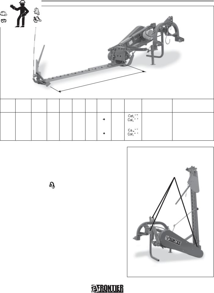
During handling operations, use suitable personal protection device:
If the machine is handled, it must be lifted by hooking (Fig.
5) onto the appropriate holes with a suitable winch or crane of sufficient capacity. Because of the danger involved, this operation should be carried out by trained and responsible personnel. The mass of the machine is on the identification label (11 - Fig. 4).
Stretch the rope to keep the machine level.
The lifting points can be detected by finding the “hook” symbol (8 - page 9).
During handling operations make sure the implement has the required safety devices and guards.
Fig. 5
p/n GH 19502091 |
7 |

SAFETY SIGNS
Safety-alert symbol
Read and recognize safety information.
Be alert to the potential for personal injury when you see this safety-alert symbol.
On your machine safety labels, the words DANGER, WARNING, and CAUTION are used with a safety symbol. DANGER identifies the most serious hazards. In this manual, the word CAUTION and this symbol call attention to safety messages.
Identification machine
Identification label
Machine safety labels
1) CAUTION: AVOID INJURY
• Read Operator’s Manual
•Ballast power unit per operator’s manual
•Know location and function of controls
• Keep all shields in place
•Stay clear of power driven parts
•Never carry riders
•Keep people and pets a safe distance away from machine
BEFORE DISMOUNTING OR SERVICING
•Shut off engine and remove key
•Lock brake for park
•Lower or block up machine
2)CAUTION
1 Keep all shields in place.
2 Disengage and shut off all engine and/or motor power before servicing or unclogging machine. 3 Keep hands, feet and clothing away from power-driven parts.
3)DANGER: CRUSHING AND PINCH POINTS
MOVING MACHINERY PARTS CAN PINCH OR CRUSH OR FALL, WHICH MAY CAUSE INJURY OR DEATH.
4)DANGER
Entanglement in rotating driveline can cause serious injury or death. Keep all shields in place.
Avoid contact with rotating parts.
5)DANGER: KEEP AWAY - SHARP BLADES
•Do not put hands or feet near the cutterbar. Blade contact can result in serious injury.
•Stay away until all motion has stopped and the mower is securely blocked up.
•Keep fingers clear of cutterbar when folding cutterbar for transport.
6)CAUTION
Operate only with 540 rpm PTO
8 |
p/n GH 19502091 |

MACHINE SAFETY LABELS AND POSITIONS
1 |
2 |
3 |
|
|
1. Keep all shields in place. |
2. Disengage and shut off all engine
and/or motor power before
servicing or unclogging machine.
3. Keep hands, feet and clothing
away from power-driven parts.
CRUSHING AND PINCH POINTS
MOVING MACHINERY PARTS CAN PINCH OR CRUSH OR FALL -
WHICH MAY CAUSE INJURY OR DEATH.
5
9
1 2 3 4
|
6 |
8 |
3 |
4 |
|
7 |
|
7)High noise level. Use adequate acoustic protection.
8)Coupling point for lifting.
9)Greasing point.
4
Entanglement in rotating driveline can cause serious
injury or death.
Keep all shields in place.
Avoid contact with rotating parts.
5
KEEPAWAY
SHARPBLADES
-Donotputhandsorfeetnearthecutterbar. Bladecontactcanresultinseriousinjury. -Stayawayuntilallmotionhasstoppedand themowerissecurelyblockedup.
-Keepfingersclearofcutterbarwhenfolding cutterbarfortransport.
6
Operate only with 540 rpm PTO
7
8
9
p/n GH 19502091 |
9 |
PREPARING THE VEHICLE
Preparing the tractor
 CAUTION: Avoid injury. Proper ballastings is required for safe operation of your sickle bar IMPORTANT: Refer to the tractor operator manual for proper ballasting information and tire inflation
•A 540 rpm PTO
•Refertothetractoroperatorismanualforcorrectballastingandtirepressure,dependingoninstalledequipment.
Park vehicle safety
•Stop vehicle on a lever surface, not on a slope.
•Disengage PTO.
•Engage the park brake.
•STOP the engine.
•Remove the key.
•Before you leave the operator’s seat, wait for engine and all moving parts to STOP.
Stay clear of rotating drivelines
Entanglement in rotating driveline can cause serious injury or death:
•Wear close fitting clothing.
•STOP the engine and be sure PTO driveline is stopped before getting near it.
Installing sickle bar on tactor
The sickle bar can be hitched to I, II or quick coupler category tractor equipped with a universal three-point coupling.
DANGER
Application of any implement to a tractor is a very dangerous operation and must only be carried out with the utmost care in compliance with the instructions.
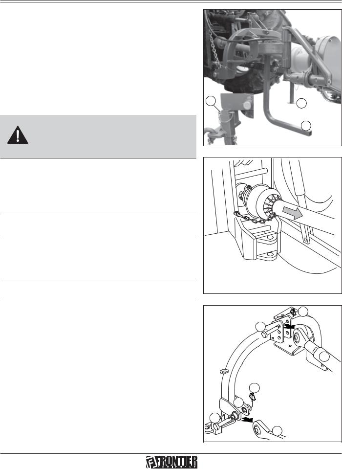
The correct tractor/sickle bar position is established by setting the implement at such a distance from the tractor that the universal coupling remains 2-4 inches from its maximum closing position. Now proceed in the following way:
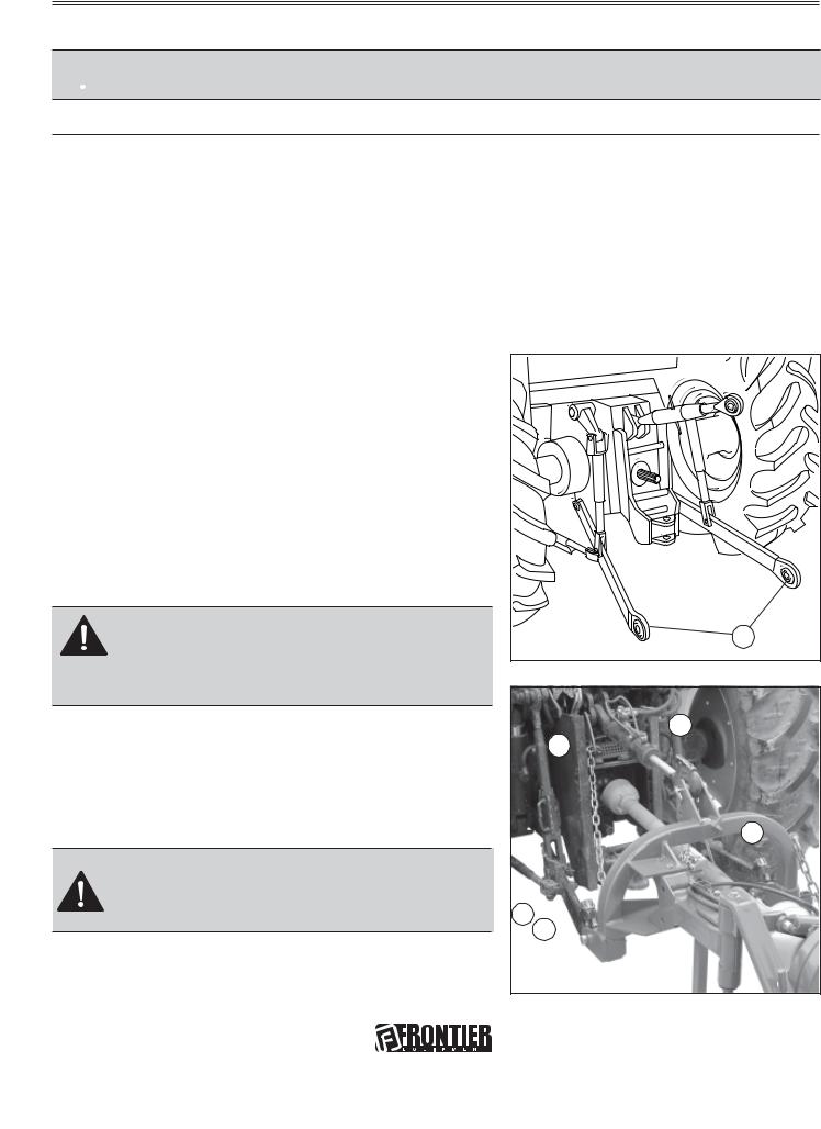
1.Back tractor into position and align draft links (A, Fig. 6) with draft link brackets on sickle bar.
CAUTION: Before you work around hitch:
•STOP engine.
•LOCK park brake.
•FIRMLY block mower on horizontal surface.
2.Connect the upper third-point and correctly regulate by adjusting the top link (B, Fig. 7). Place plate (C, Fig. 7) at the left side of the hitch integral with the same pin. Lock in place with the snap-in split pins (D, Fig. 8).
Fig. 6 |
A |
|
|
|
B |
|
C |
|
F |
H E |
|
Fig. 7
10 |
p/n GH 19502091 |
INSTALLING
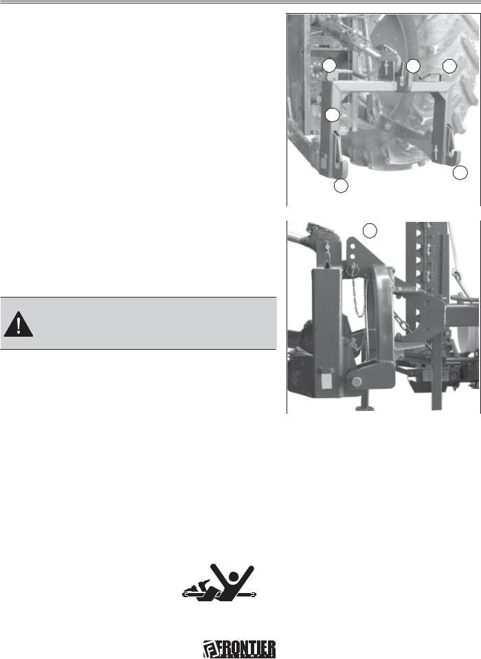
3.Hook the oscillating arms of the tractor to pins (E and F,
Fig. 7). Lock in place with the snap-in split pins (G Fig. 8).
4.Lock the lift links using the relative chains (H, Fig. 7) and couplings parallel to the tractor. This operation must be carried out to prevent the machine from moving in a horizontal direction.
D |
G |
Fig. 8 |
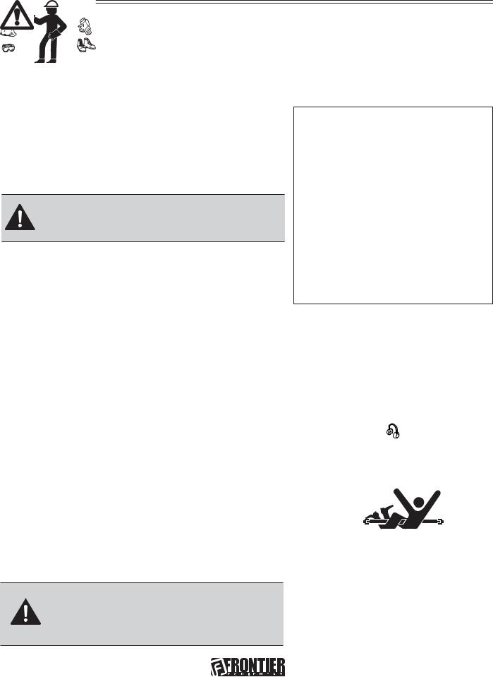
5. Install PTO shaft to tractor (Fig. 9).
IMPORTANT: Sickle bar MUST BE level front to rear.
Make sure PTO shaft is locked on the tractor PTO prior to engagement (I). Check that the guard (L) is free to turn and fix it with the relative latch (L1).
6.Remove the guard over the cutters (16, Fig. 4) and remove the tirant (7, Fig.4).
7.Lift-up sickle bar.
8.Remove spring locking pin (M, Fig. 10) from parking stand.
9.Remove support (N and O, Fig. 10) and remount them, upside-down in their seat .
10.Fasten with spring locking pin (M, Fig. 10).
I |
L |
L1 |
Fig. 9 |
N |
M |
O |
Fig. 10
p/n GH 19502091 |
11 |
|

INSTALLING
PTO shaft adaption
The PTO shaft, supplied with the machine, is of standard length. Therefore it might be necessary to adapt the PTO shaft. Consult your dealer for the eventual adaptation.
CAUTION
• WhenthePTOshaftisfullyextended,thetwotubes mustoverlapbyatleast6 inches (PFig.11).When fully inserted, the minimum play must be 137/64 inches (Q Fig.11).
•Iftheimplementisusedonanothertractor,always check the above and that the guards copletely covertherotatingpartsofthePTO shaft.
ATTENTION
Comply with the manufacturer's instructions when transportingthemowingmachine.
P
min. 6 inches
Max
Q
min. 137/64 inches
Min
Fig. 11
• The equipment installed can only be controlled by means |
|
|
of the PTO shaft complete with the necessary overload |
|
|
safety (i.e. clutch) devices and guards fastened with the |
|
|
appropriate chain. |
|
|
• Only the PTO shaft supplied by the Manufacturer must be |
|
|
used. |
|
|
• The engine must not be running when installing and |
|
|
removing the PTO shaft. |
Fig. 12 |
|
• Care must be taken regarding the safety and correct |
||
|
||
assembly of the PTO shaft. |
|
|
• Use the chain provided to stop the PTO shaft from rotating. |
|
|
• Always check carefully that the PTO shaft guard is always |
|
|
in position, both during transportation and operation. |
|
|
• Frequently and set intervals check the PTO shaft guard, it |
|
|
must always be in excellent condition. |
|
|
• Before engaging the PTO, check that the set rpm |
|
|
corresponds to that indicated by the sticker on the |
|
equipment. |
R |
•Before inserting the PTO, make sure that there are no people or animals nearby and that the rpm selected corresponds to that permitted. Never exceed the maximum admissible speed.
•Watch out for the rotating universal joint.
•Do not insert the PTO with the engine off or synchronized
with the wheels. |
Fig. 13 |
•Always disconnect the PTO when the cardan shaft is at too wide an angle (never more than 10°,Fig. 12) and when it is not being used.
•Only clean and grease the PTO shaft when the power take-off is disconnected, the engine is off, the hand brake pulled and the key removed.
•When not in use, place the PTO shaft on the support provided for it.
•After having dismantled the PTO, place the protective cover on the PTO shaft (R, Fig.13).
|
12 |
p/n GH 19502091 |

INSTALLING
Stability of sickle bar and tractor during transport
When a sickle bar is coupled to a tractor, so becoming an integral part of it for the purposes of road travel, the stability of the sickle bar-tractor complex may change and cause driving or operating difficulties
(rearing up or side-slipping of the tractor). The condition of equilibrium can be restored by placing a sufficient number of ballasts on the front of the tractor so that the weights on the two tractor axles are distributed sufficiently evenly. To work in safety the instructions given in the highway code should be followed; these prescribe that at least 20% of the weight of the tractor alone should be borne by the front axle and that the weight on the arms of the hoist should not be more than 30% of the weight of the tractor itself. These factors are summarized in the following formulas:
Z > (M x s)-(0.2 x T x i) (d+i)
The amount of ballast that should be applied according to the formula is the minimum required for circulation on the road. If for reasons of tractor performance or to improve the set-up of the sickle bar during operation it is thought necessary to raise these values, please refer to the registration document of the tractor to check its limits. When the formula for calculating the ballast gives a negative result it will not be necessary to add any weight. In any case, as long as the limits of the
tractor are respected, a suitable quantity of weights may be applied in order to ensure greater stability during travel. The symbols have the following meanings:
M T Z i d s
Kg
Kg
Kg
m
m
m
Mass weighing on arms off hoist with full load (Technical data table)
Mass of tractor
Total mass of ballast
Tractor wheelbase, that is, the horizontal distance between the tractor axles
Horizontal distance between the centre of gravity of the ballast and the front axle of the tractor
Horizontal distance between the centre of gravity of the operating machine and the back axle of the tractor
169/64
inches
Fig. 14
(please see Fig. 14 for reference):
p/n GH 19502091 |
13 |
|
INSTALLING
Quick Coupler (optional)
1)Install hitch Quick Coupler (S, Fig. 15) on the tractor (see tractor operator manual).
2) Parking the sickle bar on a flat and compact ground |
V |
T |
V |
|
|
|
|
supported by the relative supports. Then slowly move |
|
|
|
the tractor back until the Quick Coupler (S) is in range |
|
|
|
with the point hitches (T and U, Fig. 15). |
S |
|
|
|
U |
|
|
U |
|
|
Fig. 15 |
|
3) Raise the Quick Coupler (S, Fig. 15) and make sure |
|
|
|
||
Z |
||
that sickle bar hitch is in the right position (Z, Fig. 16). |
||
|
CAUTION: Before you work around hitch:
•STOP engine.
•LOCK park brake.
•FIRMLY block mower on horizontal surface.
Park vehicle safely |
Fig. 16 |
|
• Stop vehicle on a level surface, not on a slope. |
||
|
||
|
•Disengage PTO.
•Engage the park brake.
•STOP the engine.
•Remove the key.
•Before you leave the operator’s seat, wait for engine and all moving parts to STOP.
Stay clear of rotating drivelines
Entanglement in rotating driveline can cause serious injury or death:
•Wear close fitting clothing.
•STOP the engine and be sure PTO driveline is stopped before getting near it.
|
14 |
p/n GH 19502091 |
REMOVING
Removing sickle bar
The sickle bar must be set-up on flat and compact ground, supported by the relative supports (A and B, Fig. 17).
1.Raise sickle bar.
2.Put parking stand (A and B, Fig. 17) in the DOWN position: install spring locking pin in order to secure parking stand (C, Fig. 17).
3. Lower sickle bar to the ground. |
|
C |
|
|
|
CAUTION: Before you work around hitch: |
|
|
• STOP engine. |
|
|
• LOCK park brake. |
|
|
• FIRMLY block mower on horizontal surface. |
|
|
A
B
Fig. 17
4. |
Unhook the PTO schaft (, Fig. 18) from the tractor and |
|
|
|
put in on the special hook. |
|
|
5. |
Remove quik-lock pin (D, Fig. 19) and pin (E, Fig. 19) |
|
|
|
from center link (F, Fig. 19). |
|
|
NOTE: Put quik-lock pins and pins back into brackets |
|
||
|
on sickle bar for storage. |
|
|
6. |
Remove draft links (J, Fig. 19) from draft link brackets (G, |
|
|
|
Fig. 19) by removing quiklock pins (H, Fig. 19) and pins |
|
|
|
(I, Fig. 19). |
|
|
NOTE: Put quik-lock pins and pins back into brackets |
Fig. 18 |
||
|
on sickle bar for storage. |
|
|
7. |
Drive tractor forward slowly. |
D |
|
|
|
E |
|
Removing sickle bar with Quick Coupler |
F |
||
|
|||
1. |
Raise sickle bar. |
|
|
2. |
Put parking stand (A and B, Fig. 17) in the DOWN |
H |
|
|
position: install spring locking pin in order to secure |
||
|
parking stand (C , Fig. 17). |
G |
|
3. |
Lower sickle bar to the ground. |
||
I |
|||
4. |
Raise the two Quick Coupler levers (V, Fig. 15) to unloch |
||
|
sickle bar (Quick Coupler Figure, page 14). |
J |
|
5. |
Lower Quick Coupler till further free the sickle bar. |
||
Fig. 19 |
|||
p/n GH 19502091 |
15 |
||

OPERATING
Operate safely
Carefully read all the instructions before using the machine; if in doubt, contact the technicians of the Manufacturer’s dealer. The manufacturer declines all responsibility for the non-observance of the safety and accident prevention regulations described below.
General norms
1)Pay close attention to the danger signs in this manual and on the sickle bar.
2)The labels with the instructions attached to the machine give abbreviated advice for avoiding accidents.
3)Carefully observe, with the help of the instructions, the safety and accident prevention regulations.
4)Avoid touching moving parts in any way whatsoever.
5)Any work on and adjustment to the machine must always be done with the engine switched off and the tractor blocked.
6)People or animals must not, under any circumstances, be transported on the equipment.
7)It is strictly prohibited to drive the tractor, or allow it to be driven with the equipment attached by persons not in possession of a driver’s license, an expert or in poor conditions of health.
8)Before starting the tractor and the equipment, check that all safety devices for transport and operation are in perfect working order.
9)Before starting up the equipment, check the area surrounding the machine to ensure that there are no people, especially children or pets, nearby, and ensure that you have excellent visibility.
10)Use suitable clothing. Avoid loose clothing or garments with parts that could in any way get caught in the rotating or moving parts of the machine.
11) Before starting work, familiarize yourself with the control devices and their functions.
12)Only start working with the equipment if all the protective devices are in perfect condition, installed and in the safe position.
13)It is absolutely prohibited to stand within the machine’s radius of action where there are moving parts.
14)It is absolutely forbidden to use the equipment without the guards.
15)Before leaving the tractor, lower the implement coupled to the lift unit, stop the engine, engage the hand brake, remove the ignition key from the control panel, cover the cutters and outer skid with the relative guards. Raise the mowing bar (transport protection) according with the instructions given in this handbook.
16)The driver’s seat must never be left when the tractor engine is running.
17)Before operating the mowing machine, check that the support struts (A and B, Fig. 17 page 15) have been removed from underneath the implement. Make sure that the sickle bar has been correctly mounted and adjusted. Check that the machine is in perfect order and that all components subject to wear and deterioration are efficient.
18)Before releasing the equipment from the third point attachment, put the hoist command lever into the locked position and lower the support feet.
19)Only operate during daylight or with proper artificial light.
20)All operations must be carried out by expert personnel, equipped with protective gloves, in a clean and dust-free environment.
21)Do not climb onto the machine while it is running, even if it is stationary.
22)Before approaching the mowing bar, disengage the pto, switch off the tractor, engage the parking brake and check that the cutters are at a complete standstill.
23)The coupled implement may only be controlled through the PTO shaft complete with the necessary safety devices for overloads and with the guards fixed with the relative latch.
24)During maintenance and work operations, make sure that no other person goes near the tractor and the implement and accidentally works the controls with the risk of causing injury to persons and damage to property.
25)As a precaution, always set adeguate supports under the implement during assembly, servicing, cleaning or assembly work with the mowing bar raised.
16 |
p/n GH 19502091 |
OPERATING
26)DO NOT wear radio or music headphones while operating the machine. Safe operation requires your full attention.
27)DO NOT operate the tractor and sickle bar when you are tired or ill.
Tractor hitch
1)Hook the equipment to a suitable, sufficiently-powered tractor by means of the appropriate device
(lifter), in conformity with applicable standards.
2)The class of the equipment attachment pins must be the
same as that of the lifter attachment.
3)Take care when working within the range of the lifting arms as this is a very dangerous area.
4)Be very careful when hooking and unhooking the equipment.
5) It is absolutely forbidden to stand between the tractor and linkage for acting the lifting controls from the outside (Fig. 20).
6) It is absolutely forbidden to stand in the space between the tractor and the equipment (Fig. 20) with the engine running.
7) The attaching of additional equipment onto the tractor brings about a different distribution of weight on the axles.
Check the compatibility of the tractor performance with the weight that the mower transfers onto the three-point linkage. If in doubt consult the tractor Manufacturer.
8) Comply with the maximum admissible weight for the axle, the total mobile weight, transport regulations and the highway code.
Wear appropriate clothing
•Wear close fitting clothing and safely equipment appropriate for the job.
•Loud noise can cause impairment or loss of hearing, wear a suitable
protective device such as earplugs.
Stay clear of rotating drivelines
Entanglement in rotating driveline can cause serious injury or death:
• Wear close fitting clothing
• Stop the engine and be sure PTO shaft is stopped before getting near it.
CAUTION: Before you work around hitch:
• STOP engine.
• LOCK park brake.
• FIRMLY block mower on horizontal surface.
p/n GH 19502091 |
17 |
OPERATING
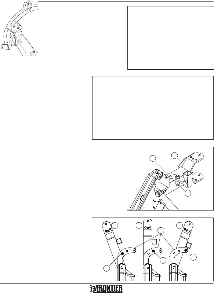
Adapting the sickle bar
To ensure optium use, the sickle bar must completely project from the tractor (Fig. 21); three situations are shown in the
Figure 22:
1)hitching to a tractor normally used for mowing jobs;
2)hitching to a large tractor;
3)hitching to a small tractor or to certain types of tracked vehicle.
Fig. 21
Fig. 22
When the frame joint is moved (A, Fig. 23), the position of the stop bushing (C, Fig. 23) of the cylinder linkage must consequently be changed, according to the cases shown in figures 23 and 24.
|
Fig. 23 |
B |
A |
|
|
|
C |
Connections between frame joint and |
A1 |
A2 |
|
Fig. 24 |
stop bushing for the movement of the |
B |
A3 |
||
mowing bar. |
|
|
|
|
|
|
|
C2 |
C3 |
|
|
|
|
|
|
C1 |
|
|
|
18 |
|
|
|
p/n GH 19502091 |
 Loading...