


O P E R A T O R ' S M A N U A L
ROTARY RAKE
 RR2109
5PQ990104 (08/28/2012)
To the Owner;
Thank-You for choosing a quality product from Frontier Equipment. We strive to give you the best equipment and the best level of service of any company. With a little care and maintenance this machine will do your work for you for many years. In this manual, we make an effort to get you better acquainted with the machine so you can achieve maximum performance. We design and build all of our equipment with the end user in mind so we welcome any suggestions or ideas for improvement. Please note that it is within our rights to make changes or improvements to our equipment without updating the equipment that was manufactured before the change took place.
Please take a few minutes to fill out the area below. This information will be valuable to you when ordering parts or requesting service from your dealer.
Dealer Name:_____________________________
Dealer Phone Number:______________________
Service Manager/Technician:_________________
Model# and Description:_____________________
Serial Number:____________________________
Date of Purchase:__________________________

TABLE OF CONTENTS
Introduction ……………………………………………………………… 2
Rake Serial Number ………………………..……………… 2
Specifications ………………………………………………… 2
Safety ………………………………………………………...……………… 3 Power Source Safety ………………………………………… 3
Safety Decals …………………….…………..……………… 4 Driveline Safety …………………….…………..…………..… 5
Dealer Setup ……………………………………………..……………… 6
Hitching ……………………………………………………..……………… 8 Tractor Requirements ……………………….……………… 8 Hitching ………………………………………..……………… 8
Transporting ……………………………………………………………… 10
Field Transport ……………………………………………… 10 Road Transport ……………………………………………… 10
Height and Level Adjustment ………………………....………… 11 Height Adjustment ………………………………………..… 11 Leveling the Rake ………………………………………… 11
Hay Curtain Adjustments ………………………………………… 12
Operating ……………………………………………………………….… 13 Field Dangers …………………………………………….… 13
Lubrication …………………………………………………………….… 14
Gearbox Lubrication ……………………………………..… 14 PTO Lubrication …………………………………………..… 15 General Lubrication ……………………………………...… 15
Maintenance …………………………………………………………..… 16
Storing your Rake …………………………………………………… 16
Torque Specifications ……………………………………………… 17
Standard Torque Chart …………………………………..… 17
Metric Torque Chart ………………………………………… 18
Warranty ………………………………………………………………...… 19
Illustrated Parts Breakdowns …...……………………………...… 20
Tongue & Main Frame …….……………………………… 21
Guards …………………..…………………………………… 22 Gearbox & Tine Arm …..…………………………………… 23
Axle Assembly ……………………………………………… 24
Rotary Gearbox …….……………………………………… 25
PTO Shaft ……………...…………………………………… 26
Decals & Reflectors …..…………………………………… 27
1

INTRODUCTION
Thank-You for choosing the Frontier Rotary Rake. Your rake is the result of years of research and development work. This Operator’s Manual will familiarize the operator with the safety and operation of the machine. Included are complete instructions for assembly, operation, lubrication, and maintenance procedures. Understanding and following these procedures will result in years of maximum performance from your Frontier Rake.
Read entire manual before operating. Failure to follow the instructions outlined in this manual may result in personal injury and/or damaged equipment, and could void the warranty.
Rake Serial Number
The rake’s serial number can be found near the front on the main frame of the rake. Please use this number when requesting service, seeking information, or ordering parts. For the operator’s convenience, space to record the serial number, model number, purchase date, and dealer has been provided inside the front cover of this manual.
All pictures and instructions in this manual assume that the right and left side of the machine are that of someone standing behind the rake facing forward.
Specifications
Specifications |
RR2211 |
|
RR2109 |
Working Width |
13' (4.3m) |
|
10' 8" (3.2m) |
Raking Width |
11' (3.3m) |
|
9' (2.7m) |
Transport Width |
59" (1.5m) |
|
9' 4" (2.8m) |
Gear Box |
Enclosed Oil Bath |
||
Gear Reduction |
|
9.7 to 1 |
|
Tine Arms |
11 |
|
9 |
Double Tines per Arm |
4 |
|
3 |
PTO/HP Required |
40 HP - 540 RPM |
|
30 HP - 540 RPM |
Direction of Raking Action |
|
Left |
|
Hydraulic Requirement |
|
1200 psi |
|
Weight |
1550 lbs. |
|
1050 lbs. |
Tandem Axle Beam |
|
Standard |
|
Tires |
18.5 x 8 Flotation Tires on 4-Bolt Painted Wheels |
||
2

SAFETY
This symbol precedes specific safety instructions throughout this manual. When reading the manual pay close attention to the information that follows this symbol.
FAILURE TO FOLLOW INSTRUCTIONS IN THIS MANUAL COULD RESULT IN PERSONAL
INJURY OR DEATH. READ ENTIRE MANUAL BEFORE OPERATING ROTARY RAKE.
Keep hands, feet and clothing away from the machine’s input power take-off (PTO) and any other moving parts until the machine has been shut down and the power source has been locked out. (Refer to Power Source Safety)
Do not adjust, unclog, lubricate, or service the machine until it has been shut down and the power source has been locked out. (Refer to Power Source Safety)
 Do not lubricate or adjust the machine while it is in motion.
 Support the rake securely while working under it.
Do not stand between the tractor and the rake while attaching or detaching the rake unless the tractor engine is shut off and the parking brake has been set.
Be certain all bystanders and animals are a safe distance away from the rake before raising or lowering it. Never allow anyone to ride on the rake or the tractor.
When transporting, never exceed a speed of 20 MPH (32kkm/hr) and avoid sudden turns which may compromise the operator’s control of the tractor.
 Be constantly aware of the location of the ends of the rake to avoid collision with other objects.
When moving the rake on public roads use the proper reflectors, lights, and slow moving vehicle signs required by local government agencies.
Power Source Safety
Do not use a power take-off (PTO) shaft without a rotating shield in good working order. Make sure drive system safety shields are in place for both the power source and the rake.
 The rake input PTO must be securely attached to both the power source and the input shaft.
 Do not overextend the input PTO shaft.
 Make sure PTO is disengaged before starting power source.
 PTO shield chains must be attached to the tractor and the rake to keep the shield from rotating.
3

SAFETY CONT’D
Safety Decals
Decals and reflectors are for the protection of yourself and others. If they are missing, faded, or not readable, get replacements from your dealer immediately.
4
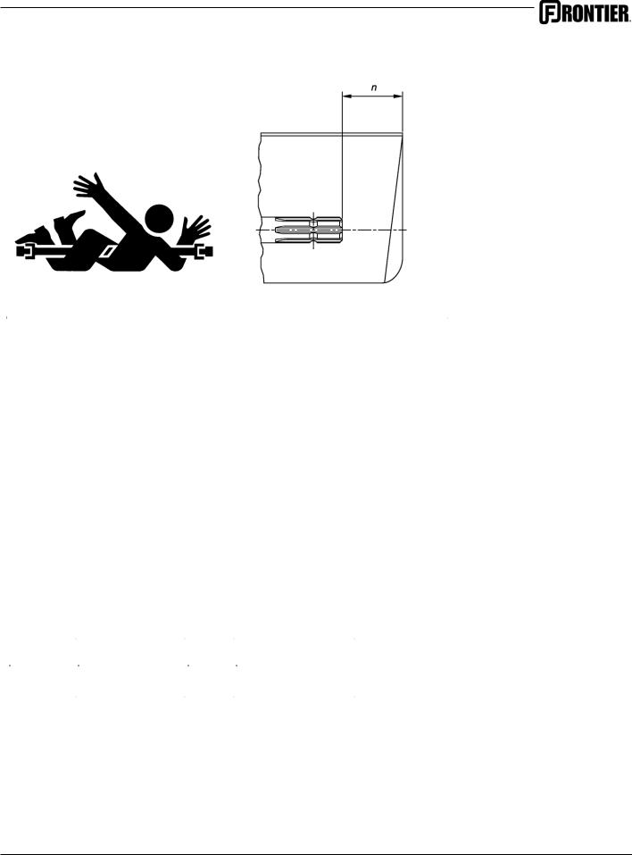
Stay Clear of Rotating Drivelines
TS1644-UN-22AUG95 |
H96219-UN-29APR10 |
|
|
Entanglement in rotating driveline can cause serious injury or death.
Keep tractor master shield and driveline shields in place at all times. Make sure rotating shields turn freely.
Wear close fitting clothing. Stop the engine and be sure that PTO driveline is stopped before making adjustments, connections, or cleaning out PTO driven equipment.
Do not install any adapter device between the tractor and the primary implement PTO drive shaft that will allow a 1000 rpm tractor shaft to power a 540 rpm implement at speeds higher than 540 rpm.
Do not install any adapter device that results in a portion of the rotating implement shaft, tractor shaft, or the adapter to be unguarded. The tractor master shield shall overlap the end of the splined shaft and the added adaptor device as outlined in the table.
|
|
|
|
|
|
|
PTO Type |
|
Diameter |
|
Splines |
|
n ± 5 mm (0.20 in.) |
|
|
|
|
|
|
|
1 |
|
35 mm (1.378 in.) |
|
6 |
|
85 mm (3.35 in.) |
|
|
|
|
|
|
|
|
|
|
|
|
|
|
2 |
|
35 mm (1.378 in.) |
|
21 |
|
85 mm (3.35 in.) |
|
|
|
|
|
|
|
3 |
|
45 mm (1.772 in.) |
|
20 |
|
100 mm (4.00 in.) |
|
|
|
|
|
|
|
|
|
|
|
|
|
|
5
DEALER SETUP
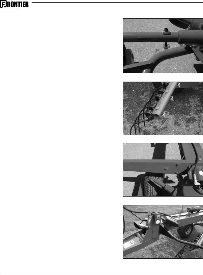
Tine Arms
Remove the rubber cap from the gearbox shaft. Slide the tine arm onto the shaft. Line up the hole and insert the M10 metric socket head bolt. Place one of the cupped washers on either side of the tine arm and tighten the locknut. Repeat for all 9 arms.
Tines
Attach three tines to each arm using the 1/2 x 3-1/4 Grade 8 bolts. Insert bolt from the top and clamp the tine in place with the 1/2” heavy washer and locknut.
Torque to 60-65 ft.-lbs.
Guard Support Arms
Attach the guard support arms to both sides of the rake using the 1/2” bolts. NOTE: The guard arm with the curtain mount tube is for the left side of the rake.
Guards, Front
Attach the front half of the guard to the main frame using the 3/8 x 1 bolts, lockwashers & nuts. Repeat both sides.
6
DEALER SETUP CONT’D
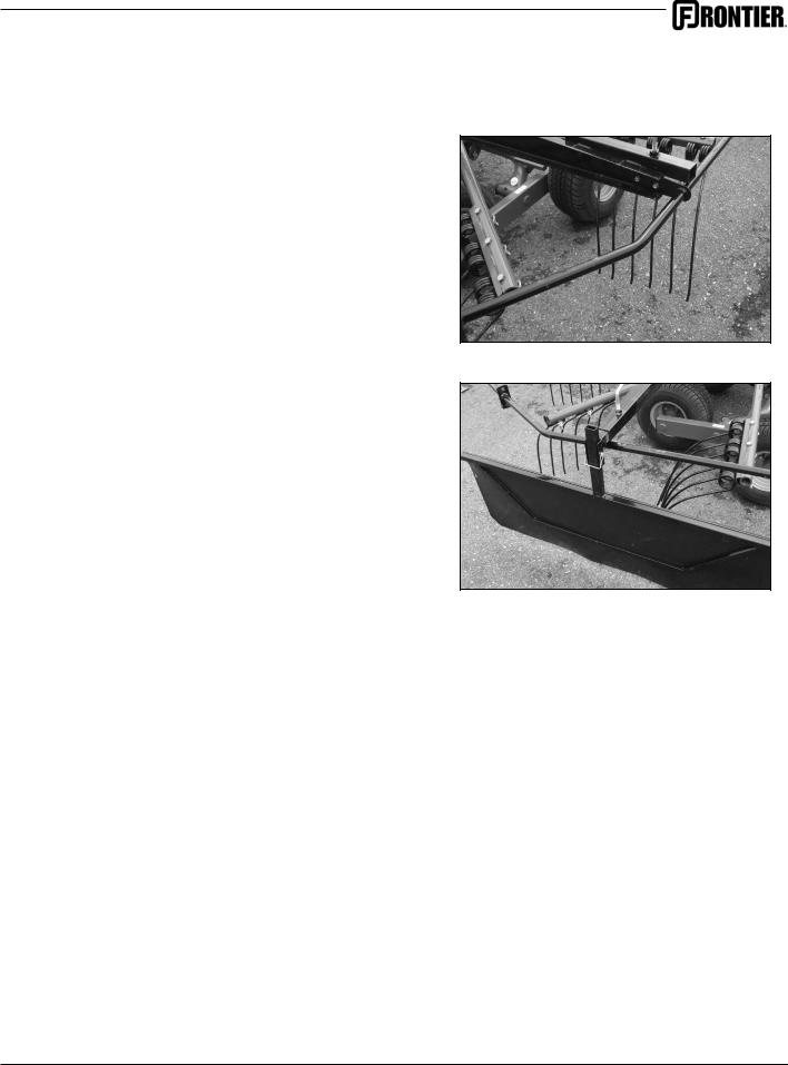
Guards, Rear
Attach the rear half of the guard to the guard support arm using the 5/16 bolts, lockwashers & nuts. Also attach to the front guard using 3/8 hardware.
Hay Curtain
Slide the curtain mount tube into the tube on the guard arm and lock with the locking handle. Attach the curtain and select the desired height. Insert locking pin to secure.
Note to customer: This setup for the RR2109 is usually done by the dealer, however, the arms and guards can easily be removed for winter storage if you prefer.
7
HITCHING
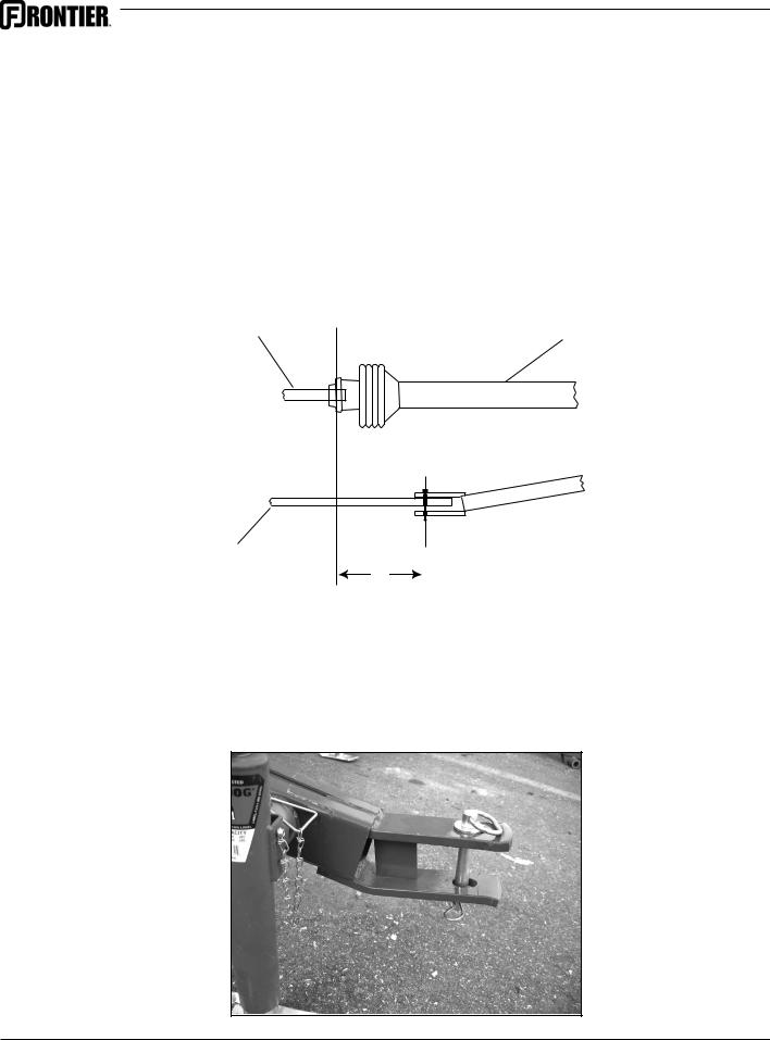
Tractor Requirements
The Frontier Rotary Rake is designed to be used with a tractor having a 540 RPM PTO. The hitch pin hole on the tractor should be 14” (35cm) from the rear of the groove in the PTO output shaft. (See illustration below)
NOTE: If the hitch pin hole is located well behind the tractor tires there is the potential of making a sharp enough turn to damage the rake PTO shaft.
Tractor PTO |
|
Shaft |
Rake Driveline |
Tractor Drawbar |
|
Center Line of Hitch |
|
||
|
14” |
Pin Hole |
|
|
|
|
|
|
Hitching
Align the hole in the tractor draw bar with the hole in the rake tongue and insert an approved hitch pin. Lock hitch pin with a safety clip to insure that it cannot work its way out. Attach the safety chain to the tractor.
8
 Loading...