


 Loading...
iGrade™
*OMPFP13592* |
OPERATOR'S MANUAL |
|
|
|
iGrade™ |
|
OMPFP13592 ISSUE C4 (ENGLISH) |
CALIFORNIA
Proposition 65 Warning
Diesel engine exhaust and some of its constituents are known to the State of California to cause cancer, birth defects, and other reproductive harm.
If this product contains a gasoline engine:
 WARNING
The engine exhaust from this product contains chemicals known to the State of California to cause cancer, birth defects or other reproductive harm.
The State of California requires the above two warnings.
Additional Proposition 65 Warnings can be found in this manual.
John Deere Ag Management Solutions
PRINTED IN U.S.A.
*DCY*
*OMPFP13592*

Introduction
www.StellarSupport.com
NOTE: Product functionality may not be fully represented in this document due to product changes occurring after the time of printing. Read the latest Operator's Manual and Quick Reference Guide prior to operation. To obtain a copy, see your dealer or visit www.StellarSupport.com
OUO6050,0000FB1 -19-10AUG10-1/1
Foreword
WELCOME to the iGrade™ System offered by John Deere.
READ THIS MANUAL carefully to learn how to operate and service your system correctly. Failure to do so could result in personal injury or equipment damage. This manual and safety signs on your machine may also be available in other languages. (See your John Deere dealer to order.)
THIS MANUAL SHOULD BE CONSIDERED a permanent part of your system and should remain with the system when you sell it.
MEASUREMENTS in this manual are given in both metric and customary U.S. unit equivalents. Use only correct replacement parts and fasteners. Metric and inch fasteners may require a specific metric or inch wrench.
RIGHT-HAND AND LEFT-HAND sides are determined by facing in the direction of forward travel.
WRITE PRODUCT IDENTIFICATION NUMBERS (P.I.N.) in the Specification or Identification Numbers section.
iGrade is a trademark of Deere & Company
Accurately record all the numbers to help in tracing the components should it be stolen. Your dealer also needs these numbers when you order parts. File the identification numbers in a secure place off the machine.
WARRANTY is provided as part of John Deere's support program for customers who operate and maintain their equipment as described in this manual. The warranty is explained on the warranty certificate which you should have received from your dealer.
This warranty provides you the assurance that John Deere will back its products where defects appear within the warranty period. In some circumstances, John Deere also provides field improvements, often without charge to the customer, even if the product is out of warranty. Should the equipment be abused, or modified to change its performance beyond the original factory specifications, the warranty will become void and field improvements may be denied.
RW00482,0000266 -19-19FEB14-1/1
031214
PN=2

Contents
|
Page |
Safety |
|
Recognize Safety Information ............................ |
05-1 |
Understand Signal Words................................... |
05-1 |
Follow Safety Instructions................................... |
05-1 |
Practice Safe Maintenance................................. |
05-2 |
Use Steps and Handholds Correctly .................. |
05-2 |
Handle Electronic Components and |
|
Brackets Safely .............................................. |
05-3 |
Operate Implement Automation |
|
Systems Safely .............................................. |
05-3 |
Avoid High-Pressure Fluids................................ |
05-4 |
Introduction |
|
Theory of Operation............................................ |
10-1 |
Activate iGrade™ ............................................... |
10-1 |
iGrade™ Requirements...................................... |
10-2 |
Machine Controller Compatibility........................ |
10-3 |
System Components |
|
iGrade™ Components........................................ |
15-1 |
SCV Setup |
|
Configure SCVs On CommandCen- |
|
ter™ - Auto Mode........................................... |
20-1 |
SCV Operation ................................................... |
20-2 |
Adjust Valve........................................................ |
20-3 |
Calibrate SCV Thresholds.................................. |
20-3 |
Basic Operation |
|
Basic Operation.................................................. |
25-1 |
Engage iGrade™................................................ |
25-2 |
Dual Scrapers..................................................... |
25-3 |
Load Limiting ...................................................... |
25-4 |
Max Cut .............................................................. |
25-5 |
Offsets ................................................................ |
25-6 |
Remote Control—Surface Water Pro™ Plus |
|
Theory of Operation............................................ |
30-1 |
Control Selection ................................................ |
30-1 |
Operation............................................................ |
30-2 |
Remote Control—Serial Port |
|
Theory of Operation............................................ |
35-1 |
Message Definition............................................. |
35-1 |
Serial Port Hardware .......................................... |
35-1 |
Serial Port Setup ................................................ |
35-2 |
Control Selection ................................................ |
35-3 |
|
Page |
Operation............................................................ |
35-3 |
Grade Control
Theory of Operation............................................ |
40-1 |
Grade Calculator ................................................ |
40-1 |
Selecting Grade.................................................. |
40-2 |
Plane Control
Theory of Operation............................................ |
45-1 |
Control Selection ................................................ |
45-2 |
Select Active Plane............................................. |
45-2 |
Single Slope Plane ............................................. |
45-3 |
Dual Slope Plane................................................ |
45-4 |
Plane Calculator ................................................. |
45-5 |
Dual Scraper....................................................... |
45-5 |
Operation............................................................ |
45-6 |
Distance Trip
Theory of Operation............................................ |
50-1 |
Select Distance Trip ........................................... |
50-1 |
Distance Trip Setup ............................................ |
50-2 |
Initiating Trip Cycle ............................................. |
50-3 |
Adjusting Trip Cycle............................................ |
50-3 |
Disconnecting iGrade™
Disconnect iGrade™ System ............................. |
55-1 |
Troubleshooting
Troubleshooting — iGrade™ System................. |
60-1 |
Troubleshooting — I/O Voltages Page ............... |
60-2 |
Troubleshooting — Machine............................... |
60-3 |
Maintenance
iGrade System.................................................... |
65-1 |
Preseason Checklist........................................... |
65-1 |
Daily Checklist.................................................... |
65-1 |
Postseason Checklist ......................................... |
65-2 |
Specifications
EC Declaration of Conformity............................. |
70-1 |
Original Instructions. All information, illustrations and specifications in this manual are based on the latest information available at the time of publication. The right is reserved to make changes at any time without notice.
COPYRIGHT © 2014
DEERE & COMPANY
Moline, Illinois
All rights reserved.
A John Deere ILLUSTRUCTION ® Manual
i
031214
PN=1

Contents
ii
031214
PN=2
Safety
Recognize Safety Information
This is a safety-alert symbol. When you see this symbol on your machine or in this manual, be alert to the potential for personal injury.
Follow recommended precautions and safe operating practices.
Understand Signal Words
A signal word—DANGER, WARNING, or CAUTION—is used with the safety-alert symbol. DANGER identifies the most serious hazards.
DANGER or WARNING safety signs are located near specific hazards. General precautions are listed on CAUTION safety signs. CAUTION also calls attention to safety messages in this manual.
T81389 —UN—28JUN13
DX,ALERT -19-29SEP98-1/1
TS187 —19—30SEP88
DX,SIGNAL -19-03MAR93-1/1
Follow Safety Instructions
Carefully read all safety messages in this manual and on your machine safety signs. Keep safety signs in good condition. Replace missing or damaged safety signs. Be sure new equipment components and repair parts include the current safety signs. Replacement safety signs are available from your John Deere dealer.
There can be additional safety information contained on parts and components sourced from suppliers that is not reproduced in this operator's manual.
Learn how to operate the machine and how to use controls properly. Do not let anyone operate without instruction.
Keep your machine in proper working condition. Unauthorized modifications to the machine may impair the function and/or safety and affect machine life.
TS201 —UN—15APR13
If you do not understand any part of this manual and need assistance, contact your John Deere dealer.
DX,READ -19-16JUN09-1/1
05-1 |
PN=5 |
|
031214 |
Safety
Practice Safe Maintenance |
|
Understand service procedure before doing work. Keep |
|
area clean and dry. |
|
Never lubricate, service, or adjust machine while it is |
|
moving. Keep hands, feet , and clothing from power-driven |
|
parts. Disengage all power and operate controls to relieve |
|
pressure. Lower equipment to the ground. Stop the |
|
engine. Remove the key. Allow machine to cool. |
|
Securely support any machine elements that must be |
|
raised for service work. |
|
Keep all parts in good condition and properly installed. |
|
Fix damage immediately. Replace worn or broken parts. |
|
Remove any buildup of grease, oil, or debris. |
|
On self-propelled equipment, disconnect battery ground |
|
cable (-) before making adjustments on electrical systems |
|
or welding on machine. |
|
On towed implements, disconnect wiring harnesses from |
|
tractor before servicing electrical system components or |
|
welding on machine. |
TS218 —UN—23AUG88 |
|
|
|
DX,SERV -19-17FEB99-1/1 |
|
|
|
|
Use Steps and Handholds Correctly |
|
Prevent falls by facing the machine when getting on and |
—UN—15APR13 |
off. Maintain 3-point contact with steps, handholds, and |
|
handrails. |
|
Use extra care when mud, snow, or moisture present |
|
slippery conditions. Keep steps clean and free of grease |
T133468 |
dismount a moving machine. |
|
or oil. Never jump when exiting machine. Never mount or |
|
|
DX,WW,MOUNT -19-12OCT11-1/1 |
|
|
05-2 |
PN=6 |
|
031214 |
Safety
Handle Electronic Components and Brackets
Safely
Falling while installing or removing electronic components mounted on equipment can cause serious injury. Use a ladder or platform to easily reach each mounting location. Use sturdy and secure footholds and handholds. Do not install or remove components in wet or icy conditions.
If installing or servicing a RTK base station on a tower or other tall structure, use a certified climber.
If installing or servicing a global positioning receiver mast used on an implement, use proper lifting techniques and wear proper protective equipment. The mast is heavy and can be awkward to handle. Two people are required when mounting locations are not accessible from the ground or from a service platform.
Operate Implement Automation Systems
Safely
Do not use implement automation systems on roadways. Always turn off (disable) implement automation systems before entering a roadway. Do not attempt to turn
on (activate) an implement automation system while transporting on a roadway.
Implement automation systems are intended to aid the operator in performing field operations more efficiently. The operator is always responsible for the machine path.
Implement automation systems include any application that automates implement movement. This includes, but may not be limited to, iGrade™ and Active Implement Guidance.
To prevent injury to the operator and bystanders:
•Verify the machine, implement, and automation systems are set up correctly.
•Remain alert and pay attention to the surrounding environment.
•Take control of the machine, when necessary, to avoid field hazards, bystanders, equipment, or other obstacles.
•Stop operation if poor visibility conditions impair your ability to operate the machine or identify people or obstacles in the machine path.
iGrade is a trademark of Deere & Company
TS249 —UN—23AUG88
DX,WW,RECEIVER -19-24AUG10-1/1
PC13793 —UN—25MAY11
CF86321,0000366 -19-19DEC13-1/1
05-3 |
PN=7 |
|
031214 |

Safety
Avoid High-Pressure Fluids
Inspect hydraulic hoses periodically – at least once per year – for leakage, kinking, cuts, cracks, abrasion,
blisters, corrosion, exposed wire braid or any other signs of wear or damage.
Replace worn or damaged hose assemblies immediately |
—UN—23AUG88 |
|
with John Deere approved replacement parts. |
|
|
Escaping fluid under pressure can penetrate the skin |
|
|
causing serious injury. |
X9811 |
|
Avoid the hazard by relieving pressure before |
||
|
||
disconnecting hydraulic or other lines. Tighten all |
|
|
connections before applying pressure. |
with this type of injury should reference a knowledgeable |
|
Search for leaks with a piece of cardboard. Protect hands |
||
medical source. Such information is available in |
||
and body from high-pressure fluids. |
English from Deere & Company Medical Department in |
|
If an accident occurs, see a doctor immediately. Any fluid |
Moline, Illinois, U.S.A., by calling 1-800-822-8262 or +1 |
|
309-748-5636. |
||
injected into the skin must be surgically removed within |
||
|
||
a few hours or gangrene may result. Doctors unfamiliar |
|
|
|
DX,FLUID -19-12OCT11-1/1 |
05-4 |
PN=8 |
|
031214 |
Introduction
Theory of Operation
iGrade™ is an active elevation control system which uses |
using distance trip to create irrigation bays for bedded |
|
selective control valves (SCVs) to control implement |
crop irrigation. |
|
height based off GPS elevation data. |
iGrade™ utilizes StarFire™ Receivers to obtain a |
|
iGrade™ has four functional modes: |
||
plane or elevation point correlated to a latitude and |
||
• Plane Control – used to create a surface design with |
longitude position. To function properly, setup is crucial to |
|
performance. Setup including but is not limited to: |
||
either a single slope direction or a dual slope direction. |
• SCV thresholds setup |
|
• Grade Control – performs desired slope entered based |
||
on actual distance traveled not linear distance. Grade |
• SCV flow rates setup |
|
control is not direction-dependent. |
• TCM calibrations setup |
|
• Remote Control – receives elevation data commands |
• Correctly setting a benchmark daily or a zero point for |
|
from an outside source to control implement height |
system reference |
|
through SCVs to a desired plane or ditch design. |
• Correct inputs into system for correct plane design |
|
• Distance Trip – allows GPS position to trigger machine |
|
|
hydraulics based on distance traveled. For example, |
|
|
iGrade is a trademark of Deere & Company |
|
|
StarFire is a trademark of Deere & Company |
|
|
|
RW00482,000025F -19-19FEB14-1/1 |
|
|
|
|
|
|
|
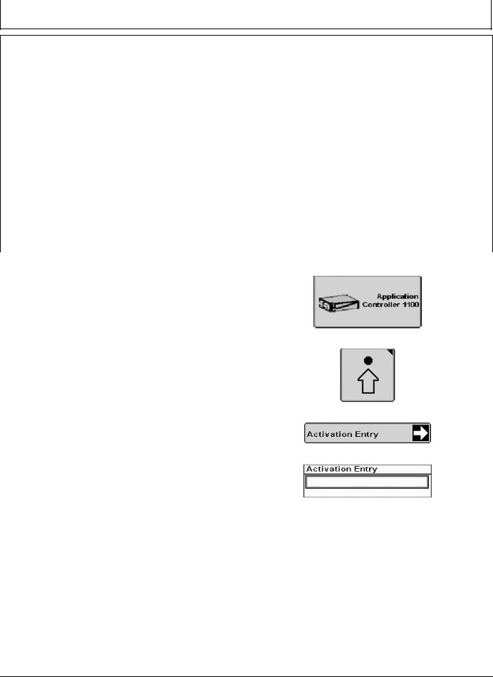
Activate iGrade™ |
PC14926 —UN—27APR12 |
|
|
||
To operate iGrade™, a 26-digit activation code is required |
|
|
for Application Controller 1100. |
|
|
1. Visit StellarSupport.com or call 1-888-953-3373. |
|
|
2. Use controller serial number and COMAR order |
Application Controller 1100 Button |
|
number to generate an activation code. |
PC12961 —UN—29AUG11 |
|
3. Select Application Controller 1100 from main menu. |
|
|
4. Select Setup softkey. |
|
|
5. Select Activation Entry button. |
|
|
6. Select activation input box and enter activation code. |
Setup Softkey |
|
If iGrade™ is activated, Activation Entry screen displays: |
PC17966 —UN—07NOV13 |
|
|
||
• Distance Trip |
|
|
• Remote Control |
Activation Entry Button |
|
• Grade Control |
||
PC17967 —UN—07NOV13 |
||
• Plane Control |
|
|
|
Activation Entry Box |
|
iGrade is a trademark of Deere & Company |
|
|
|
RW00482,0000225 -19-19FEB14-1/1 |
|
|
|
10-1 |
PN=9 |
|
031214 |

Introduction
iGrade™ Requirements
Display:
NOTE: Update software on display.
•GreenStar™ 2 2600 Display or GreenStar™ 3 2630 Display recommended.
•GreenStar™ 2 2100 Display and GreenStar™ 3 CommandCenter™ Display are compatible.
•Surface Water Pro™ Plus (SWP+) automation requires GS2 2600 Display or GS3 2630 Display.
Receiver:
•StarFire™ RTK Receivers installed and functioning on machine and implement.
•StarFire™ Receiver and Deluxe Bracket mounted on implement.
NOTE: A StarFire™ 300 Receiver can be used as a machine receiver to provide speed for Load Limiting application only.
•StarFire™ Receiver mounted on machine for Load Limiting, Max Cut, Distance Trip, AutoTrac™, and Surface Water Pro™ Plus automation (Remote Control).
•TCM turned on and calibrated.
•Machine receivers (Original StarFire™, StarFire™ iTC, or StarFire™ 3000) require RTK when using Distance Trip and Max Cut.
•Implement receivers (StarFire™ iTC or StarFire™ 3000) are required to have an RTK signal level.
NOTE: When operating dual scrapers, use same model of receiver on both implements. Only use two StarFire™ iTC Receivers or two StarFire™ 3000 Receivers. Receivers calculate elevation differently.
GreenStar is a trademark of Deere & Company Surface Water Pro is a trademark of Deere & Company AutoTrac is a trademark of Deere & Company StarFire is a trademark of Deere & Company
iGrade is a trademark of Deere & Company
When operating Surface Water Pro™, use same receivers (StarFire™ iTC or StarFire™ 3000) for collecting elevation data for ditching operation.
•Machine receivers can use SF1 or SF2 if Distance Trip is not being used and Max Cut is disabled.
•Receiver offsets can be entered for iGrade™. When using multiple implements, install receivers at same height from blade to receiver. If needed, adjust scraper offsets for application purposes.
•Implement receiver must not be mounted higher than 4 m (13.1 ft.) above ground level.
•Implement receiver must be connected to machine implement CAN Bus through ISO connector.
•Mount receiver mast on center line of implement over control point of implement.
•StarFire™ Global Navigation Satellite System (GNSS) antenna is recommended. Implement receivers may require use of StarFire™ GNSS antenna if operating iGrade™ in high multipath conditions. High multipath conditions can occur when satellites are low on horizon or signal reflects off a surface and intercepted by receiver.
Additional Hardware:
•Application Controller 1100 installed on machine.
•Various harnesses associated with power supply, controller integration, and receiver installation.
Optional:
•Complete AutoTrac™ setup and activate on display.
•Complete Surface Water setup if using Remote Control for SWP+ automation.
NOTE: iGrade™ does not use an implement feedback sensor.
RW00482,0000226 -19-11FEB14-1/1
10-2 |
PN=10 |
|
031214 |
Introduction
Machine Controller Compatibility |
Machine Controller Compatibility |
||
Machine Model |
Serial Numbers |
||
If installing iGrade™ on a machine in serial number |
|||
8100 |
-021245 |
||
ranges listed in table, contact a John Deere dealer to |
|||
|
|
||
8200 |
-021030 |
||
determine if any machine controllers require updates |
|||
|
|
||
8300 |
-021780 |
||
before operating iGrade™. |
|||
|
8400 |
-022341 |
|
|
|
|
|
|
8100T |
-902028 |
|
|
8200T |
-902047 |
|
|
8300T |
-902166 |
|
|
|
|
|
|
8400T |
-902636 |
|
|
|
|
|
|
9100 |
-10365 |
|
|
|
|
|
|
9200 |
-10849 |
|
|
|
|
|
|
9300 |
-10928 |
|
|
|
|
|
|
9400 |
-10931 |
|
|
|
|
|
iGrade is a trademark of Deere & Company
RW00482,0000261 -19-11FEB14-1/1
10-3 |
PN=11 |
|
031214 |
System Components
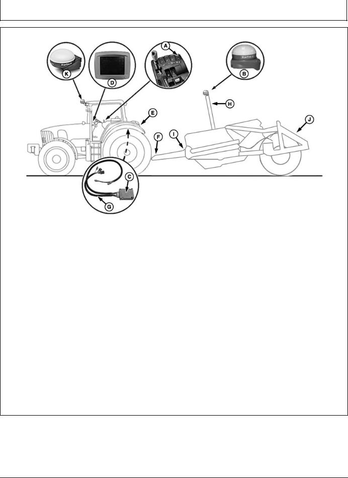
iGrade™ Components
PC18262 —UN—19DEC13
A—SCV Control Lever |
D—Display |
H—Implement Receiver |
K—StarFire™ RTK Receiver |
B—StarFire™ RTK Receiver with |
E—Constant Power Harness |
Application Harness |
|
Deluxe Shroud |
F—Front Extension Harness |
I— Center Extension Harness |
|
C—Application Controller |
G—Application Controller |
J— Rear Extension Harness |
|
|
Harness |
|
|
•Set SCV control lever (A) to AUTO or Actively Controlling (AC) mode.
•StarFire™ RTK Receiver (B) communicates elevation of blade height to application controller (C). Receivers require an RTK activation and radio installed for each implement receiver and for each machine receiver using Distance Trip and Max Cut.
•Application controller calculates desired elevation information from operator inputs entered in to display
(D).
•SCV controller receives instructions from application controller to automate blade height.
•Constant adjustments are made to keep height at targeted grade elevation.
•Constant power harness (E) connects to convenience outlet. Harness is routed to rear of cab where it connects to front extension harness (F) and application controller harnesses (G).
•Front extension harness is available in two different lengths 3 m (9.8 ft.) and 10 m (32.8 ft.). Harness
StarFire is a trademark of Deere & Company
connects to constant power harness and ISO implement connector. Harness is routed along frame of machine and connects to implement receiver application harness
(H).
•If needed, center extension harness (I) extends the distance between front extension harness and implement receiver application harness. Harness is
available in two lengths 2 m (6.6 ft.) and 8 m (26.2 ft.).
•Implement receiver application harness connects to front extension harness and is routed up mast to implement receiver.
NOTE: If a rear extension harness (J) is not used, a terminator is needed at end of harness.
•Rear extension harness (optional) provides ISO 9-pin connector on rear of scraper.
RW00482,0000228 -19-11FEB14-1/1
15-1 |
PN=12 |
|
031214 |

SCV Setup
Configure SCVs On CommandCenter™ - Auto Mode
RXA0117610 —UN—10JUN11
CommandARM™ Menu Button > SCV Softkey > Advanced Settings Softkey
PC18244 —UN—17DEC13
SCV Advanced Settings Page
|
PC18245 —UN—20DEC13 |
PC18246 —UN—19DEC13 |
SCV Home Page |
Auto Mode Indicators |
|
A—Independent Mode Checkbox |
D—Auto Status Indicator (Normal |
F—Auto Status Indicator (Turned I— Detent Time Drop-down Menu |
B—Detent Flow Bar Graph |
Operation) |
Off) |
C—Detent Flow Value Box |
E—Auto Status Indicator (Fault |
G—Extend Set Softkey |
|
Identified) |
H—Auto Mode Checkbox |
To use Auto mode, application controller must be installed and connected to machine. When connected through CAN Bus or implement connector, SCV(s) automatically enter feature mode. SCV Home page with feature option displays for selected SCVs. On Advanced Settings page, specified SCV independent mode checkbox (A) is grayed out.
1.Connect implement to machine.
2.Select Menu button.
3.Select SCV softkey.
4.Select Advanced Settings softkey.
NOTE: Bar graph (B) depicts detent flow. Amount of detent flow is shown in box (C).
AUTO (D) indicates normal auto mode operation. !AUTO! (E) indicates a fault and auto mode is
CommandARM is a trademark of Deere & Company
inoperable. AUTO with a strike through it (F) indicates auto mode is not active.
5.Select Extend Set softkey (G) to navigate to detent flow bar graph. Select Confirm button to highlight. Rotate thumb wheel to adjust flow, then select Confirm button.
NOTE: Detent time drop-down (H) can only be adjusted when auto mode checkbox (I) is unchecked.
If auto mode checkbox is checked, detent time cannot be adjusted. Use standard mode when adjusting detent time.
6.To adjust detent, rotate thumb wheel to auto mode checkbox to left of AUTO, then select Confirm button. When checkbox is unselected, AUTO displays with a strike through it.
RW00482,00001D4 -19-11FEB14-1/1
20-1 |
PN=13 |
|
031214 |
SCV Setup
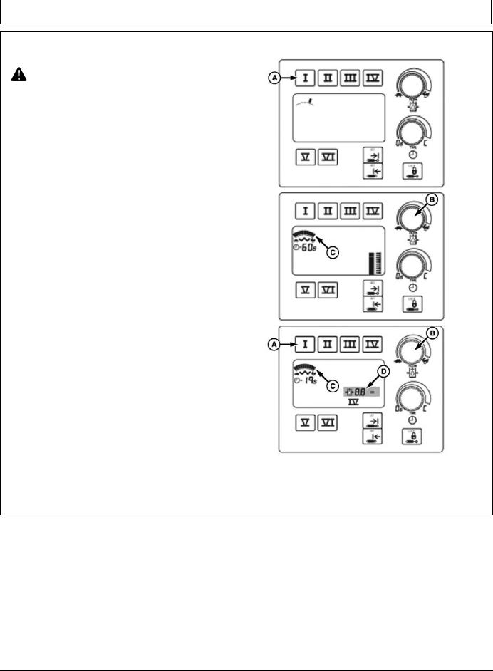
Adjust SCV Flow Rate
CAUTION: Excessive operating speed can cause damage or injury. Full extension or retraction of cylinder should take at least 2 seconds.
Adjust rate of operation for each job. Rate should be slow enough to be safe, yet fast enough to be practical.
Change flow setting as follows:
1.Press selected SCV switch (A). Display below touch switch shows previous rate of flow.
NOTE: To provide operator with additional indication of command setting, as operator “clicks” flow knob (B) through the flow settings, the display will increase or decrease the number of multiple line increments as the flow changes.
2.Turn flow rate knob clockwise (rabbit) to increase flow or counterclockwise (turtle) to decrease flow. Flow setting is shown on bar graph display (C) when adjustments are made.
NOTE: SCV can be operated to observe flow rate while in adjustment mode. Reduced cylinder cycle times and (or) a reduction in motor speed may result if total flow demand exceeds available pump flow.
SCV FLOW OUTPUT (APPROXIMATE) |
|
|
|
Flow |
|
SCV Flow Settings |
L/min. |
gpm |
0.1 a |
— |
— |
1.0 |
3.6 |
1.0 |
2.0 |
7.2 |
1.9 |
3.0 |
10.2 |
2.7 |
4.0 |
14.4 |
3.8 |
5.0 |
19.2 |
5.0 |
6.0 |
24.0 |
6.4 |
7.0 |
31.2 |
8.2 |
8.0 |
39.6 |
10.5 |
9.0 |
65.4 |
17.2 |
10.0 |
114 |
30.0 |
a 0.1 = Minimum Flow Setting
A—SCV Switch |
C—Bar Graph Display |
B—Flow Rate Knob |
D—Multiple Dashes |
PC18357 —UN—13JAN14
PC18358 —UN—13JAN14
PC18359 —UN—13JAN14
RW00482,0000267 -19-10FEB14-1/1
20-2 |
PN=14 |
|
031214 |
SCV Setup
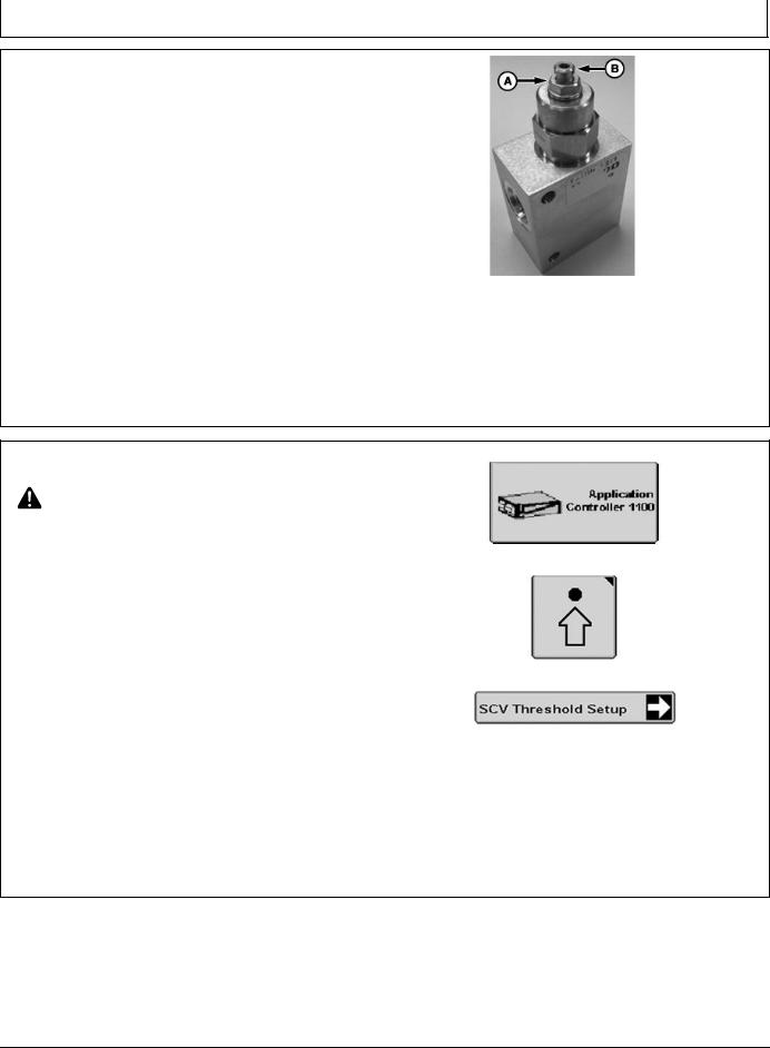
Adjust Valve
NOTE: Flow rates between 11–30 L/min. (3—8 gpm) are recommended.
If hydraulic flow rate is adjusted, complete
SCV threshold calibration test.
1. |
Adjust hydraulic flow on machine to operators |
|
|
|
preference, then adjust valve. |
|
|
2. |
Loosen lock nut (A) on valve cartridge. |
|
|
3. |
Use 1/4 turn increments to adjust valve. If implement is: |
|
|
|
• erratic or moves too fast, turn cartridge clockwise |
|
|
|
until implement reaches desired operation. |
|
|
|
• slow or not responsive, turn cartridge |
A—Lock Nut |
B—Valve Cartridge |
|
counterclockwise until implement reaches desired |
operation.
PC14814 —UN—29MAR12
NOTE: Torque lock nut to 20—25 N·m (15–18 lb.-ft.).
4. Tighten lock nut on valve cartridge.
If acceptable performance is not reached after adjusting valve, adjust hydraulic flow rate on machine then readjust valve.
RW00482,00001EB -19-09JAN14-1/1
Calibrate SCV Thresholds
CAUTION: To avoid serious injury, keep area around equipment clear. This procedure requires machine to move forward.
Implement will move during calibration.
PC14926 —UN—27APR12
Application Controller 1100 Button
PC12961 —UN—29AUG11
NOTE: Anytime an adjustment to system is made, such as SCV hydraulic flow rate or counterbalance valve adjustment, calibrate SCV threshold.
SCV threshold calibration is necessary for optimal performance. Perform SCV threshold calibration each time Application Controller with iGrade™ is installed on a different machine. Without SCV threshold calibration, scraper may move significantly faster in one direction, undercompensate, overcompensate, or not perform as expected due to hydraulic limitations.
To calibrate SCV, machine must move faster than 0.5 km/h (0.3 mph) to initiate hydraulic flow for SCV control. Select SCV (1 or 3) then AC mode as indicated on SCV control display. Implement does not need to be in working (lowered) position to calibrate.
1. Select Application Controller 1100 button.
iGrade is a trademark of Deere & Company
Setup Softkey
PC18039 —UN—11NOV13
SCV Threshold Setup Button
2.Select Setup softkey.
3.Select SCV Threshold Setup button.
Continued on next page |
RW00482,0000259 -19-06MAR14-1/2 |
20-3 |
PN=15 |
|
031214 |
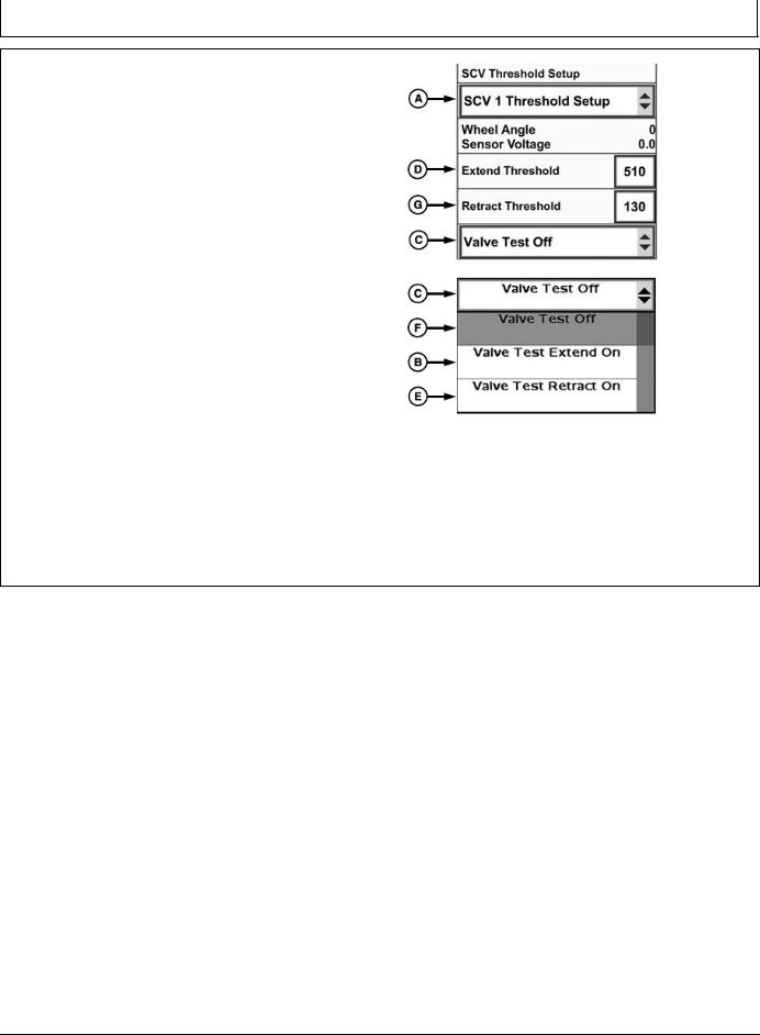
SCV Setup
4.Select SCV being used from SCV Threshold Setup drop-down (A).
5.Select Valve Test Extend On (B) from Valve Test drop-down menu (C).
6.Place SCV lever into detent.
NOTE: Extend raises implement and retract lowers implement.
7.Adjust Extend Threshold value (D) to lowest setting that produces a steady, consistent motion.
•If scraper height does not change, increase Extend Threshold value, until minimal movement is achieved.
•If scraper moves quickly or erratically, decrease Extend Threshold.
•Repeat procedure as required to obtain a smooth, constant change in scraper height.
•Extend and Retract thresholds valves may have different values.
8.Select Valve Test Retract On (E) from drop-down.
9.Repeat adjustment procedures used in Valve Test Extend calibration.
10.Turn Valve Test Off (F) when calibration is complete.
If SCV flow rate is too high, scraper could be overly sensitive and cause washboard effect.
If SCV flow rate is too low, control and load limit functionality could be impaired or limited.
|
PC18407 —UN—23JAN14 |
SCV Threshold Setup |
|
|
PC18248 —UN—17DEC13 |
Valve Test Drop-down Menu |
|
A—SCV Threshold Setup |
E—Valve Test Retract On |
Drop-down Menu |
F—Valve Test Off |
B—Valve Test Extend On |
G—Retract Threshold |
C—Valve Test Drop-down Menu |
|
D—Extend Threshold |
|
RW00482,0000259 -19-06MAR14-2/2
20-4 |
PN=16 |
|
031214 |
Loading...