

Page 1
Service and Maintenance Manual
Models
E450A
E450AJ
M450A
M450AJ
SN 0300208529
to Present
AS/NZS
PN - 3121714
November 30, 2018 - Rev D
Page 2

Page 3
SECTION A. INTRODUCTION - MAINTENANCE SAFETY PRECAUTIONS
INTRODUCTION
AGENERAL
This section contains the general safety precautions which
must be observed during maintenance of the aerial platform.
It is of utmost importance that maintenance personnel pay
strict attention to these warnings and precautions to avoid
possible injury to themselves or others, or damage to the
equipment. A maintenance program must be followed to
ensure that the machine is safe to operate.
MODIFICATION OR ALTERATION OF AN AERIAL WORK PLATFORM SHALL BE
MADE ONLY WITH WRITTEN PERMISSION FROM THE MANUFACTURER.
The specific precautions to be observed during maintenance
are inserted at the appropriate point in the manual. These precautions are, for the most part, those that apply when servicing hydraulic and larger machine component parts.
Your safety, and that of others, is the first consideration when
engaging in the maintenance of equipment. Always be conscious of weight. Never attempt to move heavy parts without
the aid of a mechanical device. Do not allow heavy objects to
rest in an unstable position. When raising a portion of the
equipment, ensure that adequate support is provided.
SINCE THE MACHINE MANUFACTURER HAS NO DIRECT CONTROL OVER THE
FIELD INSPECTION AND MAINTENANCE, SAFETY IN THIS AREA RESPONSIBILITY OF THE OWNER/OPERATOR.
BHYDRAULIC SYSTEM SAFETY
It should be noted that the machines hydraulic systems operate at extremely high potentially dangerous pressures. Every
effort should be made to relieve any system pressure prior to
disconnecting or removing any portion of the system.
Do not use your hand to check for leaks. Use a piece of cardboard or paper to search for leaks. Wear gloves to help protect
hands from spraying fluid.
CMAINTENANCE
FAILURE TO COMPLY WITH SAFETY PRECAUTIONS LISTED IN THIS SECTION
COULD RESULT IN MACHINE DAMAGE, PERSONNEL INJURY OR DEATH AND IS A
SAFETY VIOLATION.
• ENSURE REPLACEMENT PARTS OR COMPONENTS ARE
IDENTICAL OR EQUIVALENT TO ORIGINAL PARTS OR
COMPONENTS.
• NO SMOKING IS MANDATORY. NEVER REFUEL DURING ELECTRICAL STORMS. ENSURE THAT FUEL CAP IS CLOSED AND
SECURE AT ALL OTHER TIMES.
• REMOVE ALL RINGS, WATCHES AND JEWELRY WHEN PERFORMING ANY MAINTENANCE.
• DO NOT WEAR LONG HAIR UNRESTRAINED, OR LOOSE-FITTING CLOTHING AND NECKTIES WHICH ARE APT TO BECOME
CAUGHT ON OR ENTANGLED IN EQUIPMENT.
• OBSERVE AND OBEY ALL WARNINGS AND CAUTIONS ON
MACHINE AND IN SERVICE MANUAL.
• KEEP OIL, GREASE, WATER, ETC. WIPED FROM STANDING
SURFACES AND HAND HOLDS.
• USE CAUTION WHEN CHECKING A HOT, PRESSURIZED COOLANT SYSTEM.
• NEVER WORK UNDER AN ELEVATED BOOM UNTIL BOOM HAS
BEEN SAFELY RESTRAINED FROM ANY MOVEMENT BY
BLOCKING OR OVERHEAD SLING, OR BOOM SAFETY PROP
HAS BEEN ENGAGED.
• BEFORE MAKING ADJUSTMENTS, LUBRICATING OR PERFORMING ANY OTHER MAINTENANCE, SHUT OFF ALL
POWER CONTROLS.
• BATTERY SHOULD ALWAYS BE DISCONNECTEDDURING
REPLACEMENT OF ELECTRICAL COMPONENTS.
• KEEP ALL SUPPORT EQUIPMENT AND ATTACHMENTS
STOWED IN THEIR PROPER PLACE.
• USE ONLY APPROVED, NONFLAMMABLE CLEANING SOLVENTS.
3121714 A-1
Page 4

INTRODUCTION
REVISON LOG
Original Issue A - October 31, 2016
Revised B - August 23, 2017
Revised C - June 29, 2018 - Revised Covers
Revised D - November 30, 2018
A-2 3121714
Page 5

TABLE OF CONTENTS
SECTION NO. TITLE PAGE NO.
SECTION A - INTRODUCTION - MAINTENANCE SAFETY PRECAUTIONS
A General . . . . . . . . . . . . . . . . . . . . . . . . . . . . . . . . . . . . . . . . . . . . . . . . . . . . . . . . . . . . . . . . . . . . . . . . . . . . . . . . . . . . . . . . . . . . A-1
B Hydraulic System Safety . . . . . . . . . . . . . . . . . . . . . . . . . . . . . . . . . . . . . . . . . . . . . . . . . . . . . . . . . . . . . . . . . . . . . . . . . . . . A-1
C Maintenance. . . . . . . . . . . . . . . . . . . . . . . . . . . . . . . . . . . . . . . . . . . . . . . . . . . . . . . . . . . . . . . . . . . . . . . . . . . . . . . . . . . . . . . A-1
SECTION 1 - SPECIFICATIONS
1.1 Operating Specifications . . . . . . . . . . . . . . . . . . . . . . . . . . . . . . . . . . . . . . . . . . . . . . . . . . . . . . . . . . . . . . . . . . . . . . . . . . . 1-1
1.2 Tires . . . . . . . . . . . . . . . . . . . . . . . . . . . . . . . . . . . . . . . . . . . . . . . . . . . . . . . . . . . . . . . . . . . . . . . . . . . . . . . . . . . . . . . . . . . . . . . 1-1
1.3 Capacities . . . . . . . . . . . . . . . . . . . . . . . . . . . . . . . . . . . . . . . . . . . . . . . . . . . . . . . . . . . . . . . . . . . . . . . . . . . . . . . . . . . . . . . . . 1-1
1.4 Dimensional Data . . . . . . . . . . . . . . . . . . . . . . . . . . . . . . . . . . . . . . . . . . . . . . . . . . . . . . . . . . . . . . . . . . . . . . . . . . . . . . . . . . 1-2
1.5 Torque Specifications . . . . . . . . . . . . . . . . . . . . . . . . . . . . . . . . . . . . . . . . . . . . . . . . . . . . . . . . . . . . . . . . . . . . . . . . . . . . . . 1-2
1.6 Lubrication Specifications . . . . . . . . . . . . . . . . . . . . . . . . . . . . . . . . . . . . . . . . . . . . . . . . . . . . . . . . . . . . . . . . . . . . . . . . . . 1-2
Hydraulic Oil . . . . . . . . . . . . . . . . . . . . . . . . . . . . . . . . . . . . . . . . . . . . . . . . . . . . . . . . . . . . . . . . . . . . . . . . . . . . . . . . . . 1-2
1.7 Critical Stability Weights. . . . . . . . . . . . . . . . . . . . . . . . . . . . . . . . . . . . . . . . . . . . . . . . . . . . . . . . . . . . . . . . . . . . . . . . . . . . 1-3
1.8 Major Component Weights. . . . . . . . . . . . . . . . . . . . . . . . . . . . . . . . . . . . . . . . . . . . . . . . . . . . . . . . . . . . . . . . . . . . . . . . . 1-3
1.9 Serial Number Locations . . . . . . . . . . . . . . . . . . . . . . . . . . . . . . . . . . . . . . . . . . . . . . . . . . . . . . . . . . . . . . . . . . . . . . . . . . . 1-3
1.10 Maintenance and Lubrication . . . . . . . . . . . . . . . . . . . . . . . . . . . . . . . . . . . . . . . . . . . . . . . . . . . . . . . . . . . . . . . . . . . . . . 1-5
SECTION 2 - GENERAL
2.1 Machine Preparation, Inspection, and Maintenance . . . . . . . . . . . . . . . . . . . . . . . . . . . . . . . . . . . . . . . . . . . . . . . . . 2-1
General . . . . . . . . . . . . . . . . . . . . . . . . . . . . . . . . . . . . . . . . . . . . . . . . . . . . . . . . . . . . . . . . . . . . . . . . . . . . . . . . . . . . . . . 2-1
Preparation, Inspection, and Maintenance . . . . . . . . . . . . . . . . . . . . . . . . . . . . . . . . . . . . . . . . . . . . . . . . . . . . . 2-1
Pre-Start Inspection . . . . . . . . . . . . . . . . . . . . . . . . . . . . . . . . . . . . . . . . . . . . . . . . . . . . . . . . . . . . . . . . . . . . . . . . . . . 2-1
Pre-Delivery Inspection and Frequent Inspection. . . . . . . . . . . . . . . . . . . . . . . . . . . . . . . . . . . . . . . . . . . . . . . 2-1
Annual Machine Inspection. . . . . . . . . . . . . . . . . . . . . . . . . . . . . . . . . . . . . . . . . . . . . . . . . . . . . . . . . . . . . . . . . . . . 2-1
Preventative Maintenance. . . . . . . . . . . . . . . . . . . . . . . . . . . . . . . . . . . . . . . . . . . . . . . . . . . . . . . . . . . . . . . . . . . . . 2-1
2.2 Service and Guidelines . . . . . . . . . . . . . . . . . . . . . . . . . . . . . . . . . . . . . . . . . . . . . . . . . . . . . . . . . . . . . . . . . . . . . . . . . . . . . 2-2
General . . . . . . . . . . . . . . . . . . . . . . . . . . . . . . . . . . . . . . . . . . . . . . . . . . . . . . . . . . . . . . . . . . . . . . . . . . . . . . . . . . . . . . . 2-2
Safety and Workmanship . . . . . . . . . . . . . . . . . . . . . . . . . . . . . . . . . . . . . . . . . . . . . . . . . . . . . . . . . . . . . . . . . . . . . . 2-2
Cleanliness. . . . . . . . . . . . . . . . . . . . . . . . . . . . . . . . . . . . . . . . . . . . . . . . . . . . . . . . . . . . . . . . . . . . . . . . . . . . . . . . . . . . 2-2
Components Removal and Installation. . . . . . . . . . . . . . . . . . . . . . . . . . . . . . . . . . . . . . . . . . . . . . . . . . . . . . . . . 2-2
Component Disassembly and Reassembly . . . . . . . . . . . . . . . . . . . . . . . . . . . . . . . . . . . . . . . . . . . . . . . . . . . . . 2-3
Pressure-Fit Parts. . . . . . . . . . . . . . . . . . . . . . . . . . . . . . . . . . . . . . . . . . . . . . . . . . . . . . . . . . . . . . . . . . . . . . . . . . . . . . 2-3
Bearings . . . . . . . . . . . . . . . . . . . . . . . . . . . . . . . . . . . . . . . . . . . . . . . . . . . . . . . . . . . . . . . . . . . . . . . . . . . . . . . . . . . . . . 2-3
Gaskets . . . . . . . . . . . . . . . . . . . . . . . . . . . . . . . . . . . . . . . . . . . . . . . . . . . . . . . . . . . . . . . . . . . . . . . . . . . . . . . . . . . . . . . 2-3
Bolt Usage and Torque Application . . . . . . . . . . . . . . . . . . . . . . . . . . . . . . . . . . . . . . . . . . . . . . . . . . . . . . . . . . . . 2-3
Hydraulic Lines and Electrical Wiring. . . . . . . . . . . . . . . . . . . . . . . . . . . . . . . . . . . . . . . . . . . . . . . . . . . . . . . . . . . 2-3
Hydraulic System. . . . . . . . . . . . . . . . . . . . . . . . . . . . . . . . . . . . . . . . . . . . . . . . . . . . . . . . . . . . . . . . . . . . . . . . . . . . . . 2-3
Lubrication . . . . . . . . . . . . . . . . . . . . . . . . . . . . . . . . . . . . . . . . . . . . . . . . . . . . . . . . . . . . . . . . . . . . . . . . . . . . . . . . . . . 2-4
Battery. . . . . . . . . . . . . . . . . . . . . . . . . . . . . . . . . . . . . . . . . . . . . . . . . . . . . . . . . . . . . . . . . . . . . . . . . . . . . . . . . . . . . . . . 2-4
Lubrication and Servicing . . . . . . . . . . . . . . . . . . . . . . . . . . . . . . . . . . . . . . . . . . . . . . . . . . . . . . . . . . . . . . . . . . . . . 2-4
2.3 Lubrication and Information. . . . . . . . . . . . . . . . . . . . . . . . . . . . . . . . . . . . . . . . . . . . . . . . . . . . . . . . . . . . . . . . . . . . . . . . 2-4
Hydraulic System. . . . . . . . . . . . . . . . . . . . . . . . . . . . . . . . . . . . . . . . . . . . . . . . . . . . . . . . . . . . . . . . . . . . . . . . . . . . . . 2-4
Hydraulic Oil . . . . . . . . . . . . . . . . . . . . . . . . . . . . . . . . . . . . . . . . . . . . . . . . . . . . . . . . . . . . . . . . . . . . . . . . . . . . . . . . . . 2-4
Changing Hydraulic Oil. . . . . . . . . . . . . . . . . . . . . . . . . . . . . . . . . . . . . . . . . . . . . . . . . . . . . . . . . . . . . . . . . . . . . . . . 2-4
Lubrication Specifications . . . . . . . . . . . . . . . . . . . . . . . . . . . . . . . . . . . . . . . . . . . . . . . . . . . . . . . . . . . . . . . . . . . . . 2-4
2.4 Cylinder Drift . . . . . . . . . . . . . . . . . . . . . . . . . . . . . . . . . . . . . . . . . . . . . . . . . . . . . . . . . . . . . . . . . . . . . . . . . . . . . . . . . . . . . . 2-5
Theory . . . . . . . . . . . . . . . . . . . . . . . . . . . . . . . . . . . . . . . . . . . . . . . . . . . . . . . . . . . . . . . . . . . . . . . . . . . . . . . . . . . . . . . . 2-5
Cylinder Leakage Test . . . . . . . . . . . . . . . . . . . . . . . . . . . . . . . . . . . . . . . . . . . . . . . . . . . . . . . . . . . . . . . . . . . . . . . . . 2-5
Cylinder Thermal Drift . . . . . . . . . . . . . . . . . . . . . . . . . . . . . . . . . . . . . . . . . . . . . . . . . . . . . . . . . . . . . . . . . . . . . . . . . 2-5
2.5 Pins and Composite Bearing Repair Guidelines . . . . . . . . . . . . . . . . . . . . . . . . . . . . . . . . . . . . . . . . . . . . . . . . . . . . . . 2-6
2.6 Welding on JLG Equipment. . . . . . . . . . . . . . . . . . . . . . . . . . . . . . . . . . . . . . . . . . . . . . . . . . . . . . . . . . . . . . . . . . . . . . . . . 2-6
Do the Following When Welding on JLG Equipment. . . . . . . . . . . . . . . . . . . . . . . . . . . . . . . . . . . . . . . . . . . . 2-6
Do NOT Do the Following When Welding on JLG Equipment . . . . . . . . . . . . . . . . . . . . . . . . . . . . . . . . . . . 2-6
3121714 i
Page 6

TABLE OF CONTENTS
SECTION NO. TITLE PAGE NO.
SECTION 3 - CHASSIS & TURNTABLE
3.1 Tires & Wheels. . . . . . . . . . . . . . . . . . . . . . . . . . . . . . . . . . . . . . . . . . . . . . . . . . . . . . . . . . . . . . . . . . . . . . . . . . . . . . . . . . . . . . 3-1
Tire Inflation. . . . . . . . . . . . . . . . . . . . . . . . . . . . . . . . . . . . . . . . . . . . . . . . . . . . . . . . . . . . . . . . . . . . . . . . . . . . . . . . . . 3-1
Tire Damage . . . . . . . . . . . . . . . . . . . . . . . . . . . . . . . . . . . . . . . . . . . . . . . . . . . . . . . . . . . . . . . . . . . . . . . . . . . . . . . . . 3-1
Tire Replacement. . . . . . . . . . . . . . . . . . . . . . . . . . . . . . . . . . . . . . . . . . . . . . . . . . . . . . . . . . . . . . . . . . . . . . . . . . . . . 3-1
Wheel Replacement . . . . . . . . . . . . . . . . . . . . . . . . . . . . . . . . . . . . . . . . . . . . . . . . . . . . . . . . . . . . . . . . . . . . . . . . . . 3-1
Wheel Installation . . . . . . . . . . . . . . . . . . . . . . . . . . . . . . . . . . . . . . . . . . . . . . . . . . . . . . . . . . . . . . . . . . . . . . . . . . . . 3-1
3.2 Spindle . . . . . . . . . . . . . . . . . . . . . . . . . . . . . . . . . . . . . . . . . . . . . . . . . . . . . . . . . . . . . . . . . . . . . . . . . . . . . . . . . . . . . . . . . . . . 3-2
Setting Wheel Bearing End Play . . . . . . . . . . . . . . . . . . . . . . . . . . . . . . . . . . . . . . . . . . . . . . . . . . . . . . . . . . . . . . . 3-2
Specifications . . . . . . . . . . . . . . . . . . . . . . . . . . . . . . . . . . . . . . . . . . . . . . . . . . . . . . . . . . . . . . . . . . . . . . . . . . . . . . . . 3-2
Checking. . . . . . . . . . . . . . . . . . . . . . . . . . . . . . . . . . . . . . . . . . . . . . . . . . . . . . . . . . . . . . . . . . . . . . . . . . . . . . . . . . . . . 3-2
Greasing Requirements . . . . . . . . . . . . . . . . . . . . . . . . . . . . . . . . . . . . . . . . . . . . . . . . . . . . . . . . . . . . . . . . . . . . . . . 3-2
3.3 Tilt Module. . . . . . . . . . . . . . . . . . . . . . . . . . . . . . . . . . . . . . . . . . . . . . . . . . . . . . . . . . . . . . . . . . . . . . . . . . . . . . . . . . . . . . . . . 3-5
3.4 Speed Sensor . . . . . . . . . . . . . . . . . . . . . . . . . . . . . . . . . . . . . . . . . . . . . . . . . . . . . . . . . . . . . . . . . . . . . . . . . . . . . . . . . . . . . . 3-6
3.5 Drive Hub . . . . . . . . . . . . . . . . . . . . . . . . . . . . . . . . . . . . . . . . . . . . . . . . . . . . . . . . . . . . . . . . . . . . . . . . . . . . . . . . . . . . . . . . . . 3-13
Roll and Leak Testing . . . . . . . . . . . . . . . . . . . . . . . . . . . . . . . . . . . . . . . . . . . . . . . . . . . . . . . . . . . . . . . . . . . . . . . . . 3-13
Tightening and Torquing Bolts. . . . . . . . . . . . . . . . . . . . . . . . . . . . . . . . . . . . . . . . . . . . . . . . . . . . . . . . . . . . . . . . 3-13
Main Disassembly . . . . . . . . . . . . . . . . . . . . . . . . . . . . . . . . . . . . . . . . . . . . . . . . . . . . . . . . . . . . . . . . . . . . . . . . . . . . 3-14
Output Carrier Disassembly . . . . . . . . . . . . . . . . . . . . . . . . . . . . . . . . . . . . . . . . . . . . . . . . . . . . . . . . . . . . . . . . . . . 3-16
Input Carrier Disassembly. . . . . . . . . . . . . . . . . . . . . . . . . . . . . . . . . . . . . . . . . . . . . . . . . . . . . . . . . . . . . . . . . . . . . 3-18
Hub-spindle Disassembly . . . . . . . . . . . . . . . . . . . . . . . . . . . . . . . . . . . . . . . . . . . . . . . . . . . . . . . . . . . . . . . . . . . . . 3-19
Cover Disassembly . . . . . . . . . . . . . . . . . . . . . . . . . . . . . . . . . . . . . . . . . . . . . . . . . . . . . . . . . . . . . . . . . . . . . . . . . . . 3-20
Input Carrier Assembly . . . . . . . . . . . . . . . . . . . . . . . . . . . . . . . . . . . . . . . . . . . . . . . . . . . . . . . . . . . . . . . . . . . . . . . 3-21
Output Planet Gear Assembly. . . . . . . . . . . . . . . . . . . . . . . . . . . . . . . . . . . . . . . . . . . . . . . . . . . . . . . . . . . . . . . . . 3-21
Output Carrier Assembly. . . . . . . . . . . . . . . . . . . . . . . . . . . . . . . . . . . . . . . . . . . . . . . . . . . . . . . . . . . . . . . . . . . . . . 3-22
Hub-spindle Assembly. . . . . . . . . . . . . . . . . . . . . . . . . . . . . . . . . . . . . . . . . . . . . . . . . . . . . . . . . . . . . . . . . . . . . . . . 3-22
Cover Assembly . . . . . . . . . . . . . . . . . . . . . . . . . . . . . . . . . . . . . . . . . . . . . . . . . . . . . . . . . . . . . . . . . . . . . . . . . . . . . . 3-23
Main Assembly . . . . . . . . . . . . . . . . . . . . . . . . . . . . . . . . . . . . . . . . . . . . . . . . . . . . . . . . . . . . . . . . . . . . . . . . . . . . . . . 3-23
3.6 Drive Motor . . . . . . . . . . . . . . . . . . . . . . . . . . . . . . . . . . . . . . . . . . . . . . . . . . . . . . . . . . . . . . . . . . . . . . . . . . . . . . . . . . . . . . . . 3-26
Removal . . . . . . . . . . . . . . . . . . . . . . . . . . . . . . . . . . . . . . . . . . . . . . . . . . . . . . . . . . . . . . . . . . . . . . . . . . . . . . . . . . . . . 3-26
Disassembly. . . . . . . . . . . . . . . . . . . . . . . . . . . . . . . . . . . . . . . . . . . . . . . . . . . . . . . . . . . . . . . . . . . . . . . . . . . . . . . . . . 3-26
Inspection. . . . . . . . . . . . . . . . . . . . . . . . . . . . . . . . . . . . . . . . . . . . . . . . . . . . . . . . . . . . . . . . . . . . . . . . . . . . . . . . . . . . 3-26
Assembly . . . . . . . . . . . . . . . . . . . . . . . . . . . . . . . . . . . . . . . . . . . . . . . . . . . . . . . . . . . . . . . . . . . . . . . . . . . . . . . . . . . . 3-27
Installation . . . . . . . . . . . . . . . . . . . . . . . . . . . . . . . . . . . . . . . . . . . . . . . . . . . . . . . . . . . . . . . . . . . . . . . . . . . . . . . . . . . 3-27
3.7 Swing Bearing. . . . . . . . . . . . . . . . . . . . . . . . . . . . . . . . . . . . . . . . . . . . . . . . . . . . . . . . . . . . . . . . . . . . . . . . . . . . . . . . . . . . . . 3-29
Turntable Bearing Mounting Bolt Condition Check . . . . . . . . . . . . . . . . . . . . . . . . . . . . . . . . . . . . . . . . . . . . 3-29
Wear Tolerance. . . . . . . . . . . . . . . . . . . . . . . . . . . . . . . . . . . . . . . . . . . . . . . . . . . . . . . . . . . . . . . . . . . . . . . . . . . . . . . 3-30
Replacement of Swing Bearing. . . . . . . . . . . . . . . . . . . . . . . . . . . . . . . . . . . . . . . . . . . . . . . . . . . . . . . . . . . . . . . . 3-31
Swing Bearing Torque Value . . . . . . . . . . . . . . . . . . . . . . . . . . . . . . . . . . . . . . . . . . . . . . . . . . . . . . . . . . . . . . . . . . 3-35
Checking Worm Gear End Play . . . . . . . . . . . . . . . . . . . . . . . . . . . . . . . . . . . . . . . . . . . . . . . . . . . . . . . . . . . . . . . . 3-35
Adjusting End Play . . . . . . . . . . . . . . . . . . . . . . . . . . . . . . . . . . . . . . . . . . . . . . . . . . . . . . . . . . . . . . . . . . . . . . . . . . . 3-35
3.8 Swing Motor . . . . . . . . . . . . . . . . . . . . . . . . . . . . . . . . . . . . . . . . . . . . . . . . . . . . . . . . . . . . . . . . . . . . . . . . . . . . . . . . . . . . . . . 3-37
Preparation Before Disassembly. . . . . . . . . . . . . . . . . . . . . . . . . . . . . . . . . . . . . . . . . . . . . . . . . . . . . . . . . . . . . . . 3-40
Disassembly and Inspection . . . . . . . . . . . . . . . . . . . . . . . . . . . . . . . . . . . . . . . . . . . . . . . . . . . . . . . . . . . . . . . . . . 3-40
Assembly . . . . . . . . . . . . . . . . . . . . . . . . . . . . . . . . . . . . . . . . . . . . . . . . . . . . . . . . . . . . . . . . . . . . . . . . . . . . . . . . . . . . 3-47
One Piece Stator Construction . . . . . . . . . . . . . . . . . . . . . . . . . . . . . . . . . . . . . . . . . . . . . . . . . . . . . . . . . . . . . . . . 3-53
Two Piece Stator Construction . . . . . . . . . . . . . . . . . . . . . . . . . . . . . . . . . . . . . . . . . . . . . . . . . . . . . . . . . . . . . . . . 3-54
Final Checks. . . . . . . . . . . . . . . . . . . . . . . . . . . . . . . . . . . . . . . . . . . . . . . . . . . . . . . . . . . . . . . . . . . . . . . . . . . . . . . . . . 3-54
3.7 Battery Maintenance and Charging . . . . . . . . . . . . . . . . . . . . . . . . . . . . . . . . . . . . . . . . . . . . . . . . . . . . . . . . . . . . . . . . . 3-55
Battery Maintenance, Quarterly . . . . . . . . . . . . . . . . . . . . . . . . . . . . . . . . . . . . . . . . . . . . . . . . . . . . . . . . . . . . . . . 3-55
Optional On Board Generator . . . . . . . . . . . . . . . . . . . . . . . . . . . . . . . . . . . . . . . . . . . . . . . . . . . . . . . . . . . . . . . . . 3-55
Battery Charging (On Board Charger). . . . . . . . . . . . . . . . . . . . . . . . . . . . . . . . . . . . . . . . . . . . . . . . . . . . . . . . . . 3-55
ii 3121714
Page 7

TABLE OF CONTENTS
SECTION NO. TITLE PAGE NO.
3.8 Battery Charger . . . . . . . . . . . . . . . . . . . . . . . . . . . . . . . . . . . . . . . . . . . . . . . . . . . . . . . . . . . . . . . . . . . . . . . . . . . . . . . . . . . . 3-57
Operating Instructions . . . . . . . . . . . . . . . . . . . . . . . . . . . . . . . . . . . . . . . . . . . . . . . . . . . . . . . . . . . . . . . . . . . . . . . . 3-57
Maintenance Instructions . . . . . . . . . . . . . . . . . . . . . . . . . . . . . . . . . . . . . . . . . . . . . . . . . . . . . . . . . . . . . . . . . . . . . 3-58
Battery Charger Fault Codes . . . . . . . . . . . . . . . . . . . . . . . . . . . . . . . . . . . . . . . . . . . . . . . . . . . . . . . . . . . . . . . . . . . 3-58
Excessive Battery Watering Requirements or Strong Sulphur (Rotten Egg) Smell. . . . . . . . . . . . . . . . . 3-62
Checking/Changing the Battery Charger Algorithm . . . . . . . . . . . . . . . . . . . . . . . . . . . . . . . . . . . . . . . . . . . . 3-62
3.9 Generator. . . . . . . . . . . . . . . . . . . . . . . . . . . . . . . . . . . . . . . . . . . . . . . . . . . . . . . . . . . . . . . . . . . . . . . . . . . . . . . . . . . . . . . . . . 3-63
Engine . . . . . . . . . . . . . . . . . . . . . . . . . . . . . . . . . . . . . . . . . . . . . . . . . . . . . . . . . . . . . . . . . . . . . . . . . . . . . . . . . . . . . . . . 3-63
Alternator. . . . . . . . . . . . . . . . . . . . . . . . . . . . . . . . . . . . . . . . . . . . . . . . . . . . . . . . . . . . . . . . . . . . . . . . . . . . . . . . . . . . . 3-63
Dynamo and Dynamo Voltage Regulator . . . . . . . . . . . . . . . . . . . . . . . . . . . . . . . . . . . . . . . . . . . . . . . . . . . . . . 3-63
Dynamo Output Fuse . . . . . . . . . . . . . . . . . . . . . . . . . . . . . . . . . . . . . . . . . . . . . . . . . . . . . . . . . . . . . . . . . . . . . . . . . 3-63
Control Fuse . . . . . . . . . . . . . . . . . . . . . . . . . . . . . . . . . . . . . . . . . . . . . . . . . . . . . . . . . . . . . . . . . . . . . . . . . . . . . . . . . . 3-63
Start Battery . . . . . . . . . . . . . . . . . . . . . . . . . . . . . . . . . . . . . . . . . . . . . . . . . . . . . . . . . . . . . . . . . . . . . . . . . . . . . . . . . . 3-65
Engine Starter. . . . . . . . . . . . . . . . . . . . . . . . . . . . . . . . . . . . . . . . . . . . . . . . . . . . . . . . . . . . . . . . . . . . . . . . . . . . . . . . . 3-65
Start Control Relay . . . . . . . . . . . . . . . . . . . . . . . . . . . . . . . . . . . . . . . . . . . . . . . . . . . . . . . . . . . . . . . . . . . . . . . . . . . . 3-65
Fuel Control Relay. . . . . . . . . . . . . . . . . . . . . . . . . . . . . . . . . . . . . . . . . . . . . . . . . . . . . . . . . . . . . . . . . . . . . . . . . . . . . 3-66
Glow Plug Control Relay. . . . . . . . . . . . . . . . . . . . . . . . . . . . . . . . . . . . . . . . . . . . . . . . . . . . . . . . . . . . . . . . . . . . . . . 3-66
Glow Plug. . . . . . . . . . . . . . . . . . . . . . . . . . . . . . . . . . . . . . . . . . . . . . . . . . . . . . . . . . . . . . . . . . . . . . . . . . . . . . . . . . . . . 3-66
Fuel Pump . . . . . . . . . . . . . . . . . . . . . . . . . . . . . . . . . . . . . . . . . . . . . . . . . . . . . . . . . . . . . . . . . . . . . . . . . . . . . . . . . . . . 3-67
Fuel Solenoid . . . . . . . . . . . . . . . . . . . . . . . . . . . . . . . . . . . . . . . . . . . . . . . . . . . . . . . . . . . . . . . . . . . . . . . . . . . . . . . . . 3-67
Engine Low Oil Pressure Switch. . . . . . . . . . . . . . . . . . . . . . . . . . . . . . . . . . . . . . . . . . . . . . . . . . . . . . . . . . . . . . . . 3-67
Engine Oil Temperature Sensor . . . . . . . . . . . . . . . . . . . . . . . . . . . . . . . . . . . . . . . . . . . . . . . . . . . . . . . . . . . . . . . . 3-67
Alternator Output Current Sensor. . . . . . . . . . . . . . . . . . . . . . . . . . . . . . . . . . . . . . . . . . . . . . . . . . . . . . . . . . . . . . 3-68
Engine Speed Sensor. . . . . . . . . . . . . . . . . . . . . . . . . . . . . . . . . . . . . . . . . . . . . . . . . . . . . . . . . . . . . . . . . . . . . . . . . . 3-68
RBS Engine/Generator Controller . . . . . . . . . . . . . . . . . . . . . . . . . . . . . . . . . . . . . . . . . . . . . . . . . . . . . . . . . . . . . . 3-68
Warnings and Safety Precautions . . . . . . . . . . . . . . . . . . . . . . . . . . . . . . . . . . . . . . . . . . . . . . . . . . . . . . . . . . . . . . 3-69
System Controls. . . . . . . . . . . . . . . . . . . . . . . . . . . . . . . . . . . . . . . . . . . . . . . . . . . . . . . . . . . . . . . . . . . . . . . . . . . . . . . 3-69
System Status and Performance Monitoring . . . . . . . . . . . . . . . . . . . . . . . . . . . . . . . . . . . . . . . . . . . . . . . . . . . 3-69
System Settings . . . . . . . . . . . . . . . . . . . . . . . . . . . . . . . . . . . . . . . . . . . . . . . . . . . . . . . . . . . . . . . . . . . . . . . . . . . . . . . 3-69
RBS Start. . . . . . . . . . . . . . . . . . . . . . . . . . . . . . . . . . . . . . . . . . . . . . . . . . . . . . . . . . . . . . . . . . . . . . . . . . . . . . . . . . . . . . 3-70
RBS shutdown . . . . . . . . . . . . . . . . . . . . . . . . . . . . . . . . . . . . . . . . . . . . . . . . . . . . . . . . . . . . . . . . . . . . . . . . . . . . . . . . 3-70
RBS Alarms and Flash Codes . . . . . . . . . . . . . . . . . . . . . . . . . . . . . . . . . . . . . . . . . . . . . . . . . . . . . . . . . . . . . . . . . . . 3-71
Resetting the RBS Controller. . . . . . . . . . . . . . . . . . . . . . . . . . . . . . . . . . . . . . . . . . . . . . . . . . . . . . . . . . . . . . . . . . . 3-71
Maintenance Schedule . . . . . . . . . . . . . . . . . . . . . . . . . . . . . . . . . . . . . . . . . . . . . . . . . . . . . . . . . . . . . . . . . . . . . . . . 3-71
Troubleshooting . . . . . . . . . . . . . . . . . . . . . . . . . . . . . . . . . . . . . . . . . . . . . . . . . . . . . . . . . . . . . . . . . . . . . . . . . . . . . . 3-72
APU Engine Start Battery Boosting. . . . . . . . . . . . . . . . . . . . . . . . . . . . . . . . . . . . . . . . . . . . . . . . . . . . . . . . . . . . . 3-73
3.10 Supplementary fuse for apu . . . . . . . . . . . . . . . . . . . . . . . . . . . . . . . . . . . . . . . . . . . . . . . . . . . . . . . . . . . . . . . . . . . . . . . . 3-74
Tools And Material . . . . . . . . . . . . . . . . . . . . . . . . . . . . . . . . . . . . . . . . . . . . . . . . . . . . . . . . . . . . . . . . . . . . . . . . . . . . 3-74
Procedure . . . . . . . . . . . . . . . . . . . . . . . . . . . . . . . . . . . . . . . . . . . . . . . . . . . . . . . . . . . . . . . . . . . . . . . . . . . . . . . . . . . . 3-74
SECTION 4 - BOOM & PLATFORM
4.1 Platform . . . . . . . . . . . . . . . . . . . . . . . . . . . . . . . . . . . . . . . . . . . . . . . . . . . . . . . . . . . . . . . . . . . . . . . . . . . . . . . . . . . . . . . . . . . 4-1
Support Removal . . . . . . . . . . . . . . . . . . . . . . . . . . . . . . . . . . . . . . . . . . . . . . . . . . . . . . . . . . . . . . . . . . . . . . . . . . . . . 4-1
Support Installation . . . . . . . . . . . . . . . . . . . . . . . . . . . . . . . . . . . . . . . . . . . . . . . . . . . . . . . . . . . . . . . . . . . . . . . . . . . 4-2
4.2 Rotator and Slave Cylinder Removal . . . . . . . . . . . . . . . . . . . . . . . . . . . . . . . . . . . . . . . . . . . . . . . . . . . . . . . . . . . . . . . . 4-4
Removal . . . . . . . . . . . . . . . . . . . . . . . . . . . . . . . . . . . . . . . . . . . . . . . . . . . . . . . . . . . . . . . . . . . . . . . . . . . . . . . . . . . . . . 4-4
Installation. . . . . . . . . . . . . . . . . . . . . . . . . . . . . . . . . . . . . . . . . . . . . . . . . . . . . . . . . . . . . . . . . . . . . . . . . . . . . . . . . . . . 4-4
4.3 Main Boom Powertrack (E/M450AJ). . . . . . . . . . . . . . . . . . . . . . . . . . . . . . . . . . . . . . . . . . . . . . . . . . . . . . . . . . . . . . . . . 4-5
Removal . . . . . . . . . . . . . . . . . . . . . . . . . . . . . . . . . . . . . . . . . . . . . . . . . . . . . . . . . . . . . . . . . . . . . . . . . . . . . . . . . . . . . . 4-5
Installation. . . . . . . . . . . . . . . . . . . . . . . . . . . . . . . . . . . . . . . . . . . . . . . . . . . . . . . . . . . . . . . . . . . . . . . . . . . . . . . . . . . . 4-5
4.4 Boom Maintenance . . . . . . . . . . . . . . . . . . . . . . . . . . . . . . . . . . . . . . . . . . . . . . . . . . . . . . . . . . . . . . . . . . . . . . . . . . . . . . . . 4-6
Removal . . . . . . . . . . . . . . . . . . . . . . . . . . . . . . . . . . . . . . . . . . . . . . . . . . . . . . . . . . . . . . . . . . . . . . . . . . . . . . . . . . . . . . 4-6
Disassembly . . . . . . . . . . . . . . . . . . . . . . . . . . . . . . . . . . . . . . . . . . . . . . . . . . . . . . . . . . . . . . . . . . . . . . . . . . . . . . . . . . 4-7
Inspection . . . . . . . . . . . . . . . . . . . . . . . . . . . . . . . . . . . . . . . . . . . . . . . . . . . . . . . . . . . . . . . . . . . . . . . . . . . . . . . . . . . . 4-7
Assembly . . . . . . . . . . . . . . . . . . . . . . . . . . . . . . . . . . . . . . . . . . . . . . . . . . . . . . . . . . . . . . . . . . . . . . . . . . . . . . . . . . . . . 4-7
Installation. . . . . . . . . . . . . . . . . . . . . . . . . . . . . . . . . . . . . . . . . . . . . . . . . . . . . . . . . . . . . . . . . . . . . . . . . . . . . . . . . . . . 4-8
4.5 Wear Pads . . . . . . . . . . . . . . . . . . . . . . . . . . . . . . . . . . . . . . . . . . . . . . . . . . . . . . . . . . . . . . . . . . . . . . . . . . . . . . . . . . . . . . . . . 4-9
4.6 Boom Limit Switches . . . . . . . . . . . . . . . . . . . . . . . . . . . . . . . . . . . . . . . . . . . . . . . . . . . . . . . . . . . . . . . . . . . . . . . . . . . . . . . 4-9
3121714 iii
Page 8

TABLE OF CONTENTS
SECTION NO. TITLE PAGE NO.
4.7 Boom Cleanliness Guidelines . . . . . . . . . . . . . . . . . . . . . . . . . . . . . . . . . . . . . . . . . . . . . . . . . . . . . . . . . . . . . . . . . . . . . . . 4-9
4.8 Articulating Jib Boom. . . . . . . . . . . . . . . . . . . . . . . . . . . . . . . . . . . . . . . . . . . . . . . . . . . . . . . . . . . . . . . . . . . . . . . . . . . . . . . 4-12
Removal . . . . . . . . . . . . . . . . . . . . . . . . . . . . . . . . . . . . . . . . . . . . . . . . . . . . . . . . . . . . . . . . . . . . . . . . . . . . . . . . . . . . . 4-12
Disassembly. . . . . . . . . . . . . . . . . . . . . . . . . . . . . . . . . . . . . . . . . . . . . . . . . . . . . . . . . . . . . . . . . . . . . . . . . . . . . . . . . . 4-12
Inspection. . . . . . . . . . . . . . . . . . . . . . . . . . . . . . . . . . . . . . . . . . . . . . . . . . . . . . . . . . . . . . . . . . . . . . . . . . . . . . . . . . . . 4-12
Assembly . . . . . . . . . . . . . . . . . . . . . . . . . . . . . . . . . . . . . . . . . . . . . . . . . . . . . . . . . . . . . . . . . . . . . . . . . . . . . . . . . . . . 4-12
4.9 Boom Synchronizing Procedure. . . . . . . . . . . . . . . . . . . . . . . . . . . . . . . . . . . . . . . . . . . . . . . . . . . . . . . . . . . . . . . . . . . . . 4-13
4.10 Foot switch Adjustment . . . . . . . . . . . . . . . . . . . . . . . . . . . . . . . . . . . . . . . . . . . . . . . . . . . . . . . . . . . . . . . . . . . . . . . . . . . . 4-13
4.11 Rotary actuator. . . . . . . . . . . . . . . . . . . . . . . . . . . . . . . . . . . . . . . . . . . . . . . . . . . . . . . . . . . . . . . . . . . . . . . . . . . . . . . . . . . . . 4-14
Theory Of Operation. . . . . . . . . . . . . . . . . . . . . . . . . . . . . . . . . . . . . . . . . . . . . . . . . . . . . . . . . . . . . . . . . . . . . . . . . . 4-14
Tools Required for Assembly/Disassembly. . . . . . . . . . . . . . . . . . . . . . . . . . . . . . . . . . . . . . . . . . . . . . . . . . . . . 4-14
Disassembly. . . . . . . . . . . . . . . . . . . . . . . . . . . . . . . . . . . . . . . . . . . . . . . . . . . . . . . . . . . . . . . . . . . . . . . . . . . . . . . . . . 4-17
Inspection. . . . . . . . . . . . . . . . . . . . . . . . . . . . . . . . . . . . . . . . . . . . . . . . . . . . . . . . . . . . . . . . . . . . . . . . . . . . . . . . . . . . 4-20
Assembly . . . . . . . . . . . . . . . . . . . . . . . . . . . . . . . . . . . . . . . . . . . . . . . . . . . . . . . . . . . . . . . . . . . . . . . . . . . . . . . . . . . . 4-21
Installing Counterbalance Valve. . . . . . . . . . . . . . . . . . . . . . . . . . . . . . . . . . . . . . . . . . . . . . . . . . . . . . . . . . . . . . . 4-25
Greasing Thrust Washers . . . . . . . . . . . . . . . . . . . . . . . . . . . . . . . . . . . . . . . . . . . . . . . . . . . . . . . . . . . . . . . . . . . . . 4-26
Testing the Actuator. . . . . . . . . . . . . . . . . . . . . . . . . . . . . . . . . . . . . . . . . . . . . . . . . . . . . . . . . . . . . . . . . . . . . . . . . . 4-26
Installation and Bleeding . . . . . . . . . . . . . . . . . . . . . . . . . . . . . . . . . . . . . . . . . . . . . . . . . . . . . . . . . . . . . . . . . . . . . 4-27
Troubleshooting . . . . . . . . . . . . . . . . . . . . . . . . . . . . . . . . . . . . . . . . . . . . . . . . . . . . . . . . . . . . . . . . . . . . . . . . . . . . . 4-28
4.12 Powertrack Maintenance . . . . . . . . . . . . . . . . . . . . . . . . . . . . . . . . . . . . . . . . . . . . . . . . . . . . . . . . . . . . . . . . . . . . . . . . . . . 4-29
Removing a Link. . . . . . . . . . . . . . . . . . . . . . . . . . . . . . . . . . . . . . . . . . . . . . . . . . . . . . . . . . . . . . . . . . . . . . . . . . . . . . 4-29
Installing a New Link. . . . . . . . . . . . . . . . . . . . . . . . . . . . . . . . . . . . . . . . . . . . . . . . . . . . . . . . . . . . . . . . . . . . . . . . . . 4-32
Replacing Fixed End Brackets . . . . . . . . . . . . . . . . . . . . . . . . . . . . . . . . . . . . . . . . . . . . . . . . . . . . . . . . . . . . . . . . . 4-37
Replacing Moving End Brackets . . . . . . . . . . . . . . . . . . . . . . . . . . . . . . . . . . . . . . . . . . . . . . . . . . . . . . . . . . . . . . . 4-39
4.13 Skyguard. . . . . . . . . . . . . . . . . . . . . . . . . . . . . . . . . . . . . . . . . . . . . . . . . . . . . . . . . . . . . . . . . . . . . . . . . . . . . . . . . . . . . . . . . . . 4-41
Operation . . . . . . . . . . . . . . . . . . . . . . . . . . . . . . . . . . . . . . . . . . . . . . . . . . . . . . . . . . . . . . . . . . . . . . . . . . . . . . . . . . . . 4-41
Function Test. . . . . . . . . . . . . . . . . . . . . . . . . . . . . . . . . . . . . . . . . . . . . . . . . . . . . . . . . . . . . . . . . . . . . . . . . . . . . . . . . 4-41
Diagnostics & Troubleshooting . . . . . . . . . . . . . . . . . . . . . . . . . . . . . . . . . . . . . . . . . . . . . . . . . . . . . . . . . . . . . . . 4-42
SECTION 5 - BASIC HYDRAULIC INFORMATION & SCHEMATICS
5.1 Lubricating O-Rings in the Hydraulic System . . . . . . . . . . . . . . . . . . . . . . . . . . . . . . . . . . . . . . . . . . . . . . . . . . . . . . . . 5-1
Cup and Brush . . . . . . . . . . . . . . . . . . . . . . . . . . . . . . . . . . . . . . . . . . . . . . . . . . . . . . . . . . . . . . . . . . . . . . . . . . . . . . . 5-1
Dip Method . . . . . . . . . . . . . . . . . . . . . . . . . . . . . . . . . . . . . . . . . . . . . . . . . . . . . . . . . . . . . . . . . . . . . . . . . . . . . . . . . . 5-2
Spray Method . . . . . . . . . . . . . . . . . . . . . . . . . . . . . . . . . . . . . . . . . . . . . . . . . . . . . . . . . . . . . . . . . . . . . . . . . . . . . . . . 5-2
Brush-on Method. . . . . . . . . . . . . . . . . . . . . . . . . . . . . . . . . . . . . . . . . . . . . . . . . . . . . . . . . . . . . . . . . . . . . . . . . . . . . 5-2
5.2 Hydraulic Connection Assembly and Torque Specification . . . . . . . . . . . . . . . . . . . . . . . . . . . . . . . . . . . . . . . . . . . 5-3
Tapered Thread Types . . . . . . . . . . . . . . . . . . . . . . . . . . . . . . . . . . . . . . . . . . . . . . . . . . . . . . . . . . . . . . . . . . . . . . . . 5-3
Straight Thread Types, Tube and Hose Connections . . . . . . . . . . . . . . . . . . . . . . . . . . . . . . . . . . . . . . . . . . . 5-3
Straight Thread Types, Port Connections . . . . . . . . . . . . . . . . . . . . . . . . . . . . . . . . . . . . . . . . . . . . . . . . . . . . . . 5-4
Flange Connection Types . . . . . . . . . . . . . . . . . . . . . . . . . . . . . . . . . . . . . . . . . . . . . . . . . . . . . . . . . . . . . . . . . . . . . 5-4
Tightening Methods. . . . . . . . . . . . . . . . . . . . . . . . . . . . . . . . . . . . . . . . . . . . . . . . . . . . . . . . . . . . . . . . . . . . . . . . . . 5-4
Assembly And Torque Specifications . . . . . . . . . . . . . . . . . . . . . . . . . . . . . . . . . . . . . . . . . . . . . . . . . . . . . . . . . . 5-5
Assembly Instructions for American Standard Pipe Thread Tapered (NPTF) Connections.. . . . . . . . 5-6
Assembly Instructions for British Standard Pipe Thread Tapered (BSPT) Connections. . . . . . . . . . . . 5-7
Assembly Instructions for 37° (JIC) Flare Fittings . . . . . . . . . . . . . . . . . . . . . . . . . . . . . . . . . . . . . . . . . . . . . . . 5-8
Assembly Instructions for 45° SAE Flare Fittings. . . . . . . . . . . . . . . . . . . . . . . . . . . . . . . . . . . . . . . . . . . . . . . . 5-12
Assembly Instructions for O-Ring Face Seal (ORFS) Fittings. . . . . . . . . . . . . . . . . . . . . . . . . . . . . . . . . . . . . 5-14
Assembly Instructions for DIN 24° Flare Bite Type Fittings (MBTL and MBTS) . . . . . . . . . . . . . . . . . . . . 5-16
Assembly Instructions for Bulkhead (BH) Fittings . . . . . . . . . . . . . . . . . . . . . . . . . . . . . . . . . . . . . . . . . . . . . . 5-18
Assembly Instructions for O-Ring Boss (ORB) Fittings . . . . . . . . . . . . . . . . . . . . . . . . . . . . . . . . . . . . . . . . . . 5-22
Assembly Instructions for Adjustable Port End Metric (MFF) Fittings. . . . . . . . . . . . . . . . . . . . . . . . . . . . 5-30
Assembly Instructions for Metric ISO 6149 (MPP) Port Assembly Stud Ends . . . . . . . . . . . . . . . . . . . . . 5-38
Assembly instructions for Adjustable Port End (BSPP) Fittings . . . . . . . . . . . . . . . . . . . . . . . . . . . . . . . . . . 5-40
Assembly Instructions for Flange Connections: (FL61 and FL62) . . . . . . . . . . . . . . . . . . . . . . . . . . . . . . . . 5-48
Double Wrench Method . . . . . . . . . . . . . . . . . . . . . . . . . . . . . . . . . . . . . . . . . . . . . . . . . . . . . . . . . . . . . . . . . . . . . . 5-51
FFWR and TFFT Methods. . . . . . . . . . . . . . . . . . . . . . . . . . . . . . . . . . . . . . . . . . . . . . . . . . . . . . . . . . . . . . . . . . . . . . 5-52
Adjustable Stud End Assembly. . . . . . . . . . . . . . . . . . . . . . . . . . . . . . . . . . . . . . . . . . . . . . . . . . . . . . . . . . . . . . . . 5-52
O-ring Installation (Replacement) . . . . . . . . . . . . . . . . . . . . . . . . . . . . . . . . . . . . . . . . . . . . . . . . . . . . . . . . . . . . . 5-53
iv 3121714
Page 9

TABLE OF CONTENTS
SECTION NO. TITLE PAGE NO.
5.3 Hydraulic Cylinders . . . . . . . . . . . . . . . . . . . . . . . . . . . . . . . . . . . . . . . . . . . . . . . . . . . . . . . . . . . . . . . . . . . . . . . . . . . . . . . . 5-54
Platform Level (Slave) Cylinder (E450Aonly) . . . . . . . . . . . . . . . . . . . . . . . . . . . . . . . . . . . . . . . . . . . . . . . . . . . . 5-54
Platform Level (Slave) Cylinder E/M450AJ . . . . . . . . . . . . . . . . . . . . . . . . . . . . . . . . . . . . . . . . . . . . . . . . . . . . . . 5-59
Jib Lift Cylinder (E/M 450AJ Only) . . . . . . . . . . . . . . . . . . . . . . . . . . . . . . . . . . . . . . . . . . . . . . . . . . . . . . . . . . . . . . 5-65
Lower Lift Cylinder . . . . . . . . . . . . . . . . . . . . . . . . . . . . . . . . . . . . . . . . . . . . . . . . . . . . . . . . . . . . . . . . . . . . . . . . . . . . 5-71
Mid Lift Cylinder . . . . . . . . . . . . . . . . . . . . . . . . . . . . . . . . . . . . . . . . . . . . . . . . . . . . . . . . . . . . . . . . . . . . . . . . . . . . . . 5-80
Upper Lift Cylinder . . . . . . . . . . . . . . . . . . . . . . . . . . . . . . . . . . . . . . . . . . . . . . . . . . . . . . . . . . . . . . . . . . . . . . . . . . . . 5-88
Master Cylinder (E450A only) . . . . . . . . . . . . . . . . . . . . . . . . . . . . . . . . . . . . . . . . . . . . . . . . . . . . . . . . . . . . . . . . . . 5-97
Master Cylinder E/M450AJ. . . . . . . . . . . . . . . . . . . . . . . . . . . . . . . . . . . . . . . . . . . . . . . . . . . . . . . . . . . . . . . . . . . . . 5-102
Steer Cylinder. . . . . . . . . . . . . . . . . . . . . . . . . . . . . . . . . . . . . . . . . . . . . . . . . . . . . . . . . . . . . . . . . . . . . . . . . . . . . . . . . 5-108
Telescope Cylinder (E450A only) . . . . . . . . . . . . . . . . . . . . . . . . . . . . . . . . . . . . . . . . . . . . . . . . . . . . . . . . . . . . . . . 5-113
Telescope Cylinder E/M450AJ . . . . . . . . . . . . . . . . . . . . . . . . . . . . . . . . . . . . . . . . . . . . . . . . . . . . . . . . . . . . . . . . . 5-118
5.4 Cylinder Removal And Installation . . . . . . . . . . . . . . . . . . . . . . . . . . . . . . . . . . . . . . . . . . . . . . . . . . . . . . . . . . . . . . . . . . 5-126
Main Boom Lift Cylinder Removal. . . . . . . . . . . . . . . . . . . . . . . . . . . . . . . . . . . . . . . . . . . . . . . . . . . . . . . . . . . . . . 5-126
Main Boom Lift Cylinder Installation . . . . . . . . . . . . . . . . . . . . . . . . . . . . . . . . . . . . . . . . . . . . . . . . . . . . . . . . . . . 5-126
Mid Boom Lift Cylinder Removal . . . . . . . . . . . . . . . . . . . . . . . . . . . . . . . . . . . . . . . . . . . . . . . . . . . . . . . . . . . . . . . 5-127
Mid Boom Lift Cylinder Installation . . . . . . . . . . . . . . . . . . . . . . . . . . . . . . . . . . . . . . . . . . . . . . . . . . . . . . . . . . . . 5-127
Lower Boom Lift Cylinder Removal. . . . . . . . . . . . . . . . . . . . . . . . . . . . . . . . . . . . . . . . . . . . . . . . . . . . . . . . . . . . . 5-128
Lower Boom Lift Cylinder Installation . . . . . . . . . . . . . . . . . . . . . . . . . . . . . . . . . . . . . . . . . . . . . . . . . . . . . . . . . . 5-128
Main Boom Telescope Cylinder Removal . . . . . . . . . . . . . . . . . . . . . . . . . . . . . . . . . . . . . . . . . . . . . . . . . . . . . . . 5-129
Main Boom Telescope Cylinder Installation . . . . . . . . . . . . . . . . . . . . . . . . . . . . . . . . . . . . . . . . . . . . . . . . . . . . 5-129
5.5 Mid and Lower Lift Cylinder Bleeding Procedure . . . . . . . . . . . . . . . . . . . . . . . . . . . . . . . . . . . . . . . . . . . . . . . . . . . . 5-130
5.6 Pressure Setting Procedures. . . . . . . . . . . . . . . . . . . . . . . . . . . . . . . . . . . . . . . . . . . . . . . . . . . . . . . . . . . . . . . . . . . . . . . . 5-130
Main Relief. . . . . . . . . . . . . . . . . . . . . . . . . . . . . . . . . . . . . . . . . . . . . . . . . . . . . . . . . . . . . . . . . . . . . . . . . . . . . . . . . . . . 5-130
Main Lift Down Relief. . . . . . . . . . . . . . . . . . . . . . . . . . . . . . . . . . . . . . . . . . . . . . . . . . . . . . . . . . . . . . . . . . . . . . . . . . 5-130
Lower Lift Down Relief . . . . . . . . . . . . . . . . . . . . . . . . . . . . . . . . . . . . . . . . . . . . . . . . . . . . . . . . . . . . . . . . . . . . . . . . 5-130
Telescope Relief. . . . . . . . . . . . . . . . . . . . . . . . . . . . . . . . . . . . . . . . . . . . . . . . . . . . . . . . . . . . . . . . . . . . . . . . . . . . . . . 5-130
Platform Level Up Relief . . . . . . . . . . . . . . . . . . . . . . . . . . . . . . . . . . . . . . . . . . . . . . . . . . . . . . . . . . . . . . . . . . . . . . . 5-131
Platform Level Down Relief . . . . . . . . . . . . . . . . . . . . . . . . . . . . . . . . . . . . . . . . . . . . . . . . . . . . . . . . . . . . . . . . . . . . 5-131
Steer Relief. . . . . . . . . . . . . . . . . . . . . . . . . . . . . . . . . . . . . . . . . . . . . . . . . . . . . . . . . . . . . . . . . . . . . . . . . . . . . . . . . . . . 5-132
Jib Lift (Up and Down) Relief. . . . . . . . . . . . . . . . . . . . . . . . . . . . . . . . . . . . . . . . . . . . . . . . . . . . . . . . . . . . . . . . . . . 5-132
Releveling Valve Relief . . . . . . . . . . . . . . . . . . . . . . . . . . . . . . . . . . . . . . . . . . . . . . . . . . . . . . . . . . . . . . . . . . . . . . . . 5-132
SECTION 6 - JLG CONTROL SYSTEM
6.1 JLG Control System Analyzer Kit Instructions . . . . . . . . . . . . . . . . . . . . . . . . . . . . . . . . . . . . . . . . . . . . . . . . . . . . . . . . 6-1
Introduction . . . . . . . . . . . . . . . . . . . . . . . . . . . . . . . . . . . . . . . . . . . . . . . . . . . . . . . . . . . . . . . . . . . . . . . . . . . . . . . . . . 6-1
To Connect the JLG Control System Analyzer. . . . . . . . . . . . . . . . . . . . . . . . . . . . . . . . . . . . . . . . . . . . . . . . . . . 6-2
Using the Analyzer . . . . . . . . . . . . . . . . . . . . . . . . . . . . . . . . . . . . . . . . . . . . . . . . . . . . . . . . . . . . . . . . . . . . . . . . . . . . 6-2
Changing the Access Level of the Hand Held Analyzer. . . . . . . . . . . . . . . . . . . . . . . . . . . . . . . . . . . . . . . . . . 6-3
Adjusting Parameters Using the Hand Held Analyzer . . . . . . . . . . . . . . . . . . . . . . . . . . . . . . . . . . . . . . . . . . . 6-4
Machine Setup . . . . . . . . . . . . . . . . . . . . . . . . . . . . . . . . . . . . . . . . . . . . . . . . . . . . . . . . . . . . . . . . . . . . . . . . . . . . . . . . 6-5
Level Vehicle Description. . . . . . . . . . . . . . . . . . . . . . . . . . . . . . . . . . . . . . . . . . . . . . . . . . . . . . . . . . . . . . . . . . . . . . 6-5
6.2 Machine Personality Settings . . . . . . . . . . . . . . . . . . . . . . . . . . . . . . . . . . . . . . . . . . . . . . . . . . . . . . . . . . . . . . . . . . . . . . . 6-13
6.3 Machine Orientation When performing test. . . . . . . . . . . . . . . . . . . . . . . . . . . . . . . . . . . . . . . . . . . . . . . . . . . . . . . . . 6-22
Test Notes . . . . . . . . . . . . . . . . . . . . . . . . . . . . . . . . . . . . . . . . . . . . . . . . . . . . . . . . . . . . . . . . . . . . . . . . . . . . . . . . . . . . 6-23
6.4 Function Speed . . . . . . . . . . . . . . . . . . . . . . . . . . . . . . . . . . . . . . . . . . . . . . . . . . . . . . . . . . . . . . . . . . . . . . . . . . . . . . . . . . . . 6-23
Help Descriptions and Fault Flash Codes . . . . . . . . . . . . . . . . . . . . . . . . . . . . . . . . . . . . . . . . . . . . . . . . . . . . . . . 6-34
Analyzer Diagnostics Menu Structure . . . . . . . . . . . . . . . . . . . . . . . . . . . . . . . . . . . . . . . . . . . . . . . . . . . . . . . . . . 6-40
System Self Test. . . . . . . . . . . . . . . . . . . . . . . . . . . . . . . . . . . . . . . . . . . . . . . . . . . . . . . . . . . . . . . . . . . . . . . . . . . . . . . 6-46
6.5 Calibrating Steer . . . . . . . . . . . . . . . . . . . . . . . . . . . . . . . . . . . . . . . . . . . . . . . . . . . . . . . . . . . . . . . . . . . . . . . . . . . . . . . . . . . 6-51
6.6 Calibrating Tilt Sensor . . . . . . . . . . . . . . . . . . . . . . . . . . . . . . . . . . . . . . . . . . . . . . . . . . . . . . . . . . . . . . . . . . . . . . . . . . . . . . 6-53
6.7 Calibrating Load Sensing . . . . . . . . . . . . . . . . . . . . . . . . . . . . . . . . . . . . . . . . . . . . . . . . . . . . . . . . . . . . . . . . . . . . . . . . . . . 6-55
6.8 LSS System . . . . . . . . . . . . . . . . . . . . . . . . . . . . . . . . . . . . . . . . . . . . . . . . . . . . . . . . . . . . . . . . . . . . . . . . . . . . . . . . . . . . . . . . 6-58
Diagnostic Menu . . . . . . . . . . . . . . . . . . . . . . . . . . . . . . . . . . . . . . . . . . . . . . . . . . . . . . . . . . . . . . . . . . . . . . . . . . . . . . 6-59
Calibration Procedure . . . . . . . . . . . . . . . . . . . . . . . . . . . . . . . . . . . . . . . . . . . . . . . . . . . . . . . . . . . . . . . . . . . . . . . . . 6-60
Testing & Evaluation . . . . . . . . . . . . . . . . . . . . . . . . . . . . . . . . . . . . . . . . . . . . . . . . . . . . . . . . . . . . . . . . . . . . . . . . . . 6-65
Troubleshooting . . . . . . . . . . . . . . . . . . . . . . . . . . . . . . . . . . . . . . . . . . . . . . . . . . . . . . . . . . . . . . . . . . . . . . . . . . . . . . 6-66
6.9 Resetting The MSSO System . . . . . . . . . . . . . . . . . . . . . . . . . . . . . . . . . . . . . . . . . . . . . . . . . . . . . . . . . . . . . . . . . . . . . . . . 6-67
3121714 v
Page 10

TABLE OF CONTENTS
SECTION NO. TITLE PAGE NO.
SECTION 7 - BASIC ELECTRICAL INFORMATION & ELECTRICAL SCHEMATICS
7.1 General . . . . . . . . . . . . . . . . . . . . . . . . . . . . . . . . . . . . . . . . . . . . . . . . . . . . . . . . . . . . . . . . . . . . . . . . . . . . . . . . . . . . . . . . . . . . 7-1
7.2 Multimeter Basics . . . . . . . . . . . . . . . . . . . . . . . . . . . . . . . . . . . . . . . . . . . . . . . . . . . . . . . . . . . . . . . . . . . . . . . . . . . . . . . . . . 7-1
Grounding . . . . . . . . . . . . . . . . . . . . . . . . . . . . . . . . . . . . . . . . . . . . . . . . . . . . . . . . . . . . . . . . . . . . . . . . . . . . . . . . . . . 7-1
Backprobing . . . . . . . . . . . . . . . . . . . . . . . . . . . . . . . . . . . . . . . . . . . . . . . . . . . . . . . . . . . . . . . . . . . . . . . . . . . . . . . . . 7-1
Min/Max . . . . . . . . . . . . . . . . . . . . . . . . . . . . . . . . . . . . . . . . . . . . . . . . . . . . . . . . . . . . . . . . . . . . . . . . . . . . . . . . . . . . . 7-1
Polarity . . . . . . . . . . . . . . . . . . . . . . . . . . . . . . . . . . . . . . . . . . . . . . . . . . . . . . . . . . . . . . . . . . . . . . . . . . . . . . . . . . . . . . 7-1
Scale . . . . . . . . . . . . . . . . . . . . . . . . . . . . . . . . . . . . . . . . . . . . . . . . . . . . . . . . . . . . . . . . . . . . . . . . . . . . . . . . . . . . . . . . . 7-1
Voltage Measurement . . . . . . . . . . . . . . . . . . . . . . . . . . . . . . . . . . . . . . . . . . . . . . . . . . . . . . . . . . . . . . . . . . . . . . . . 7-1
Resistance Measurement . . . . . . . . . . . . . . . . . . . . . . . . . . . . . . . . . . . . . . . . . . . . . . . . . . . . . . . . . . . . . . . . . . . . . 7-2
Continuity Measurement . . . . . . . . . . . . . . . . . . . . . . . . . . . . . . . . . . . . . . . . . . . . . . . . . . . . . . . . . . . . . . . . . . . . . 7-2
Current Measurement . . . . . . . . . . . . . . . . . . . . . . . . . . . . . . . . . . . . . . . . . . . . . . . . . . . . . . . . . . . . . . . . . . . . . . . . 7-3
7.3 Checking Switches . . . . . . . . . . . . . . . . . . . . . . . . . . . . . . . . . . . . . . . . . . . . . . . . . . . . . . . . . . . . . . . . . . . . . . . . . . . . . . . . . 7-3
Basic Check . . . . . . . . . . . . . . . . . . . . . . . . . . . . . . . . . . . . . . . . . . . . . . . . . . . . . . . . . . . . . . . . . . . . . . . . . . . . . . . . . . 7-3
Limit Switches. . . . . . . . . . . . . . . . . . . . . . . . . . . . . . . . . . . . . . . . . . . . . . . . . . . . . . . . . . . . . . . . . . . . . . . . . . . . . . . . 7-3
Automatic Switches . . . . . . . . . . . . . . . . . . . . . . . . . . . . . . . . . . . . . . . . . . . . . . . . . . . . . . . . . . . . . . . . . . . . . . . . . . 7-4
Switch Wiring - Low Side, High Side . . . . . . . . . . . . . . . . . . . . . . . . . . . . . . . . . . . . . . . . . . . . . . . . . . . . . . . . . . . 7-4
7.4 Applying Silicone Dielectric Compound to Electrical Connections . . . . . . . . . . . . . . . . . . . . . . . . . . . . . . . . . . . . 7-4
Installation of Dielectric Grease . . . . . . . . . . . . . . . . . . . . . . . . . . . . . . . . . . . . . . . . . . . . . . . . . . . . . . . . . . . . . . . 7-5
Deutsch HD, DT, DTM, DRC Series. . . . . . . . . . . . . . . . . . . . . . . . . . . . . . . . . . . . . . . . . . . . . . . . . . . . . . . . . . . . . 7-5
AWP Seal. . . . . . . . . . . . . . . . . . . . . . . . . . . . . . . . . . . . . . . . . . . . . . . . . . . . . . . . . . . . . . . . . . . . . . . . . . . . . . . . . . . . . 7-5
AMP Mate-N-Lok . . . . . . . . . . . . . . . . . . . . . . . . . . . . . . . . . . . . . . . . . . . . . . . . . . . . . . . . . . . . . . . . . . . . . . . . . . . . . 7-6
DIN Connectors . . . . . . . . . . . . . . . . . . . . . . . . . . . . . . . . . . . . . . . . . . . . . . . . . . . . . . . . . . . . . . . . . . . . . . . . . . . . . . 7-6
Exclusions. . . . . . . . . . . . . . . . . . . . . . . . . . . . . . . . . . . . . . . . . . . . . . . . . . . . . . . . . . . . . . . . . . . . . . . . . . . . . . . . . . . . 7-6
7.5 AMP Connector . . . . . . . . . . . . . . . . . . . . . . . . . . . . . . . . . . . . . . . . . . . . . . . . . . . . . . . . . . . . . . . . . . . . . . . . . . . . . . . . . . . . 7-8
Applying Silicone Dielectric Compound to AMP Connectors . . . . . . . . . . . . . . . . . . . . . . . . . . . . . . . . . . . 7-8
Assembly . . . . . . . . . . . . . . . . . . . . . . . . . . . . . . . . . . . . . . . . . . . . . . . . . . . . . . . . . . . . . . . . . . . . . . . . . . . . . . . . . . . . 7-8
Disassembly. . . . . . . . . . . . . . . . . . . . . . . . . . . . . . . . . . . . . . . . . . . . . . . . . . . . . . . . . . . . . . . . . . . . . . . . . . . . . . . . . . 7-10
Wedge Lock . . . . . . . . . . . . . . . . . . . . . . . . . . . . . . . . . . . . . . . . . . . . . . . . . . . . . . . . . . . . . . . . . . . . . . . . . . . . . . . . . . 7-10
Service - Voltage Reading . . . . . . . . . . . . . . . . . . . . . . . . . . . . . . . . . . . . . . . . . . . . . . . . . . . . . . . . . . . . . . . . . . . . . 7-10
7.6 DEUTSCH Connectors . . . . . . . . . . . . . . . . . . . . . . . . . . . . . . . . . . . . . . . . . . . . . . . . . . . . . . . . . . . . . . . . . . . . . . . . . . . . . . 7-12
DT/DTP Series Assembly . . . . . . . . . . . . . . . . . . . . . . . . . . . . . . . . . . . . . . . . . . . . . . . . . . . . . . . . . . . . . . . . . . . . . . 7-12
DT/DTP Series Disassembly . . . . . . . . . . . . . . . . . . . . . . . . . . . . . . . . . . . . . . . . . . . . . . . . . . . . . . . . . . . . . . . . . . . 7-12
HD30/HDP20 Series Assembly . . . . . . . . . . . . . . . . . . . . . . . . . . . . . . . . . . . . . . . . . . . . . . . . . . . . . . . . . . . . . . . . 7-13
HD30/HDP20 Series Disassembly. . . . . . . . . . . . . . . . . . . . . . . . . . . . . . . . . . . . . . . . . . . . . . . . . . . . . . . . . . . . . . 7-13
7.7 Wiring Harness Connector Lables . . . . . . . . . . . . . . . . . . . . . . . . . . . . . . . . . . . . . . . . . . . . . . . . . . . . . . . . . . . . . . . . . . . 7-14
Connector Labels. . . . . . . . . . . . . . . . . . . . . . . . . . . . . . . . . . . . . . . . . . . . . . . . . . . . . . . . . . . . . . . . . . . . . . . . . . . . . 7-14
Component Labels . . . . . . . . . . . . . . . . . . . . . . . . . . . . . . . . . . . . . . . . . . . . . . . . . . . . . . . . . . . . . . . . . . . . . . . . . . . 7-14
vi 3121714
Page 11

LIST OF FIGURES
FIGURE NO. TITLE PAGE NO.
1-1. Serial Number Locations . . . . . . . . . . . . . . . . . . . . . . . . . . . . . . . . . . . . . . . . . . . . . . . . . . . . . . . . . . . . . . . . . . . . . . . . . . . 1-3
1-2. Maintenance & Lubrication Diagram . . . . . . . . . . . . . . . . . . . . . . . . . . . . . . . . . . . . . . . . . . . . . . . . . . . . . . . . . . . . . . . . 1-4
1-3. Torque Chart (SAE Fasteners - Sheet 1 of 5). . . . . . . . . . . . . . . . . . . . . . . . . . . . . . . . . . . . . . . . . . . . . . . . . . . . . . . . . . 1-8
1-4. Torque Chart (SAE Fasteners - Sheet 2 of 5). . . . . . . . . . . . . . . . . . . . . . . . . . . . . . . . . . . . . . . . . . . . . . . . . . . . . . . . . . 1-9
1-5. Torque Chart (SAE Fasteners - Sheet 3 of 5). . . . . . . . . . . . . . . . . . . . . . . . . . . . . . . . . . . . . . . . . . . . . . . . . . . . . . . . . . 1-10
1-6. Torque Chart (METRIC Fasteners - Sheet 4 of 5) . . . . . . . . . . . . . . . . . . . . . . . . . . . . . . . . . . . . . . . . . . . . . . . . . . . . . . 1-11
1-7. Torque Chart (METRIC Fasteners - Sheet 5 of 5) . . . . . . . . . . . . . . . . . . . . . . . . . . . . . . . . . . . . . . . . . . . . . . . . . . . . . . 1-12
2-1. Engine Operating Temperature Specifications - Kubota . . . . . . . . . . . . . . . . . . . . . . . . . . . . . . . . . . . . . . . . . . . . . 2-10
3-1. Spindle Assembly . . . . . . . . . . . . . . . . . . . . . . . . . . . . . . . . . . . . . . . . . . . . . . . . . . . . . . . . . . . . . . . . . . . . . . . . . . . . . . . . . . 3-3
3-2. Chassis Component Location. . . . . . . . . . . . . . . . . . . . . . . . . . . . . . . . . . . . . . . . . . . . . . . . . . . . . . . . . . . . . . . . . . . . . . . 3-4
3-3. Drive Components . . . . . . . . . . . . . . . . . . . . . . . . . . . . . . . . . . . . . . . . . . . . . . . . . . . . . . . . . . . . . . . . . . . . . . . . . . . . . . . . . 3-5
3-4. Cable Routing. . . . . . . . . . . . . . . . . . . . . . . . . . . . . . . . . . . . . . . . . . . . . . . . . . . . . . . . . . . . . . . . . . . . . . . . . . . . . . . . . . . . . . 3-6
3-5. Relay . . . . . . . . . . . . . . . . . . . . . . . . . . . . . . . . . . . . . . . . . . . . . . . . . . . . . . . . . . . . . . . . . . . . . . . . . . . . . . . . . . . . . . . . . . . . . . 3-7
3-6. System Fuses . . . . . . . . . . . . . . . . . . . . . . . . . . . . . . . . . . . . . . . . . . . . . . . . . . . . . . . . . . . . . . . . . . . . . . . . . . . . . . . . . . . . . . 3-8
3-7. Ignition Relay Fuse . . . . . . . . . . . . . . . . . . . . . . . . . . . . . . . . . . . . . . . . . . . . . . . . . . . . . . . . . . . . . . . . . . . . . . . . . . . . . . . . . 3-9
3-8. Drive Fuses . . . . . . . . . . . . . . . . . . . . . . . . . . . . . . . . . . . . . . . . . . . . . . . . . . . . . . . . . . . . . . . . . . . . . . . . . . . . . . . . . . . . . . . . 3-10
3-9. Drive Limit Switch. . . . . . . . . . . . . . . . . . . . . . . . . . . . . . . . . . . . . . . . . . . . . . . . . . . . . . . . . . . . . . . . . . . . . . . . . . . . . . . . . . 3-11
3-10. Steering Installation and spindle. . . . . . . . . . . . . . . . . . . . . . . . . . . . . . . . . . . . . . . . . . . . . . . . . . . . . . . . . . . . . . . . . . . . 3-12
3-11. Main Assembly - Sheet 1 of 2 . . . . . . . . . . . . . . . . . . . . . . . . . . . . . . . . . . . . . . . . . . . . . . . . . . . . . . . . . . . . . . . . . . . . . . . 3-14
3-12. Main Assembly - Sheet 2 of 2 . . . . . . . . . . . . . . . . . . . . . . . . . . . . . . . . . . . . . . . . . . . . . . . . . . . . . . . . . . . . . . . . . . . . . . . 3-15
3-13. Output Carrier . . . . . . . . . . . . . . . . . . . . . . . . . . . . . . . . . . . . . . . . . . . . . . . . . . . . . . . . . . . . . . . . . . . . . . . . . . . . . . . . . . . . . 3-16
3-14. Planet Gear . . . . . . . . . . . . . . . . . . . . . . . . . . . . . . . . . . . . . . . . . . . . . . . . . . . . . . . . . . . . . . . . . . . . . . . . . . . . . . . . . . . . . . . . 3-17
3-15. Input Carrier . . . . . . . . . . . . . . . . . . . . . . . . . . . . . . . . . . . . . . . . . . . . . . . . . . . . . . . . . . . . . . . . . . . . . . . . . . . . . . . . . . . . . . . 3-18
3-16. Hub Spindle . . . . . . . . . . . . . . . . . . . . . . . . . . . . . . . . . . . . . . . . . . . . . . . . . . . . . . . . . . . . . . . . . . . . . . . . . . . . . . . . . . . . . . . 3-19
3-17. Cover Assembly. . . . . . . . . . . . . . . . . . . . . . . . . . . . . . . . . . . . . . . . . . . . . . . . . . . . . . . . . . . . . . . . . . . . . . . . . . . . . . . . . . . . 3-20
3-18. Drive Hub - Sheet 1 of 2 . . . . . . . . . . . . . . . . . . . . . . . . . . . . . . . . . . . . . . . . . . . . . . . . . . . . . . . . . . . . . . . . . . . . . . . . . . . . 3-24
3-19. Drive Hub - Sheet 2 of 2 . . . . . . . . . . . . . . . . . . . . . . . . . . . . . . . . . . . . . . . . . . . . . . . . . . . . . . . . . . . . . . . . . . . . . . . . . . . . 3-25
3-20. Drive Motor. . . . . . . . . . . . . . . . . . . . . . . . . . . . . . . . . . . . . . . . . . . . . . . . . . . . . . . . . . . . . . . . . . . . . . . . . . . . . . . . . . . . . . . . 3-28
3-21. Swing Bearing Feeler Gauge Check . . . . . . . . . . . . . . . . . . . . . . . . . . . . . . . . . . . . . . . . . . . . . . . . . . . . . . . . . . . . . . . . . 3-29
3-22. Swing Bearing Tolerance Boom Placement. . . . . . . . . . . . . . . . . . . . . . . . . . . . . . . . . . . . . . . . . . . . . . . . . . . . . . . . . . 3-30
3-23. Swing Bearing Tolerance Measuring Point . . . . . . . . . . . . . . . . . . . . . . . . . . . . . . . . . . . . . . . . . . . . . . . . . . . . . . . . . . 3-30
3-24. Swing Bearing Torquing Sequence . . . . . . . . . . . . . . . . . . . . . . . . . . . . . . . . . . . . . . . . . . . . . . . . . . . . . . . . . . . . . . . . . 3-32
3-25. Swing Bearing Removal - E450A . . . . . . . . . . . . . . . . . . . . . . . . . . . . . . . . . . . . . . . . . . . . . . . . . . . . . . . . . . . . . . . . . . . . 3-33
3-26. Swing Bearing Removal - E450AJ, M450AJ . . . . . . . . . . . . . . . . . . . . . . . . . . . . . . . . . . . . . . . . . . . . . . . . . . . . . . . . . . 3-34
3-27. Swing Components . . . . . . . . . . . . . . . . . . . . . . . . . . . . . . . . . . . . . . . . . . . . . . . . . . . . . . . . . . . . . . . . . . . . . . . . . . . . . . . . 3-36
3-28. Swing Motor - Cutaway . . . . . . . . . . . . . . . . . . . . . . . . . . . . . . . . . . . . . . . . . . . . . . . . . . . . . . . . . . . . . . . . . . . . . . . . . . . . 3-37
3-29. Swing Motor - Exploded View . . . . . . . . . . . . . . . . . . . . . . . . . . . . . . . . . . . . . . . . . . . . . . . . . . . . . . . . . . . . . . . . . . . . . . 3-39
3-30. On Board Generator. . . . . . . . . . . . . . . . . . . . . . . . . . . . . . . . . . . . . . . . . . . . . . . . . . . . . . . . . . . . . . . . . . . . . . . . . . . . . . . . 3-56
3-31. Battery Charger (E450A/AJ). . . . . . . . . . . . . . . . . . . . . . . . . . . . . . . . . . . . . . . . . . . . . . . . . . . . . . . . . . . . . . . . . . . . . . . . . 3-59
3-32. Battery Charger (M450AJ) . . . . . . . . . . . . . . . . . . . . . . . . . . . . . . . . . . . . . . . . . . . . . . . . . . . . . . . . . . . . . . . . . . . . . . . . . . 3-60
3-33. Generator. . . . . . . . . . . . . . . . . . . . . . . . . . . . . . . . . . . . . . . . . . . . . . . . . . . . . . . . . . . . . . . . . . . . . . . . . . . . . . . . . . . . . . . . . . 3-64
4-1. Location of Components Platform Support . . . . . . . . . . . . . . . . . . . . . . . . . . . . . . . . . . . . . . . . . . . . . . . . . . . . . . . . . 4-1
4-2. Platform Support Torque Values . . . . . . . . . . . . . . . . . . . . . . . . . . . . . . . . . . . . . . . . . . . . . . . . . . . . . . . . . . . . . . . . . . . . 4-3
4-3. Wear Pad Thickness . . . . . . . . . . . . . . . . . . . . . . . . . . . . . . . . . . . . . . . . . . . . . . . . . . . . . . . . . . . . . . . . . . . . . . . . . . . . . . . . 4-9
4-4. Boom Limit Switches . . . . . . . . . . . . . . . . . . . . . . . . . . . . . . . . . . . . . . . . . . . . . . . . . . . . . . . . . . . . . . . . . . . . . . . . . . . . . . . 4-10
4-5. Platform Components and Attaching Hardware (M450A & E450A) . . . . . . . . . . . . . . . . . . . . . . . . . . . . . . . . . . . 4-11
4-6. Location of Components - Articulating Jib Boom . . . . . . . . . . . . . . . . . . . . . . . . . . . . . . . . . . . . . . . . . . . . . . . . . . . . 4-12
4-7. Rotary Actuator (Exploded View) . . . . . . . . . . . . . . . . . . . . . . . . . . . . . . . . . . . . . . . . . . . . . . . . . . . . . . . . . . . . . . . . . . . 4-15
4-8. Rotator- Assembly Drawing . . . . . . . . . . . . . . . . . . . . . . . . . . . . . . . . . . . . . . . . . . . . . . . . .
4-9. Rotator Counterbalance Valve . . . . . . . . . . . . . . . . . . . . . . . . . . . . . . . . . . . . . . . . . . . . . . . . . . . . . . . . . . . . . . . . . . . . . . 4-25
5-1. NPTF Thread . . . . . . . . . . . . . . . . . . . . . . . . . . . . . . . . . . . . . . . . . . . . . . . . . . . . . . . . . . . . . . . . . . . . . . . . . . . . . . . . . . . . . . . 5-3
5-2. BSPT Thread . . . . . . . . . . . . . . . . . . . . . . . . . . . . . . . . . . . . . . . . . . . . . . . . . . . . . . . . . . . . . . . . . . . . . . . . . . . . . . . . . . . . . . . 5-3
5-3. JIC Thread . . . . . . . . . . . . . . . . . . . . . . . . . . . . . . . . . . . . . . . . . . . . . . . . . . . . . . . . . . . . . . . . . . . . . . . . . . . . . . . . . . . . . . . . . 5-3
5-4. SAE Thread . . . . . . . . . . . . . . . . . . . . . . . . . . . . . . . . . . . . . . . . . . . . . . . . . . . . . . . . . . . . . . . . . . . . . . . . . . . . . . . . . . . . . . . . 5-3
5-5. ORFS Thread . . . . . . . . . . . . . . . . . . . . . . . . . . . . . . . . . . . . . . . . . . . . . . . . . . . . . . . . . . . . . . . . . . . . . . . . . . . . . . . . . . . . . . . 5-3
5-6. MTBL-MBTS Thread . . . . . . . . . . . . . . . . . . . . . . . . . . . . . . . . . . . . . . . . . . . . . . . . . . . . . . . . . . . . . . . . . . . . . . . . . . . . . . . . 5-3
5-7. Bulkhead Thread . . . . . . . . . . . . . . . . . . . . . . . . . . . . . . . . . . . . . . . . . . . . . . . . . . . . . . . . . . . . . . . . . . . . . . . . . . . . . . . . . . . 5-3
. . . . . . . . . . . . . . . . . . . . . . . 4-16
3121714 vii
Page 12

LIST OF FIGURES
FIGURE NO. TITLE PAGE NO.
5-8. ORB-MPP Thread . . . . . . . . . . . . . . . . . . . . . . . . . . . . . . . . . . . . . . . . . . . . . . . . . . . . . . . . . . . . . . . . . . . . . . . . . . . . . . . . . . . 5-4
5-9. MFF-BSPP Thread. . . . . . . . . . . . . . . . . . . . . . . . . . . . . . . . . . . . . . . . . . . . . . . . . . . . . . . . . . . . . . . . . . . . . . . . . . . . . . . . . . . 5-4
5-10. FL61-FL62 . . . . . . . . . . . . . . . . . . . . . . . . . . . . . . . . . . . . . . . . . . . . . . . . . . . . . . . . . . . . . . . . . . . . . . . . . . . . . . . . . . . . . . . . . . 5-4
5-11. Torque Wrench Angle . . . . . . . . . . . . . . . . . . . . . . . . . . . . . . . . . . . . . . . . . . . . . . . . . . . . . . . . . . . . . . . . . . . . . . . . . . . . . . 5-5
5-12. Double Wrench Method . . . . . . . . . . . . . . . . . . . . . . . . . . . . . . . . . . . . . . . . . . . . . . . . . . . . . . . . . . . . . . . . . . . . . . . . . . . . 5-51
5-13. FFWR Method . . . . . . . . . . . . . . . . . . . . . . . . . . . . . . . . . . . . . . . . . . . . . . . . . . . . . . . . . . . . . . . . . . . . . . . . . . . . . . . . . . . . . . 5-52
5-14. Adjustable Stud End Assembly. . . . . . . . . . . . . . . . . . . . . . . . . . . . . . . . . . . . . . . . . . . . . . . . . . . . . . . . . . . . . . . . . . . . . . 5-53
5-15. Cylinder Barrel Support . . . . . . . . . . . . . . . . . . . . . . . . . . . . . . . . . . . . . . . . . . . . . . . . . . . . . . . . . . . . . . . . . . . . . . . . . . . . . 5-54
5-16. Cylinder Rod Support. . . . . . . . . . . . . . . . . . . . . . . . . . . . . . . . . . . . . . . . . . . . . . . . . . . . . . . . . . . . . . . . . . . . . . . . . . . . . . . 5-54
5-17. Platform Level (Slave) Cylinder (E450A only) . . . . . . . . . . . . . . . . . . . . . . . . . . . . . . . . . . . . . . . . . . . . . . . . . . . . . . . . . 5-55
5-18. Composite Bearing Installation . . . . . . . . . . . . . . . . . . . . . . . . . . . . . . . . . . . . . . . . . . . . . . . . . . . . . . . . . . . . . . . . . . . . . 5-57
5-19. Rod Seal Installation . . . . . . . . . . . . . . . . . . . . . . . . . . . . . . . . . . . . . . . . . . . . . . . . . . . . . . . . . . . . . . . . . . . . . . . . . . . . . . . . 5-57
5-20. Cylinder Head Seal Installation . . . . . . . . . . . . . . . . . . . . . . . . . . . . . . . . . . . . . . . . . . . . . . . . . . . . . . . . . . . . . . . . . . . . . . 5-57
5-21. Wiper Seal Installation . . . . . . . . . . . . . . . . . . . . . . . . . . . . . . . . . . . . . . . . . . . . . . . . . . . . . . . . . . . . . . . . . . . . . . . . . . . . . . 5-58
5-22. Installation of Head Seal Kit . . . . . . . . . . . . . . . . . . . . . . . . . . . . . . . . . . . . . . . . . . . . . . . . . . . . . . . . . . . . . . . . . . . . . . . . . 5-58
5-23. Piston Seal Kit Installation. . . . . . . . . . . . . . . . . . . . . . . . . . . . . . . . . . . . . . . . . . . . . . . . . . . . . . . . . . . . . . . . . . . . . . . . . . . 5-58
5-24. Cylinder Barrel Support . . . . . . . . . . . . . . . . . . . . . . . . . . . . . . . . . . . . . . . . . . . . . . . . . . . . . . . . . . . . . . . . . . . . . . . . . . . . . 5-59
5-25. Cylinder Head Removal . . . . . . . . . . . . . . . . . . . . . . . . . . . . . . . . . . . . . . . . . . . . . . . . . . . . . . . . . . . . . . . . . . . . . . . . . . . . . 5-59
5-26. Cylinder Rod Support. . . . . . . . . . . . . . . . . . . . . . . . . . . . . . . . . . . . . . . . . . . . . . . . . . . . . . . . . . . . . . . . . . . . . . . . . . . . . . . 5-59
5-27. Platform Level (Slave) Cylinder - E/M450AJ (SN 0300208529 to Present,
SN B300001429 through B300002486) . . . . . . . . . . . . . . . . . . . . . . . . . . . . . . . . . . . . . . . . . . . . . . . . . . . . . . . . . . . . . . 5-60
5-28. Platform Level (Slave) Cylinder - E/M450AJ (SN B300002487 to Present) . . . . . . . . . . . . . . . . . . . . . . . . . . . . . . 5-61
5-29. Composite Bearing Installation . . . . . . . . . . . . . . . . . . . . . . . . . . . . . . . . . . . . . . . . . . . . . . . . . . . . . . . . . . . . . . . . . . . . . 5-63
5-30. Rod Seal Installation . . . . . . . . . . . . . . . . . . . . . . . . . . . . . . . . . . . . . . . . . . . . . . . . . . . . . . . . . . . . . . . . . . . . . . . . . . . . . . . . 5-63
5-31. Cylinder Head Seal Installation . . . . . . . . . . . . . . . . . . . . . . . . . . . . . . . . . . . . . . . . . . . . . . . . . . . . . . . . . . . . . . . . . . . . . . 5-63
5-32. Wiper Seal Installation . . . . . . . . . . . . . . . . . . . . . . . . . . . . . . . . . . . . . . . . . . . . . . . . . . . . . . . . . . . . . . . . . . . . . . . . . . . . . . 5-64
5-33. Installation of Head Seal Kit . . . . . . . . . . . . . . . . . . . . . . . . . . . . . . . . . . . . . . . . . . . . . . . . . . . . . . . . . . . . . . . . . . . . . . . . . 5-64
5-34. Piston Seal Kit Installation. . . . . . . . . . . . . . . . . . . . . . . . . . . . . . . . . . . . . . . . . . . . . . . . . . . . . . . . . . . . . . . . . . . . . . . . . . . 5-64
5-35. Cylinder Barrel Support . . . . . . . . . . . . . . . . . . . . . . . . . . . . . . . . . . . . . . . . . . . . . . . . . . . . . . . . . . . . . . . . . . . . . . . . . . . . . 5-65
5-36. Cylinder Head Removal . . . . . . . . . . . . . . . . . . . . . . . . . . . . . . . . . . . . . . . . . . . . . . . . . . . . . . . . . . . . . . . . . . . . . . . . . . . . . 5-65
5-37. Cylinder Rod Support. . . . . . . . . . . . . . . . . . . . . . . . . . . . . . . . . . . . . . . . . . . . . . . . . . . . . . . . . . . . . . . . . . . . . . . . . . . . . . . 5-65
5-38. Jib Lift Cylinder (SN 0300208529 to Present, SN B300001429 through B300002486). . . . . . . . . . . . . . . . . . . 5-66
5-39. Jib Lift Cylinder (SN B300002487 to Present). . . . . . . . . . . . . . . . . . . . . . . . . . . . . . . . . . . . . . . . . . . . . . . . . . . . . . . . . 5-67
5-40. Composite Bearing Installation . . . . . . . . . . . . . . . . . . . . . . . . . . . . . . . . . . . . . . . . . . . . . . . . . . . . . . . . . . . . . . . . . . . . . 5-69
5-41. Rod Seal Installation . . . . . . . . . . . . . . . . . . . . . . . . . . . . . . . . . . . . . . . . . . . . . . . . . . . . . . . . . . . . . . . . . . . . . . . . . . . . . . . . 5-69
5-42. Cylinder Head Seal Installation . . . . . . . . . . . . . . . . . . . . . . . . . . . . . . . . . . . . . . . . . . . . . . . . . . . . . . . . . . . . . . . . . . . . . . 5-69
5-43. Wiper Seal Installation . . . . . . . . . . . . . . . . . . . . . . . . . . . . . . . . . . . . . . . . . . . . . . . . . . . . . . . . . . . . . . . . . . . . . . . . . . . . . . 5-70
5-44. Installation of Head Seal Kit . . . . . . . . . . . . . . . . . . . . . . . . . . . . . . . . . . . . . . . . . . . . . . . . . . . . . . . . . . . . . . . . . . . . . . . . . 5-70
5-45. Piston Seal Kit Installation. . . . . . . . . . . . . . . . . . . . . . . . . . . . . . . . . . . . . . . . . . . . . . . . . . . . . . . . . . . . . . . . . . . . . . . . . . . 5-70
5-46. Cylinder Barrel Support . . . . . . . . . . . . . . . . . . . . . . . . . . . . . . . . . . . . . . . . . . . . . . . . . . . . . . . . . . . . . . . . . . . . . . . . . . . . . 5-71
5-47. Cylinder Cap Removal . . . . . . . . . . . . . . . . . . . . . . . . . . . . . . . . . . . . . . . . . . . . . . . . . . . . . . . . . . . . . . . . . . . . . . . . . . . . . . 5-71
5-48. Cylinder Head Removal . . . . . . . . . . . . . . . . . . . . . . . . . . . . . . . . . . . . . . . . . . . . . . . . . . . . . . . . . . . . . . . . . . . . . . . . . . . . . 5-71
5-49. Cylinder Head Removal . . . . . . . . . . . . . . . . . . . . . . . . . . . . . . . . . . . . . . . . . . . . . . . . . . . . . . . . . . . . . . . . . . . . . . . . . . . . . 5-72
5-50. Cylinder Rod Support. . . . . . . . . . . . . . . . . . . . . . . . . . . . . . . . . . . . . . . . . . . . . . . . . . . . . . . . . . . . . . . . . . . . . . . . . . . . . . . 5-72
5-51. Lower Lift Cylinder - E450A (SN 0300235601 through 0300239755),
E450AJ/M450AJ (SN 0300208529 through 0300239252, SN B300001429 through B300002461) . . . . . . . 5-73
5-52. Lower Lift Cylinder - E450A (SN 0300239756 to Present) . . . . . . . . . . . . . . . . . . . . . . . . . . . . . . . . . . . . . . . . . . . . . 5-74
5-53. Lower Lift Cylinder - E450AJ/M450AJ (SN 0300239253 to Present,
SN B300002462 through B300002486) . . . . . . . . . . . . . . . . . . . . . . . . . . . . . . . . . . . . . . . . . . . . . . . . . . . . . . . . . . . . . . 5-75
5-54. Lower Lift Cylinder - E450AJ/M450AJ (SN B300002487 to Present). . . . . . . . . . . . . . . . . . . . . . . . . . . . . .
5-55. Composite Bearing Installation . . . . . . . . . . . . . . . . . . . . . . . . . . . . . . . . . . . . . . . . . . . . . . . . . . . . . . . . . . . . . . . . . . . . . 5-78
5-56. Rod Seal Installation . . . . . . . . . . . . . . . . . . . . . . . . . . . . . . . . . . . . . . . . . . . . . . . . . . . . . . . . . . . . . . . . . . . . . . . . . . . . . . . . 5-78
5-57. Cylinder Head Seal Installation . . . . . . . . . . . . . . . . . . . . . . . . . . . . . . . . . . . . . . . . . . . . . . . . . . . . . . . . . . . . . . . . . . . . . . 5-78
5-58. Wiper Seal Installation . . . . . . . . . . . . . . . . . . . . . . . . . . . . . . . . . . . . . . . . . . . . . . . . . . . . . . . . . . . . . . . . . . . . . . . . . . . . . . 5-79
5-59. Installation of Head Seal Kit . . . . . . . . . . . . . . . . . . . . . . . . . . . . . . . . . . . . . . . . . . . . . . . . . . . . . . . . . . . . . . . . . . . . . . . . . 5-79
5-60. Piston Seal Kit Installation. . . . . . . . . . . . . . . . . . . . . . . . . . . . . . . . . . . . . . . . . . . . . . . . . . . . . . . . . . . . . . . . . . . . . . . . . . . 5-79
5-61. Cylinder Barrel Support . . . . . . . . . . . . . . . . . . . . . . . . . . . . . . . . . . . . . . . . . . . . . . . . . . . . . . . . . . . . . . . . . . . . . . . . . . . . . 5-80
. . . . . . 5-76
viii 3121714
Page 13

LIST OF FIGURES
FIGURE NO. TITLE PAGE NO.
5-62. Cylinder Cap Removal . . . . . . . . . . . . . . . . . . . . . . . . . . . . . . . . . . . . . . . . . . . . . . . . . . . . . . . . . . . . . . . . . . . . . . . . . . . . . . 5-80
5-63. Cylinder Head Removal . . . . . . . . . . . . . . . . . . . . . . . . . . . . . . . . . . . . . . . . . . . . . . . . . . . . . . . . . . . . . . . . . . . . . . . . . . . . 5-80
5-64. Cylinder Head Removal . . . . . . . . . . . . . . . . . . . . . . . . . . . . . . . . . . . . . . . . . . . . . . . . . . . . . . . . . . . . . . . . . . . . . . . . . . . . 5-81
5-65. Cylinder Rod Support . . . . . . . . . . . . . . . . . . . . . . . . . . . . . . . . . . . . . . . . . . . . . . . . . . . . . . . . . . . . . . . . . . . . . . . . . . . . . . 5-81
5-66. Mid Lift Cylinder - E450A (SN 0300235601 through 0300239755),
E450AJ/M450AJ (SN 0300208529 through 0300239252, SN B300001429 through B300002461) . . . . . . . 5-82
5-67. Mid Lift Cylinder - E450A (SN 0300239756 to Present), E450AJ/M450AJ
(SN 0300239253 to Present, SN B300002462 through B300002486) . . . . . . . . . . . . . . . . . . . . . . . . . . . . . . . . . . 5-83
5-68. Mid Lift Cylinder - E450AJ/M450AJ (SN B300002487 to Present). . . . . . . . . . . . . . . . . . . . . . . . . . . . . . . . . . . . . . 5-84
5-69. Composite Bearing Installation . . . . . . . . . . . . . . . . . . . . . . . . . . . . . . . . . . . . . . . . . . . . . . . . . . . . . . . . . . . . . . . . . . . . . 5-86
5-70. Rod Seal Installation. . . . . . . . . . . . . . . . . . . . . . . . . . . . . . . . . . . . . . . . . . . . . . . . . . . . . . . . . . . . . . . . . . . . . . . . . . . . . . . . 5-86
5-71. Cylinder Head Seal Installation . . . . . . . . . . . . . . . . . . . . . . . . . . . . . . . . . . . . . . . . . . . . . . . . . . . . . . . . . . . . . . . . . . . . . 5-86
5-72. Wiper Seal Installation. . . . . . . . . . . . . . . . . . . . . . . . . . . . . . . . . . . . . . . . . . . . . . . . . . . . . . . . . . . . . . . . . . . . . . . . . . . . . . 5-87
5-73. Installation of Head Seal Kit. . . . . . . . . . . . . . . . . . . . . . . . . . . . . . . . . . . . . . . . . . . . . . . . . . . . . . . . . . . . . . . . . . . . . . . . . 5-87
5-74. Piston Seal Kit Installation . . . . . . . . . . . . . . . . . . . . . . . . . . . . . . . . . . . . . . . . . . . . . . . . . . . . . . . . . . . . . . . . . . . . . . . . . . 5-87
5-75. Cylinder Barrel Support. . . . . . . . . . . . . . . . . . . . . . . . . . . . . . . . . . . . . . . . . . . . . . . . . . . . . . . . . . . . . . . . . . . . . . . . . . . . . 5-88
5-76. Cylinder Cap Removal . . . . . . . . . . . . . . . . . . . . . . . . . . . . . . . . . . . . . . . . . . . . . . . . . . . . . . . . . . . . . . . . . . . . . . . . . . . . . . 5-88
5-77. Cylinder Head Removal . . . . . . . . . . . . . . . . . . . . . . . . . . . . . . . . . . . . . . . . . . . . . . . . . . . . . . . . . . . . . . . . . . . . . . . . . . . . 5-88
5-78. Cylinder Head Removal . . . . . . . . . . . . . . . . . . . . . . . . . . . . . . . . . . . . . . . . . . . . . . . . . . . . . . . . . . . . . . . . . . . . . . . . . . . . 5-89
5-79. Cylinder Rod Support . . . . . . . . . . . . . . . . . . . . . . . . . . . . . . . . . . . . . . . . . . . . . . . . . . . . . . . . . . . . . . . . . . . . . . . . . . . . . . 5-89
5-80. Upper Lift Cylinder - E450A (SN 0300235601 through 0300239755), E450AJ/M450AJ
(SN 0300208529 through 0300239755, SN B300001429 through B300002486) . . . . . . . . . . . . . . . . . . . . . . . 5-90
5-81. Upper Lift Cylinder - E450A (SN 0300239756 to Present) . . . . . . . . . . . . . . . . . . . . . . . . . . . . . . . . . . . . . . . . . . . . . 5-91
5-82. Upper Lift Cylinder - E450AJ/M450AJ (SN 0300239756 to Present) . . . . . . . . . . . . . . . . . . . . . . . . . . . . . . . . . . . 5-92
5-83. Upper Lift Cylinder - E450AJ/M450AJ (SN B300002487 to Present) . . . . . . . . . . . . . . . . . . . . . . . . . . . . . . . . . . . 5-93
5-84. Composite Bearing Installation . . . . . . . . . . . . . . . . . . . . . . . . . . . . . . . . . . . . . . . . . . . . . . . . . . . . . . . . . . . . . . . . . . . . . 5-95
5-85. Rod Seal Installation. . . . . . . . . . . . . . . . . . . . . . . . . . . . . . . . . . . . . . . . . . . . . . . . . . . . . . . . . . . . . . . . . . . . . . . . . . . . . . . . 5-95
5-86. Cylinder Head Seal Installation . . . . . . . . . . . . . . . . . . . . . . . . . . . . . . . . . . . . . . . . . . . . . . . . . . . . . . . . . . . . . . . . . . . . . 5-95
5-87. Wiper Seal Installation. . . . . . . . . . . . . . . . . . . . . . . . . . . . . . . . . . . . . . . . . . . . . . . . . . . . . . . . . . . . . . . . . . . . . . . . . . . . . . 5-96
5-88. Installation of Head Seal Kit. . . . . . . . . . . . . . . . . . . . . . . . . . . . . . . . . . . . . . . . . . . . . . . . . . . . . . . . . . . . . . . . . . . . . . . . . 5-96
5-89. Piston Seal Kit Installation . . . . . . . . . . . . . . . . . . . . . . . . . . . . . . . . . . . . . . . . . . . . . . . . . . . . . . . . . . . . . . . . . . . . . . . . . . 5-96
5-90. Cylinder Barrel Support. . . . . . . . . . . . . . . . . . . . . . . . . . . . . . . . . . . . . . . . . . . . . . . . . . . . . . . . . . . . . . . . . . . . . . . . . . . . . 5-97
5-91. Cylinder Rod Support . . . . . . . . . . . . . . . . . . . . . . . . . . . . . . . . . . . . . . . . . . . . . . . . . . . . . . . . . . . . . . . . . . . . . . . . . . . . . . 5-97
5-92. Master Cylinder (E450A only) . . . . . . . . . . . . . . . . . . . . . . . . . . . . . . . . . . . . . . . . . . . . . . . . . . . . . . . . . . . . . . . . . . . . . . . 5-98
5-93. Composite Bearing Installation . . . . . . . . . . . . . . . . . . . . . . . . . . . . . . . . . . . . . . . . . . . . . . . . . . . . . . . . . . . . . . . . . . . . . 5-100
5-94. Rod Seal Installation. . . . . . . . . . . . . . . . . . . . . . . . . . . . . . . . . . . . . . . . . . . . . . . . . . . . . . . . . . . . . . . . . . . . . . . . . . . . . . . . 5-100
5-95. Cylinder Head Seal Installation . . . . . . . . . . . . . . . . . . . . . . . . . . . . . . . . . . . . . . . . . . . . . . . . . . . . . . . . . . . . . . . . . . . . . 5-100
5-96. Wiper Seal Installation. . . . . . . . . . . . . . . . . . . . . . . . . . . . . . . . . . . . . . . . . . . . . . . . . . . . . . . . . . . . . . . . . . . . . . . . . . . . . . 5-101
5-97. Installation of Head Seal Kit. . . . . . . . . . . . . . . . . . . . . . . . . . . . . . . . . . . . . . . . . . . . . . . . . . . . . . . . . . . . . . . . . . . . . . . . . 5-101
5-98. Piston Seal Kit Installation . . . . . . . . . . . . . . . . . . . . . . . . . . . . . . . . . . . . . . . . . . . . . . . . . . . . . . . . . . . . . . . . . . . . . . . . . . 5-101
5-99. Cylinder Barrel Support. . . . . . . . . . . . . . . . . . . . . . . . . . . . . . . . . . . . . . . . . . . . . . . . . . . . . . . . . . . . . . . . . . . . . . . . . . . . . 5-102
5-100. Cylinder Head Removal . . . . . . . . . . . . . . . . . . . . . . . . . . . . . . . . . . . . . . . . . . . . . . . . . . . . . . . . . . . . . . . . . . . . . . . . . . . . 5-102
5-101. Cylinder Rod Support . . . . . . . . . . . . . . . . . . . . . . . . . . . . . . . . . . . . . . . . . . . . . . . . . . . . . . . . . . . . . . . . . . . . . . . . . . . . . . 5-102
5-102. Master Cylinder E/M450AJ (SN 0300208529 to Present, SN B300001429 through B300002486). . . . . . . . 5-103
5-103. Master Cylinder E/M450AJ (SN B3000024867 to Present) . . . . . . . . . . . . . . . . . . . . . . . . . . . . . . . . . . . . . . . . . . . . 5-104
5-104. Composite Bearing Installation . . . . . . . . . . . . . . . . . . . . . . . . . . . . . . . . . . . . . . . . . . . . . . . . . . . . . . . . . . . . . . . . . . . . . 5-106
5-105. Rod Seal Installation. . . . . . . . . . . . . . . . . . . . . . . . . . . . . . . . . . . . . . . . . . . . . . . . . . . . . . . . . . . . . . . . . . . . . . . . . . . . . . . . 5-106
5-106. Cylinder Head Seal Installation . . . . . . . . . . . . . . . . . . . . . . . . . . . . . . . . . . . . . . . . . . . . . . . . . . . . . . . . . . . . . . . . . . . . . 5-106
5-107. Wiper Seal Installation. . . . . . . . . . . . . . . . . . . . . . . . . . . . . . . . . . . . . . . . . . . . . . . . . . . . . . . . . . . . . . . . . . . . . . . . . . . . . . 5-107
5-108. Installation of Head Seal Kit. . . . . . . . . . . . . . . . . . . . . . . . . . . . . . . . . . . . . . . . . . . . . . . . . . . . . . . . . . . . . . . . . . . . . . . . . 5-107
5-109. Piston Seal Kit Installation . . . . . . . . . . . . . . . . . . . . . . . . . . . . . . . . . . . . . . . . . . . . . . . . . . . . . . . . . . . . . . . . . . . . . . . . . . 5-107
5-110. Cylinder Barrel Support. . . . . . . . . . . . . . . . . . . . . . . . . . . . . . . . . . . . . . . . . . . . . . . . .
5-111. Spanner Nut Removal . . . . . . . . . . . . . . . . . . . . . . . . . . . . . . . . . . . . . . . . . . . . . . . . . . . . . . . . . . . . . . . . . . . . . . . . . . . . . . 5-108
5-112. Cylinder Rod Support . . . . . . . . . . . . . . . . . . . . . . . . . . . . . . . . . . . . . . . . . . . . . . . . . . . . . . . . . . . . . . . . . . . . . . . . . . . . . . 5-108
5-113. Steer Cylinder. . . . . . . . . . . . . . . . . . . . . . . . . . . . . . . . . . . . . . . . . . . . . . . . . . . . . . . . . . . . . . . . . . . . . . . . . . . . . . . . . . . . . . 5-109
5-114. Rod Seal Installation. . . . . . . . . . . . . . . . . . . . . . . . . . . . . . . . . . . . . . . . . . . . . . . . . . . . . . . . . . . . . . . . . . . . . . . . . . . . . . . . 5-111
5-115. Cylinder Head Seal Installation . . . . . . . . . . . . . . . . . . . . . . . . . . . . . . . . . . . . . . . . . . . . . . . . . . . . . . . . . . . . . . . . . . . . . 5-111
. . . . . . . . . . . . . . . . . . . . . . . . . . . . 5-108
3121714 ix
Page 14

LIST OF FIGURES
FIGURE NO. TITLE PAGE NO.
5-116. Wiper Seal Installation . . . . . . . . . . . . . . . . . . . . . . . . . . . . . . . . . . . . . . . . . . . . . . . . . . . . . . . . . . . . . . . . . . . . . . . . . . . . . . 5-111
5-117. Installation of Head Seal Kit . . . . . . . . . . . . . . . . . . . . . . . . . . . . . . . . . . . . . . . . . . . . . . . . . . . . . . . . . . . . . . . . . . . . . . . . . 5-111
5-118. Piston Seal Kit Installation. . . . . . . . . . . . . . . . . . . . . . . . . . . . . . . . . . . . . . . . . . . . . . . . . . . . . . . . . . . . . . . . . . . . . . . . . . . 5-112
5-119. Cylinder Barrel Support . . . . . . . . . . . . . . . . . . . . . . . . . . . . . . . . . . . . . . . . . . . . . . . . . . . . . . . . . . . . . . . . . . . . . . . . . . . . . 5-113
5-120. Cylinder Cap Removal . . . . . . . . . . . . . . . . . . . . . . . . . . . . . . . . . . . . . . . . . . . . . . . . . . . . . . . . . . . . . . . . . . . . . . . . . . . . . . 5-113
5-121. Cylinder Rod Support. . . . . . . . . . . . . . . . . . . . . . . . . . . . . . . . . . . . . . . . . . . . . . . . . . . . . . . . . . . . . . . . . . . . . . . . . . . . . . . 5-113
5-122. Telescope Cylinder (E450A only) . . . . . . . . . . . . . . . . . . . . . . . . . . . . . . . . . . . . . . . . . . . . . . . . . . . . . . . . . . . . . . . . . . . . 5-114
5-123. Composite Bearing Installation . . . . . . . . . . . . . . . . . . . . . . . . . . . . . . . . . . . . . . . . . . . . . . . . . . . . . . . . . . . . . . . . . . . . . 5-116
5-124. Rod Seal Installation . . . . . . . . . . . . . . . . . . . . . . . . . . . . . . . . . . . . . . . . . . . . . . . . . . . . . . . . . . . . . . . . . . . . . . . . . . . . . . . . 5-116
5-125. Cylinder Head Seal Installation . . . . . . . . . . . . . . . . . . . . . . . . . . . . . . . . . . . . . . . . . . . . . . . . . . . . . . . . . . . . . . . . . . . . . . 5-116
5-126. Wiper Seal Installation . . . . . . . . . . . . . . . . . . . . . . . . . . . . . . . . . . . . . . . . . . . . . . . . . . . . . . . . . . . . . . . . . . . . . . . . . . . . . . 5-117
5-127. Installation of Head Seal Kit . . . . . . . . . . . . . . . . . . . . . . . . . . . . . . . . . . . . . . . . . . . . . . . . . . . . . . . . . . . . . . . . . . . . . . . . . 5-117
5-128. Piston Seal Kit Installation. . . . . . . . . . . . . . . . . . . . . . . . . . . . . . . . . . . . . . . . . . . . . . . . . . . . . . . . . . . . . . . . . . . . . . . . . . . 5-117
5-129. Cylinder Barrel Support . . . . . . . . . . . . . . . . . . . . . . . . . . . . . . . . . . . . . . . . . . . . . . . . . . . . . . . . . . . . . . . . . . . . . . . . . . . . . 5-118
5-130. Cylinder Cap Removal . . . . . . . . . . . . . . . . . . . . . . . . . . . . . . . . . . . . . . . . . . . . . . . . . . . . . . . . . . . . . . . . . . . . . . . . . . . . . . 5-118
5-131. Cylinder Head Removal . . . . . . . . . . . . . . . . . . . . . . . . . . . . . . . . . . . . . . . . . . . . . . . . . . . . . . . . . . . . . . . . . . . . . . . . . . . . . 5-118
5-132. Cylinder Rod Support. . . . . . . . . . . . . . . . . . . . . . . . . . . . . . . . . . . . . . . . . . . . . . . . . . . . . . . . . . . . . . . . . . . . . . . . . . . . . . . 5-119
5-133. Telescope Cylinder - E/M450AJ (SN 0300208529 to Present, SN B300001429 through B300002486) . . . 5-120
5-134. Telescope Cylinder - E450AJ/M450AJ (SN B300002487 to Present) . . . . . . . . . . . . . . . . . . . . . . . . . . . . . . . . . . . 5-121
5-135. Composite Bearing Installation . . . . . . . . . . . . . . . . . . . . . . . . . . . . . . . . . . . . . . . . . . . . . . . . . . . . . . . . . . . . . . . . . . . . . 5-123
5-136. Rod Seal Installation . . . . . . . . . . . . . . . . . . . . . . . . . . . . . . . . . . . . . . . . . . . . . . . . . . . . . . . . . . . . . . . . . . . . . . . . . . . . . . . . 5-123
5-137. Cylinder Head Seal Installation . . . . . . . . . . . . . . . . . . . . . . . . . . . . . . . . . . . . . . . . . . . . . . . . . . . . . . . . . . . . . . . . . . . . . . 5-123
5-138. Wiper Seal Installation . . . . . . . . . . . . . . . . . . . . . . . . . . . . . . . . . . . . . . . . . . . . . . . . . . . . . . . . . . . . . . . . . . . . . . . . . . . . . . 5-124
5-139. Installation of Head Seal Kit . . . . . . . . . . . . . . . . . . . . . . . . . . . . . . . . . . . . . . . . . . . . . . . . . . . . . . . . . . . . . . . . . . . . . . . . . 5-124
5-140. Piston Seal Kit Installation. . . . . . . . . . . . . . . . . . . . . . . . . . . . . . . . . . . . . . . . . . . . . . . . . . . . . . . . . . . . . . . . . . . . . . . . . . . 5-124
5-141. Components Boom. . . . . . . . . . . . . . . . . . . . . . . . . . . . . . . . . . . . . . . . . . . . . . . . . . . . . . . . . . . . . . . . . . . . . . . . . . . . . . . . . 5-125
5-142. Main Boom Lift Cylinder Removal . . . . . . . . . . . . . . . . . . . . . . . . . . . . . . . . . . . . . . . . . . . . . . . . . . . . . . . . . . . . . . . . . . . 5-126
5-143. Mid Boom Lift Cylinder Removal . . . . . . . . . . . . . . . . . . . . . . . . . . . . . . . . . . . . . . . . . . . . . . . . . . . . . . . . . . . . . . . . . . . . 5-127
5-144. Lower Boom Lift Cylinder Removal . . . . . . . . . . . . . . . . . . . . . . . . . . . . . . . . . . . . . . . . . . . . . . . . . . . . . . . . . . . . . . . . . . 5-128
5-145. Main Telescope Cylinder Removal. . . . . . . . . . . . . . . . . . . . . . . . . . . . . . . . . . . . . . . . . . . . . . . . . . . . . . . . . . . . . . . . . . . 5-129
5-146. Jib Valve Location . . . . . . . . . . . . . . . . . . . . . . . . . . . . . . . . . . . . . . . . . . . . . . . . . . . . . . . . . . . . . . . . . . . . . . . . . . . . . . . . . . 5-132
5-147. Hydraulic Component Location . . . . . . . . . . . . . . . . . . . . . . . . . . . . . . . . . . . . . . . . . . . . . . . . . . . . . . . . . . . . . . . . . . . . . 5-133
5-148. Steer Valve Pressure Adjustment. . . . . . . . . . . . . . . . . . . . . . . . . . . . . . . . . . . . . . . . . . . . . . . . . . . . . . . . . . . . . . . . . . . . 5-134
5-149. Steer Valve Component . . . . . . . . . . . . . . . . . . . . . . . . . . . . . . . . . . . . . . . . . . . . . . . . . . . . . . . . . . . . . . . . . . . . . . . . . . . . 5-135
5-150. Steer Valve Torque Specification . . . . . . . . . . . . . . . . . . . . . . . . . . . . . . . . . . . . . . . . . . . . . . . . . . . . . . . . . . . . . . . . . . . . 5-136
5-151. Main Valve Pressure Adjustment . . . . . . . . . . . . . . . . . . . . . . . . . . . . . . . . . . . . . . . . . . . . . . . . . . . . . . . . . . . . . . . . . . . . 5-137
5-152. Main Valve Components. . . . . . . . . . . . . . . . . . . . . . . . . . . . . . . . . . . . . . . . . . . . . . . . . . . . . . . . . . . . . . . . . . . . . . . . . . . . 5-138
5-153. Main Control Valve Torque Specification . . . . . . . . . . . . . . . . . . . . . . . . . . . . . . . . . . . . . . . . . . . . . . . . . . . . . . . . . . . . 5-139
5-154. Releveling Valve Torque Specification . . . . . . . . . . . . . . . . . . . . . . . . . . . . . . . . . . . . . . . . . . . . . . . . . . . . . . . . . . . . . . . 5-140
5-155. Jib Valve Torque Specification (SN 0300208529 through 0300233452,
SN B300001429 through B300002532) . . . . . . . . . . . . . . . . . . . . . . . . . . . . . . . . . . . . . . . . . . . . . . . . . . . . . . . . . . . . . . 5-141
5-156. Jib Valve Torque Specification (SN 0300233452 to Present, SN B300002533 to Present) . . . . . . . . . . . . . . . 5-142
5-157. Hydraulic Schematic (SN 0300208529 through 0300233451,
SN B300001429 through B300002532) - Sheet 1 of 7 . . . . . . . . . . . . . . . . . . . . . . . . . . . . . . . . . . . . . . . . . . . . . . . . . 5-144
5-158. Hydraulic Schematic (SN 0300208529 through 0300233451,
SN B300001429 through B300002532) - Sheet 2 of 7 . . . . . . . . . . . . . . . . . . . . . . . . . . . . . . . . . . . . . . . . . . . . . . . . . 5-145
5-159. Hydraulic Schematic (SN 0300208529 through 0300233451,
SN B300001429 through B300002532) - Sheet 3 of 7 . . . . . . . . . . . . . . . . . . . . . . . . . . . . . . . . . . . . . . . . . . . . . . . . . 5-146
5-160. Hydraulic Schematic (SN 0300208529 through 0300233451,
SN B300001429 through B300002532) - Sheet 4 of 7 . . . . . . . . . . . . . . . . . . . . . . . . . . . . . . . . . . . . . . . . . . . . . . . . . 5-147
5-161. Hydraulic Schematic (SN 0300208529 through 0300233451,
SN B300001429 through B300002532) - Sheet 5 of 7 . . . . . . . . . . . . . . . . . . . . . . . . . . . . . . . . . . . . . . . . . . . . . . . . . 5-148
5-162. Hydraulic Schematic (SN 0300208529 through 0300233451,
SN B300001429 through B300002532) - Sheet 6 of 7 . . . . . . . . . . . . . . . . . . . . . . . . . . . . . . . . . . . . . . . .
5-163. Hydraulic Schematic (SN 0300208529 through 0300233451,
SN B300001429 through B300002532) - Sheet 7 of 7 . . . . . . . . . . . . . . . . . . . . . . . . . . . . . . . . . . . . . . . . . . . . . . . . . 5-150
5-164. Hydraulic Schematic (SN 0300233452 to Present, SN B300002533 to Present) - Sheet 1 of 7 . . . . . . . . . . . 5-152
. . . . . . . . . 5-149
x 3121714
Page 15

LIST OF FIGURES
FIGURE NO. TITLE PAGE NO.
5-165. Hydraulic Schematic (SN 0300233452 to Present, SN B300002533 to Present) - Sheet 2 of 7. . . . . . . . . . . 5-153
5-166. Hydraulic Schematic (SN 0300233452 to Present, SN B300002533 to Present) - Sheet 3 of 7. . . . . . . . . . . 5-154
5-167. Hydraulic Schematic (SN 0300233452 to Present, SN B300002533 to Present) - Sheet 4 of 7. . . . . . . . . . . 5-155
5-168. Hydraulic Schematic (SN 0300233452 to Present, SN B300002533 to Present) - Sheet 5 of 7. . . . . . . . . . . 5-156
5-169. Hydraulic Schematic (SN 0300233452 to Present, SN B300002533 to Present) - Sheet 6 of 7. . . . . . . . . . . 5-157
5-170. Hydraulic Schematic (SN 0300233452 to Present, SN B300002533 to Present) - Sheet 7 of 7. . . . . . . . . . . 5-158
6-1. Hand Held Analyzer . . . . . . . . . . . . . . . . . . . . . . . . . . . . . . . . . . . . . . . . . . . . . . . . . . . . . . . . . . . . . . . . . . . . . . . . . . . . . . . . 6-1
6-2. Analyzer Software P1.4 - Sheet 1 of 5. . . . . . . . . . . . . . . . . . . . . . . . . . . . . . . . . . . . . . . . . . . . . . . . . . . . . . . . . . . . . . . . 6-17
6-3. Analyzer Software P1.4 - Sheet 2 of 5. . . . . . . . . . . . . . . . . . . . . . . . . . . . . . . . . . . . . . . . . . . . . . . . . . . . . . . . . . . . . . . . 6-18
6-4. Analyzer Software P1.4 - Sheet 3 of 5. . . . . . . . . . . . . . . . . . . . . . . . . . . . . . . . . . . . . . . . . . . . . . . . . . . . . . . . . . . . . . . . 6-19
6-5. Analyzer Software P1.4 - Sheet 4 of 5. . . . . . . . . . . . . . . . . . . . . . . . . . . . . . . . . . . . . . . . . . . . . . . . . . . . . . . . . . . . . . . . 6-20
6-6. Analyzer Software P1.4 - Sheet 5 of 5. . . . . . . . . . . . . . . . . . . . . . . . . . . . . . . . . . . . . . . . . . . . . . . . . . . . . . . . . . . . . . . . 6-21
6-7. Control Module Location - Sheet 1 of 2 . . . . . . . . . . . . . . . . . . . . . . . . . . . . . . . . . . . . . . . . . . . . . . . . . . . . . . . . . . . . . 6-24
6-8. Control Module Location - Sheet 2 of 2 . . . . . . . . . . . . . . . . . . . . . . . . . . . . . . . . . . . . . . . . . . . . . . . . . . . . . . . . . . . . . 6-25
6-9. Analyzer Connecting Points . . . . . . . . . . . . . . . . . . . . . . . . . . . . . . . . . . . . . . . . . . . . . . . . . . . . . . . . . . . . . . . . . . . . . . . . 6-26
6-10. Power Module - LH. . . . . . . . . . . . . . . . . . . . . . . . . . . . . . . . . . . . . . . . . . . . . . . . . . . . . . . . . . . . . . . . . . . . . . . . . . . . . . . . . 6-27
6-11. Power Module - RH. . . . . . . . . . . . . . . . . . . . . . . . . . . . . . . . . . . . . . . . . . . . . . . . . . . . . . . . . . . . . . . . . . . . . . . . . . . . . . . . . 6-28
6-12. Ground Control Module - Sheet 1 of 3. . . . . . . . . . . . . . . . . . . . . . . . . . . . . . . . . . . . . . . . . . . . . . . . . . . . . . . . . . . . . . . 6-29
6-13. Ground Control Module - Sheet 2 of 3. . . . . . . . . . . . . . . . . . . . . . . . . . . . . . . . . . . . . . . . . . . . . . . . . . . . . . . . . . . . . . . 6-30
6-14. Ground Control Module - Sheet 3 of 3. . . . . . . . . . . . . . . . . . . . . . . . . . . . . . . . . . . . . . . . . . . . . . . . . . . . . . . . . . . . . . . 6-31
6-15. Platform Module - Sheet 1 of 2. . . . . . . . . . . . . . . . . . . . . . . . . . . . . . . . . . . . . . . . . . . . . . . . . . . . . . . . . . . . . . . . . . . . . . 6-32
6-16. Platform Module - Sheet 2 of 2. . . . . . . . . . . . . . . . . . . . . . . . . . . . . . . . . . . . . . . . . . . . . . . . . . . . . . . . . . . . . . . . . . . . . . 6-33
7-1. Voltage Measurement (DC) . . . . . . . . . . . . . . . . . . . . . . . . . . . . . . . . . . . . . . . . . . . . . . . . . . . . . . . . . . . . . . . . . . . . . . . . . 7-1
7-2. Resistance Measurement . . . . . . . . . . . . . . . . . . . . . . . . . . . . . . . . . . . . . . . . . . . . . . . . . . . . . . . . . . . . . . . . . . . . . . . . . . . 7-2
7-3. Continuity Measurement . . . . . . . . . . . . . . . . . . . . . . . . . . . . . . . . . . . . . . . . . . . . . . . . . . . . . . . . . . . . . . . . . . . . . . . . . . . 7-2
7-4. Current Measurement (DC) . . . . . . . . . . . . . . . . . . . . . . . . . . . . . . . . . . . . . . . . . . . . . . . . . . . . . . . . . . . . . . . . . . . . . . . . . 7-3
7-5. Application to Female Contacts. . . . . . . . . . . . . . . . . . . . . . . . . . . . . . . . . . . . . . . . . . . . . . . . . . . . . . . . . . . . . . . . . . . . . 7-5
7-6. Use of Seal Plugs . . . . . . . . . . . . . . . . . . . . . . . . . . . . . . . . . . . . . . . . . . . . . . . . . . . . . . . . . . . . . . . . . . . . . . . . . . . . . . . . . . . 7-6
7-7. Connector Assembly Figure 1 . . . . . . . . . . . . . . . . . . . . . . . . . . . . . . . . . . . . . . . . . . . . . . . . . . . . . . . . . . . . . . . . . . . . . . 7-8
7-8. AMP Connector . . . . . . . . . . . . . . . . . . . . . . . . . . . . . . . . . . . . . . . . . . . . . . . . . . . . . . . . . . . . . . . . . . . . . . . . . . . . . . . . . . . . 7-8
7-9. Connector Assembly Figure 2 . . . . . . . . . . . . . . . . . . . . . . . . . . . . . . . . . . . . . . . . . . . . . . . . . . . . . . . . . . . . . . . . . . . . . . 7-9
7-10. Connector Assembly Figure 3 . . . . . . . . . . . . . . . . . . . . . . . . . . . . . . . . . . . . . . . . . . . . . . . . . . . . . . . . . . . . . . . . . . . . . . 7-9
7-11. Connector Assembly Figure 4 . . . . . . . . . . . . . . . . . . . . . . . . . . . . . . . . . . . . . . . . . . . . . . . . . . . . . . . . . . . . . . . . . . . . . . 7-9
7-12. Connector Disassembly . . . . . . . . . . . . . . . . . . . . . . . . . . . . . . . . . . . . . . . . . . . . . . . . . . . . . . . . . . . . . . . . . . . . . . . . . . . . 7-10
7-13. Connector Installation. . . . . . . . . . . . . . . . . . . . . . . . . . . . . . . . . . . . . . . . . . . . . . . . . . . . . . . . . . . . . . . . . . . . . . . . . . . . . . 7-11
7-14. DT/DTP Contact Installation . . . . . . . . . . . . . . . . . . . . . . . . . . . . . . . . . . . . . . . . . . . . . . . . . . . . . . . . . . . . . . . . . . . . . . . . 7-12
7-15. DT/DTP Contact Removal. . . . . . . . . . . . . . . . . . . . . . . . . . . . . . . . . . . . . . . . . . . . . . . . . . . . . . . . . . . . . . . . . . . . . . . . . . . 7-12
7-16. HD/HDP Contact Installation . . . . . . . . . . . . . . . . . . . . . . . . . . . . . . . . . . . . . . . . . . . . . . . . . . . . . . . . . . . . . . . . . . . . . . . 7-13
7-17. HD/HDP Locking Contacts Into Position. . . . . . . . . . . . . . . . . . . . . . . . . . . . . . . . . . . . . . . . . . . . . . . . . . . . . . . . . . . . . 7-13
7-18. HD/HDP Contact Removal . . . . . . . . . . . . . . . . . . . . . . . . . . . . . . . . . . . . . . . . . . . . . . . . . . . . . . . . . . . . . . . . . . . . . . . . . . 7-13
7-19. HD/HDP Unlocking Contacts . . . . . . . . . . . . . . . . . . . . . . . . . . . . . . . . . . . . . . . . . . . . . . . . . . . . . . . . . . . . . . . . . . . . . . . 7-13
7-20. Platform Console Harness - Sheet 1 of 4. . . . . . . . . . . . . . . . . . . . . . . . . . . . . . . . . . . . . . . . . . . . . . . . . . . . . . . . . . . . . 7-16
7-21. Platform Console Harness - Sheet 2 of 4. . . . . . . . . . . . . . . . . . . . . . . . . . . . . . . . . . . . . . . . . . . . . . . . . . . . . . . . . . . . . 7-17
7-22. Platform Console Harness - Sheet 3 of 4. . . . . . . . . . . . . . . . . . . . . . . . . . . . . . . . . . . . . . . . . . . . . . . . . . . . . . . . . . . . . 7-18
7-23. Platform Console Harness - Sheet 4 of 4. . . . . . . . . . . . . . . . . . . . . . . . . . . . . . . . . . . . . . . . . . . . . . . . . . . . . . . . . . . . . 7-19
7-24. Platform Beacon Harness . . . . . . . . . . . . . . . . . . . . . . . . . . . . . . . . . . . . . . . . . . . . . . . . . . . . . . . . . . . . . . . . . . . . . . . . . . . 7-20
7-25. Load Sensing System Harness (LSS) - Sheet 1 of 2 . . . . . . . . . . . . . . . . . . . . . . . . . . . . . . . . . . . . . . . . . . . . . . . . . . . 7-22
7-26. Load Sensing System Harness - Sheet 2 of 2 . . . . . . . . . . . . . . . . . . . . . . . . . . . . . . . . . . . . . . . . . . . . . . . . . . . . . . . . . 7-23
7-27. Main Valve Harness - Sheet 1 of 3 . . . . . . . . . . . . . . . . . . . . . . . . . . . . . . . . . . . . . . . . . . . . .
7-28. Main Valve Harness - Sheet 2 of 3 . . . . . . . . . . . . . . . . . . . . . . . . . . . . . . . . . . . . . . . . . . . . . . . . . . . . . . . . . . . . . . . . . . . 7-25
7-29. Main Valve Harness - Sheet 3 of 3 . . . . . . . . . . . . . . . . . . . . . . . . . . . . . . . . . . . . . . . . . . . . . . . . . . . . . . . . . . . . . . . . . . . 7-26
7-30. Turntable Harness - Sheet 1 of 3 . . . . . . . . . . . . . . . . . . . . . . . . . . . . . . . . . . . . . . . . . . . . . . . . . . . . . . . . . . . . . . . . . . . . 7-28
7-31. Turntable Harness - Sheet 2 of 3 . . . . . . . . . . . . . . . . . . . . . . . . . . . . . . . . . . . . . . . . . . . . . . . . . . . . . . . . . . . . . . . . . . . . 7-29
7-32. Turntable Harness - Sheet 3 of 3 . . . . . . . . . . . . . . . . . . . . . . . . . . . . . . . . . . . . . . . . . . . . . . . . . . . . . . . . . . . . . . . . . . . . 7-30
7-33. Ground Control Panel Harness - Sheet 1 of 3 . . . . . . . . . . . . . . . . . . . . . . . . . . . . . . . . . . . . . . . . . . . . . . . . . . . . . . . . 7-32
7-34. Ground Control Panel Harness - Sheet 2 of 3 . . . . . . . . . . . . . . . . . . . . . . . . . . . . . . . . . . . . . . . . . . . . . . . . . . . . . . . . 7-33
7-35. Ground Control Panel Harness - Sheet 3 of 3 . . . . . . . . . . . . . . . . . . . . . . . . . . . . . . . . . . . . . . . . . . . . . . . . . . . . . . . . 7-34
. . . . . . . . . . . . . . . . . . . . . . 7-24
3121714 xi
Page 16

LIST OF FIGURES
FIGURE NO. TITLE PAGE NO.
7-36. Chassis Traction Harness - Sheet 1 of 4 . . . . . . . . . . . . . . . . . . . . . . . . . . . . . . . . . . . . . . . . . . . . . . . . . . . . . . . . . . . . . . 7-36
7-37. Chassis Traction Harness - Sheet 2 of 4 . . . . . . . . . . . . . . . . . . . . . . . . . . . . . . . . . . . . . . . . . . . . . . . . . . . . . . . . . . . . . . 7-37
7-38. Chassis Traction Harness - Sheet 3 of 4 . . . . . . . . . . . . . . . . . . . . . . . . . . . . . . . . . . . . . . . . . . . . . . . . . . . . . . . . . . . . . . 7-38
7-39. Chassis Traction Harness - Sheet 4 of 4 . . . . . . . . . . . . . . . . . . . . . . . . . . . . . . . . . . . . . . . . . . . . . . . . . . . . . . . . . . . . . . 7-39
7-40. Chassis to Turntable Harness. . . . . . . . . . . . . . . . . . . . . . . . . . . . . . . . . . . . . . . . . . . . . . . . . . . . . . . . . . . . . . . . . . . . . . . . 7-40
7-41. Chassis Steer/Brake Harness - Sheet 1 of 2 . . . . . . . . . . . . . . . . . . . . . . . . . . . . . . . . . . . . . . . . . . . . . . . . . . . . . . . . . . . 7-42
7-42. Chassis Steer/Brake Harness - Sheet 2 of 2 . . . . . . . . . . . . . . . . . . . . . . . . . . . . . . . . . . . . . . . . . . . . . . . . . . . . . . . . . . . 7-43
7-43. Chassis Head /Tail Light Harness - Sheet 1 of 2. . . . . . . . . . . . . . . . . . . . . . . . . . . . . . . . . . . . . . . . . . . . . . . . . . . . . . . 7-44
7-44. Chassis Head /Tail Light Harness - Sheet 2 of 2. . . . . . . . . . . . . . . . . . . . . . . . . . . . . . . . . . . . . . . . . . . . . . . . . . . . . . . 7-45
7-45. Inverter IGN Harness. . . . . . . . . . . . . . . . . . . . . . . . . . . . . . . . . . . . . . . . . . . . . . . . . . . . . . . . . . . . . . . . . . . . . . . . . . . . . . . . 7-46
7-46. Platform Work Light Harness. . . . . . . . . . . . . . . . . . . . . . . . . . . . . . . . . . . . . . . . . . . . . . . . . . . . . . . . . . . . . . . . . . . . . . . . 7-47
7-47. Generator IGN Harness - Sheet 1 of 2 . . . . . . . . . . . . . . . . . . . . . . . . . . . . . . . . . . . . . . . . . . . . . . . . . . . . . . . . . . . . . . . . 7-48
7-48. Generator IGN Harness - Sheet 2 of 2 . . . . . . . . . . . . . . . . . . . . . . . . . . . . . . . . . . . . . . . . . . . . . . . . . . . . . . . . . . . . . . . . 7-49
7-49. SkyGuard Harness - Sheet 1 of 2. . . . . . . . . . . . . . . . . . . . . . . . . . . . . . . . . . . . . . . . . . . . . . . . . . . . . . . . . . . . . . . . . . . . . 7-50
7-50. SkyGuard Harness Sheet - 2 of 2. . . . . . . . . . . . . . . . . . . . . . . . . . . . . . . . . . . . . . . . . . . . . . . . . . . . . . . . . . . . . . . . . . . . . 7-51
7-51. Soft Touch Harness - Sheet 1 of 2. . . . . . . . . . . . . . . . . . . . . . . . . . . . . . . . . . . . . . . . . . . . . . . . . . . . . . . . . . . . . . . . . . . . 7-52
7-52. Soft Touch Harness - Sheet 2 of 2. . . . . . . . . . . . . . . . . . . . . . . . . . . . . . . . . . . . . . . . . . . . . . . . . . . . . . . . . . . . . . . . . . . . 7-53
7-53. Platform Console Harness with SkyGuard and 1 Cell LSS - Sheet 1 of 4 . . . . . . . . . . . . . . . . . . . . . . . . . . . . . . . . 7-54
7-54. Platform Console Harness with SkyGuard and 1 Cell LSS - Sheet 2 of 4 . . . . . . . . . . . . . . . . . . . . . . . . . . . . . . . . 7-55
7-55. Platform Console Harness with SkyGuard and 1 Cell LSS - Sheet 3 of 4 . . . . . . . . . . . . . . . . . . . . . . . . . . . . . . . . 7-56
7-56. Platform Console Harness with SkyGuard and 1 Cell LSS - Sheet 4 of 4 . . . . . . . . . . . . . . . . . . . . . . . . . . . . . . . . 7-57
7-57. Gen 2 Plat Interface Harness . . . . . . . . . . . . . . . . . . . . . . . . . . . . . . . . . . . . . . . . . . . . . . . . . . . . . . . . . . . . . . . . . . . . . . . . 7-58
7-58. Electrical Schematic - Sheet 1 of 18. . . . . . . . . . . . . . . . . . . . . . . . . . . . . . . . . . . . . . . . . . . . . . . . . . . . . . . . . . . . . . . . . . 7-59
7-59. Electrical Schematic - Sheet 2 of 18. . . . . . . . . . . . . . . . . . . . . . . . . . . . . . . . . . . . . . . . . . . . . . . . . . . . . . . . . . . . . . . . . . 7-60
7-60. Electrical Schematic - Sheet 3 of 18. . . . . . . . . . . . . . . . . . . . . . . . . . . . . . . . . . . . . . . . . . . . . . . . . . . . . . . . . . . . . . . . . . 7-61
7-61. Electrical Schematic - Sheet 4 of 18. . . . . . . . . . . . . . . . . . . . . . . . . . . . . . . . . . . . . . . . . . . . . . . . . . . . . . . . . . . . . . . . . . 7-62
7-62. Electrical Schematic - Sheet 5 of 18. . . . . . . . . . . . . . . . . . . . . . . . . . . . . . . . . . . . . . . . . . . . . . . . . . . . . . . . . . . . . . . . . . 7-63
7-63. Electrical Schematic - Sheet 6 of 18. . . . . . . . . . . . . . . . . . . . . . . . . . . . . . . . . . . . . . . . . . . . . . . . . . . . . . . . . . . . . . . . . . 7-64
7-64. Electrical Schematic - Sheet 7 of 18. . . . . . . . . . . . . . . . . . . . . . . . . . . . . . . . . . . . . . . . . . . . . . . . . . . . . . . . . . . . . . . . . . 7-65
7-65. Electrical Schematic - Sheet 8 of 18. . . . . . . . . . . . . . . . . . . . . . . . . . . . . . . . . . . . . . . . . . . . . . . . . . . . . . . . . . . . . . . . . . 7-66
7-66. Electrical Schematic - Sheet 9 of 18. . . . . . . . . . . . . . . . . . . . . . . . . . . . . . . . . . . . . . . . . . . . . . . . . . . . . . . . . . . . . . . . . . 7-67
7-67. Electrical Schematic - Sheet 10 of 18 . . . . . . . . . . . . . . . . . . . . . . . . . . . . . . . . . . . . . . . . . . . . . . . . . . . . . . . . . . . . . . . . 7-68
7-68. Electrical Schematic - Sheet 11 of 18 . . . . . . . . . . . . . . . . . . . . . . . . . . . . . . . . . . . . . . . . . . . . . . . . . . . . . . . . . . . . . . . . 7-69
7-69. Electrical Schematic - Sheet 12 of 18 . . . . . . . . . . . . . . . . . . . . . . . . . . . . . . . . . . . . . . . . . . . . . . . . . . . . . . . . . . . . . . . . 7-70
7-70. Electrical Schematic - Sheet 13 of 18 . . . . . . . . . . . . . . . . . . . . . . . . . . . . . . . . . . . . . . . . . . . . . . . . . . . . . . . . . . . . . . . . 7-71
7-71. Electrical Schematic - Sheet 14 of 18 . . . . . . . . . . . . . . . . . . . . . . . . . . . . . . . . . . . . . . . . . . . . . . . . . . . . . . . . . . . . . . . . 7-72
7-72. Electrical Schematic - Sheet 15 of 18 . . . . . . . . . . . . . . . . . . . . . . . . . . . . . . . . . . . . . . . . . . . . . . . . . . . . . . . . . . . . . . . . 7-73
7-73. Electrical Schematic - Sheet 16 of 18 . . . . . . . . . . . . . . . . . . . . . . . . . . . . . . . . . . . . . . . . . . . . . . . . . . . . . . . . . . . . . . . . 7-74
7-74. Electrical Schematic - Sheet 17 of 18 . . . . . . . . . . . . . . . . . . . . . . . . . . . . . . . . . . . . . . . . . . . . . . . . . . . . . . . . . . . . . . . . 7-75
7-75. Electrical Schematic - Sheet 18 of 18 . . . . . . . . . . . . . . . . . . . . . . . . . . . . . . . . . . . . . . . . . . . . . . . . . . . . . . . . . . . . . . . . 7-76
xii 3121714
Page 17

LIST OF TABLES
TABLE NO. TITLE PAGE NO.
1-1 Operating Specifications . . . . . . . . . . . . . . . . . . . . . . . . . . . . . . . . . . . . . . . . . . . . . . . . . . . . . . . . . . . . . . . . . . . . . . . . . . . 1-1
1-2 Tire Specifications. . . . . . . . . . . . . . . . . . . . . . . . . . . . . . . . . . . . . . . . . . . . . . . . . . . . . . . . . . . . . . . . . . . . . . . . . . . . . . . . . . 1-1
1-3 Capacities . . . . . . . . . . . . . . . . . . . . . . . . . . . . . . . . . . . . . . . . . . . . . . . . . . . . . . . . . . . . . . . . . . . . . . . . . . . . . . . . . . . . . . . . . 1-1
1-4 Dimensional Data . . . . . . . . . . . . . . . . . . . . . . . . . . . . . . . . . . . . . . . . . . . . . . . . . . . . . . . . . . . . . . . . . . . . . . . . . . . . . . . . . . 1-2
1-5 Torque Requirements . . . . . . . . . . . . . . . . . . . . . . . . . . . . . . . . . . . . . . . . . . . . . . . . . . . . . . . . . . . . . . . . . . . . . . . . . . . . . . 1-2
1-6 Hydraulic Oil . . . . . . . . . . . . . . . . . . . . . . . . . . . . . . . . . . . . . . . . . . . . . . . . . . . . . . . . . . . . . . . . . . . . . . . . . . . . . . . . . . . . . . . 1-2
1-7 Mobil DTE 10 Excel 15 Specs. . . . . . . . . . . . . . . . . . . . . . . . . . . . . . . . . . . . . . . . . . . . . . . . . . . . . . . . . . . . . . . . . . . . . . . . 1-2
1-8 Mobil EAL 224H Specs. . . . . . . . . . . . . . . . . . . . . . . . . . . . . . . . . . . . . . . . . . . . . . . . . . . . . . . . . . . . . . . . . . . . . . . . . . . . . . 1-3
1-9 Critical Stability Weights. . . . . . . . . . . . . . . . . . . . . . . . . . . . . . . . . . . . . . . . . . . . . . . . . . . . . . . . . . . . . . . . . . . . . . . . . . . . 1-3
1-10 Major Component Weights. . . . . . . . . . . . . . . . . . . . . . . . . . . . . . . . . . . . . . . . . . . . . . . . . . . . . . . . . . . . . . . . . . . . . . . . . 1-3
1-11 Lubrication Specifications . . . . . . . . . . . . . . . . . . . . . . . . . . . . . . . . . . . . . . . . . . . . . . . . . . . . . . . . . . . . . . . . . . . . . . . . . . 1-5
2-1 Inspection and Maintenance . . . . . . . . . . . . . . . . . . . . . . . . . . . . . . . . . . . . . . . . . . . . . . . . . . . . . . . . . . . . . . . . . . . . . . . 2-2
2-2 Cylinder Drift . . . . . . . . . . . . . . . . . . . . . . . . . . . . . . . . . . . . . . . . . . . . . . . . . . . . . . . . . . . . . . . . . . . . . . . . . . . . . . . . . . . . . . 2-5
2-3 Inspection and Preventive Maintenance Schedule. . . . . . . . . . . . . . . . . . . . . . . . . . . . . . . . . . . . . . . . . . . . . . . . . . . 2-7
3-1 Wheel Torque Chart. . . . . . . . . . . . . . . . . . . . . . . . . . . . . . . . . . . . . . . . . . . . . . . . . . . . . . . . . . . . . . . . . . . . . . . . . . . . . . . . 3-2
3-2 Swing Motor Troubleshooting. . . . . . . . . . . . . . . . . . . . . . . . . . . . . . . . . . . . . . . . . . . . . . . . . . . . . . . . . . . . . . . . . . . . . . 3-38
3-3 Battery Charger Fault Codes (Delta-Q) . . . . . . . . . . . . . . . . . . . . . . . . . . . . . . . . . . . . . . . . . . . . . . . . . . . . . . . . . . . . . . 3-58
3-4 Battery Algorithms . . . . . . . . . . . . . . . . . . . . . . . . . . . . . . . . . . . . . . . . . . . . . . . . . . . . . . . . . . . . . . . . . . . . . . . . . . . . . . . . . 3-62
3-5 Controller Interface Pin Assignments . . . . . . . . . . . . . . . . . . . . . . . . . . . . . . . . . . . . . . . . . . . . . . . . . . . . . . . . . . . . . . . 3-68
3-6 RBS Alarms and Flash Codes. . . . . . . . . . . . . . . . . . . . . . . . . . . . . . . . . . . . . . . . . . . . . . . . . . . . . . . . . . . . . . . . . . . . . . . . 3-71
3-7 Troubleshooting . . . . . . . . . . . . . . . . . . . . . . . . . . . . . . . . . . . . . . . . . . . . . . . . . . . . . . . . . . . . . . . . . . . . . . . . . . . . . . . . . . . 3-72
4-1 Troubleshooting . . . . . . . . . . . . . . . . . . . . . . . . . . . . . . . . . . . . . . . . . . . . . . . . . . . . . . . . . . . . . . . . . . . . . . . . . . . . . . . . . . . 4-28
4-2 SkyGuard Function Table. . . . . . . . . . . . . . . . . . . . . . . . . . . . . . . . . . . . . . . . . . . . . . . . . . . . . . . . . . . . . . . . . . . . . . . . . . . 4-42
5-1 NPTF Pipe Thread . . . . . . . . . . . . . . . . . . . . . . . . . . . . . . . . . . . . . . . . . . . . . . . . . . . . . . . . . . . . . . . . . . . . . . . . . . . . . . . . . . 5-6
5-2 BSPT Pipe Thread . . . . . . . . . . . . . . . . . . . . . . . . . . . . . . . . . . . . . . . . . . . . . . . . . . . . . . . . . . . . . . . . . . . . . . . . . . . . . . . . . . 5-7
5-3 37° Flare (JIC) Thread - Steel . . . . . . . . . . . . . . . . . . . . . . . . . . . . . . . . . . . . . . . . . . . . . . . . . . . . . . . . . . . . . . . . . . . . . . . . 5-9
5-4 37° Flare (JIC) Thread - Aluminum/Brass. . . . . . . . . . . . . . . . . . . . . . . . . . . . . . . . . . . . . . . . . . . . . . . . . . . . . . . . . . . . . 5-10
5-5 45° Flare (SAE) - Steel. . . . . . . . . . . . . . . . . . . . . . . . . . . . . . . . . . . . . . . . . . . . . . . . . . . . . . . . . . . . . . . . . . . . . . . . . . . . . . . 5-13
5-6 45° Flare (SAE) - Aluminum/Brass . . . . . . . . . . . . . . . . . . . . . . . . . . . . . . . . . . . . . . . . . . . . . . . . . . . . . . . . . . . . . . . . . . . 5-13
5-7 O-ring Face Seal (ORFS) - Steel. . . . . . . . . . . . . . . . . . . . . . . . . . . . . . . . . . . . . . . . . . . . . . . . . . . . . . . . . . . . . . . . . . . . . . 5-14
5-8 O-ring Face Seal (ORFS) - Aluminum/Brass . . . . . . . . . . . . . . . . . . . . . . . . . . . . . . . . . . . . . . . . . . . . . . . . . . . . . . . . . . 5-15
5-9 DIN 24° Cone (MBTL & MBTS) . . . . . . . . . . . . . . . . . . . . . . . . . . . . . . . . . . . . . . . . . . . . . . . . . . . . . . . . . . . . . . . . . . . . . . . 5-17
5-10 Bulkhead Fittings (BH) - INCH . . . . . . . . . . . . . . . . . . . . . . . . . . . . . . . . . . . . . . . . . . . . . . . . . . . . . . . . . . . . . . . . . . . . . . . 5-19
5-11 Bulkhead Fittings (BH) - METRIC . . . . . . . . . . . . . . . . . . . . . . . . . . . . . . . . . . . . . . . . . . . . . . . . . . . . . . . . . . . . . . . . . . . . 5-20
5-12 O-ring Boss (ORB) - Table 1 of 6 . . . . . . . . . . . . . . . . . . . . . . . . . . . . . . . . . . . . . . . . . . . . . . . . . . . . . . . . . . . . . . . . . . . . . 5-23
5-13 O-ring Boss (ORB) - Table 2 of 6 . . . . . . . . . . . . . . . . . . . . . . . . . . . . . . . . . . . . . . . . . . . . . . . . . . . . . . . . . . . . . . . . . . . . . 5-24
5-14 O-ring Boss (ORB) - Table 3 of 6 . . . . . . . . . . . . . . . . . . . . . . . . . . . . . . . . . . . . . . . . . . . . . . . . . . . . . . . . . . . . . . . . . . . . . 5-25
5-15 O-ring Boss (ORB) - Table 4 of 6 . . . . . . . . . . . . . . . . . . . . . . . . . . . . . . . . . . . . . . . . . . . . . . . . . . . . . . . . . . . . . . . . . . . . . 5-26
5-16 O-ring Boss (ORB) - Table 5 of 6 . . . . . . . . . . . . . . . . . . . . . . . . . . . . . . . . . . . . . . . . . . . . . . . . . . . . . . . . . . . . . . . . . . . . . 5-27
5-17 O-ring Boss (ORB) - Table 6 of 6 . . . . . . . . . . . . . . . . . . . . . . . . . . . . . . . . . . . . . . . . . . . . . . . . . . . . . . . . . . . . . . . . . . . . . 5-28
5-18 Metric Flat Face Port (MFF) - L Series - Table 1 of 3 . . . . . . . . . . . . . . . . . . . . . . . . . . . . . . . . . . . . . . . . . . . . . . . . . . . 5-31
5-19 Metric Flat Face Port (MFF) - L Series - Table 2 of 3 . . . . . . . . . . . . . . . . . . . . . . . . . . . . . . . . . . . . . . . . . . . . . . . . . . . 5-32
5-20 Metric Flat Face Port (MFF) - L Series - Table 3 of 3 . . . . . . . . . . . . . . . . . . . . . . . . . . . . . . . . . . . . . . . . . . . . . . . . . . . 5-33
5-21 Metric Flat Face Port (MFF) - S Series - Table 1 of 3 . . . . . . . . . . . . . . . . . . . . . . . . . . . . . . . . . . . . . . . . . . . . . . . . . . . 5-34
5-22 Metric Flat Face Port (MFF) - S Series - Table 2 of 3 . . . . . . . . . . . . . . . . . . . . . . . . . . . . . . . . . . . . . . . . . . . . . . . . . . . 5-35
5-23 Metric Flat Face Port (MFF) - S Series - Table 3 of 3 . . . . . . . . . . . . . . . . . . . . . . . . . . . . . . . . . . . . . . . . . . . . . . . . . . . 5-36
5-24 Metric Pipe Parallel O-Ring Boss (MPP) . . . . . . . . . . . . . . . . . . . . . . . . . . . . . . . . . . . . . . . . . . . . . . . . . . . . . . . . . . . . . . 5-39
5-25 British Standard Parallel Pipe Port (BSPP) - L Series - Table 1 of 3 . . . . . . . . . . . . . . . . . . . . . . . . . . . . . . . . . . . . . 5-41
5-26 British Standard Parallel Pipe Port (BSPP) - L Series - Table 2 of 3 . . . . . . . . . . . . . . . . . . . . . . . . . . . . . . . . . . . . . 5-42
5-27 British Standard Parallel Pipe Port (BSPP) - L Series - Table 3 of 3 . . . . . . . . . . . . . . . . . . . . . . . . . . .
5-28 British Standard Parallel Pipe Port (BSPP) - S Series - Table 1 of 3 . . . . . . . . . . . . . . . . . . . . . . . . . . . . . . . . . . . . . 5-44
5-29 British Standard Parallel Pipe Port (BSPP) - S Series - Table 2 of 3 . . . . . . . . . . . . . . . . . . . . . . . . . . . . . . . . . . . . . 5-45
5-30 British Standard Parallel Pipe Port (BSPP) - S Series - Table 3 of 3 . . . . . . . . . . . . . . . . . . . . . . . . . . . . . . . . . . . . . 5-46
5-31 Flange Code (FL61 & FL62) -Inch Fasteners . . . . . . . . . . . . . . . . . . . . . . . . . . . . . . . . . . . . . . . . . . . . . . . . . . . . . . . . . . 5-49
5-32 Flange Code (FL61 & FL62) - Metric Fasteners . . . . . . . . . . . . . . . . . . . . . . . . . . . . . . . . . . . . . . . . . . . . . . . . . . . . . . . 5-50
5-33 Cartridge Torque Values. . . . . . . . . . . . . . . . . . . . . . . . . . . . . . . . . . . . . . . . . . . . . . . . . . . . . . . . . . . . . . . . . . . . . . . . . . . . 5-136
5-34 Coil Torque Values . . . . . . . . . . . . . . . . . . . . . . . . . . . . . . . . . . . . . . . . . . . . . . . . . . . . . . . . . . . . . . . . . . . . . . . . . . . . . . . . . 5-136
. . . . . . . . . . 5-43
3121714 xiii
Page 18

LIST OF TABLES
TABLE NO. TITLE PAGE NO.
5-35 Cartridge Torque Values . . . . . . . . . . . . . . . . . . . . . . . . . . . . . . . . . . . . . . . . . . . . . . . . . . . . . . . . . . . . . . . . . . . . . . . . . . . . 5-139
5-36 Coil Torque Values. . . . . . . . . . . . . . . . . . . . . . . . . . . . . . . . . . . . . . . . . . . . . . . . . . . . . . . . . . . . . . . . . . . . . . . . . . . . . . . . . . 5-139
5-37 Cartridge Torque Values . . . . . . . . . . . . . . . . . . . . . . . . . . . . . . . . . . . . . . . . . . . . . . . . . . . . . . . . . . . . . . . . . . . . . . . . . . . . 5-140
5-38 Cartridge Torque Values . . . . . . . . . . . . . . . . . . . . . . . . . . . . . . . . . . . . . . . . . . . . . . . . . . . . . . . . . . . . . . . . . . . . . . . . . . . . 5-141
5-39 Coil Torque Values. . . . . . . . . . . . . . . . . . . . . . . . . . . . . . . . . . . . . . . . . . . . . . . . . . . . . . . . . . . . . . . . . . . . . . . . . . . . . . . . . . 5-141
5-40 Cartridge Torque Values . . . . . . . . . . . . . . . . . . . . . . . . . . . . . . . . . . . . . . . . . . . . . . . . . . . . . . . . . . . . . . . . . . . . . . . . . . . . 5-142
6-1 Analyzer Abbreviations . . . . . . . . . . . . . . . . . . . . . . . . . . . . . . . . . . . . . . . . . . . . . . . . . . . . . . . . . . . . . . . . . . . . . . . . . . . . . 6-6
6-2 Machine Configuration Programming Information . . . . . . . . . . . . . . . . . . . . . . . . . . . . . . . . . . . . . . . . . . . . . . . . . . 6-8
6-3 Machine Configuration Programming Settings . . . . . . . . . . . . . . . . . . . . . . . . . . . . . . . . . . . . . . . . . . . . . . . . . . . . . . 6-12
6-4 Personality Ranges/Defaults . . . . . . . . . . . . . . . . . . . . . . . . . . . . . . . . . . . . . . . . . . . . . . . . . . . . . . . . . . . . . . . . . . . . . . . . 6-13
6-5 Function Speeds . . . . . . . . . . . . . . . . . . . . . . . . . . . . . . . . . . . . . . . . . . . . . . . . . . . . . . . . . . . . . . . . . . . . . . . . . . . . . . . . . . . 6-23
6-6 Machine Setup Descriptions . . . . . . . . . . . . . . . . . . . . . . . . . . . . . . . . . . . . . . . . . . . . . . . . . . . . . . . . . . . . . . . . . . . . . . . . 6-34
6-7 JLG Control System Flash Codes . . . . . . . . . . . . . . . . . . . . . . . . . . . . . . . . . . . . . . . . . . . . . . . . . . . . . . . . . . . . . . . . . . . . 6-34
6-8 Help Descriptions and Fault Flash Codes . . . . . . . . . . . . . . . . . . . . . . . . . . . . . . . . . . . . . . . . . . . . . . . . . . . . . . . . . . . . 6-35
6-9 DIAGNOSTICS - Menu Descriptions. . . . . . . . . . . . . . . . . . . . . . . . . . . . . . . . . . . . . . . . . . . . . . . . . . . . . . . . . . . . . . . . . . 6-40
6-10 System Test Descriptions . . . . . . . . . . . . . . . . . . . . . . . . . . . . . . . . . . . . . . . . . . . . . . . . . . . . . . . . . . . . . . . . . . . . . . . . . . . 6-46
6-11 System Test Messages . . . . . . . . . . . . . . . . . . . . . . . . . . . . . . . . . . . . . . . . . . . . . . . . . . . . . . . . . . . . . . . . . . . . . . . . . . . . . . 6-47
6-12 Diagnostic Menu Descriptions . . . . . . . . . . . . . . . . . . . . . . . . . . . . . . . . . . . . . . . . . . . . . . . . . . . . . . . . . . . . . . . . . . . . . . 6-59
6-13 Accessory Weights . . . . . . . . . . . . . . . . . . . . . . . . . . . . . . . . . . . . . . . . . . . . . . . . . . . . . . . . . . . . . . . . . . . . . . . . . . . . . . . . . 6-61
6-14 SkyGlazier Capacity Reductions . . . . . . . . . . . . . . . . . . . . . . . . . . . . . . . . . . . . . . . . . . . . . . . . . . . . . . . . . . . . . . . . . . . . . 6-63
6-15 Pipe Rack Capacity Reductions. . . . . . . . . . . . . . . . . . . . . . . . . . . . . . . . . . . . . . . . . . . . . . . . . . . . . . . . . . . . . . . . . . . . . . 6-63
6-16 LSS Troubleshooting Chart . . . . . . . . . . . . . . . . . . . . . . . . . . . . . . . . . . . . . . . . . . . . . . . . . . . . . . . . . . . . . . . . . . . . . . . . . 6-66
6-17 Diagnostic Trouble Codes . . . . . . . . . . . . . . . . . . . . . . . . . . . . . . . . . . . . . . . . . . . . . . . . . . . . . . . . . . . . . . . . . . . . . . . . . . 6-69
7-1 Wiring Harness Connector Labels . . . . . . . . . . . . . . . . . . . . . . . . . . . . . . . . . . . . . . . . . . . . . . . . . . . . . . . . . . . . . . . . . . . 7-14
xiv 3121714
Page 19

SECTION 1. SPECIFICATIONS
1.1 OPERATING SPECIFICATIONS 1.2 TIRES
SECTION 1 - SPECIFICATIONS
Table 1-1. Operating Specifications
Maximum Work Load (Capacity)
AN S I M a rk e ts
Un r es t ri c te d : 50 0 lb s . ( 2 27 k g)
Maximum Work Load (Capacity)
CE & Au s tr a li a Ma r ke t s
Un r es t ri c te d : 50 0 lb s . ( 2 30 k g)
Travel Speed 3.2 mph (5.2 kph)
Maximum Travel Grade (Gradeablility) 30%
Maximum Travel Grade (Side Slope) 5°
Maximum Height: (Stowed)
E4 5 0A
E4 5 0A J / M4 5 0A J
Maximum Horizontal Platform Reach
E4 5 0A
E4 5 0A J / M4 5 0A J
Turning Radius (Curb to Curb) 15 ft. 3 in. (4.65 m)
Turning Radius (Inside) 2 ft. (0.61 m)
Maximum Tire Load:
E4 5 0A
M4 5 0A J , E4 5 0A J
Ground Bearing Pressure
E4 5 0A
M4 5 0A J , E4 5 0A J
System Voltage 48 volts
Battery Life per Charge 7 hours continuous
Battery Recharge Time
Ch a rg e r
Ge n er a to r
Gross Machine Weight (Platform Empty)
E4 5 0A
E4 5 0A J / M4 5 0A J
6 ft. 6.25 in. (1.9 m)
6 ft. 7 in. (2.0 m)
23 ft. 1 in.(7.0 m)
23 ft. 9 in. (7.24 m)
6100 lbs. (2,767 kg)
6900 lbs. (3,130 kg)
64 psi (4.5 kg/cm
75 psi (5.2 kg/cm
17 hours from full discharge
6.2 hours
13,100 lbs. (5942 kg)
15,100 lbs. (6804 kg)
Table 1-2. Tire Specifications
Size IN240/55-17.5 IN240/55-17.5 26x7x20
Load R ange E E N/A
Ply Rating 10 10 N/A
Tire Pres sure 90 psi (6.2 Ba r) Foam-Fille d Solid
1.3 CAPACITIES
Table 1-3. Capacities
Generator Fuel Tank 4 Gallons (15.1 L)
Hydraulic Oil Tank 5 Gallons (19L) w/10% air space
Hydraulic System (Including Tank) 9 Gallons (34.1 L)
Tor q ue H u b, Dr i ve
*
25.5 ounces (0.75 L)
*Torque hubs should be one half full of lubricant.
2
)
2
)
3121714 1-1
Page 20

SECTION 1 - SPECIFICATIONS
Table 1-5. Torque Requirements
Description Tor que V alue Interval Hours
Wheel Lugs 170 ft. lbs.
(230 Nm)
150
Swing Bearing
(JLG Threadlocker)
190 ft. lbs.
(260 Nm)
50/600*
* Check swing bearing bolts for security after first
50 hours of operation and every 600 hours thereafter.
Table 1-6. Hydraulic Oil
Hydraulic System
Operating
Temperature Range
S.A.E. Viscosity
Grade
+0° to + 180° F
(-18° to +83° C)
10W
+0° to + 210° F
(-18° to +99° C)
10W-20, 10W30
+50° to + 210° F
(+10° to +99° C)
20W-20
1.4 DIMENSIONAL DATA
Table 1-4. Dimensional Data
Machine Length (stowed)
E4 5 0A
M4 5 0A J , E4 5 0A J
Up and Over Platform Height
E4 5 0A
M4 5 0A J , E4 5 0A J
Horizontal Reach @ Maximum Up and
Over
E4 5 0A
M4 5 0A J , E4 5 0A J
Machine Width 5 ft. 9 in. (1.75 m)
Wheel Base 6 ft. 7.0 in. (2.00 m)
Working Height 51 ft. 0 in. (15.54 m)
Platform Height 45 ft. 0 in. (13.72 m)
Track Width 5 ft. 0 in. (1.51 m)
Tai l S wi n g ( An y Po s it io n) 0
Ground Clearance
E4 5 0A
M4 5 0A J , E4 5 0A J
18 ft. 8.0 in. (5.69 m)
21 ft. 2 in. (6.45 m)
24 ft. 7 in. (7.49 m)
25 ft. 3 in. (7.7 m)
23 ft. 1 in. (7.0 m)
23 ft. 9 in. (7.24 m)
Drive Reduced =
8.5 in. (0.22 m)
8 in. (0.20 m)
1.6 LUBRICATION SPECIFICATIONS
Refer to Section 1.10, Maintenance and Lubrication, for
specific lubrication procedures.
Hydraulic Oil
NOTE: Hydraulic oils must have anti-wear qualities at least to API
Service Classification GL-3, and sufficient chemical stability
for mobile hydraulic system service.
NOTE: Aside from JLG recommendations, it is not advisable to mix
oils of different brands or types, as they may not contain
the same required additives or be of comparable viscosities.
NOTE: When temperatures remain consistently below 20 degrees
F. (-7 degrees C.), JLG Industries recommends the use of
Mobil DTE10.
1.5 TORQUE SPECIFICATIONS
1-2 3121714
Table 1-7. Mobil DTE 10 Excel 15 Specs
ISO Viscosity Grade
Pour Point, Max
Flash Point, Min.
Viscosit y
at 40° C 15.8 cSt
at 100° C 4.07 cSt
at 100° F 15.8 cSt
at 212° F 4.07 cSt
Viscosity Index 168
Density (Kg/l) @ 15°C 0.8375
Density (lb/in3) @ 60 ° F 0.0302
#15
-65°F (-54°C)
360°F (182°C)
Page 21
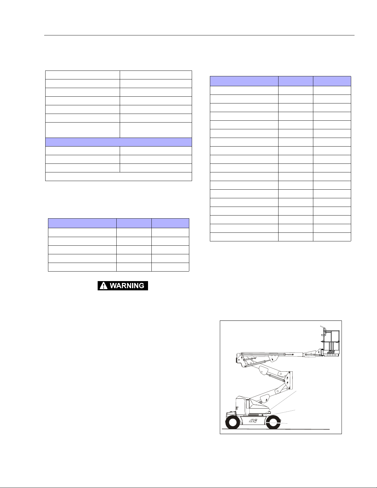
1.7 CRITICAL STABILITY WEIGHTS
Table 1-8. Mobil EAL 224H Specs
Type Synthetic Biodegradable
ISO Viscosity Grade 32/46
Specific Gravity .922
Pour Point, Max -25 °F (- 32°C )
Flash Point, Min. 428°F (220°C)
Operating Temp. 0 to 180°F (-17 to 162°C)
Weight 7.64 lb. per gal.
(0.9 kg per liter)
Viscosity
at 40° C 37 cSt
at 100° C 8.4 cSt
Viscosity Index 213
NOTE: Must be stored above 32°F (14°C)
Table 1-9. Critical Stability Weights
Component LB. KG.
Counterweight 3850 1746
Tire & Wheel (foam-filled) 207 94
Platform (4ft [1.2 m]) 90 41
Platform (5 ft [1.5 m]) 100 45
Battery (each) 120 54
Table 1-10. Major Component Weights
Component LB. KG.
Platform and Support 215 97.5
Upper Boom Complete 450 204
Mid Boom Complete 419 190
Lower Boom Complete 419 190
Upper Lift Cylinder 97 44
Mid Lift Cylinder 60 27
Lower Lif t Cylinde r 13 0 59
Master Cylinder 405 184
Slave Cylinder 432 196
Telescope Cylinder 103 47
Upper Upright 222 101
Lower Upright 93 42
Turntable 948 430
Battery Box (incl. batteries) 600 272
Chassis (w/ pneu. tires) 4295 1948
Chassis (w/ foam-filled tires) 4695 2130
Counterweight 3850 1746
Machine Complete 14480 6568
SERIAL NUMBER PLATE
SERIAL NUMBER FRAME
SERIAL NUMBER
TURNTABLE
SECTION 1 - SPECIFICATIONS
1.8 MAJOR COMPONENT WEIGHTS
DO NOT REPLACE ITEMS CRITICAL TO STABILITY WITH ITEMS OF DIFFERENT
WEIGHT OR SPECIFICATION (FOR EXAMPLE: BATTERIES, FILLED TIRES, PLATFORM) DO NOT MODIFY UNIT IN ANY WAY TO AFFECT STABILITY.
3121714 1-3
1.9 SERIAL NUMBER LOCATIONS
For machine identification, a serial number plate is affixed to
the left rear of frame, in front of left rear wheel. If the serial
number plate is damaged or missing, the machine serial number is stamped on the top left side of the frame and the top
left side of the turntable. In addition, the serial number is
stamped on top of the end of the upper boom, mid boom, and
lower boom at the left rear of the booms.
Figure 1-1. Serial Number Locations
Page 22
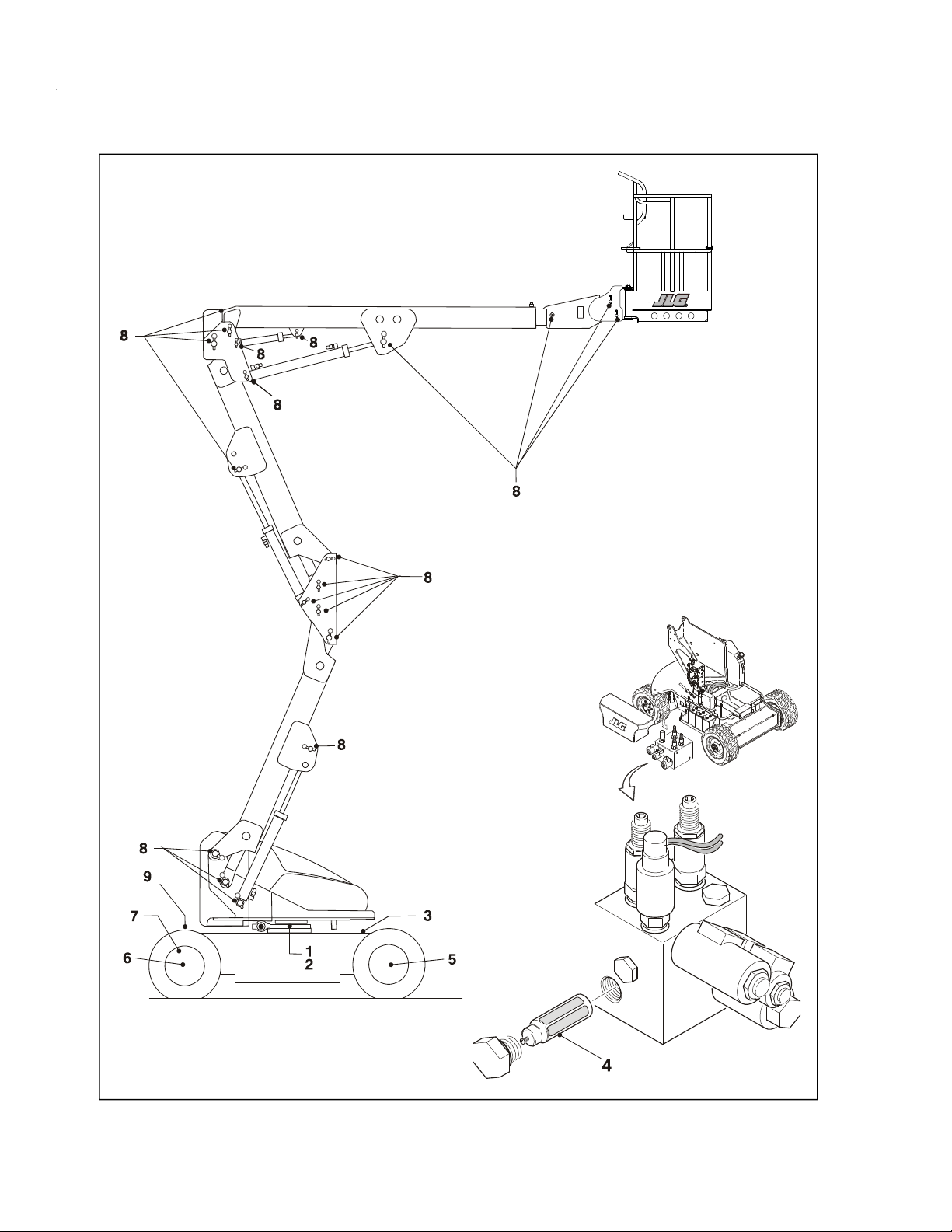
SECTION 1 - SPECIFICATIONS
Figure 1-2. Maintenance & Lubrication Diagram
1-4 3121714
Page 23
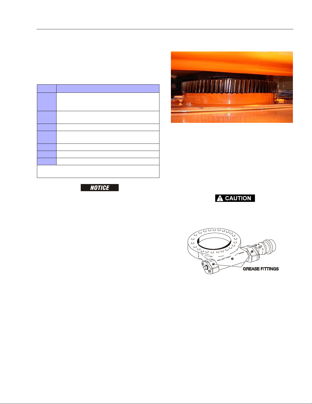
SECTION 1 - SPECIFICATIONS
Table 1-11. Lubrication Specifications
KEY SPECIFICATIONS
MPG Multipurpose Grease having a minimum dripping point of 350 degrees F.
Excellent water resistance and adhesive qualities; and being of ex treme
pressure type (Timken OK 40 lbs. minimum).
EPGL Extreme Pressure Gear Lube (oil) meeting API Service Classification GL-5
or Mil-Spec Mil-L-2105.
HO Hydraulic Oil. Mobil DTE-10
OG* Open Gear Lube - Tribol Molub-Alloy 936 Open Gear Compound. (JLG Part
No. 3020027)
BG* Bearing Grease (JLG Part No. 3020029) Mobilith SHA 460.
LL Synthetic Lithium Lubricant, Gredag 741 Grease. (JLG Part No. 3020022)
EO Engine (crankcase) Oil. Refer to Engine Operation Manual.
*MPG may be substituted for these lubricants, if necessary, but service intervals will be
reduced.
1.10 MAINTENANCE AND LUBRICATION
NOTE: The following numbers correspond to those in Figure 1-2.,
Maintenance & Lubrication Diagram.
LUBRICATION INTERVALS ARE BASED ON MACHINE OPERATION UNDER NORMAL CONDITIONS. FOR MACHINES USED IN MULTI-SHIFT OPERATIONS AND/
OR EXPOSED TO HOSTILE ENVIRONMENTS OR CONDITIONS, LUBRICATION
FREQUENCIES MUST BE INCREASED ACCORDINGLY.
2. Swing Bearing/Worm Gear Teeth
Lube Point(s) - Grease Fittings
Capacity - Spray On
Lube - OG or Mobiltac375NC
Interval - A/R
Comments - If necessary install grease fittings into worm
gear housing and grease bearings.
NOTE: OG will allow better cycle times than Mobiltac375NC,
however Mobiltac375NC must be used in dusty environments. If the swing function becomes noisy and/or rough
lubricate the bearing teeth.
DO NOT OVERGREASE BEARINGS. OVERGREASING BEARINGS WILL RESULT IN
BLOWING OUTER SEAL IN HOUSING.
1. Swing Bearing
Lube Point(s) - 2 Grease Fittings
Capacity - A/R
Lube - MPG
Interval - Every 3 months or 150 hrs of operation
Comments - Remote Access (Optional).
3121714 1-5
Page 24

SECTION 1 - SPECIFICATIONS
3. Hydraulic Tank
Interval - Change after first 50 hrs. and every 6 months
or 300 hrs. thereafter.
Comments - Under certain conditions, it may be necessary to replace the hydraulic filter on a more frequent
basis. A common symptom of a dirty filter is sluggishness experienced in hydraulic functions.
5. Wheel Drive Hub
Lube Point(s) - Fill Cap
Capacity - 4 Gal. (15.1 L)
Lube - HO
Interval - Check Level daily; Change every 2 years or
1200 hours of operation.
Comments - On new machines, those recently overhauled, or after changing hydraulic oil, operate all systems a minimum of two complete cycles and recheck
oil level in reservoir.
4. Hydraulic Return Filter
Lube Point(s) - Level/Fill Plug
Capacity - 17 oz. (1/2 Full)
Lube - EPGL
Interval - Check level every 3 months or 150 hrs of operation; change every 2 years or 1200 hours of operation.
1-6 3121714
Page 25
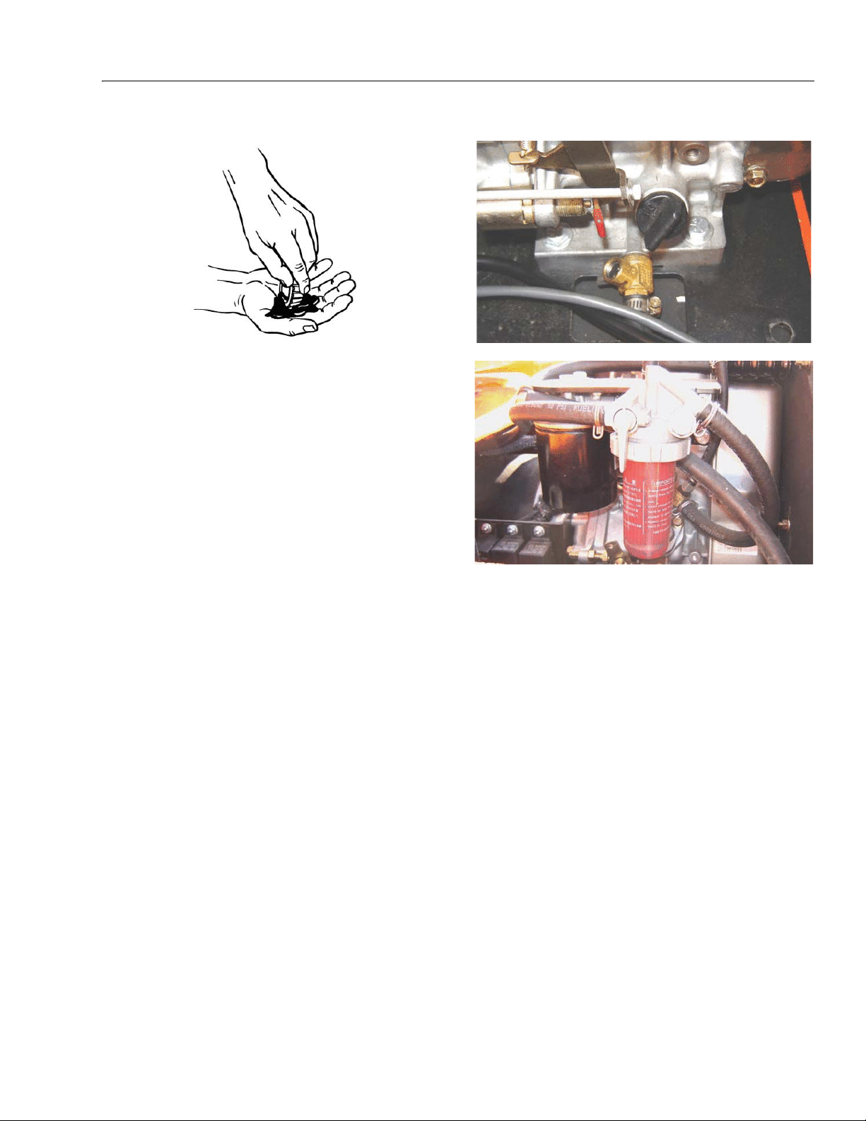
SECTION 1 - SPECIFICATIONS
6. Wheel Bearing
Lube Point(s) - Repack
Capacity - A/R
Lube - MPG
Interval - Every 2 years or 1200 hours of operation.
7. Spindles/Bushing
Capacity - A/R
Lube - Lithium Lubricant
Interval - Every 2 years or 1200 hours of operation
Comments - At Spindle/Bushing Replacement; Coat I.D.
of bushings prior to installing king pins.
8. Boom Pivot Pins/Bushing
Capacity - A/R
Lube - Lithium Lubricant
Interval - Every 2 years or 1200 hours of operation
Comments - At boom pivot pins/bushing replacement;
Coat I.D. of bushings prior to installing pivot pins.
9. Engine
Lube Point(s) - Fill Cap
Capacity - Refer to Engine Manual
Lube - EO
Interval - 3 Months or 150 hours of operation
Comments - Check level daily/Change in accordance
with engine manual.
3121714 1-7
Page 26
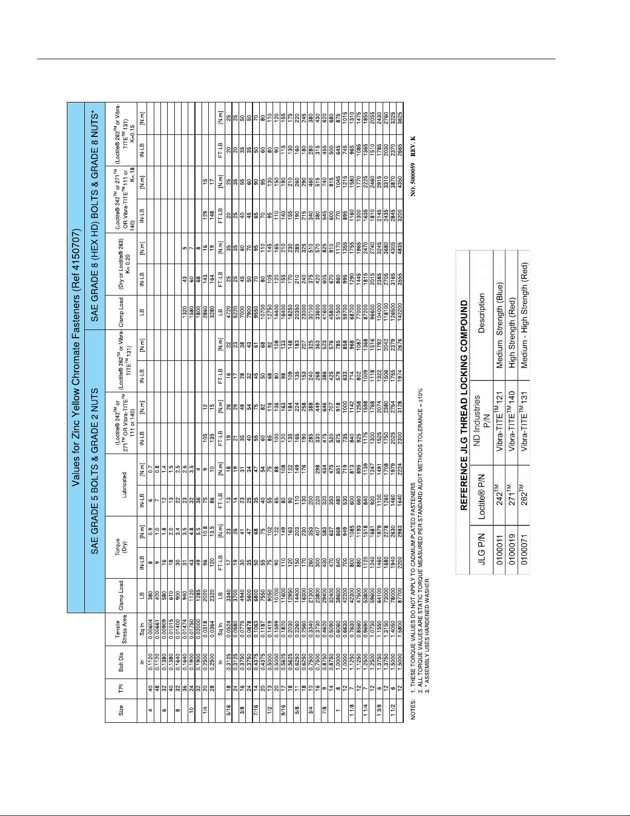
SECTION 1 - SPECIFICATIONS
Tor q u e
To r qu e
Tor q u e
To r qu e
Torque Torque
Figure 1-3. Torque Chart (SAE Fasteners - Sheet 1 of 5)
1-8 3121714
Page 27
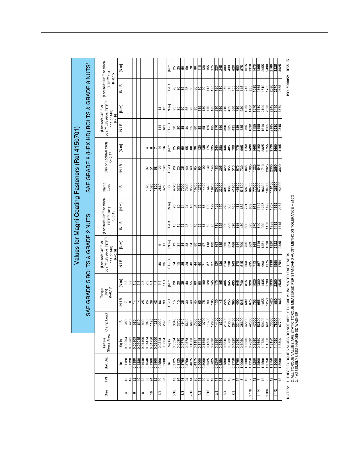
SECTION 1 - SPECIFICATIONS
Tor q u e
Tor qu e
Tor q ue
Tor qu e
To r qu e
Figure 1-4. Torque Chart (SAE Fasteners - Sheet 2 of 5)
3121714 1-9
Page 28
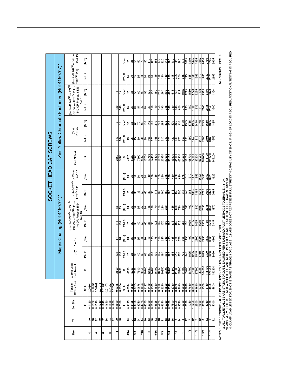
SECTION 1 - SPECIFICATIONS
Clamp LoadTo r que
To r qu e
Tor q ue
Torque
Tor que
Tor q u e
Figure 1-5. Torque Chart (SAE Fasteners - Sheet 3 of 5)
1-10 3121714
Page 29
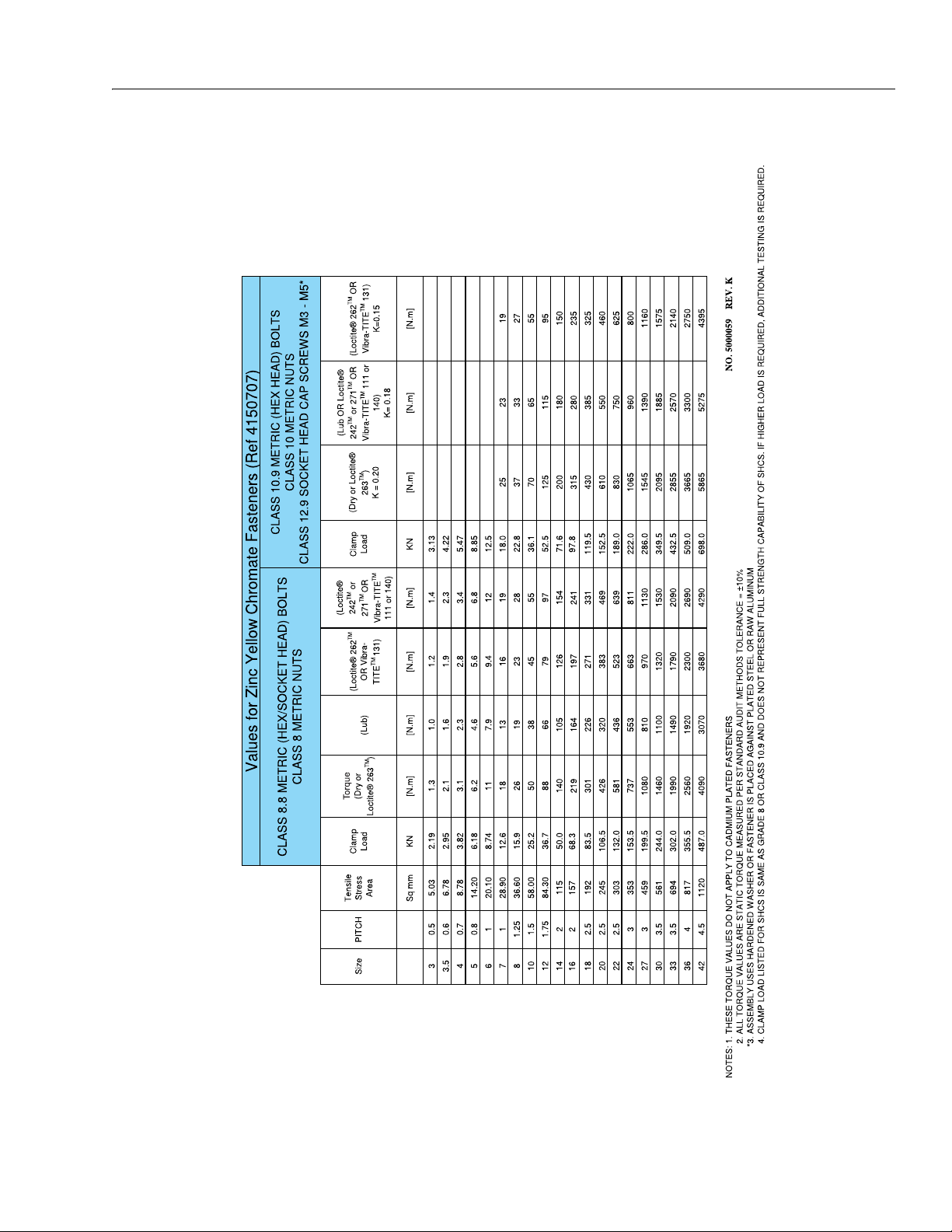
SECTION 1 - SPECIFICATIONS
To r qu e
To r qu e
Torque
To r q ue
To r qu e
To r q ue
Figure 1-6. Torque Chart (METRIC Fasteners - Sheet 4 of 5)
3121714 1-11
Page 30
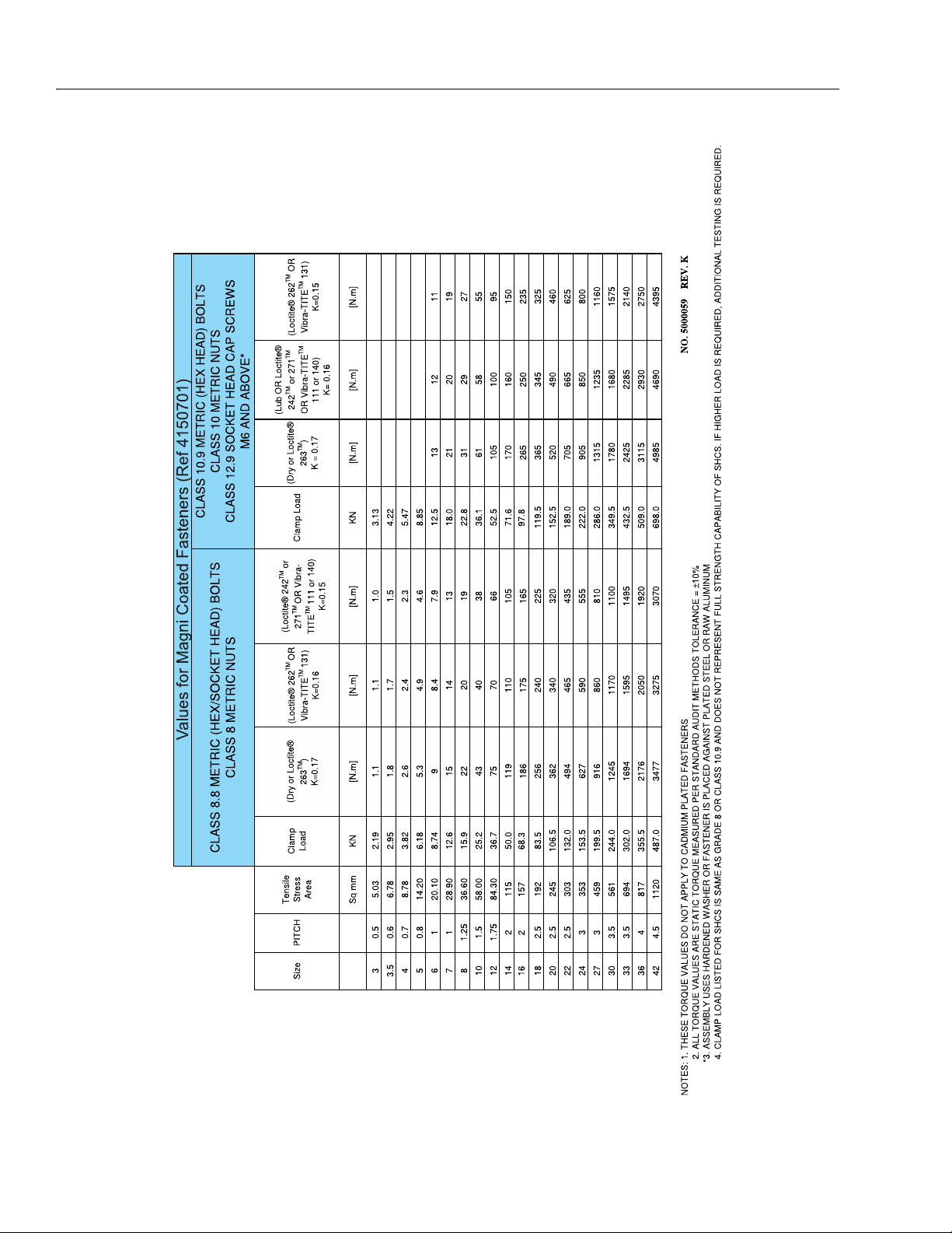
SECTION 1 - SPECIFICATIONS
Torque Torque
Tor qu e
To r qu e
To r qu e
To r q ue
Figure 1-7. Torque Chart (METRIC Fasteners - Sheet 5 of 5)
1-12 3121714
Page 31

SECTION 2. GENERAL
SECTION 2 - GENERAL
2.1 MACHINE PREPARATION, INSPECTION, AND MAINTENANCE
General
This section provides the necessary information needed by
those personnel that are responsible to place the machine in
operation readiness and maintain its safe operating condition.
For maximum service life and safe operation, ensure that all
the necessary inspections and maintenance have been completed before placing the machine into service. With proper
care, maintenance, and inspections performed per JLG's recommendations, and with any and all discrepancies corrected,
this product will be fit for continued use.
Preparation, Inspection, and Maintenance
It is important to establish and conform to a comprehensive
inspection and preventive maintenance program. The following table outlines the periodic machine inspections and maintenance recommended by JLG Industries, Inc. Consult your
national, regional, or local regulations for further requirements
for aerial work platforms. The frequency of inspections and
maintenance must be increased as environment, severity and
frequency of usage requires.
Pre-Start Inspection
It is the User’s or Operator’s primary responsibility to perform a
Pre-Start Inspection of the machine prior to use daily or at
each change of operator. Reference the Operator’s and Safety
Manual for completion procedures for the Pre-Start Inspection. The Operator and Safety Manual must be read in its
entirety and understood prior to performing the Pre-Start
Inspection.
Pre-Delivery Inspection and Frequent Inspection
The Pre-Delivery Inspection and Frequent Inspection shall be
performed by a qualified JLG equipment mechanic. JLG Industries, Inc. recognizes a qualified JLG equipment mechanic as a
person who, by possession of a recognized degree, certificate,
extensive knowledge, training, or experience, has successfully
demonstrated the ability and proficiency to service, repair, and
maintain the subject JLG product model.
Reference the JLG Pre-Delivery and Frequent Inspection Form
and the Inspection and Preventative Maintenance Schedule
for items requiring inspection during the performance of
these inspections. Reference the appropriate areas of this
manual for servicing and maintenance procedures.
Annual Machine Inspection
The Annual Machine Inspection must be performed by a Factory-Trained Service Technician on an annual basis, no later
than thirteen (13) months from the date of the prior Annual
Machine Inspection. JLG Industries, Inc. recognizes a FactoryTrained Service Technician as a person who has successfully
completed the JLG Service Training School for the subject JLG
product model. Reference the machine Service and Maintenance Manual and appropriate JLG inspection form for performance of this inspection.
Reference the JLG Annual Machine Inspection Form and the
Inspection and Preventative Maintenance Schedule for items
requiring inspection during the performance of this inspection. Reference the appropriate areas of this manual for servicing and maintenance procedures.
For the purpose of receiving safety-related bulletins, it is
important that JLG Industries, Inc. has updated ownership
information for each machine. When performing each Annual
Machine Inspection, notify JLG Industries, Inc. of the current
machine ownership.
Preventative Maintenance
In conjunction with the specified inspections, maintenance
shall be performed by a qualified JLG equipment mechanic.
JLG Industries, Inc. recognizes a qualified JLG equipment
mechanic as a person who, by possession of a recognized
degree, certificate, extensive knowledge, training, or experience, has successfully demonstrated the ability and proficiency to service, repair, and maintain the subject JLG product
model.
Reference the Preventative Maintenance Schedule and the
appropriate areas of this manual for servicing and maintenance procedures. The frequency of service and maintenance
must be increased as environment, severity and frequency of
usage requires.
The Pre-Delivery Inspection and Frequent Inspection procedures are performed in the same manner, but at different
times. The Pre-Delivery Inspection shall be performed prior to
each sale, lease, or rental delivery. The Frequent Inspection
shall be accomplished for each machine in service for 3
months or 150 hours (whichever comes first); out of service for
a period of more than 3 months; or when purchased used. The
frequency of this inspection must be increased as environment, severity and frequency of usage requires.
3121714 2-1
Page 32

SECTION 2 - GENERAL
Table 2-1. Inspection and Maintenance
Type Frequency
Pre-Start Inspection Prior to use each day; or
At each Operator change.
Pre-Delivery Inspecti on Prior to each sale, lea se, or
rental delivery.
Frequent Inspection In service for 3 months or 150 hours, whichever
comes first; or
Out of service for a period of more than 3 months; or
purchased used.
Annual Machine
Inspection
Preventive
Maintenance
Annually, no later than 13 months from the date of
the prior inspection.
At intervals as specified in the Service and Mainte-
nance Manual.
2.2 SERVICE AND GUIDELINES
General
The following information is provided to assist you in the use
and application of servicing and maintenance procedures
contained in this book.
Safety and Workmanship
Your safety, and that of others, is the first consideration when
engaging in the maintenance of equipment. Always be conscious of weight. Never attempt to move heavy parts without
the aid of a mechanical device. Do not allow heavy objects to
rest in an unstable position. When raising a portion of the
equipment, ensure that adequate support is provided.
Cleanliness
Primary
Responsibility
User or Operator User or Operator Operation and Safety Manual
Owner, Dealer, or User Qualified JLG Mechanic Service and Maintenance Manual
Owner, Dealer, or User Qualified JLG Mechanic Service and Maintenance Manual
Owner, Dealer, or User Factory-Trained Service
Owner, Dealer, or User Qualified JLG Mechanic Service and Maintenance Manual
2. At any time when air, fuel, or oil lines are disconnected,
clear adjacent areas as well as the openings and fittings
themselves. As soon as a line or component is disconnected, cap or cover all openings to prevent entry of foreign matter.
3. Clean and inspect all parts during servicing or maintenance, and assure that all passages and openings are
unobstructed. Cover all parts to keep them clean. Be
sure all parts are clean before they are installed. New
parts should remain in their containers until they are
ready to be used.
Service
Qualification
Technician
(Recommended)
Reference
and applicable JLG inspection form.
and applicable JLG inspection form.
Service and Maintenance Manual
and applicable JLG inspection form.
Components Removal and Installation
1. Use adjustable lifting devices, whenever possible, if
mechanical assistance is required. All slings (chains,
cables, etc.) should be parallel to each other and as near
perpendicular as possible to top of part being lifted.
1. The most important single item in preserving the long
service life of a machine is to keep dirt and foreign materials out of the vital components. Precautions have been
taken to safeguard against this. Shields, covers, seals,
and filters are provided to keep air, fuel, and oil supplies
clean; however, these items must be maintained on a
scheduled basis in order to function properly.
2. Should it be necessary to remove a component on an
angle, keep in mind that the capacity of an eyebolt or
similar bracket lessens, as the angle between the supporting structure and the component becomes less
than 90 degrees.
3. If a part resists removal, check to see whether all nuts,
bolts, cables, brackets, wiring, etc., have been removed
and that no adjacent parts are interfering.
2-2 3121714
Page 33

SECTION 2 - GENERAL
Component Disassembly and Reassembly
When disassembling or reassembling a component, complete
the procedural steps in sequence. Do not partially disassemble
or assemble one part, then start on another. Always recheck
your work to assure that nothing has been overlooked. Do not
make any adjustments, other than those recommended, without obtaining proper approval.
Pressure-Fit Parts
When assembling pressure-fit parts, use an anti-seize or
molybdenum disulfide base compound to lubricate the mating surface.
Bearings
1. When a bearing is removed, cover it to keep out dirt and
abrasives. Clean bearings in nonflammable cleaning solvent and allow to drip dry. Compressed air can be used
but do not spin the bearing.
2. Discard bearings if the races and balls (or rollers) are pitted, scored, or burned.
3. If bearing is found to be serviceable, apply a light coat of
oil and wrap it in clean (waxed) paper. Do not unwrap
reusable or new bearings until they are ready to install.
4. Lubricate new or used serviceable bearings before
installation. When pressing a bearing into a retainer or
bore, apply pressure to the outer race. If the bearing is to
be installed on a shaft, apply pressure to the inner race.
Gaskets
Check that holes in gaskets align with openings in the mating
parts. If it becomes necessary to hand-fabricate a gasket, use
gasket material or stock of equivalent material and thickness.
Be sure to cut holes in the right location, as blank gaskets can
cause serious system damage.
Bolt Usage and Torque Application
SELF LOCKING FASTENERS, SUCH AS NYLON INSERT AND THREAD DEFORMING
LOCKNUTS, ARE NOT INTENDED TO BE REINSTALLED AFTER REMOVAL.
1. Use bolts of proper length. A bolt which is too long will
bottom before the head is tight against its related part. If
a bolt is too short, there will not be enough thread area
to engage and hold the part properly. When replacing
bolts, use only those having the same specifications of
the original, or one which is equivalent.
2. Unless specific torque requirements are given within the
text, standard torque values should be used on heattreated bolts, studs, and steel nuts, in accordance with
recommended shop practices. (See Torque Chart Section 1.)
Hydraulic Lines and Electrical Wiring
Clearly mark or tag hydraulic lines and electrical wiring, as well
as their receptacles, when disconnecting or removing them
from the unit. This will assure that they are correctly reinstalled.
Hydraulic System
1. Keep the system clean. If evidence of metal or rubber
particles are found in the hydraulic system, drain and
flush the entire system.
2. Disassemble and reassemble parts on clean work surface. Clean all metal parts with non-flammable cleaning
solvent. Lubricate components, as required, to aid
assembly.
3121714 2-3
Page 34

SECTION 2 - GENERAL
Lubrication
Service applicable components with the amount, type, and
grade of lubricant recommended in this manual, at the specified intervals. When recommended lubricants are not available, consult your local supplier for an equivalent that meets
or exceeds the specifications listed.
Battery
Clean battery, using a non-metallic brush and a solution of
baking soda and water. Rinse with clean water. After cleaning,
thoroughly dry battery and coat terminals with an anti corrosion compound.
Lubrication and Servicing
Components and assemblies requiring lubrication and servicing are shown in the Lubrication Chart in Section 1.
2.3 LUBRICATION AND INFORMATION
Hydraulic System
1. The primary enemy of a hydraulic system is contamination. Contaminants enter the system by various means,
e.g., using inadequate hydraulic oil, allowing moisture,
grease, filings, sealing components, sand, etc., to enter
when performing maintenance, or by permitting the
pump to cavitate due to insufficient system warm-up or
leaks in the pump supply (suction) lines.
2. The design and manufacturing tolerances of the component working parts are very close, therefore, even the
smallest amount of dirt or foreign matter entering a system can cause wear or damage to the components and
generally results in faulty operation. Every precaution
must be taken to keep hydraulic oil clean, including
reserve oil in storage. Hydraulic system filters should be
checked, cleaned, and/or replaced as necessary, at the
specified intervals required in the Lubrication Chart in
Section 1. Always examine filters for evidence of metal
particles.
3. Cloudy oils indicate a high moisture content which permits organic growth, resulting in oxidation or corrosion.
If this condition occurs, the system must be drained,
flushed, and refilled with clean oil.
Hydraulic Oil
1. Refer to Section 1 for recommendations for viscosity
ranges.
2. JLG recommends Mobil DTE-10 hydraulic oil, which has
an SAE viscosity of 10W and a viscosity index of 168.
NOTE: Start-up of hydraulic system with oil temperatures below -
20 degrees F (-29 degrees C) is not recommended. If it is
necessary to start the system in a sub-zero environment, it
will be necessary to heat the oil with a low density, 100VAC
heater to a minimum temperature of -20 degrees F (-29
degrees C).
Changing Hydraulic Oil
1. Filter elements must be changed after the first 50 hours
of operation and every 300 hours thereafter. If it is necessary to change the oil, use only those oils meeting or
exceeding the specifications appearing in this manual. If
unable to obtain the same type of oil supplied with the
machine, consult local supplier for assistance in selecting the proper equivalent. Avoid mixing petroleum and
synthetic base oils.
2. Use every precaution to keep the hydraulic oil clean. If
the oil must be poured from the original container into
another, be sure to clean all possible contaminants from
the service container. Always clean the mesh element of
the filter and replace the cartridge any time the system
oil is changed.
3. While the unit is shut down, a good preventive maintenance measure is to make a thorough inspection of all
hydraulic components, lines, fittings, etc., as well as a
functional check of each system, before placing the
machine back in service.
Lubrication Specifications
Specified lubricants, as recommended by the component
manufacturers, are always the best choice, however, multi-purpose greases usually have the qualities which meet a variety of
single purpose grease requirements. Should any question
arise, regarding the use of greases in maintenance stock, consult your local supplier for evaluation. Refer to Section 1 for an
explanation of the lubricant key designations appearing in the
Lubrication Chart.
4. It is not advisable to mix oils of different brands or types,
as they may not contain the same required additives or
be of comparable viscosities. Good grade mineral oils,
with viscosities suited to the ambient temperatures in
which the machine is operating, are recommended for
use.
NOTE: Metal particles may appear in the oil or filters of new
machines due to the wear-in of meshing components.
2-4 3121714
Page 35

SECTION 2 - GENERAL
2.4 CYLINDER DRIFT
Theory
When a hydraulic cylinder is supporting a load, cylinder drift
may occur as a result of any of the circumstances below:
• Normal leakage of load holding valves or malfunction of
load holding valves. See Cylinder Leakage Test and Table 22, Cylinder Drift below for evaluation.
• Damaged or worn piston seal.
• Normal thermal expansion and contraction of the hydraulic oil within cylinders (See Cylinder Thermal Drift below).
The first two circumstances may result in cylinder movement
due to oil leakage out of the cylinder externally or by leaking
back to tank or due to oil leaking internally from one cylinder
chamber to the other.
Thermal expansion or contraction of oil in hydraulic cylinders
is a normal occurrence and does not result in oil leaking out of
the cylinder or leaking internally from one cylinder chamber
to the other. Thermal expansion or contraction is the tendency
for materials to change size in response to a change in temperature.
Cylinder Leakage Test
Cylinder oil must be at stabilized ambient temperature
before beginning this test.
Measure drift at cylinder rod with a calibrated dial indicator.
In an area free of obstructions, cylinder must have load
applied and appropriately positioned to detect drift.
Cylinder leakage is acceptable if it passes this test.
Table 2-2. Cylinder Drift
Cylinder Bore Diameter
inches mm inches mm
3 76.2 0.026 0.66
3.5 89 0.019 0.48
4 101.6 0.015 0.38
5 127 0.009 0.22
6 152.4 0.006 0.15
7 177.8 0.005 0.13
8 203.2 0.004 0.10
9 228.6 0.003 0.08
NOTE: This information is based on 6 drops per minute cylinder
leakage.
Max. Acceptable Drift
in 10 Minutes
Cylinder Thermal Drift
The oil in all hydraulic cylinders will expand or contract due to
thermal effects over time and may result in changes to the
boom and/or platform position while the machine is stationary. These effects occur as the cylinder oil changes temperature, usually from a higher oil temperature as it cools and
approaches the ambient air temperature. Results of these
effects are related to several factors including cylinder length
and change in temperature over the time the cylinder remains
stationary.
3121714 2-5
Page 36

SECTION 2 - GENERAL
2.5 PINS AND COMPOSITE BEARING REPAIR GUIDELINES
Filament wound bearings.
1. Pinned joints should be disassembled and inspected if
the following occurs:
a. Excessive sloppiness in joints.
b. Noise originating from the joint during operation.
2. Filament wound bearings should be replaced if any of
the following is observed:
a. Frayed or separated fibers on the liner surface.
b. Cracked or damaged liner backing.
c. Bearings that have moved or spun in their housing.
d. Debris embedded in liner surface.
3. Pins should be replaced if any of the following is
observed (pin should be properly cleaned prior to
inspection):
a. Detectable wear in the bearing area.
b. Flaking, pealing, scoring, or scratches on the pin sur-
face.
c. Rusting of the pin in the bearing area.
4. Re-assembly of pinned joints using filament wound
bearings.
a. Housing should be blown out to remove all dirt and
debris. Bearings and bearing housings must be free
of all contamination.
b. Bearing / pins should be cleaned with a solvent to
remove all grease and oil. Filament wound bearing
are a dry joint and should not be lubricated unless
otherwise instructed (i.e. sheave pins).
c. Pins should be inspected to ensure it is free of burrs,
nicks, and scratches which would damage the bearing during installation and operation.
2.6 WELDING ON JLG EQUIPMENT
NOTE: This instruction applies to repairs, or modifications to the
machine and to welding performed from the machine on
an external structure, or component,
Do the Following When Welding on JLG Equipment
• Disconnect the battery.
• Ground only to structure being welded.
Do NOT Do the Following When Welding on JLG Equipment
• Ground on frame and weld on any other area than the
chassis.
• Ground on turntable and weld on any other area than the
turntable.
• Ground on the platform/support and weld on any other
area than the platform/support.
• Ground on a specific boom section and weld on any other
area than that specific boom section.
• Allow pins, wear pads, wire ropes, bearings, gearing, seals,
valves, electrical wiring, or hoses to be between the
grounding position and the welded area.
FAILURE TO COMPLY WITH THE ABOVE REQUIREMENTS MAY RESULT IN COMPONENT DAMAGE (I.E. ELECTRONIC MODULES, SWING BEARING, COLLECTOR
RING, BOOM WIRE ROPES ETC.)
2-6 3121714
Page 37

Table 2-3. Inspection and Preventive Maintenance Schedule
INTERVAL
AREA
Pre-Delivery
or Frequent
Inspection
1
2
Annual
(Yearly)
Inspection
3
Boom Assembly
Boom Weldments 1,2,4 1,2,4
Hose/Cable Carrier Installations 1,2,9,12 1,2,9,12
Pivot Pins and Pin Retainers 1,2 1,2
Sheaves, Sheave Pins 1,2 1,2
Bearings 1,2 1,2
Wear Pad s 1,2 1,2
Covers or Shi elds 1,2 1,2
Extend/Retract Chain or Cable Systems 1,2,3 1,2,3
Platform Assembly
Platform 1,2
Railing 1 1,2
Gate 1,5 1,5
Floor 1 1,2
Rotator 5,9,15
Lanyard Anchorage Point 1,2,10 1,2,10
Turntable Assembly
Swing Bearing or Worm Gear 1,2,14 1,2,3,13,14
Oil Coupling 9
Swing Drive System 11 11
Turntable Lock 1,2,5 1,2,5
Hood, Hood Props, Hood Latches 5 1,2,5
Chassis Assembly
Tires 16,17,18 16,17,18
Wheel Nuts/Bolts 15 15
Wheel Bearings 14,24
Oscillating Axle/Lockout Cylinder Systems 5,8
Outrigger or Extendable Axle Systems 5,8 5,8
Steer Components
Drive Motors
Drive Hubs 11 11
SECTION 2 - GENERAL
Every 2
Yea rs
3121714 2-7
Page 38

SECTION 2 - GENERAL
Functions/Controls
Platform Controls 5,6 6
Ground Controls 5,6 6
Function Control Locks, Guards, or Detents 1,5 5
Footsw itch 5 5
Emergency Stop Switches (Ground & Platform) 5 5
Function Limit or Cutout Switch Systems 5 5
Capacity Indicator 5
Drive Brakes 5
Swing Brakes 5
Boom Synchronization/Sequencing Systems 5
Manual Descent or Auxiliar y Power 5 5
Power Sys tem
Engine Idle, Throttle, and RPM 3 3
Engine Fluids (Oil, Coolant, Fuel) 9,11 11
Air/Fuel Filter 1,7 7
Exhaust System 1,9 9
Batteries 1,9 19
Battery Fluid 11 11
Battery Charger 5 5
Fuel Reservoir, Cap, and Breather 1,2,5 1,5
Hydraulic/Electric System
Hydraulic Pumps 1,2,9
Hydraulic Cylinders 1,2,7,9 1,2,9
Cylinder Attachment Pins and Pin Retainers 1,2,9 1,2
Hydraulic Hoses, Lines, and Fittings 1,2,9,12 1,2,9,12
Hydraulic Reservoir, Cap, and Breather 1,2,5,9 1,5 24
Hydraulic Filter 1,7,9 7
Hydraulic Fluid 7,11 7,11
Electrical Connections 1,20 20
Instruments, Gauges, Switches, Lights, Horn 1 5,23
General
Operators and Safety Manuals in Storage Box 21 21
ANSI and EMI Manuals/Handbooks Installed 21
Table 2-3. Inspection and Preventive Maintenance Schedule
INTERVAL
AREA
Pre-Delivery
or Frequent
Inspection
1
2
Annual
(Yearly)
Inspection
3
Every 2
Yea rs
2-8 3121714
Page 39

Table 2-3. Inspection and Preventive Maintenance Schedule
AREA
Pre-Delivery
or Frequent
Inspection
1
2
Inspection
Capacity Decals Installed, Secure, Legible 21 21
All Decals/Placards Installed, Secure, Legible 21 21
Walk-Around Inspection Performed
Annual Machine Inspection Due 21
No Unauthorized Modifications or Additions 21 21
All Relevant Safety Publications Incorporated 21 21
General Structural Condition a nd Welds 2,4 2,4
All Fasteners, Pins, Shields, and Covers 1,2 1,2
Grease and Lubricate to Specifications 22 22
Function Test of All Systems 21 21, 22
Paint and Appearance 7 7
Stamp Inspection Date on Frame 22
Notify JLG of Machine Ownership 22
Footno tes:
1
Prior to each sale, lease, or delivery
2
In service for 3 months or 150 Hours; or Ou t of service for 3 months or more; or Purchased used
3
Annually, no later than 13 months from the date of the prior inspection
Performance Codes:
1 - Check for proper and secure installation
2 - Visual inspection for damage, cracks, distortion or excessive wear
3 - Check for proper adjustment
4 - Check for cracked or broken welds
5 - Operates Properly
6 - Returns to neutral or "off" position when released
7 - Clean and free of debris
8 - Interlocks function properly
9 - Check for signs of leakage
10 - Decals installed and legible
11 - Check for proper fluid level
12 - Check for chafing and proper routi ng
13 - Check for proper tolerances
14 - Properly lubricated
15 - Torqued to proper specification
16 - No gouges, excessive wear, or cords showing
17 - Properly inflated and seated around rim
18 - Proper and authorized components
19 - Fully charged
20 - No loose connections, corrosion, or abrasions
21 - Verify
22 - Perform
23 - Sealed Properly
24 - Drain, Clean, Refill
INTERVAL
Annual
(Yearly)
SECTION 2 - GENERAL
3
Every 2
Yea rs
3121714 2-9
Page 40

SECTION 2 - GENERAL
AMBIENT AIR
TEM PERATURE
(HYD. OIL TANK TEMP.)
IF EI THER OR BOTH CONDITIONS
EXI ST JLG HIGHLY RECO MME NDS
THE ADDI TI O N O F A HYDRA ULIC
OIL COOLER (CONSULT JLG SERVICE
-40 F(-40 C)
-30 F(-34 C)
-20 F(-29 C)
-10 F(-23 C)
0F(-18C)
10 F( -12 C)
20 F( -7 C )
30 F( -1 C )
40 F( 4 C )
50 F( 10 C)
60 F( 16 C)
70 F( 21 C)
80 F( 27 C)
90 F( 32 C)
100 F (38 C )
110 F (43 C )
120 F (49 C )
180 F(82 C)
PROLONGED OPERATION IN
AMBIENT AIR TEMPERATURES
OF 100 F(38 C) OR ABOVE.
EXT ENDED DRIV ING WIT H
HYDRAULI C OIL TANK
TEMPERATURES OF 180 F
(82 C) OR ABOVE.
NO OPERATIO N BELOW THIS
AMBIENT TEMPERATURE
MOBIL 424 10W-30
HYDRAULIC
SPECI FICATI ONS
NO OPERATIO N ABOVE THIS
AMBIENT TEMPERATURE
DO NOT START UP HYDRAULIC SYSTEM
WIT HOUT HEATING AIDS WITH MOBILE 424
HYDRAULI C OIL B ELO W T HIS T EMPERAT URE
DO NOT START UP HYDRAULIC SYSTEM
WI THOUT HEATI NG AI DS AND CO LD WE AT HER
HYDRAULI C OIL B ELO W T HIS T EMP ERATURE
EXXON UNIVIS HVI 26
MOBI L DTE 13
-40 F(-40 C)
-30 F(-34 C)
-20 F(-29 C)
-10 F(-23 C)
0 F(-18 C)
10 F(-12 C)
20 F(-7 C)
30 F(-1 C)
40 F(4 C)
50 F(10 C)
60 F(16 C)
70 F(21 C)
80 F(27 C)
90 F(32 C)
100 F(38 C)
110 F(43 C )
120 F(49 C)
ENGINE
SPECIFICATIONS
ENGINE WILL START AND OPERATE UNAIDED AT THIS
TEMP ERATURE WITH THE RECOMME NDED FLUIDS AN D A
FULLY CHAR GED B ATTER Y.
AMBIEN T AIR
TEMPERATURE
SAE 30
S AE 20SAE 5W-30
SAE 10W-30
SAE 10
NO OPERATION BEL OW THIS
AMBIENT TEMPERATURE
NO OPERATION ABOVE THIS
AMBIENT TEMPERATURE
[*]
[#]
NOT E:
1) RECOMMENDATIO NS ARE FOR AMBIENT TEMPERATURES
CONSISTANTLY WITHIN SHOWN LIMITS.
2) ALL VALUES ARE ASSUMED TO BE AT SEA LEVEL.
3) WITH COLD WEATHER PKG, GASO LINE COLD START
POSSIBLE @ 5°F(-15°C).
[*] - KUBOTA GAS ENGINE
[#] - KUBOTA DIESEL ENGINE
Figure 2-1. Engine Operating Temperature Specifications - Kubota
2-10 3121714
Page 41

SECTION 3. CHASSIS & TURNTABLE
SECTION 3 - CHASSIS & TURNTABLE
3.1 TIRES & WHEELS
Tire Inflation
The air pressure for pneumatic tires must be equal to the air
pressure that is stenciled on the side of the JLG product or rim
decal for safe and proper operational characteristics.
Tire Damage
For pneumatic tires, JLG Industries, Inc. recommends that
when any cut, rip, or tear is discovered that exposes sidewall or
tread area cords in the tire, measures must be taken to remove
the JLG product from service immediately. Arrangements
must be made for replacement of the tire or tire assembly.
For polyurethane foam filled tires, JLG Industries, Inc. recommends that when any of the following are discovered, measures must be taken to remove the JLG product from service
immediately and arrangements must be made for replacement of the tire or tire assembly.
• a smooth, even cut through the cord plies which
exceeds 3 inches (7.5 cm) in total length
• any tears or rips (ragged edges) in the cord plies
which exceeds 1 inch (2.5 cm) in any direction
• any punctures which exceed 1 inch in diameter
• any damage to the bead area cords of the tire
If a tire is damaged but is within the above noted criteria, the
tire must be inspected on a daily basis to insure the damage
has not propagated beyond the allowable criteria.
Tire Replacement
JLG recommends a replacement tire be the same size, ply and
brand as originally installed on the machine. Please refer to the
JLG Parts Manual for the part number of the approved tires for
a particular machine model. If not using a JLG approved
replacement tire, we recommend that replacement tires have
the following characteristics:
Unless specifically approved by JLG Industries Inc. do not
replace a foam filled or ballast filled tire assembly with a pneumatic tire. When selecting and installing a replacement tire,
ensure that all tires are inflated to the pressure recommended
by JLG. Due to size variations between tire brands, both tires
on the same axle should be the same.
Wheel Replacement
The rims installed on each product model have been designed
for stability requirements which consist of track width, tire
pressure, and load capacity. Size changes such as rim width,
center piece location, larger or smaller diameter, etc., without
written factory recommendations, may result in an unsafe
condition regarding stability.
Wheel Installation
It is extremely important to apply and maintain proper wheel
mounting torque.
WHEEL NUTS MUST BE INSTALLED AND MAINTAINED AT THE PROPER TORQUE
TO PREVENT LOOSE WHEELS, BROKEN STUDS, AND POSSIBLE DANGEROUS
SEPARATION OF WHEEL FROM THE AXLE. BE SURE TO USE ONLY THE NUTS
MATCHED TO THE CONE ANGLE OF THE WHEEL.
Tighten the lug nuts to the proper torque to prevent wheels
from coming loose. Use a torque wrench to tighten the fasteners. If you do not have a torque wrench, tighten the fasteners
with a lug wrench, then immediately have a service garage or
dealer tighten the lug nuts to the proper torque. Over-tightening will result in breaking the studs or permanently deforming
the mounting stud holes in the wheels. The proper procedure
for attaching wheels is as follows:
1. Start all nuts by hand to prevent cross threading. DO
NOT use a lubricant on threads or nuts.
2. Tighten nuts in the following sequence:
• Equal or greater ply/load rating and size of original
• Tire tread contact width equal or greater than original
• Wheel diameter, width, and offset dimensions equal
to the original
• Approved for the application by the tire manufacturer (including inflation pressure and maximum
tire load)
3121714 3-1
Page 42

SECTION 3 - CHASSIS & TURNTABLE
3. The tightening of the nuts should be done in stages. Following the recommended sequence, tighten nuts per
wheel torque chart.
Table 3-1. Wheel Torque Chart
TORQUE SEQUENCE
1st Stage 2nd Stage 3rd Stage
40 ft. lbs.
(55 Nm)
4. Wheel nuts should be torqued after first 50 hours of
operation and after each wheel removal. Check torque
every 3 months or 150 hours of operation.
100 ft. lbs.
(130 Nm)
170 ft. lbs.
(255 Nm)
3.2 SPINDLE
Setting Wheel Bearing End Play
BE SURE NOT TO OVER-TIGHTEN THE SPINDLE NUT.
1. Tighten the spindle nut to assure the bearings are properly seated.
2. Loosen the spindle nut completely until the nut can be
turned by hand.
3. Tighten the spindle nut by hand using a socket without
rotating the hub.
4. If the cotter pin can be assembled with the spindle nut
finger tight, insert cotter pin without backing the nut
off. If the cotter pin cannot be assembled with the spindle nut hand tight, tighten the spindle nut to the nearest
available slot and insert cotter pin. If more than ½ of the
cotter pin hole in the spindle can be seen in a slot, back
nut off to nearest slot and insert pin.
7. Insert the dust cap and check to make sure the cotter
pin is not going to interfere. Cap must be pressed all the
way down. The unit should be checked again to assure it
spins freely after the dust cap is installed.
Specifications
The end play specification is 0.001”/0.010" (0.025 / 0.254
mm) for all units.
Checking
The end play is checked by clamping the spindle in a fixture or
vise and moving the hub parallel to the spindle centerline
without rocking the hub. If the end play is set properly the following should apply:
1. Hub should rotate freely when spun by hand.
2. The hub should not be noticeably loose when moved
parallel with spindle centerline.
Greasing Requirements
Hub assemblies shall have grease packed in the bearings via
an appropriate greasing spindle or by hand. In either method,
the bearing must be greased so the grease is forced through
the entire bearing cavity and through the rollers of both inner
and outer bearings.
Dust or grease caps used shall have grease applied to the
inside of the cap.
The bearing cavity shall be filled 50 - 80% full of grease on all
applications.
Dust or grease caps shall also be filled 10-20% full of grease on
all applications prior to final assembly.
Visually verify that grease has flowed all rollers of the inner
and outer bearings.
5. Check the unit for end play by moving the hub up &
down parallel along the centerline of the spindle. If you
can feel excessive end play (over the 0.010" [0.25 mm]
specification), recheck the nut to see what is causing the
excessive end play. Keep in mind that there can be some
movement and still be within the 0.010" (0.25 mm) maximum specification. If there is no way of getting the
excessive end play out by using your fingers, a socket or
wrench may have to be used to set the end play.
6. The units should be checked visually to make sure the
cotter pins are installed and that the correct components have been used. Each unit must also be checked
for the proper feel to make sure there isn’t excessive end
play and the hubs turn freely.
3-2 3121714
Page 43

SECTION 3 - CHASSIS & TURNTABLE
1. Dust Cap
2. Cotter Pin
3. Spindle Nut
4. Spindle Washer
5. Stud Nut
6. Bearing Cone
7. Hub
8. Bearing Cone
9. Seal
10. Spindle
Figure 3-1. Spindle Assembly
2780241 C
1001180839 D
3121714 3-3
Page 44

SECTION 3 - CHASSIS & TURNTABLE
1. Spindle
2. Steer Angle Sensor
3. Steer Valve
4. Motor/Pump
5. Battery Charger
6. Battery
7. Hydraulic Tank
8. Swing Bearing
9. Swing Motor
10. Drive Module (Rig ht/Master)
11. Drive Module (Left/Slave)
12. Drive Hub
13. Drive Motor
14. Drive Brake
15. Dual Axial Sensor
Figure 3-2. Chassis Component Location
3-4 3121714
Page 45

Figure 3-3. Drive Components
NOTE: Torque Wheel Lugs to
170 ft.lbs. (230 Nm)
DRIVE
HUB
Apply JLG Threadlocker PN 0100011
Torque to 165 ft. lbs. (224 Nm)
SECTION 3 - CHASSIS & TURNTABLE
DRIVE
BRAKE
DRIVE
MOTOR
MOTOR ADAPTER
Apply Pipe Sealant
Loctite #567
TIRE AND WHEEL ASSEMBLY
3.3 TILT MODULE
When installing a new tilt module, always ensure that it is calibrated using the JLG Control System analyzer before operating
the machine. Refer to Section 6, JLG Control System Analyzer
Kit Instructions. Use a standard bubble level in two different
directions to ensure that the machine’s frame is level prior to
installing the new tilt module.
1. Place the machine on a flat, level surface. Check for level
by placing a bubble level on the frame in both directions.
2. Plug in the analyzer (Analyzer - PN 1600244,
Cable - PN 1600633) into port J9 on the power module
or port J1 on the platform module.
3. Use the right arrow key to curse over to “ACCESSLEVEL
2". Depress Enter.
MAE38660
4. Use Up/Down arrow keys to enter the following password “33271”. Depress Enter.
5. Use the right arrow to curse over to “LEVEL VEHICLE”.
Depress Enter. Depress Enter again.
6. Verify that the tilt reading is now “0.0: 0.0".
TO ASSURE PROPER OPERATION, THE MACHINE MUST BE LEVEL WHEN
INSTALLING AND CALIBRATING A NEW TILT MODULE.
3121714 3-5
Page 46

SECTION 3 - CHASSIS & TURNTABLE
48V TO 12V DC/DC
CONVERTER
POWER STUD
CONTACTOR RHT
CONTACTOR LFT
GROUND STUD
LFT PWR MOD U
LFT PWR MOD B+
LFT PWR MOD B-
LFT PWR MOD W
11X TORQUE
CONTROLLER
STUDS TO
7 N-M MAX
LFT MTR U
LFT MTR V
LFT MTR W
LFT PWR MOD V
RHT PWR MOD W
CABLE PUMP MOTOR POS
RHT MTR V
RHT MTR U
RHT MTR W
RHT PWR MOD V
RHT PWR MOD U
RHT PWR MOD B+
RHT PWR MOD B-
RHT PWR MOD PUMP
MOTOR ENCODER &
TEMP FEEDBACK CONNECTOR
MOTOR ENCODER &
TEMP FEEDBACK CONNECTOR
Figure 3-4. Cable Routing
1001193949 B
SPEED SENSOR
3.4 SPEED SENSOR
For proper drive operation, the speed sensors must be properly installed and adjusted. The sensor operates on a leading
pulse to show direction. If installed wrong, the sensor will not
be able to sense the proper direction.
3-6 3121714
Page 47

RL-1
IGNITION
RELAY
RL-2
VOTE
RELAY
OPTIONAL
INVERTER
Figure 3-5. Relay
SECTION 3 - CHASSIS & TURNTABLE
3121714 3-7
Page 48

SECTION 3 - CHASSIS & TURNTABLE
FC-1 48V B+
(20A)
FC-3 OPTION FUSE
(5A)
FC-2 12V SYSTEM
(15A)
FC-601 DELTA Q
(30A)
NOTE: CHARGER FUSE SHOULD BE IN PLACE.
Figure 3-6. System Fuses
3-8 3121714
Page 49

SECTION 3 - CHASSIS & TURNTABLE
FC-4
IGNITION RELAY FUSE
20A
Figure 3-7. Ignition Relay Fuse
3121714 3-9
Page 50

SECTION 3 - CHASSIS & TURNTABLE
POWER STUD
IP 408 RIGHT BRAKE
(10Amp)
IP 409 LEFT BRAKE
(10Amp)
Figure 3-8. Drive Fuses
3-10 3121714
Page 51

SECTION 3 - CHASSIS & TURNTABLE
1001116232-A
Figure 3-9. Drive Limit Switch
3121714 3-11
Page 52

SECTION 3 - CHASSIS & TURNTABLE
1. Steer Cylinder
2. Rod End
3. Nut
4. Shoulder Screw
5. Steer Link
6. Cotter Pin
7. Castle Nut
8. Thrust Washer
9. Lip Seal
10. Bearing Cone
11. Inner Bearing Cup
12. Wheel Stud
13. Hub
14. Lug Nut
15. Outer Bear ing Cup
16. Outer Bear ing Cone
17. Tanged Washer
18. Castle Nut
19. Dust Cap
20. Cotter Pin
21. Capscrew
22. Angle Se nsor Switch
Figure 3-10. Steering Installation and spindle
3-12 3121714
Page 53

SECTION 3 - CHASSIS & TURNTABLE
3.5 DRIVE HUB
Roll and Leak Testing
Torque-Hub units should always be roll and leak tested before
disassembly and after assembly to make sure that the unit's
gears, bearings and seals are working property. The following
information briefly outlines what to look for when performing
these tests.
NOTE: The brake must be released before performing the roll test.
This can be accomplished by either pressure testing using
the Brake Leak Test procedure below or by tightening the
12 bolts into the piston through the end plate (See Brake
Disassembly Procedure).
NOTE: Bolts must be removed while performing brake release test.
Roll Test
The purpose of the roll test is to determine if the unit's gears
are rotating freely and properly. You should be able to rotate
the gears in your unit by applying constant force to the roll
checker. If you feel more drag in the gears only at certain
points, then the gears are not rolling freely and should be
examined for improper installation or defects. Some gear
packages roll with more difficulty than others. Do not be concerned if the gears in your unit seem to roll hard as long as
they roll with consistency.
Leak Test (Main Unit)
The purpose of a leak test is to make sure the unit is air tight.
You can tell if your unit has a leak if the pressure gauge reading on your leak checking fitting starts to fall after the unit has
been pressurized and allowed to equalize. Leaks will most
likely occur at the pipe plugs, the main seal or wherever orings or gaskets are located. The exact location of a leak can
usually be detected by brushing a soap and water solution
around the main seal and where the o-rings or gaskets meet
on the exterior of the unit, then checking for air bubbles. If a
leak is detected in a seal, o-ring or gasket, the part must be
replaced, and the unit rechecked. Leak test at 10 psi for 20
minutes.
Tightening and Torquing Bolts
If an air impact wrench is used to tighten bolts, extreme care
should be taken to ensure that the bolts are not tightened
beyond their specified torque.
The following steps describe how to tighten and torque bolts
or socket head capscrews in a bolt circle.
1. Tighten (but do not torque) bolt “A” until snug.
2. Go to the opposite side of the bolt circle and tighten
bolt “B” until equally snug.
3. Crisscross around the bolt circle and tighten remaining
bolts.
4. Now use a torque wrench to apply the specified torque
to bolt “A”.
5. Using the same sequence, crisscross around the bolt circle and apply an equal torque to the remaining bolts.
3121714 3-13
Page 54

SECTION 3 - CHASSIS & TURNTABLE
)
*
*
1F. Ring Gear
1G. Housing
2. Washer
3. Input carrier Subassembly
4. Output carrier Subassembly
6. Cover Assembly
6G. Retaining Ring
7. Coupling
9. Input Shaft
10. First Stage Sun Gear
11. Second Stage Sun Gear
15. I.D. Plate
18. O-ring
19. Flat Head Bolt
Figure 3-11. Main Assembly - Sheet 1 of 2
Main Disassembly
NOTE: Refer to Figure 3-11., Main Assembly - Sheet 1 of 2 and Fig-
ure 3-12., Main Assembly - Sheet 2 of 2.
1. Perform Roll Check and Leak Check if applicable prior to
disassembling the unit.
2. Drain oil from unit. Note the condition and volume of
the oil.
3. Remove Coupling (7) from Spindle End first.
4. Remove Retaining Ring (6G) by prying the open end of
Retaining Ring out of the groove in the Ring Gear (1F)
with a screwdriver, then grasp the loose end with pliers
and pull the Retaining Ring completely out of the
groove.
5. Remove the Cover Subassembly (6) from the unit. The
unit can be carefully pressurized with air to pop the
cover out of the unit. Washer (2) may have to be
removed separately because of the loose attachment.
6. Remove the First Stage Sun Gear (10) if applicable.
NOTE: On units with ratios greater than 36:1 numerically, there
will not be a separate First Stage Sun Gear (10), as the gear
teeth will be integral to the Input Shaft (9).
7. Remove the Input Carrier Sub-assembly (3).
8. Remove the Second Stage Sun Gear (11).
9. Remove the Input Shaft (9).
NOTE: On units with a ratio 48:1, the Sun Gear (11) and the Input
Shaft (9) will need to be removed together.
10. Remove the Output Stage Carrier Sub-assembly (4).
11. Loosen and remove the three Flat Head Bolts (19) that
retain the Ring Gear (1F) to the Housing (1G).
12. Lift the Ring Gear (1F) off of the Housing (1G).
13. Remove the O-Ring (18) from between the Housing (1G)
and the Ring Gear (1F).
3-14 3121714
Page 55

SECTION 3 - CHASSIS & TURNTABLE
)
*
1F. Ring Gear
1G. Housing
4. Output Carrier Subassembly
5. Retaining Ring
6. Cover Assembly
6G. Retaining Ring
9. Input Shaft
10. First Stage Sun Gear
11. Second Stage Sun Gear
18. O-ring
19. Flat Head Bolt
20. Retaining Ring
Figure 3-12. Main Assembly - Sheet 2 of 2
3121714 3-15
Page 56

SECTION 3 - CHASSIS & TURNTABLE
4A. Output Carrier
4B. Thrust Washer
4C. Needle Bearing
4D. Thrust Spacer
4E. Planet Shaft
4F. Planet Gear
4G. Roll Pin
4H. Thrust Washer
Figure 3-13. Output Carrier
Output Carrier Disassembly
NOTE: Refer to Figure 3-13., Output Carrier and Figure 3-14.,
Planet Gear.
1. Using a 1/8” diameter punch, drive the Roll Pin (4G) into
the Planet Shaft (4E) until it bottoms against the Carrier
(3A).
2. Using a soft face hammer, tap the Planet Shaft (4E) out
of the Carrier (4A).
3. Using a 1/8” diameter punch, drive the Roll Pin (4G) out
of the Planet Shaft (4E).
NOTE: The Roll Pins (4G) should not be reused when reassembling
the unit.
4. Slide the Planet Gear Sub-assembly (4) out of the Output
Carrier (4A) being careful to not drop the Needle Bearings (4C) in the process.
5. Remove 4 Thrust Washers (48), 28 Needle Rollers (4C)
and the Thrust Spacer (40) from the Second Stage Planet
Gear (4F).
6. Repeat Steps 1 though 5 for the remaining two Planet
Gears (4F).
7. Remove the Thrust Washer (4H) from the counterbore in
the Output Carrier (4A).
$
(
+
)
'
*
%
&
3-16 3121714
Page 57

SECTION 3 - CHASSIS & TURNTABLE
%
%
&
'
)
&
%
%
4B. Thrust Washer
4C. Needle Bearing
4D. Thrust Spacer
4F. Planet Gear
Figure 3-14. Planet Gear
3121714 3-17
Page 58

SECTION 3 - CHASSIS & TURNTABLE
$
(
*
%
%
)
&
3/$1(7*($5
68%$66(0%/<
)
3A. Carrier
3B. Thrust Washer
3C. Needle Bearing
3E. Planet Shaft
3F. Planet Gear
4G. Roll Pin
Figure 3-15. Input Carrier
Input Carrier Disassembly
NOTE: Refer to Figure 3-15., Input Carrier.
1. Using a 1/8” diameter punch, drive the Roll Pin (4G) into
the Planet Shaft (3E) until it bottoms against the Carrier
(3A).
2. Using a soft face hammer, tap the Planet Shaft (3E) out
of the Carrier (3A).
3. Using a 1/8” diameter punch, drive the Roll Pin (4G) out
of the Planet Shaft (3E).
NOTE: The Roll Pins (4G} should not be reused when reassembling
the unit.
4. Slide the Planet Gear (3F) and the two Thrust Washers
(3B) out of the Carrier (3A).
5. Remove the 14 needle Bearings (3C} from the bore of
the Planet Gear (3F).
6. Repeat steps 1 through 5 for each of the two remaining
planet gears.
3-18 3121714
Page 59

SECTION 3 - CHASSIS & TURNTABLE
$
4
'
'
(
+
&
1
-
*
1A. Spindle
1D. Tapered Bearing Cup
1E. Tapered Bearing Cone
1G. Hub (Housing)
1H. Stud
1J. Retaining Ring
1N. Spacer
1Q. Seal Boot
Figure 3-16. Hub Spindle
Hub-spindle Disassembly
NOTE: Refer to Figure 3-16., Hub Spindle.
1. Place unit on bench with Spindle (1A) end down.
2. Remove Retaining Ring (1J) with appropriate tool.
3. Remove Spacer (1N).
4. Remove Bearing Cone (1C) from Bearing Cup (1D) in
Hub (1G).
5. Lift Hub (1G) off of Spindle (1A). Remove Boot Seal (1Q)
from Hub (1G) if applicable.
6. If necessary, press 9 Studs (1H) out of Hub (1G). Locate
Hub (1G) on Seal (1B) end.
7. Remove Seal (1B) from Hub (1G).
NOTE: The Seal (1B) should NOT be reused when reassembling the
unit.
8. Remove Bearing Cone (1E) from Hub (1G).
9. Using a soft steel rod, knock both Bearing Cups (1D) out
of Hub (1G).
3121714 3-19
Page 60

SECTION 3 - CHASSIS & TURNTABLE
$
(
'
%
&
)
2. Thrust Spacer
3A. Input Carrier
6A. Cover
6B. Disengage Cap
6C. Bolt
6D. Disengage Rod
6E. O-ring
6F. Pipe Plug
17. O-ring
Figure 3-17. Cover Assembly
Cover Disassembly
NOTE: Refer to Figure 3-17., Cover Assembly.
1. Remove O-Ring (17) from groove in Cover (6A).
2. Remove Thrust Washer (2) from Cover (6A) pockets.
3. Unscrew two Hex Head Bolts (6C) and remove Disen-
gage Cap (68) from Cover (6A).
4. Pull Disengage Rod (6D) out from Cover (6A).
5. Use appropriate tool to remove O-Ring (6E) from inter-
nal groove in Cover (6A).
6. Remove two O-Ring Pipe Plugs (6F) from Cover (6A).
NOTE: For reassembling unit, please refer to the exploded views in
the disassembly sections.
3-20 3121714
Page 61

SECTION 3 - CHASSIS & TURNTABLE
Input Carrier Assembly
NOTE: Refer to Figure 3-15., Input Carrier.
1. Apply a liberal coat of grease to the bore of one Input
Planet Gear (3F).
2. Line the inside of the Planet Gear (3F) with 14 Needle
Rollers (3C).
NOTE: The last roller installed must be installed end wise. That is,
the end of the last roller must be placed in between the
ends of the two rollers which form the space, and then slid,
parallel to the other rollers, into place.
3. Set Carrier (3A) in an upright position.
4. Insert a Planet Shaft (3E) into the planet shaft hole in the
end of the Carrier (3A) opposite the splined end. The
end of the planet shaft that does NOT have the roll pin
hole should be inserted into the carrier FIRST.
5. Place one Thrust Washer (3B) onto the end of Planet
Shaft (3E). Make sure the flat faces towards the inside of
the carrier and make sure the button fits in the pocket
on the inside of the Carrier (3A) towards the OD.
6. Following the thrust washer, place Planet Gear (3F) with
needle rollers, onto Planet Shaft (3E).
7. Following the planet gear, place one more Thrust
Washer (3B) onto Planet Shaft (3E). Align the Thrust
Washer (3B) in the same manner described in Step 5.
8. Now insert Planet Shaft (3E) through the opposite
planet shaft hole on Carrier (3A). Use an alignment
punch or similar tool to align the roll pin holes on Carrier
(3A) and Planet Shaft (3E).
Output Planet Gear Assembly
NOTE: Refer to Figure 3-14., Planet Gear.
1. Apply a liberal coat of grease to the bore of one Output
Planet Gear (4F).
2. Line the inside of the Planet Gear (4F) with 14 Needle
Rollers (4C).
NOTE: The last roller installed must be installed end wise. That is,
the end of the last roller must be placed in between the
ends of the two rollers which form the space, and then slid,
parallel to the other rollers, into place.
3. Place Spacer (4D) into the bore of the Output Planet (4F).
4. Repeat Step 2 to put in second roll of Needle Rollers
(4C).
5. Apply grease to hold two Thrust Washers (4B) together
and onto Output Planet Gear (4F) counterbore. Do the
same to the other side.
6. Repeat Steps 1-5 to finish the assembly of the two
remaining Output Planet Gears (4F).
NOTE: Be sure not to hit the Planet Gears (3F) when driving in the
Roll Pins (4G).
9. Drive Roll Pin (4G) down into the aligned roll pin holes.
Pin should be flush with the flat of carrier.
10. Repeat Steps 1-9 for the installation of the two remaining Planet Gears (3F).
NOTE: Some grease may need to be applied to the Thrust Washers
(3B) to hold them in place while installing the planet gears.
3121714 3-21
Page 62

SECTION 3 - CHASSIS & TURNTABLE
Output Carrier Assembly
NOTE: Refer to Figure 3-13., Output Carrier
1. Place Thrust Washer (4H) into counterbore of Carrier
(4A). BE SURE the small diameter side of Washer (4H) facing planet gear side.
2. Place Planet Gear Sub-assembly (4) into Carrier (4A).
Visually align the planet gear bore with one of the
planet shaft holes on the Carrier (4A).
3. Insert a Planet Shaft (4E) into the planet shaft hole
described in Step 2 on Carrier (4A). The end of the planet
shaft that does NOT have the roll pin hole should be
inserted into the Carrier (4A) FIRST.
4. Now insert Planet Shaft (4E) through the first set of
Thrust Washers (4B), Planet gear, then the second set of
Thrust Washers (4B). Use an alignment punch or similar
tool to align roll pin holes on Carrier (4A) and Planet
Shaft (4E).
NOTE: Be sure not to hit the Planet Gears (4F) when driving in Roll
Pins (4G).
5. Drive Roll Pin (4G) down into the aligned roll pin holes.
Pin should be flush with 0D of Carrier (4A).
6. Repeat Steps 1-5 for the installation of the two remaining Planet Gears (4F).
Hub-spindle Assembly
NOTE: Refer to Figure 3-16., Hub Spindle
NOTE: Spray a light film of oil on all component parts during
assembly.
1. Place Hub (1 G) into pressing base. Press nine Studs (1H)
into Hub.
NOTE: Use enough pressure to press in studs. Don't use excessively
high pressure to press in studs or hub may crack.
NOTE: Spray a generous amount of oil on bearings during instal-
lation.
2. Press Bearing Cup (1D) into hub using appropriate
pressing tool.
3. Turn hub over and press Bearing Cup (1D) into hub
using appropriate pressing tool.
4. Place Bearing Cone (1E), into Bearing Cup (1D).
5. Grease Seal (1B) lip and press seal into Hub (1G) using
appropriate tool until seal is flush with end of hub.
6. Press Seal Boot (1Q) onto Hub (1G) if required. Turn Hub
(1G) over and lower onto Spindle (1A).
7. Install Bearing Cone (1C) into Bearing Cup (1D).
8. Place Bearing Spacer (1N) on top of Bearing Cone (1C).
9. Using appropriate tool, install Retaining Ring (1J) into
Spindle (1A) groove. Make sure ring is completely seated
in groove.
NOTE: Extra bearing pre-load caused by using tool in Step #9
must be removed. This should be done by placing a tool
(NOT THE SAME TOOL USED IN STEP #9) on the end of the
spindle, and then striking the tool with a piece of barstock.
This should be adequate to remove any additional bearing
pre-load.
3-22 3121714
Page 63

SECTION 3 - CHASSIS & TURNTABLE
Cover Assembly
NOTE: Refer to Figure 3-17., Cover Assembly.
1. Grease O-Ring (6E) and insert into internal groove in
Cover (6A).
2. Assemble Disengage Cap (6B) onto Cover (6A) using two
Hex Head Bolts (6C). Torque bolts to 70-80 in-lbs.
3. Insert Disengage Rod (6D) into hole in Cover (6A) until it
touches the inside of the Disengage Cap (6B).
NOTE: The Disengage Rod can be inserted either end first.
4. Grease Face of Thrust Washer (2) and place in Cover (6A)
making sure that tangs on washer seat into pockets in
cover.
5. Install O-Ring Pipe Plugs (6F) into Cover (6A). The plugs
should be hand tight according to SAE standard.
Main Assembly
NOTE: Refer to Figure 3-11., Main Assembly - Sheet 1 of 2 and Fig-
ure 3-12., Main Assembly - Sheet 2 of 2.
NOTE: All components should receive a generous amount of lubri-
cant oil as they are being assembled.
1. Place Hub-Spindle Sub-Assembly on the bench.
2. Grease O-Ring (18) and place it into groove of Hub (1G).
3. Place Ring Gear (1F) onto Hub (1G). Align the three ship-
ping capscrew holes on Hub (1G) and Ring Gear (1F).
4. Install three shipping Capscrews (19) into ring gear and
hub. Torque them to 15-20 ft-lbs.
5. Place Output Carrier Sub-Assembly (4) into mesh with
Spindle (1A) splines.
6. Place External Retaining Ring (5) over 13T spline to the
retaining groove on Input Shaft (9).
NOTE: For ratio 48:1, assemble Output Sun Gear (11) over Input
Shaft (9) first, then install External Retaining Ring (5).
7. Using appropriate tool to install Retaining Ring (20) into
groove on Output Sun (11)
8. Place Input Shaft (9) spline end into mesh with Internal
Coupling (7) splines.
9. With the modified spline end facing up, place the Output Sun Gear (11) into mesh with the output planet
gears.
10. Place Input Carrier Sub-Assembly (3) onto Output Sun
Gear (11) splines. Drop Input Sun (10) into mesh with
planet gears for specific ratios, if required. (No timing
required).
11. Grease O-Ring (17) and insert into groove in Cover SubAssembly (6).
12. Install Cover Sub-Assembly (6) into Ring Gear (1F)counterbore and install Retaining Ring (6G) into groove in
Ring Gear (1F).
13. Attach ID Tag (15) onto unit using Drive Screws (16).
14. Check disconnect, roll and air check unit, leak check
brake, and record release pressure.
15. Insert Plastic Plug (12) into place if applicable.
3121714 3-23
Page 64

SECTION 3 - CHASSIS & TURNTABLE
,1
,-
%
&
'
(
)
*
*
) (
&
%
%
$
*
(
'
&
'
+
$)
*
$
$
%
'
(
&
0
*
*
/
Figure 3-18. Drive Hub - Sheet 1 of 2
3-24 3121714
Page 65

SECTION 3 - CHASSIS & TURNTABLE
1A Spindle
1B Lip Seal
1C Tapered Bearing Cone
1D Tapered Bearing Cup
1E Tapered Bearing Cone
1F Ring Gear
1G Hub (Housing)
1H Stud
1J Retaining Ring
1K Retaining Ring
1L Spring
1M Thrust Washer
1Q Seal Boot
2 Thrust Spacer
3A Input carrier
3B Thrust Washer
3C Needle Bearing
3E Planet Shaft
3F Planet Gear
4A Output Carrier
4B Thrust Washer
4C Needle Bearing
4D Thrust Spacer
4E Planet Shaft
4F Planet Gear
4G Roll Pin
4H Thrust Washer
5 Retaining Ring
6A Cover
6B Disengage Cap
6C Bolt
6D Dowel Pin
6E O-ring
6F Pipe Plug
6G Retaining Ring
7 Coupling
9 Input Shaft
10 Input Sun Gear
11 Output Sun Gear
15 ID Plate
16 Drive Screw
17 O-ring
18 O-ring
19 Bolt
20 Retaining Ring
Figure 3-19. Drive Hub - Sheet 2 of 2
3121714 3-25
Page 66

SECTION 3 - CHASSIS & TURNTABLE
3.6 DRIVE MOTOR
Removal
1. Place machine on the firm level surface.
2. Disconnect the battery power and all electrical connec-
tions from the drive motor.
NOTE: The drive motor weighs approximately 95 lbs. (43 kg).
3. Use suitable lifting device to support the drive motor.
4. Remove four bolts attached drive motor to the frame.
5. Remove the motor from machine and place in a clean
work area.
6. Clean the motor for dirt. Remove rust or corrosion from
coupling shaft.
Disassembly
NOTE: Refer to Figure 3-20., Drive Motor.
1. Place the motor in a soft jawed vice, with coupling shaft
from motor pointing down and the vise jaws clamping
firmly to the sides of the end shield (8).
8. Remove the screws (22) from the retaining plate (23).
9. Remove the retaining plate (23) from the cover (21).
10. Remove the cover (21) from the shield end (18).
11. Remove the seals (20) and (19).
12. Disconnect the connector (34) from the sensor (13).
13. Remove the sensor (13) from shield end.
14. Remove four screws (26) attached to the drive end plate
(8).
15. Remove end plate and shield end.
16. Remove the Shaft Seal (10). To avoid damaging the shaft
during removal, install a large sheet metal screw into the
chuck of a slide hammer. Drive the screw into the seal
surface and use the slide hammer to pull the seal.
17. Remove Washer (12), O-ring (9) and Bearing from Stator
(2).
18. Remove the retainer clips (31) and (30).
19. Remove the Bearing (24), O-ring (28) and retainer clip
(25).
20. Use mallet to remove the Gear (33) and remove Gear Key
(32) from the Rotor (29).
IF THE MOTOR IS NOT FIRMLY HELD IN THE VISE, IT COULD BE DISLODGED
DURING THE SERVICE PROCEDURES, CAUSING INJURY.
2. Remove the three nuts (4) and relevant washers (5) from
the terminal board (3).
3. Remove the terminal board (3) from the terminal base
(6).
4. Remove the screws (7). Make sure that the screws are
not damage.
5. Remove four screw (35) that attach the drive brake (36)
onto the drive motor. Remove the drive brake.
6. Remove the terminal base (6) from the stator (2).
7. Remove the temperature sensor (27) from the stator (2).
21. Remove the rotor (29) from the stator (2).
22. Remove the stator (2).
23. Keep all parts in a clean work area.
Inspection
Inspect the new seal, the motor housing seal bore, and the
sealing area on the shaft for rust, wear, and contamination.
Polish the shaft and clean the housing if necessary.
3-26 3121714
Page 67

SECTION 3 - CHASSIS & TURNTABLE
Assembly
NOTE: Refer to Figure 3-20., Drive Motor.
1. Install the rotor (29) into the stator (2).
2. Install the gear key (32) on to the rotor shaft.
3. Align the gear notch with key and install the gear (33) on
to the rotor shaft.
4. Install the bearing (24), o-ring (28) and retainer clip (25).
5. Install the retainer clips (31) and (30).
6. Install washer (12), o-ring (9) and bearing into the stator
(2).
7. Install the shaft seal (10).
8. Attach four bolts to secure the drive end plate with the
shield end.
9. Connect the connector (34) to the sensor (13).
10. Install the sensor (13) to the shield end.
11. Install the seals (20) and (19).
12. Install the cover (21) onto the shield end (18).
13. Install the retaining plate (23) onto the cover (21).
14. Attach the bolts (22) to secure the retaining plate (23).
Installation
NOTE: The drive motor weighs approximately 95 lbs. (43 kg).
1. Use suitable lifting device to support the drive motor.
2. Install the drive motor to the machine.
INCORRECT SHAFT ALIGNMENT MAY RESULT IN DAMAGE TO DRIVE SHAFT,
BEARINGS, OR SEAL WHICH CAN CAUSE EXTERNAL OIL LEAKAGE.
3. Make sure that the pump shaft is properly aligned.
4. Use the four bolts and attach the drive motor to the
machine. Tighten the bolts to torque 35 ft. lbs. (48 Nm).
NOTE: Apply JLG Threadlocker PN 0100011 to bolts before instal-
lation.
5. Install drive brake on to the drive motor.
6. Reconnect all electrical connections to the drive motor.
7. Start the machine and check the motor for proper func-
tioning.
15. Attach the temperature sensor (27) to the stator (2).
16. Install the terminal base (6) onto the stator (2).
17. Install the screws (7).
18. Install the terminal board (3) onto the terminal base (6).
19. Attach the three nuts (4) and relevant washers (5) to the
terminal board (3).
20. Install the drive brake (36) onto the drive motor.
21. Attach the screws (35) to the drive brake (36).
3121714 3-27
Page 68

SECTION 3 - CHASSIS & TURNTABLE
1. Not Included
2. Stator
3. Terminal Board
4. Nut
5. Washer
6. Terminal Base
7. Screw
8. Drive End Plate
9. O-Ring
10. Shaft Se al
11. Bearing
12. Washer
13. Sensor
14. Screw
15. Wedge
16. Connector
17. Male Pin
18. End Shield
19. Seal
20. Seal
21. Cover
22. Screw
23. Retaining Plate
24. Bearing
25. Retainer Clip
26. Screw
27. Temperature Sensor
28. O-Ring
29. Rotor
30. Retainer Clip
31. Retainer Clip
32. Key
33. Gear
34. Connector
35. Screw
36. Drive Brake
Figure 3-20. Drive Motor
3-28 3121714
Page 69

SECTION 3 - CHASSIS & TURNTABLE
Figure 3-21. Swing Bearing Feeler Gauge Check
3.7 SWING BEARING
Turntable Bearing Mounting Bolt Condition Check
THE SWING BEARING IS ONE OF THE MOST CRITICAL POINTS ON AN AERIAL
LIFT. IT IS HERE THAT THE STRESSES OF LIFTING ARE CONCENTRATED, AT THE
CENTER OF ROTATION. BECAUSE OF THIS, PROPER MAINTENANCE OF THE
SWING BEARING BOLTS IS A MUST FOR SAFE OPERATION.
NOTE: This check is designed to replace the existing bearing bolt
torque checks on JLG Lifts in service. This check must be
performed after the first 50 hours of machine operation
and every 600 hours of machine operation thereafter. If
during this check any bolts are found to be missing or
loose, replace missing or loose bolts with new bolts and
torque to the value specified in the torque chart, after lubricating the bolt threads with JLG Threadlocker PN 0100019.
After replacing and retorquing bolt or bolts recheck all
existing bolts for looseness.
1. Check the frame to bearing. Attach bolts as follows:
a. Elevate the fully retracted boom to 70 degrees (full
elevation).
b. At the positions indicated on Figure 3-22. try and
insert the 0.0015" feeler gauge between the bolt
head and hardened washer at the arrow indicated
position.
c. Assure that the 0.0015" feeler gauge will not pene-
trate under the bolt head to the bolt shank.
d. Swing the turntable 90 degrees, and check some
selected bolts at the new position.
e. Continue rotating the turntable at 90 degrees inter-
vals until a sampling of bolts have been checked in
all quadrants.
2. Check the turntable to bearing. Attach bolts as follows:
a. Elevate the fully retracted boom to 70 degrees (full
elevation).
b. At the positions indicated on Figure 3-21. try and
insert the 0.0015" feeler gauge between the bolt
head and hardened washer at the arrow indicated
position.
c. Lower the boom to horizontal and fully extend the
boom.
d. At the position indicated on Figure 3-21. try and
insert the 0.0015" feeler gauge between the bolt
head and hardened washer at the arrow indicated
position.
3121714 3-29
Page 70

SECTION 3 - CHASSIS & TURNTABLE
Figure 3-22. Swing Bearing Tolerance Boom Placement
Figure 3-23. Swing Bearing Tolerance Measuring Point
Wear Tolerance
1. With the boom positioned over the side of the machine,
the Upper Boom horizontal with telescope fully
extended and Mid/Lower Boom stowed, (See Figure 3-
22.), using a magnetic base dial indicator, measure and
record the distance between the swing bearing and
turntable. (See Figure 3-23.)
2. At the same point, with the boom positioned over the
side of the machine, the Upper Boom fully elevated and
the Mid/Lower Boom fully elevated, (See Figure 3-22.)
using a magnetic base dial indicator, measure and
record the distance between the swing bearing and
turntable (See Figure 3-23.).
3-30 3121714
Page 71

SECTION 3 - CHASSIS & TURNTABLE
3. If a difference greater than 0.057 in. (1.40 mm) is determined, the swing bearing should be replaced.
4. If a difference less than 0.057 in. (1.40 mm) is determined, and any of the following conditions exist, the
bearing should be removed.
a. Metal particles in the grease.
b. Increased drive power.
c. Noise.
d. Rough rotation.
5. If bearing inspection shows no defects, reassemble
bearing and return to service.
Replacement of Swing Bearing
1. Removal.
a. Attach an adequate support sling to the boom and
draw all slack from sling. Prop or block the boom if
feasible.
b. Tag and disconnect hydraulic lines running through
center of turntable and frame. Use a suitable container to retain any residual hydraulic fluid. Cap lines
and ports.
c. Attach suitable overhead lifting equipment to the
base of turntable weldment.
d. Use a suitable tool to scribe a line on the inner race
of the swing bearing and on the underside of the
turntable. This will aid in aligning the bearing upon
installation. Remove bolts, nuts and washers which
attach the turntable to the bearing inner race. Discard nuts and bolts.
2. Installation.
a. Install bearing to rotation box with two capscrews,
so that fill plug of bearing is as close to gear as bolt
pattern will allow. Do not tighten capscrews.
b. Line up high spot (blue) of bearing with center
tooth of worm gear. Set backlash to 0.008 - 0.010
inch (0.20 - 0.25 mm). Tighten capscrews as shown
in Figure 3-24., Swing Bearing Torquing Sequence.
c. Apply Tribol Molub-Alloy 936 Open Gear Com-
pound to bearing and worm gear teeth.
d. Grease bearing with Mobilith SHC Bearing Grease.
Grease fitting is on inside wall of inner race of bearing.
NOTE: If Tribol Molub-Alloy 936 Open Gear Compound or Mobil-
ith SHC Bearing Grease are not available, Multi-Purpose
Grease (MPG) can be substituted, however the service interval will be shorter.
e. Using suitable lifting equipment, install bearing/
rotation box assembly to frame with soft spot (red)
90 degrees relative to load axis. If reusing old bearing, ensure that scribed line of outer race of the
bearing aligns with the scribed mark on the frame.
JLG INDUSTRIES RECOMMENDS THAT ALL REMOVED GRADE 8 BEARING NUTS
AND BOLTS BE DISCARDED AND REPLACED WITH NEW NUTS AND BOLTS.
SINCE THE SWING BEARING IS THE ONLY STRUCTURAL LINK BETWEEN THE
FRAME AND TURNTABLE, IT IS IMPERATIVE THAT SUCH REPLACEMENT HARDWARE MEETS JLG SPECIFICATIONS. USE OF GENUINE JLG HARDWARE IS
HIGHLY RECOMMENDED.
f. Apply a light coating of JLG Threadlocker PN
0100019 to the new bearing bolts and loosely install
the bolts and washers through the frame and outer
race of bearing.
e. Use the lifting equipment to carefully lift the com-
plete turntable assembly from the bearing. Ensure
that no damage occurs to the turntable, bearing or
frame mounted components.
f. Carefully place the turntable on a suitably sup-
ported trestle.
g. Use a suitable tool to scribe a line on the outer race
of the swing bearing and the frame. This line will aid
in aligning the bearing upon installation. Remove
the bolts and washers which attach the outer race of
the bearing to the frame. Discard the bolts. Use suitable lifting equipment to remove the bearing and
rotation box assembly from the frame; move to a
clean, suitably supported work area.
h. Remove the two capscrews securing the bearing to
the rotation box to separate the two for inspection.
3121714 3-31
Page 72

SECTION 3 - CHASSIS & TURNTABLE
Figure 3-24. Swing Bearing Torquing Sequence
IF COMPRESSED AIR OR ELECTRICALLY OPERATED IMPACT WRENCH IS USED
FOR TIGHTENING THE BEARING ATTACHMENT BOLTS, THE TORQUE SETTING
ACCURACY OF THE TOOL SHOULD BE CHECKED PRIOR TO USE.
g. Following the torque sequence diagram shown in
Figure 3-24., tighten the bolts to an initial torque of
130 ft. lbs. (175 Nm). Then following the same
sequence, tighten to a final torque of 190 ft. lbs. (260
Nm).
h. Remove lifting equipment from bearing.
i. Use suitable lifting equipment to carefully position
the turntable assembly above the machine frame.
j. Carefully lower the turntable onto the swing bear-
ing. Ensure that the scribed line of the inner race of
the bearing aligns with the scribed mark on the
turntable. If a new swing bearing is used, ensure
that the filler plug fitting is at 90 degrees from the
fore and aft centerline of the turntable.
k. Apply a light coating of JLG Threadlocker
PN 0100019 to the new bearing bolts and install
through the turntable and inner race of bearing.
l. Following the torque sequence shown in Figure 3-
24., tighten the bolts to an initial torque of 130 ft.
lbs. (175 Nm). Then following the same sequence,
tighten the bolts to 190 ft. lbs (260 Nm).
m. Remove the lifting equipment.
n. Route hydraulic lines through center of turntable
and frame and connect as tagged prior to removal.
o. Using all applicable safety precautions, activate the
hydraulic system and functionally check swing system for proper and safe operation.
3-32 3121714
Page 73

SECTION 3 - CHASSIS & TURNTABLE
MAE36590
CG
CL
3.9" (99.06 mm)
Figure 3-25. Swing Bearing Removal - E450A
Gross Weight (includes all components
except Chassis): 8256 lbs (3745 Kg)
Note: CG location may vary slightly depending
on the exact configuration of the machine.
3121714 3-33
Page 74

SECTION 3 - CHASSIS & TURNTABLE
MAE36600
CG
8.5" (216 mm)
CL
Figure 3-26. Swing Bearing Removal - E450AJ, M450AJ
Gross Weight (includes all components
except Chassis): 8426 lbs (3822 Kg)
Note: CG location may vary slightly depending
on the exact configuration of the machine.
3-34 3121714
Page 75

SECTION 3 - CHASSIS & TURNTABLE
Allowable Tolerance
(0.001” to 0.005”)
&/%1-"5&
4)*.4
Swing Bearing Torque Value
Install with JLG Threadlocker - 190 ft. lbs. (260 Nm).
Checking Worm Gear End Play
NOTE: JLG Industries requires that a annual inspection be per-
formed on the worm gear end play.
1. Using a dial indicator, measure end play of worm gear,
by applying side to side movement by hand to platform.
2. If tolerance exceeds 0.010", reduce end play to less than
0.005". Refer to Adjusting End Play.
Adjusting End Play
1. Remove end plate.
2. Measure and record total thickness of existing shim
pack.
3. Determine thickness of shim pack required to obtain
0.001" - 0.005" end play.
4. Adjust shim pack thickness as required to obtain proper
end play. Reduce end play by removing thicker shims
and replacing with thinner shims, included in kit.
5. Replace end plate and torque bolts to 90 ft. lbs. (122
Nm).
6. Recheck end play.
3121714 3-35
Page 76

SECTION 3 - CHASSIS & TURNTABLE
Figure 3-27. Swing Components
3-36 3121714
Page 77

3.8 SWING MOTOR
Figure 3-28. Swing Motor - Cutaway
SECTION 3 - CHASSIS & TURNTABLE
IF THE HYDRAULIC SYSTEM FLUID BECOMES OVERHEATED [IN EXCESS OF
200°F (93.3°C)], SEALS IN THE SYSTEM CAN SHRINK, HARDEN OR CRACK,
THUS LOSING THEIR SEALING ABILITY.
3121714 3-37
Page 78

SECTION 3 - CHASSIS & TURNTABLE
Table 3-2. Swing Motor Troubleshooting
Trou ble Cause Remedy
Oil Leakage 1. Hose fi ttings loose, worn or damaged.
Check & replace damaged fittings or "O" Rings. Torque to manufacturers specifications.
2. Oil seal rings (4) deteriorated by excess heat.
3. Special bolt (1, 1 A, 1B or 1C) loose or its sealing area deteriorated by corrosion.
4. In t er n al s ha f t s e al ( 1 6) wo r n o r d am a ge d.
5. Worn coupling shaft (12) and internal seal (16).
Significant loss of speed under load 1. Lack of sufficient oil supply
2. High internal motor lea kage
3. Severely worn or damaged internal splines.
4. Excessive heat.
Low mechanical efficiency or undue high
pressure required to operate unit
1. Line blockage
2. Internal interference
Replace oil seal rings by disassembling unit.
(a) Loosen then tighten single bolt to torque specification.
(b) Replace bolt.
Replace seal. Disassembly of motor unit necessary.
Replace coupling shaft and seal by disassembling unit.
(a) Check for faulty relief valve and adjust or replace as required.
(b) Check for and repair worn pump.
(c) Check for and use correct oil for temperature of operation.
Replace worn rotor set by disassembling unit.
Replace rotor set, drive link and coupling shaf t by disassembling
unit.
Locate excessive heat source (usually a restriction) in the system and
correct the condition.
Locate blockage source and repair or replace.
Disassemble unit, identify and remedy cause and repair, replacing
parts as necessary.
3. Lack of pumping pressure
4. Excessive binding or loading in system external to motor unit.
Check for and repair worn pump.
Locate source and eliminate cause.
3-38 3121714
Page 79

SECTION 3 - CHASSIS & TURNTABLE
(
$
&
%
'
1. Bolt
2. End Cover
3. Seal Ring
4. Seal Ring
5. Commutator
6. Commutator Ring
7. Manifold
8. Rotor Set
8A . Ro t or
8B . St at o r H a l f
8C . St a to r Va ne
8D . S t at o r H a lf
9. Wear Plate
10. Drive Link
11. Thrust Bearing
12. Coupling Shaft
13. Inner Bushing
14. Thrust Washer
15. Thrust Bearing
16. Seal
17. Backup Ring
18. Housing
19. Outer Bushing
20. Dirt & Water Seal
21. Not Used
22. Not Used
23. Not Used
24. Not Used
25. Backup Washer
Figure 3-29. Swing Motor - Exploded View
3121714 3-39
Page 80

SECTION 3 - CHASSIS & TURNTABLE
Preparation Before Disassembly
• Before you disassemble the motor unit or any of its components read this entire section. It provides important information on parts and procedures you will need to know to
service the motor.
• Thoroughly clean off all outside dirt, especially from
around fittings and hose connections, before disconnecting and removing the motor. Remove rust or corrosion
from coupling shaft.
• Remove coupling shaft connections and hose fittings and
immediately plug port holes and fluid lines.
• Remove the motor from system, drain it of fluid and take it
to a clean work surface.
• Clean and dry the motor before you start to disassemble
the unit.
• As you disassemble the motor clean all parts, except seals,
in clean petroleum-based solvent, and blow them dry.
PETROLEUM-BASE SOLVENTS ARE FLAMMABLE. BE EXTREMELY CAREFUL
WHEN USING ANY SOLVENT. EVEN A SMALL EXPLOSION OR FIRE COULD CAUSE
INJURY OR DEATH.
Disassembly and Inspection
1. Place the motor in a soft jawed vice, with coupling shaft
(12) pointed down and the vise jaws clamping firmly on
the sides of the housing (18) mounting flange or port
bosses. Remove manifold port O-Rings if applicable.
IF THE MOTOR IS NOT FIRMLY HELD IN THE VISE, IT COULD BE DISLODGED
DURING THE SERVICE PROCEDURES, CAUSING INJURY.
WEAR EYE PROTECTION AND BE SURE TO COMPLY WITH OSHA OR OTHER MAXIMUM AIR PRESSURE REQUIREMENTS.
NEVER STEAM OR HIGH PRESSURE WASH HYDRAULIC COMPONENTS. DO NOT
FORCE OR ABUSE CLOSELY FITTED PARTS.
• Keep parts separate to avoid nicks and burrs.
• Discard all seals and seal rings as they are removed from
the motor. Replace all seals, seal rings and any damaged or
worn parts with OEM approved service parts.
2. Scribe an alignment mark down and across the motor
components from end cover (2) to housing (18) to facilitate reassembly orientation where required.
3-40 3121714
Page 81

3. Remove the special ring head bolts (1) using an appro-
priate 1/2 or 9/16 inch size socket. Inspect bolts for damaged threads, or sealing rings, under the bolt head.
Replace damaged bolts.
SECTION 3 - CHASSIS & TURNTABLE
5. Thoroughly wash end cover (2) in proper solvent and
blow dry. Be sure the end cover valve apertures are free
of contamination. Inspect end cover for cracks and the
bolt head recesses for good bolt head sealing surfaces.
Replace end cover as necessary.
NOTE: A polished pattern (not scratches) on the cover from rota-
tion of the commutator (5) is normal. Discoloration would
indicate excess fluid temperature, thermal shock, or excess
speed and require system investigation for cause and close
inspection of end cover, commutator, manifold, and rotor
set.
4. Remove end cover assembly (2) and seal ring (4). Discard
seal ring.
6. Remove commutator ring (6). Inspect commutator ring
for cracks, or burrs.
3121714 3-41
Page 82

SECTION 3 - CHASSIS & TURNTABLE
7. Remove commutator (5) and seal ring (3) Remove seal
ring from commutator, using an air hose to blow air into
ring groove until seal ring is lifted out and discard seal
ring. Inspect commutator for cracks or burrs, wear, scoring, spalling or brinelling. If any of these conditions exist,
replace commutator and commutator ring as a matched
set.
8. Remove manifold (7) and inspect for cracks surface scoring, brinelling or spalling. Replace manifold if any of
these conditions exist. A polished pattern on the ground
surface from commutator or rotor rotation is normal.
Remove and discard the seal rings (4) that are on both
sides of the manifold.
NOTE: The manifold is constructed of plates bonded together to
form an integral component not subject to further disassembly for service. Compare configuration of both sides of
the manifold to ensure that same surface is reassembled
against the rotor set.
3-42 3121714
Page 83

SECTION 3 - CHASSIS & TURNTABLE
9. Remove rotor set (8) and wearplate (9), together to
retain the rotor set in its assembled form, maintaining
the same rotor vane to stator contact surfaces. The drive
link (10) may come away from the coupling shaft (12)
with the rotor set, and wearplate. You may have to shift
the rotor set on the wearplate to work the drive link out
of the rotor and wearplate. Inspect the rotor set in its
assembled form for nicks, scoring, or spalling on any surface and for broken or worn splines. If the rotor set component requires replacement, the complete rotor set
must be replaced as it is a matched set. Inspect the
wearplate for cracks, brinelling, or scoring. Discard seal
ring (4) that is between the rotor set and wearplate.
10. Place rotor set (8) and wear plate (9) on a flat surface and
center rotor in stator such that two rotor lobes (180
degrees apart) and a roller vane centerline are on the
same stator centerline. Check the rotor lobe to roller
vane clearance with a feeler gage at this common centerline. If there is more than 0.005 inches (0.13 mm) of
clearance, replace rotor set.
NOTE: If rotor set (8) has two stator halves and two sets of seven
vanes as shown, check the rotor lobe to roller vane clearance at both ends of rotor.
NOTE: The rotor set (8) components may become disassembled
during service procedures. Marking the surface of the rotor
and stator that is facing UP, with etching ink or grease pencil before removal will ensure correct reassembly of rotor
into stator and rotor set into motor. Marking all rotor components and mating spline components for exact repositioning at assembly will ensure maximum wear life and
performance of rotor set and motor.
11. Remove drive link (10) from coupling shaft (12) if it was
not removed with rotor set and wear plate. Inspect drive
link for cracks and worn or damaged splines. No perceptible lash (play) should be noted between mating spline
parts. Remove and discard seal ring (4) from housing
(18).
NOTE: A polished pattern on the wear plate from rotor rotation is
normal.
3121714 3-43
Page 84

SECTION 3 - CHASSIS & TURNTABLE
12. Check exposed portion of coupling shaft (12) to be sure
you have removed all signs of rust and corrosion which
might prevent its withdrawal through the seal and bearing. Crocus cloth or fine emery paper may be used.
13. Remove coupling shaft (12), by pushing on the output
end of shaft. Inspect coupling shaft bearing and seal surfaces for spalling, nicks, grooves, severe wear or corrosion and discoloration. Inspect for damaged or worn
internal and external splines or keyway. Replace coupling shaft if any of these conditions exist.
NOTE: Minor shaft wear in seal area is permissible. If wear exceeds
0.020 inches (0.51 mm) diametrically, replace coupling
shaft.
NOTE: A slight "polish" is permissible in the shaft bearing areas.
Anything more would require coupling shaft replacement.
14. Remove and discard seal ring (4) from housing (18).
3-44 3121714
Page 85

SECTION 3 - CHASSIS & TURNTABLE
15. Remove thrust bearing (15) and thrust washer (14).
Inspect for wear, brinelling, corrosion and a full complement of retained rollers.
16. Remove seal (16) and back up ring (17) from housing
(18) and backup washer (25). Discard both.
18. Inspect housing (18) assembly for cracks, the machined
surfaces for nicks, burrs, brinelling or corrosion. Remove
burrs that can be removed without changing dimensional characteristics. Inspect tapped holes for thread
damage. If the housing is defective in these areas, discard the housing assembly.
19. If the housing (18) assembly has passed inspection to
this point, inspect the housing bearings/bushings (19)
and (13) and if they are captured in the housing cavity
the two thrust washers (14) and thrust bearing (15). The
bearing rollers must be firmly retained in the bearing
cages, but must rotate and orbit freely. All rollers and
thrust washers must be free of brinelling and corrosion.
The bushing (19) or (13) to coupling shaft diameter
clearance must not exceed 0.010 inch (0.025 mm). A
bearing, bushing, or thrust washer that does not pass
inspection must be replaced. If the housing has passed
17. Remove housing (18) from vise, invert it and remove and
discard seal (20). A blind hole bearing or seal puller is
required.
3121714 3-45
Page 86

SECTION 3 - CHASSIS & TURNTABLE
this inspection the disassembly of the motor is completed.
20. If the bearings, bushing or thrust washers must be
replaced use a suitable size bearing puller to remove
bearing/bushings (19) and (13) from housing (18) without damaging the housing. Remove thrust washers (14)
and thrust bearing (15) if they were previously retained
in the housing by bearing (13).
NOTE: The depth or location of bearing/bushing (13) in relation to
the housing wear plate surface and the depth or location
of bearing/bushing (19) in relation to the beginning of
bearing/bushing counterbore should be measured and
noted before removing the bearings/bushings. This will
facilitate the correct reassembly of new bearings/bushings.
3-46 3121714
Page 87

SECTION 3 - CHASSIS & TURNTABLE
Assembly
Replace all seals and seal rings with new ones each time
you reassemble the motor unit. Lubricate all seals and seal
rings with SAE 10W40 oil or clean grease before assembly.
NOTE: Unless otherwise indicated, do not oil or grease parts
before assembly.
Wash all parts in clean petroleum-based solvents before
assembly. Blow them dry with compressed air. Remove any
paint chips from mating surfaces of the end cover, commutator set, manifold rotor set, wear plate and housing and
from port and sealing areas.
SINCE THEY ARE FLAMMABLE, BE EXTREMELY CAREFUL WHEN USING ANY
SOLVENT. EVEN A SMALL EXPLOSION OR FIRE COULD CAUSE INJURY OR
DEATH.
WEAR EYE PROTECTION AND BE SURE TO COMPLY WITH OSHA OR OTHER MAXIMUM AIR PRESSURE REQUIREMENTS.
with the press base and the bearing/ bushing is not cocked
when pressing a bearing/bushing into the housing.
IF A BEARING MANDREL IS NOT AVAILABLE AND ALTERNATE METHODS ARE
USED TO PRESS IN BEARING/BUSHING (13) AND (19) THE BEARING/BUSHING
DEPTHS SPECIFIED MUST BE ACHIEVED TO INSURE ADEQUATE BEARING SUPPORT AND CORRECT RELATIONSHIP TO ADJACENT COMPONENTS WHEN
ASSEMBLED.
1. If the housing (18) bearing components were removed
for replacement, thoroughly coat and pack a new outer
bearing/bushing (19) with clean corrosion resistant
grease recommended in the material section. Press the
new bearing/bushing into the counterbore at the
mounting flange end of the housing, using the appropriate sized bearing mandrel as described which will
control the bearing/ bushing depth.
The housing requires the use of bearing mandrel to
press bearing/ bushing (19) into the housing to a
required depth of 0.151/0.161 inches (3.84/4.09 mm)
from the end of the bearing counterbore.
BECAUSE THE BEARING/BUSHINGS (13) AND (19) HAVE A PRESS FIT INTO THE
HOUSING THEY MUST BE DISCARDED WHEN REMOVED. THEY MUST NOT BE
REUSED.
2. The inner housing bearing/bushing (13) can now be
pressed into its counterbore in housing (18) flush to 0.03
inch (0.76 mm) below the housing wear plate contact
face. Use the opposite end of the bearing mandrel that
was used to press in the outer bearing/bushing (19).
NOTE: Bearing mandrel must be pressed against the lettered end
of bearing shell. Take care that the housing bore is square
3121714 3-47
Page 88

SECTION 3 - CHASSIS & TURNTABLE
3. Press a new dirt and water seal (20) into the housing (18)
outer bearing counterbore. The dirt and water seal (20)
must be pressed in until its’ flange is flush against the
housing.
4. Place housing (18) assembly into a soft jawed vise with
the coupling shaft bore down, clamping against the
mounting flange.
6. Assemble thrust washer (14) then thrust bearing (15)
that was removed from the motor.
NOTE: The motor requires one thrust washer (14) with thrust bear-
ing (15). The coupling shaft will be seated directly against
the thrust bearing.
7. Apply masking tape around splines or keyway on shaft
(12) to prevent damage to seal.
5. Assemble a new backup ring (17), new backup washer
(25) and new seal (16) with the seal lip facing toward the
inside of the motor, into their respective counterbores in
housing (18).
3-48 3121714
Page 89

SECTION 3 - CHASSIS & TURNTABLE
8. Be sure that a generous amount of clean corrosion resistant grease has been applied to the lower (outer) housing bearing/bushing (19). Install the coupling shaft (12)
into housing (18), seating it against the thrust bearing
(15).
THE OUTER BEARING (19) IS NOT LUBRICATED BY THE SYSTEM’S HYDRAULIC
FLUID. BE SURE IT IS THOROUGHLY PACKED WITH THE RECOMMENDED
GREASE.
NOTE: The coupling shaft (12) will be flush or just below the hous-
ing wear surface when properly seated while the coupling
shaft (12). The coupling shaft must rotate smoothly on the
thrust bearing package.
9. Apply a small amount of clean grease to a new seal ring
(4) and insert it into the housing (18) seal ring groove.
NOTE: One or two alignment studs screwed finger tight into hous-
ing (18) bolt holes, approximately 180 degrees apart, will
facilitate the assembly and alignment of components as
required in the following procedures. The studs can be
made by cutting off the heads of either 3/8-24 UNF 2A or 5/
16-24 UNF 2A bolts as required that are over 0.5 inch (12.7
mm) longer than the bolts (1) used in the motor.
10. Install drive link (10) the long splined end down into the
coupling shaft (12) and engage the drive link splines
into mesh with the coupling shaft splines.
NOTE: Use any alignment marks put on the coupling shaft and
drive link before disassembly to assemble the drive link
splines in their original position in the mating coupling
shaft splines.
3121714 3-49
Page 90

SECTION 3 - CHASSIS & TURNTABLE
11. Assemble wear plate (9) over the drive link (10) and
alignment studs onto the housing (18).
12. Apply a small amount of clean grease to a new seal ring
(4) and assemble it into the seal ring groove on the wear
plate side of the rotor set stator.
NOTE: It may be necessary to turn one alignment stud out of the
housing (18) temporarily to assemble rotor set (8) or manifold (7) over the drive link.
NOTE: If necessary, go to the appropriate, “Rotor Set Component
Assembly Procedure."
NOTE: The rotor set rotor counterbore side must be down against
wear plate for drive link clearance and to maintain the
original rotor-drive link spline contact. A rotor set without
a counterbore and that was not etched before disassembly
can be reinstalled using the drive link spline pattern on the
rotor splines if apparent, to determine which side was
down. The rotor set seal ring groove faces toward the wear
plate (9).
14. Apply clean grease to a new seal ring (4) and assemble it
in the seal ring groove in the rotor set contact side of
manifold (7).
NOTE: The manifold (7) is made up of several plates bonded
together permanently to form an integral component. The
13. Install the assembled rotor set (8) onto wear plate (9)
with rotor counterbore and seal ring side down and the
splines into mesh with the drive link splines.
manifold surface that must contact the rotor set has it’s
series of irregular shaped cavities on the largest circumference or circle around the inside diameter. The polished
impression left on the manifold by the rotor set is another
indication of which surface must contact the rotor set.
3-50 3121714
Page 91

SECTION 3 - CHASSIS & TURNTABLE
15. Assemble the manifold (7) over the alignment studs and
drive link (10) and onto the rotor set. Be sure the correct
manifold surface is against the rotor set.
16. Apply grease to a new seal ring (4) and insert it in the
seal ring groove exposed on the manifold.
18. Assemble a new seal ring (3) flat side up, into commutator (5) and assemble commutator over the end of drive
link (10) onto manifold (7) with seal ring side up.
19. Assemble a new seal ring (4) into end cover (2) and
assemble end cover over the alignment studs and onto
17. Assemble the commutator ring (6) over alignment studs
onto the manifold.
the commutator set. If the end cover has only 5 bolt
holes be sure the cover holes are aligned with the 5
threaded holes in housing (18). The correct 5 bolt end
cover bolt hole relationship to housing port bosses is
shown below.
3121714 3-51
Page 92

SECTION 3 - CHASSIS & TURNTABLE
20. Assemble the bolts (1) and screw in finger tight. Remove
and replace the two alignment studs with bolts after the
other bolts are in place. Alternately and progressively
tighten the bolts to pull the end cover and other components into place with a final torque of 25-30 ft. lbs. (3441 N m).
NOTE: If the end cover has a valve (24) or has five bolt holes, use
the line you previously scribed on the cover to radially align
the end cover into its original position.
3-52 3121714
Page 93

SECTION 3 - CHASSIS & TURNTABLE
One Piece Stator Construction
A disassembled rotor stator and vanes that cannot be readily assembled by hand can be assembled by the following
procedures.
1. Place stator onto wear plate (9) with seal ring (4) side
down, after following assembly procedures 1 through
13. Be sure the seal ring is in place.
2. If assembly alignment studs are not being utilized, align
stator bolt holes with wear plate and housing bolt holes
and turn two bolts (1) finger tight into bolt holes
approximately 180 degrees apart to retain stator and
wear plate stationary.
3. Assemble the rotor, counterbore down if applicable, into
stator, and onto wear plate (9) with rotor splines into
mesh with drive link (10) splines.
4. Assemble six vanes, or as many vanes that will readily
assemble into the stator vane pockets.
EXCESSIVE FORCE USED TO PUSH THE ROTOR VANES INTO PLACE COULD
SHEAR OFF THE COATING APPLIED TO THE STATOR VANE POCKETS.
5. Grasp the output end of coupling shaft (12) with locking
pliers or other appropriate turning device and rotate
coupling shaft, drive link and rotor to seat the rotor and
the assembled vanes into stator, creating the necessary
clearance to assemble the seventh or full complement
of seven vanes. Assemble the seven vanes using minimum force.
6. Remove the two assembled bolts (1) if used to retain stator and wear plate.
Go to assembly procedure #15, to continue assembly.
3121714 3-53
Page 94

SECTION 3 - CHASSIS & TURNTABLE
Two Piece Stator Construction
A disassembled rotor set (8) that cannot be readily assembled by hand and has a two piece stator can be assembled
by the following procedures.
1. Place stator half onto wear plate (9) with seal ring (4)
side down, after following motor assembly procedures 1
through 13. Be sure the seal ring is in place.
2. Align stator bolt holes with wear plate and L
housing bolts and turn two alignment studs
finger tight into bolt holes approximately 180 degrees
apart to retain stator half and wear plate stationary.
3. Assemble rotor, counterbore down if applicable, into
stator half, and onto wear plate (9) with rotor splines
into mesh with drive link (10) splines.
NOTE: Use any marking you applied to rotor set components to
reassemble the components in their original relationship
to ensure ultimate wear life and performance.
4. Assemble six vanes, or as many vanes that will readily
assemble into the stator vane pockets.
EXCESSIVE FORCE USED TO PUSH THE ROTOR VANES INTO PLACE COULD
SHEAR OFF THE COATING APPLIED TO THE STATOR VANE POCKETS.
5. Grasp the output end of coupling shaft (12) with
locking pliers or other appropriate turning device and
rotate coupling shaft, drive link and rotor to seat the
rotor and the assembled vanes (8C) into stator half, creating the necessary clearance to assemble the seventh
or full complement of seven vanes. Assemble the seven
vanes using minimum force.
6. Place second stator half on a fl at surface with seal ring
groove up. Apply a small amount of grease to a new seal
ring (4) and assemble it into stator half ring groove.
7. Assemble the second stator half over the two alignment
studs and rotor with seal ring side down onto the first
stator half aligning any timing marks applied for this
purpose.
IF THE STATOR HALF (8B) IS A DIFFERENT HEIGHT (THICKNESS) THAN STATOR
HALF (8D) THE STATOR VANES (8C) OR (8E)OF THE SAME LENGTH (HEIGHT) AS
THE STATOR HALF MUST BE REASSEMBLED IN THEIR RESPECTIVE STATOR
HALF FOR THE ROTOR SET TO FUNCTION PROPERLY.
8. Assemble six vanes, or as many vanes that will readily
assemble into the stator vane pockets.
9. Grasp the output end of coupling shaft (12)
with locking pliers or other appropriate turning device
and rotate coupling shaft, drive link and rotor to seat the
rotor and the assembled vanes into stator, creating the
necessary clearance to assemble the seventh or full
complement of seven vanes. Assemble the seven vanes
using minimum force.
Go to assembly procedure #15, to continue assembly.
Final Checks
1. Pressurize the motor with 100 p.s.i. dry air or nitrogen
and submerge in solvent to check for external leaks.
2. Check motor for rotation. Torque required to rotate coupling shaft should not be more than 50 ft. lbs. (68 N m)
3. Pressure port with “A” cast under it on housing (18) is for
clockwise coupling shaft rotation as viewed from the
output end of coupling shaft. Pressure port with “B” cast
under it is for counterclockwise coupling shaft rotation.
4. Use test stand if available, to check operation of the
motor.
3-54 3121714
Page 95

SECTION 3 - CHASSIS & TURNTABLE
3.7 BATTERY MAINTENANCE AND CHARGING
Battery Maintenance, Quarterly
1. Open battery compartment cover to allow access to battery terminals and vent caps.
WHEN ADDING WATER TO BATTERIES, ADD WATER UNTIL ELECTROLYTE COVERS PLATES. DO NOT CHARGE BATTERIES UNLESS ELECTROLYTE COVERS THE
PLATES.
NOTE: When adding distilled water to batteries, non-metallic con-
tainers and/or funnels must be used.
To avoid electrolyte overflow, add distilled water to batteries after charging.
When adding water to the battery, fill only to level indicated or 3/8" above separators.
2. Remove all vent caps and inspect electrolyte level of
each cell. Electrolyte level should be to the ring approximately one inch from top of battery. Fill batteries with
distilled water only. Replace and secure all vent caps.
3. Remove battery cables from each battery post one at a
time, negative first. Clean cables with acid neutralizing
solution (e.g. baking soda and water or ammonia) and
wire brush. Replace cables and/or cable clamp bolts as
required.
Optional On Board Generator
EXHAUST GAS HAZARD. RUN THE GENERATOR IN A WELL VENTILATED AREA
ONLY.
WHEN THE GENERATOR ENABLE CONTROL LOCATED IN THE PLATFORM CONTROL BOX IS IN THE ON POSITION AND THE GROUND EMERGENCY STOP
SWITCH IS ON (PULLED OUT), THE GENERATOR WILL START AUTOMATICALLY
WHEN THE BATTERIES REACH A LOW-CHARGE STATE, AUTOMATICALLY
CHARGING THE BATTERIES. THE GENERATOR WILL ALSO AUTOMATICALLY
START IF THE GENERATOR START BATTERY IS LOW.
NOTE: The engine will automatically shut down under the follow-
ing conditions:
High Engine Oil Temperature
Low Engine Oil Pressure
Engine Overspeed
Generator Overvoltage
Batteries fully charged
TO AVOID INJURY FROM AN EXPLOSION, DO NOT SMOKE OR ALLOW SPARKS
OR A FLAME NEAR BATTERY DURING SERVICING. ALWAYS WEAR EYE AND
HAND PROTECTION WHEN SERVICING BATTERIES.
4. Clean battery post with wire brush then re-connect
cable to post. Coat non-contact surfaces with mineral
grease or petroleum jelly.
5. When all cables and terminal posts have been cleaned,
ensure all cables are properly positioned and do not get
pinched. Close battery compartment cover.
6. Start hydraulic system and ensure that it functions properly.
Battery Charging (On Board Charger)
1. For maximum battery life:
a. Avoid completely discharging the batteries.
b. Fully charge the batteries each day the machine is
used.
c. Charge the batteries at available times between
charging.
d. Be sure the battery fluid covers the battery plates
before charging, but to avoid overflow, do not top
off the fluid level until charging.
2. To charge the batteries, connect the charger to a 115
volt source with a 15 amp minimum capacity.
3. The Charger will shut off automatically when the batteries are fully charged.
4. The charge cycle is complete when the ammeter reads 0
amps. Any reading indicates the charge cycle is not
complete.
5. Depleted batteries will take approximately 17 hours to
charge.
3121714 3-55
Page 96

SECTION 3 - CHASSIS & TURNTABLE
GENERATOR
Figure 3-30. On Board Generator
3-56 3121714
Page 97

SECTION 3 - CHASSIS & TURNTABLE
3.8 BATTERY CHARGER
JLG MACHINES EQUIPPED WITH DELTA Q BATTERY CHARGERS ARE DESIGNED
FOR THE BEST PERFORMANCE WITH OEM FACTORY APPROVED BATTERIES.
APPROVED JLG REPLACEMENT BATTERIES ARE AVAILABLE THROUGH JLG'S
AFTERMARKET PARTS DISTRIBUTION CENTERS OR JLG'S AFTERMARKET PROGRAMS. FOR ASSISTANCE WITH PROPER BATTERY REPLACEMENT, PLEASE
CONTACT YOUR LOCAL JLG SUPPORT OFFICE.
BATTERIES APPROVED BY JLG HAVE BEEN TESTED FOR COMPATIBILITY WITH
THE ALGORITHM PROGRAMMING OF THE DELTA Q BATTERY CHARGER TO
OPTIMIZE BATTERY LIFE AND MACHINE C YCLE TIMES. THE USE OF NON
APPROVED BATTERIES IN YOUR JLG EQUIPMENT MAY RESULT IN PERFORMANCE ISSUES OR BATTERY CHARGER FAULT CODES. JLG ASSUMES NO
RESPONSIBILITY FOR SERVICE OR PERFORMANCE ISSUES ARISING FROM THE
USE OF NON APPROVED BATTERIES.
LEAD ACID BATTERIES MAY GENERATE EXPLOSIVE HYDROGEN GAS DURING
NORMAL OPERATION. KEEP SPARKS, FLAMES, AND SMOKING MATERIALS
AWAY FROM BATTERIES. PROVIDE ADEQUATE VENTILATION DURING CHARGING. NEVER CHARGE A FROZEN BATTERY. STUDY ALL BATTERY MANUFACTURERS' SPECIFIC PRECAUTIONS SUCH AS RECOMMENDED RATES OF CHARGE AND
REMOVING OR NOT REMOVING CELL CAPS WHILE CHARGING.
Operating Instructions
ALWAYS USE A GROUNDED OUTLET. WHEN USING AN EXTENSION CORD,
AVOID EXCESSIVE VOLTAGE DROPS BY USING A GROUNDED 3-WIRE 12 AWG
CORD.
1. The charger will automatically turn on and go through a
short self-test. All LED’s will flash in an up-down
sequence for two seconds. The yellow "Charging" LED
will turn on and a trickle current will be applied until a
minimum voltage is reached.
2. Once a minimum battery voltage of 2 volts per cell is
detected, the charger will enter the constant-current
charging stage and the yellow LED will remain on. The
length of charge time will vary by input voltage and
ambient temperature.
3. When the green "Charged" LED turns on, the batteries
are completely charged. The charger may now be
unplugged from AC power. If left plugged in, the charger will automatically restart a complete charge cycle if
battery voltage drops below a minimum voltage or 30
days have elapsed.
4. If a fault occurred during charging, the red "Fault" LED
will flash with a code corresponding to the error.
RISK OF ELECTRIC SHOCK. CONNECT CHARGER POWER CORD TO AN OUTLET
THAT HAS BEEN PROPERLY INSTALLED AND GROUNDED IN ACCORDANCE
WITH ALL LOCAL CODES AND ORDINANCES. A GROUNDED OUTLET IS
REQUIRED TO REDUCE RISK OF ELECTRIC SHOCK - DO NOT USE GROUND
ADAPTERS OR MODIFY PLUG. DO NOT TOUCH UNINSULATED PORTION OF OUTPUT CONNECTOR OR UNINSULATED BATTERY TERMINAL. DISCONNECT THE AC
SUPPLY BEFORE MAKING OR BREAKING THE CONNECTIONS TO THE BATTERY
WHILE CHARGING. DO NOT OPEN OR DISASSEMBLE CHARGER. DO NOT OPERATE CHARGER IF THE AC SUPPLY CORD IS DAMAGED OR IF THE CHARGER HAS
RECEIVED A SHARP BLOW, BEEN DROPPED, OR OTHERWISE DAMAGED IN ANY
WAY - REFER ALL REPAIR WORK TO QUALIFIED PERSONNEL. NOT FOR USE BY
CHILDREN.
3121714 3-57
Page 98

SECTION 3 - CHASSIS & TURNTABLE
Maintenance Instructions
1. For flooded lead-acid batteries, regularly check water
levels of each battery cell after charging and add distilled water as required to level specified by battery
manufacturer. Follow the safety instructions recommended by the battery manufacturer.
2. Make sure charger connections to battery terminals are
tight and clean.
3. Do not expose charger to oil or to direct heavy water
spraying when cleaning vehicle.
Battery Charger Fault Codes
If a fault occurred during charging, the red "Fault" LED will
flash with a code corresponding to the error. Refer to the
table following for the flash codes and their removal.
Table 3-3. Battery Charger Fault Codes (Delta-Q)
Flash(s) Fault Fault Removal
Battery voltage
1
2
3
4Check battery
5
6QuiQ fault
high
Battery voltage
low
Charge
time-out
Over-
temperature
Auto-recover - Indicates a high battery pack voltage
Auto-recover - Indicates either a battery pack failure,
battery pack not connected to charger or battery volts
per cell is less than 0.5 VDC. Check the battery pack and
connections
Indicates the batteries did not charge in the allowed
time. This could occur if the batteries are a larger capacity than the algorithm is intended for or if the batteries
are damaged old or in poor condition.
Indicates the batteries could not be trickle charged up to
the minimum voltage per cell level required for the
charge to be started.
Auto-recover - Indicates charger has shut down due to
high internal temp erature
Indicates that the battery will not accept charge current,
or an internal fault has been detec ted in the charger. This
fault will nearly always be set within the first 30 seconds
of operation. Once it has been determined that the batteries and connections are no t faulty and fault 6 is again
displayed after interrupting AC power for at least 10 seconds, the charger must be brought to a qualified service
depot.
3-58 3121714
Page 99

SECTION 3 - CHASSIS & TURNTABLE
1. AC Voltage - Input Cable 2. Battery Charge Signal Cable 3. DC Power Cable to Batteries
Figure 3-31. Battery Charger (E450A/AJ)
3121714 3-59
Page 100

SECTION 3 - CHASSIS & TURNTABLE
1. AC Voltage - Input Cable 2. Battery Charge Signal Cable 3. DC Power Cable to Batteries
Figure 3-32. Battery Charger (M450AJ)
3-60 3121714
 Loading...