

Page 1
Operation and Safety Manual
Original Instructions - Keep this manual with the machine at all times.
Boom Lift Models
E300A
View thousands of Crane Specifications on FreeCraneSpecs.com
View thousands of Crane Specifications on FreeCraneSpecs.com
Page 2

View thousands of Crane Specifications on FreeCraneSpecs.com
View thousands of Crane Specifications on FreeCraneSpecs.com
Page 3

FOREWORD
FOREWORD
This manual is a very important tool! Keep it with the machine at all times.
The purpose of this manual is to provide owners, users, operators, lessors, and lessees with the precautions and
operating procedures essential for the safe and proper machine operation for its intended purpose.
Due to continuous product improvements, JLG Industries, Inc. reserves the right to make specification changes
without prior notification. Contact JLG Industries, Inc. for updated information.
View thousands of Crane Specifications on FreeCraneSpecs.com
View thousands of Crane Specifications on FreeCraneSpecs.com
Page 4

FOREWORD
SAFETY ALERT SYMBOLS AND SAFETY SIGNAL WORDS
This is the Safety Alert Symbol. It is used to alert you to the potential personal
injury hazards. Obey all safety messages that follow this symbol to avoid possible
injury or death
View thousands of Crane Specifications on FreeCraneSpecs.com
View thousands of Crane Specifications on FreeCraneSpecs.com
Page 5

FOREWORD
THIS PRODUCT MUST COMPLY WITH ALL SAFETY RELATED BULLETINS. CONTACT JLG INDUSTRIES, INC. OR THE LOCAL AUTHORIZED
JLG REPRESENTATIVE FOR INFORMATION REGARDING SAFETYRELATED BULLETINS WHICH MAY HAVE BEEN ISSUED FOR THIS
PRODUCT.
JLG INDUSTRIES, INC. SENDS SAFETY RELATED BULLETINS TO THE
OWNER OF RECORD OF THIS MACHINE. CONTACT JLG INDUSTRIES,
INC. TO ENSURE THAT THE CURRENT OWNER RECORDS ARE
UPDATED AND ACCURATE.
Contact:
Product Safety and Reliability Department
JLG Industries, Inc.
For:
• Accident Reporting
•Product Safety Publications
• Current Owner Updates
• Questions Regarding
Product Safety
• Standards and Regulations
Compliance Information
• Questions Regarding Special Product Applications
• Questions Regarding Product Modifications
View thousands of Crane Specifications on FreeCraneSpecs.com
View thousands of Crane Specifications on FreeCraneSpecs.com
Page 6

FOREWORD
REVISION LOG
Original Issue - June 13, 2005
Revised - July 12, 2006
Revised - November 6, 2006
Revised - May 7, 2007
Revised - May 15, 2008
Revised - December 10, 2009
View thousands of Crane Specifications on FreeCraneSpecs.com
View thousands of Crane Specifications on FreeCraneSpecs.com
Page 7

TABLE OF CONTENTS
SECTION - PARAGRAPH, SUBJECT PAGE SECTION - PARAGRAPH, SUBJECT PAGE
SECTION - 1 - SAFETY PRECAUTIONS
1.1 GENERAL . . . . . . . . . . . . . . . . . . . . . . . . . . . . . . . . .1-1
1.2 PRE-OPERATION. . . . . . . . . . . . . . . . . . . . . . . . . . .1-1
Operator Training and Knowledge. . . . . . . . . . . 1-1
Workplace Inspection . . . . . . . . . . . . . . . . . . . . . 1-2
Machine Inspection . . . . . . . . . . . . . . . . . . . . . . 1-2
1.3 OPERATION . . . . . . . . . . . . . . . . . . . . . . . . . . . . . . .1-3
General . . . . . . . . . . . . . . . . . . . . . . . . . . . . . . . . 1-3
Trip and Fall Hazards . . . . . . . . . . . . . . . . . . . . . 1-3
Electrocution Hazards . . . . . . . . . . . . . . . . . . . . 1-4
Tipping Hazards . . . . . . . . . . . . . . . . . . . . . . . . . 1-6
Crushing and Collision Hazards. . . . . . . . . . . . . 1-7
GENERAL . . . . . . . . . . . . . . . . . . . . . . . . . . . . . 2-10
SECTION - 3 - MACHINE CONTROLS AND INDICATORS
3.1 GENERAL . . . . . . . . . . . . . . . . . . . . . . . . . . . . . . . . 3-1
3.2 CONTROLS AND INDICATORS . . . . . . . . . . . . . . . 3-1
Ground Control Station . . . . . . . . . . . . . . . . . . . . 3-1
Platform Control Station . . . . . . . . . . . . . . . . . . . 3-7
Platform Control Indicator Panel . . . . . . . . . . . . 3-11
SECTION - 4 - MACHINE OPERATION
4.1 DESCRIPTION. . . . . . . . . . . . . . . . . . . . . . . . . . . . . 4-1
4.2 OPERATING CHARACTERISTICS AND
View thousands of Crane Specifications on FreeCraneSpecs.com
View thousands of Crane Specifications on FreeCraneSpecs.com
Page 8

TABLE OF CONTENTS
SECTION - PARAGRAPH, SUBJECT PAGE SECTION - PARAGRAPH, SUBJECT PAGE
Platform Level Adjustment . . . . . . . . . . . . . . . . . 4-8
Platform Rotation . . . . . . . . . . . . . . . . . . . . . . . . 4-8
4.7 BOOM . . . . . . . . . . . . . . . . . . . . . . . . . . . . . . . . . . . 4-8
Swinging the Boom . . . . . . . . . . . . . . . . . . . . . . 4-9
Raising and Lowering the Upper Boom . . . . . . 4-9
4.8 BOOM FUNCTION SPEEDS . . . . . . . . . . . . . . . . . . 4-9
4.9 SHUT DOWN AND PARK . . . . . . . . . . . . . . . . . . . 4-10
4.10 LIFTING AND TIE DOWN. . . . . . . . . . . . . . . . . . . . 4-10
Lifting . . . . . . . . . . . . . . . . . . . . . . . . . . . . . . . . 4-10
Tie Down . . . . . . . . . . . . . . . . . . . . . . . . . . . . . 4-10
SECTION - 5 - EMERGENCY PROCEDURES
MAINTENANCE
6.1 INTRODUCTION . . . . . . . . . . . . . . . . . . . . . . . . . . . .6-1
6.2 OPERATING SPECIFICATIONS. . . . . . . . . . . . . . . .6-1
Capacities . . . . . . . . . . . . . . . . . . . . . . . . . . . . . . 6-3
Dimensional Data . . . . . . . . . . . . . . . . . . . . . . . . 6-4
Hydraulic Oil . . . . . . . . . . . . . . . . . . . . . . . . . . . . 6-4
Critical Stability Weights. . . . . . . . . . . . . . . . . . . 6-6
Serial Number Locations . . . . . . . . . . . . . . . . . . 6-6
6.3 OPERATOR MAINTENANCE . . . . . . . . . . . . . . . . . .6-8
6.4 BATTERY MAINTENANCE AND CHARGING. . . . .6-11
Battery Maintenance, Quarterly . . . . . . . . . . . . 6-11
Battery Charging, Daily. . . . . . . . . . . . . . . . . . . 6-12
View thousands of Crane Specifications on FreeCraneSpecs.com
View thousands of Crane Specifications on FreeCraneSpecs.com
Page 9

TABLE OF CONTENTS
SECTION - PARAGRAPH, SUBJECT PAGE SECTION - PARAGRAPH, SUBJECT PAGE
LIST OF FIGURES
2-1. Boom Cutout Switches . . . . . . . . . . . . . . . . . . . . . .2-6
2-2. Basic Nomenclature - E300A . . . . . . . . . . . . . . . . . .2-7
2-3. Basic Nomenclature - E300AJ & E300AJP . . . . . . .2-8
2-4. Daily Walk - Around Inspection (Sheet 1 of 3). . . . .2-9
2-5. Daily Walk-Around Inspection - Sheet 2 of 3. . . . .2-10
2-6. Daily Walk-Around Inspection - Sheet 3 of 3. . . . .2-11
3-1. Ground Control Station - 300A . . . . . . . . . . . . . . . .3-2
3-2. Ground Control Station - 300AJ. . . . . . . . . . . . . . . .3-3
3-3. Ground Control Station - 300AJP . . . . . . . . . . . . . .3-4
3-4. Platform Control Console. . . . . . . . . . . . . . . . . . . . .3-8
3-5. Platform Control Indicator Panel . . . . . . . . . . . . . .3-12
LIST OF TABLES
Minimum Approach Distances (M.A.D.) . . . . . . . . . . . . . . 1-5
Beaufort Scale . . . . . . . . . . . . . . . . . . . . . . . . . . . . . . . . . . 1-9
Inspection and Maintenance Table . . . . . . . . . . . . . . . . . . 2-3
Simultaneous Functions . . . . . . . . . . . . . . . . . . . . . . . . . 3-10
E300A Decal Legend - Part 1 of 2 . . . . . . . . . . . . . . . . . . 4-16
E300A Decal Legend - Part 2 of 2 . . . . . . . . . . . . . . . . . . 4-20
E300AJ Decal Legend . . . . . . . . . . . . . . . . . . . . . . . . . . . 4-24
E300AJP Decal Legend . . . . . . . . . . . . . . . . . . . . . . . . . . 4-28
Operating specifications - E300A . . . . . . . . . . . . . . . . . . . 6-1
Operating specifications - E300AJ . . . . . . . . . . . . . . . . . . 6-2
Operating specifications - E300AJP . . . . . . . . . . . . . . . . . 6-3
View thousands of Crane Specifications on FreeCraneSpecs.com
View thousands of Crane Specifications on FreeCraneSpecs.com
Page 10

TABLE OF CONTENTS
SECTION - PARAGRAPH, SUBJECT PAGE SECTION - PARAGRAPH, SUBJECT PAGE
This page left blank intentionally.
View thousands of Crane Specifications on FreeCraneSpecs.com
View thousands of Crane Specifications on FreeCraneSpecs.com
Page 11
SECTION 1 - SAFETY PRECAUTIONS
SECTION 1. SAFETY PRECAUTIONS
1.1 GENERAL
This section outlines the necessary precautions for proper
and safe machine operation and maintenance. For proper
machine use, it is mandatory that a daily routine is established based on the content of this manual. A maintenance
program, using the information provided in this manual and
the Service and Maintenance Manual, must also be established by a qualified person and followed to ensure the
machine is safe to operate.
The owner/user/operator/lessor/lessee of the machine
should not operate the machine until this manual has been
1.2 PRE-OPERATION
Operator Training and Knowledge
• Read and understand this manual before operating the
machine.
View thousands of Crane Specifications on FreeCraneSpecs.com
View thousands of Crane Specifications on FreeCraneSpecs.com
Page 12

SECTION 1 - SAFETY PRECAUTIONS
• Read, understand, and obey all DANGERS, WARNINGS,
CAUTIONS, and operating instructions on the machine
and in this manual.
• Use the machine in a manner which is within the scope of
its intended application set by JLG.
• All operating personnel must be familiar with the emergency controls and emergency operation of the machine
as specified in this manual.
• Read, understand, and obey all applicable employer,
local, and governmental regulations as they pertain to
operation of the machine.
Workplace Inspection
• This machine can be operated in temperatures of 0
o
F to
104
o
F (-20o C to 40o C). Consult JLG for operation out-
side this range.
Machine Inspection
• Before machine operation, perform inspections and functional checks. Refer to Section 2 of this manual for
detailed instructions.
• Do not operate this machine until it has been serviced and
maintained according to requirements specified in the
Service and Maintenance Manual.
• Be sure the footswitch and all other safety devices are
operating properly. Modification of these devices is a
View thousands of Crane Specifications on FreeCraneSpecs.com
View thousands of Crane Specifications on FreeCraneSpecs.com
Page 13

SECTION 1 - SAFETY PRECAUTIONS
1.3 OPERATION
General
• Do not use the machine for any purpose other than positioning personnel, their tools, and equipment.
• Never operate a machine that is not working properly. If a
malfunctions occurs, shut down the machine.
• Never slam a control switch or lever through neutral to an
opposite direction. Always return switch to neutral and
stop before moving the switch to the next function. Operate controls with slow and even pressure.
• Do not allow personnel to tamper with or operate the
• Supplies or tools which extend outside the platform are
prohibited unless approved by JLG.
• When driving, always position boom over rear axle in line
with the direction of travel. Remember, if boom is over the
front axle, steer and drive functions will be reversed.
• Do not assist a stuck or disabled machine by pushing,
pulling, or by using boom functions. Only pull the unit
from the tie-down lugs on the chassis.
• Do not place boom or platform against any structure to
steady the platform or to support the structure.
• Stow boom and shut off all power before leaving machine.
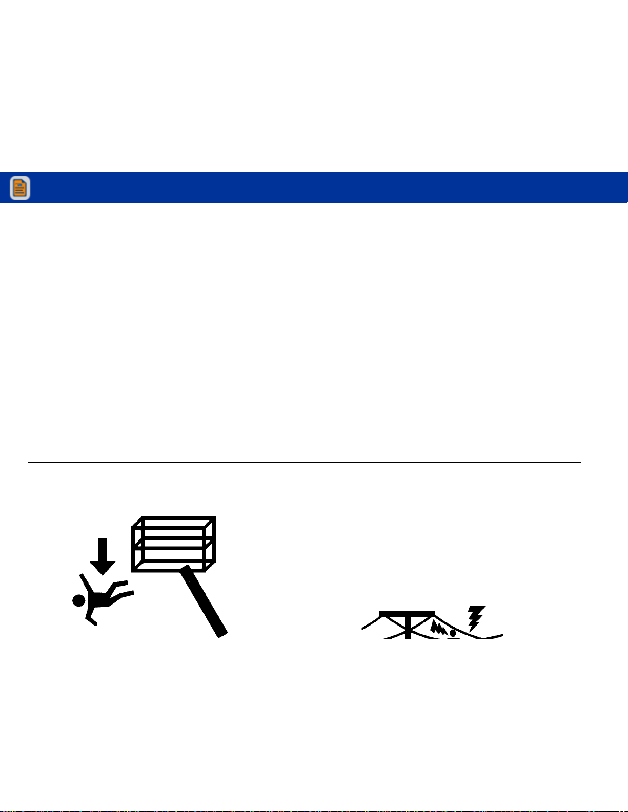
Trip and Fall Hazards
View thousands of Crane Specifications on FreeCraneSpecs.com
View thousands of Crane Specifications on FreeCraneSpecs.com
Page 14
SECTION 1 - SAFETY PRECAUTIONS
• Before operating the machine, make sure all gates are
closed and fastened in their proper position.
• Use extreme caution when entering or leaving platform.
Be sure that the boom is fully lowered. It may be necessary to telescope out to position the platform closer to the
ground for entry/exit. Face the machine, maintain “three
point contact” with the machine, using two hands and one
foot or two feet and one hand during entry and exit.
Electrocution Hazards
• This machine is not insulated and does not provide protection from contact or proximity to electrical current.
View thousands of Crane Specifications on FreeCraneSpecs.com
View thousands of Crane Specifications on FreeCraneSpecs.com
Page 15
SECTION 1 - SAFETY PRECAUTIONS
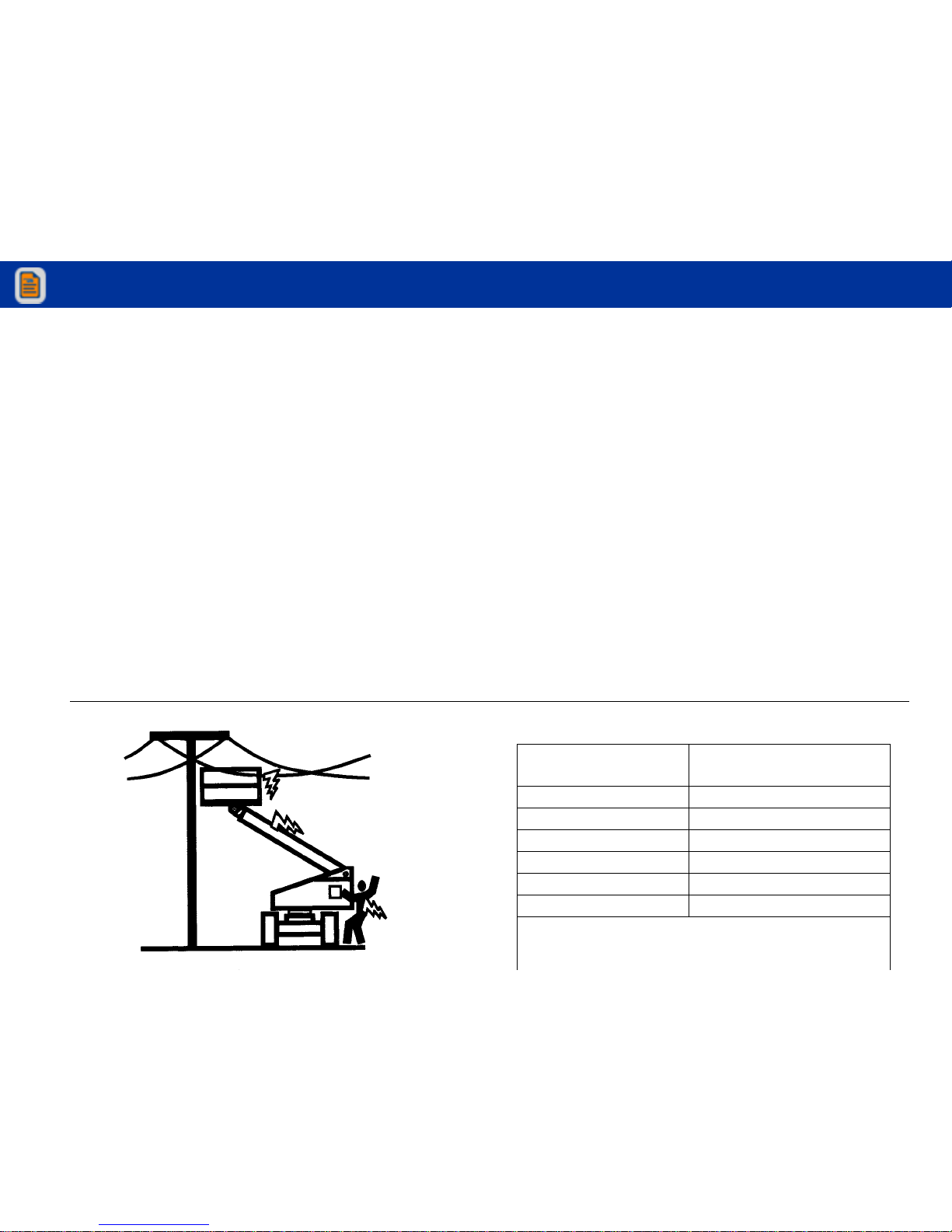
Table 1-1. Minimum Approach Distances (M.A.D.)
Voltage Range
(Phase to Phase)
MINIMUM APPROACH DISTANCE
in Feet (Meters)
0 to 50 KV 10 (3)
Over 50KV to 200 KV 15 (5)
Over 200 KV to 350 KV 20 (6)
Over 350 KV to 500 KV 25 (8)
Over 500 KV to 750 KV 35 (11)
Over 750 KV to 1000 KV 45 (14)
NOTE: This requirement shall apply except where
employer, local or governmental regulations
are more stringent.
View thousands of Crane Specifications on FreeCraneSpecs.com
View thousands of Crane Specifications on FreeCraneSpecs.com
Page 16
SECTION 1 - SAFETY PRECAUTIONS
• The minimum approach distance may be reduced if insulating barriers are installed to prevent contact, and the barriers
are rated for the voltage of the line being guarded. These
barriers shall not be part of (or attached to) the machine. The
minimum approach distance shall be reduced to a distance
within the designed working dimensions of the insulating
barrier. This determination shall be made by a qualified person in accordance with the employer, local, or governmental
requirements for work practices near energized equipment
DO NOT MANEUVER MACHINE OR PERSONNEL INSIDE PROHIBITED
ZONE (MAD). ASSUME ALL ELECTRICAL PARTS AND WIRING ARE
ENERGIZED UNLESS KNOWN OTHERWISE.
Tipping Hazards
• The user must be familiar with the surface before driving.
Do not exceed the allowable sideslope and grade while
driving.
View thousands of Crane Specifications on FreeCraneSpecs.com
View thousands of Crane Specifications on FreeCraneSpecs.com
Page 17

SECTION 1 - SAFETY PRECAUTIONS
• Do not elevate platform or drive with platform elevated
while on a sloping, uneven, or soft surface.
• Before driving on floors, bridges, trucks, and other surfaces, check allowable capacity of the surfaces.
• Never exceed the maximum platform capacity. Distribute
loads evenly on platform floor.
• Do not raise the platform or drive from an elevated position unless the machine is on firm, level and smooth surfaces.
• Keep the chassis of the machine at least 2 ft. (0.6m) from
holes, bumps, drop-offs, obstructions, debris, concealed
holes, and other potential hazards on the floor/surface.
• If boom assembly or platform is in a position that one or
more wheels are off the ground, all persons must be
removed before attempting to stabilize the machine. Use
cranes, forklift trucks, or other appropriate equipment to
stabilize machine.
Crushing and Collision Hazards
• Approved head gear must be worn by all operating and
ground personnel.
• Check work area for clearances overhead, on sides, and
bottom of platform when lifting or lowering platform, and
driving.
View thousands of Crane Specifications on FreeCraneSpecs.com
View thousands of Crane Specifications on FreeCraneSpecs.com
Page 18

SECTION 1 - SAFETY PRECAUTIONS
• Use the boom functions, not the drive function, to position
the platform close to obstacles.
• Always post a lookout when driving in areas where vision
is obstructed.
• Keep non-operating personnel at least 6 ft. (1.8m) away
from machine during all driving and swing operations.
• Limit travel speed according to conditions of ground surface, congestion, visibility, slope, location of personnel,
and other factors which may cause collision or injury to
personnel.
• Be aware of stopping distances in all drive speeds. When
driving in high speed, switch to low speed before stopping. Travel grades in low speed only.
1.4 TOWING, LIFTING, AND HAULING
• Never allow personnel in platform while towing, lifting, or
hauling.
• This machine should not be towed, except in the event of
emergency, malfunction, power failure, or loading/unloading. Refer to the Emergency Procedures section of this
manual for emergency towing procedures.
• Ensure boom is in the stowed position and the turntable
locked prior to towing, lifting or hauling. The platform must
be completely empty of tools.
• When lifting machine, lift only at designated areas of the
machine. Lift the unit with equipment of adequate capac-
View thousands of Crane Specifications on FreeCraneSpecs.com
View thousands of Crane Specifications on FreeCraneSpecs.com
Page 19

SECTION 1 - SAFETY PRECAUTIONS
1.5 ADDITIONAL HAZARDS / SAFETY
• Do not use machine as a ground for welding.
• When performing welding or metal cutting operations,
precautions must be taken to protect the chassis from
direct exposure to weld and metal cutting spatter.
• Do not refuel the machine with the engine running.
• Battery fluid is highly corrosive. Avoid contact with skin
and clothing at all times.
• Charge batteries only in a well ventilated area.
View thousands of Crane Specifications on FreeCraneSpecs.com
View thousands of Crane Specifications on FreeCraneSpecs.com
Page 20
SECTION 1 - SAFETY PRECAUTIONS
DO NOT OPERATE THE MACHINE WHEN WIND CONDITIONS EXCEED 28
MPH (12.5 M/S).
Table 1-2. Beaufort Scale (For Reference Only)
Beaufort
Number
Wind Speed
Description Land Conditions
mph m/s
0 0 0-0.2 Calm Calm. Smoke rises ver tically
1 1-3 0.3-1.5 Light air Wind motion visible in smoke
2 4-7 1.6-3.3 Light breeze Wind felt on exposed skin. Leav es rustle
3 8-12 3.4-5.4 Gentle breeze Leaves and smaller twigs in constant motion
View thousands of Crane Specifications on FreeCraneSpecs.com
View thousands of Crane Specifications on FreeCraneSpecs.com
Page 21

SECTION 2 - USER RESPONSIBILITIES, MACHINE PREPARATION, AND INSPECTION
SECTION 2. USER RESPONSIBILITIES, MACHINE PREPARATION, AND INSPECTION
2.1 PERSONNEL TRAINING
The aerial platform is a personnel handling device; so it is
necessary that it be operated and maintained only by trained
personnel.
Persons under the influence of drugs or alcohol or who are
subject to seizures, dizziness or loss of physical control must
not operate this machine.
Operator Training
Operator training must cover:
6. The safest means to operate the machine where overhead obstructions, other moving equipment, and obstacles, depressions, holes, dropoffs.
7. Means to avoid the hazards of unprotected electrical
conductors.
8. Specific job requirements or machine application.
Training Supervision
Training must be done under the supervision of a qualified
person in an open area free of obstructions until the trainee
has developed the ability to safely control and operate the
View thousands of Crane Specifications on FreeCraneSpecs.com
View thousands of Crane Specifications on FreeCraneSpecs.com
Page 22

SECTION 2 - USER RESPONSIBILITIES, MACHINE PREPARATION, AND INSPECTION
2.2 PREPARATION, INSPECTION, AND
MAINTENANCE
The following table covers the periodic machine inspections
and maintenance recommended by JLG Industries, Inc.
Consult local regulations for further requirements for aerial
work platforms. The frequency of inspections and maintenance must be increased as necessary when the machine is
used in a harsh or hostile environment, if the machine is
used with increased frequency, or if the machine is used in a
severe manner.
JLG INDUSTRIES, INC. RECOGNIZES A FACTORY-TRAINED SERVICE
TECHNICIAN AS A PERSON WHO HAS SUCCESSFULLY COMPLETED
THE JLG SERVICE TRAINING SCHOOL FOR THE SPECIFIC JLG PRODUCT
MODEL.
View thousands of Crane Specifications on FreeCraneSpecs.com
View thousands of Crane Specifications on FreeCraneSpecs.com
Page 23

SECTION 2 - USER RESPONSIBILITIES, MACHINE PREPARATION, AND INSPECTION
Table 2-1. Inspection and Maintenance Table
Type Frequen cy
Primary
Responsibility
Service
Qualification
Reference
Pre-Start Inspection Before using each day; or
whenever there’s an Operator change.
User or Operator User or Operator Operator and Safety Manual
Pre-Delivery Inspection
(See Note)
Before each sale, lease, or rental delivery. Owner, Dealer, or User Qualified JLG
Mechanic
Service and Maintenance
Manual and appli cable JLG
inspection form
Frequent Inspection
(See Note)
In service for 3 months or 150 hours, whichever
comes first; or
Out of service f or a period of more than 3 months;
Owner, Dealer, or User Qualified JLG
Mechanic
Service and Maintenance
Manual and appli cable JLG
inspection form
View thousands of Crane Specifications on FreeCraneSpecs.com
View thousands of Crane Specifications on FreeCraneSpecs.com
Page 24

SECTION 2 - USER RESPONSIBILITIES, MACHINE PREPARATION, AND INSPECTION
Pre-Start Inspection
The Pre-Start Inspection should include each of the following:
1. Cleanliness – Check all surfaces for leakage (oil, fuel,
or battery fluid) or foreign objects. Report any leakage to
the proper maintenance personnel.
2. Structure - Inspect the machine structure for dents,
damage, weld or parent metal cracks or other discrepancies.
(Domestic only) is enclosed in the weather resistant
storage container.
5. “Walk-Around” Inspection – Refer to Figure 2-4. thru
Figure 2-6.
6. Battery – Charge as required.
7. Fuel (Combustion Engine Powered Machines) – Add the
proper fuel as necessary.
8. Hydraulic Oil – Check the hydraulic oil level. Ensure
hydraulic oil is added as required.
9. Function Check – Once the “Walk-Around” Inspection
is complete, perform a functional check of all systems in
an area free of overhead and ground level obstructions.
View thousands of Crane Specifications on FreeCraneSpecs.com
View thousands of Crane Specifications on FreeCraneSpecs.com
Page 25

SECTION 2 - USER RESPONSIBILITIES, MACHINE PREPARATION, AND INSPECTION
Function Check
Perform the Function Check as follows:
1. From the ground control panel with no load in the platform:
a. Check that all guards protecting the switches or
locks are in place;
b. Operate all functions and check boom limit
switches; drive speed should switch to creep mode
if lower boom is elevated or main boom is above
horizontal.
c. Check auxiliary power (or manual descent);
d. Ensure that all machine functions are disabled
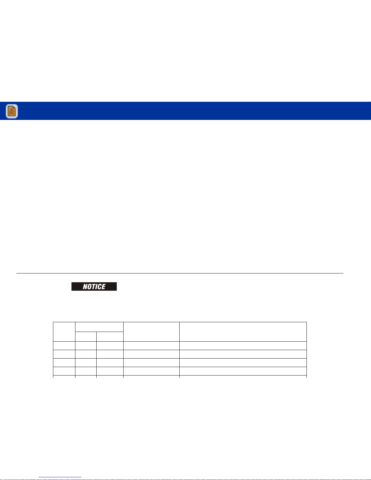
Cutout Description Market
Tilt
&
High
Drive
5 degree-reduces t he maximum speed of all boom
functions to creep whe n tilted and above elevation.
Reduces drive speed to creep when tilted. (See Figure 2-1.)
ANSI & Japan
3 degree-reduces t he maximum speed of all boom
functions to creep whe n tilted and above elevation.
Reduces drive speed to creep when tilted.(See Figure 2-1.)
CE & Australia
Drive Ba ttery Charger Cutout-cuts out drive when the bat-
tery charger is plugg ed in.
All
Battery Charger Cutout and Simultaneous Drive and
Boom Functions disabled above elevation. (See Fig-
CE & Australia
View thousands of Crane Specifications on FreeCraneSpecs.com
View thousands of Crane Specifications on FreeCraneSpecs.com
Page 26
SECTION 2 - USER RESPONSIBILITIES, MACHINE PREPARATION, AND INSPECTION
UPPER BOOM ANGLE TO BE 1° BELOW HORIZONTAL TO 3°
ABOVE HORIZONTAL TO ACTIVATE SWITCH. UPPER BOOM
ANGLE TO BE 1° TO 4° BELOW HORIZONTAL TO RESET SWITCH.
LOWER BOOM ANGLE TO BE 1° TO 5° ABOVE
HORIZONTAL TO ACTIVATE SWITCH. LOWER
B OO M A N GL E T O BE 0° T O 5 ° B E LOW
HORIZONTAL TO RESET SWITCH.
View thousands of Crane Specifications on FreeCraneSpecs.com
View thousands of Crane Specifications on FreeCraneSpecs.com
Page 27
SECTION 2 - USER RESPONSIBILITIES, MACHINE PREPARATION, AND INSPECTION
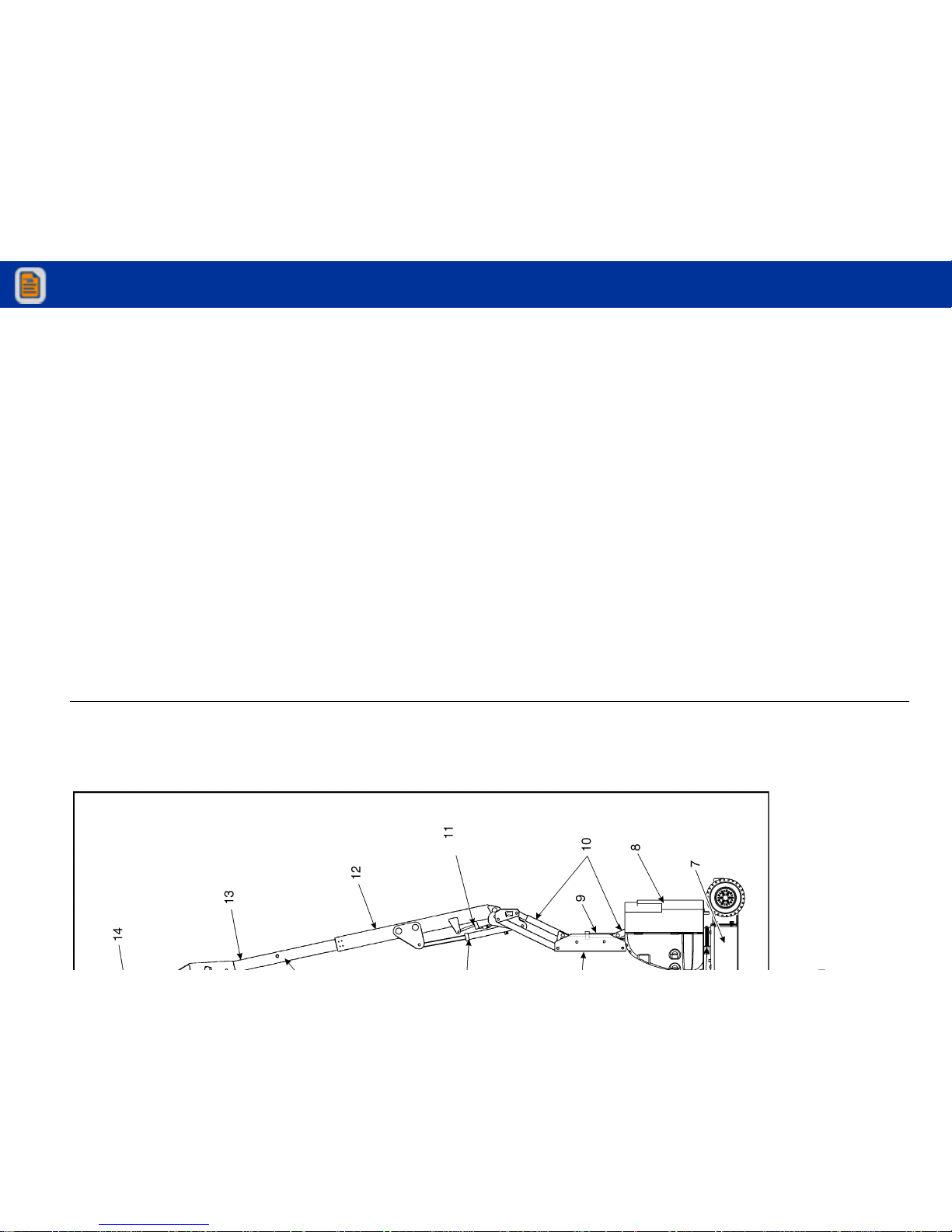
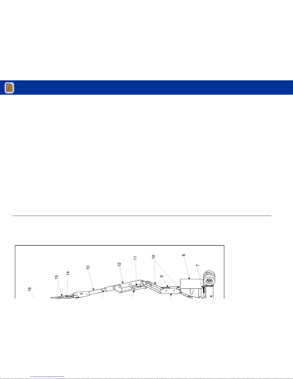
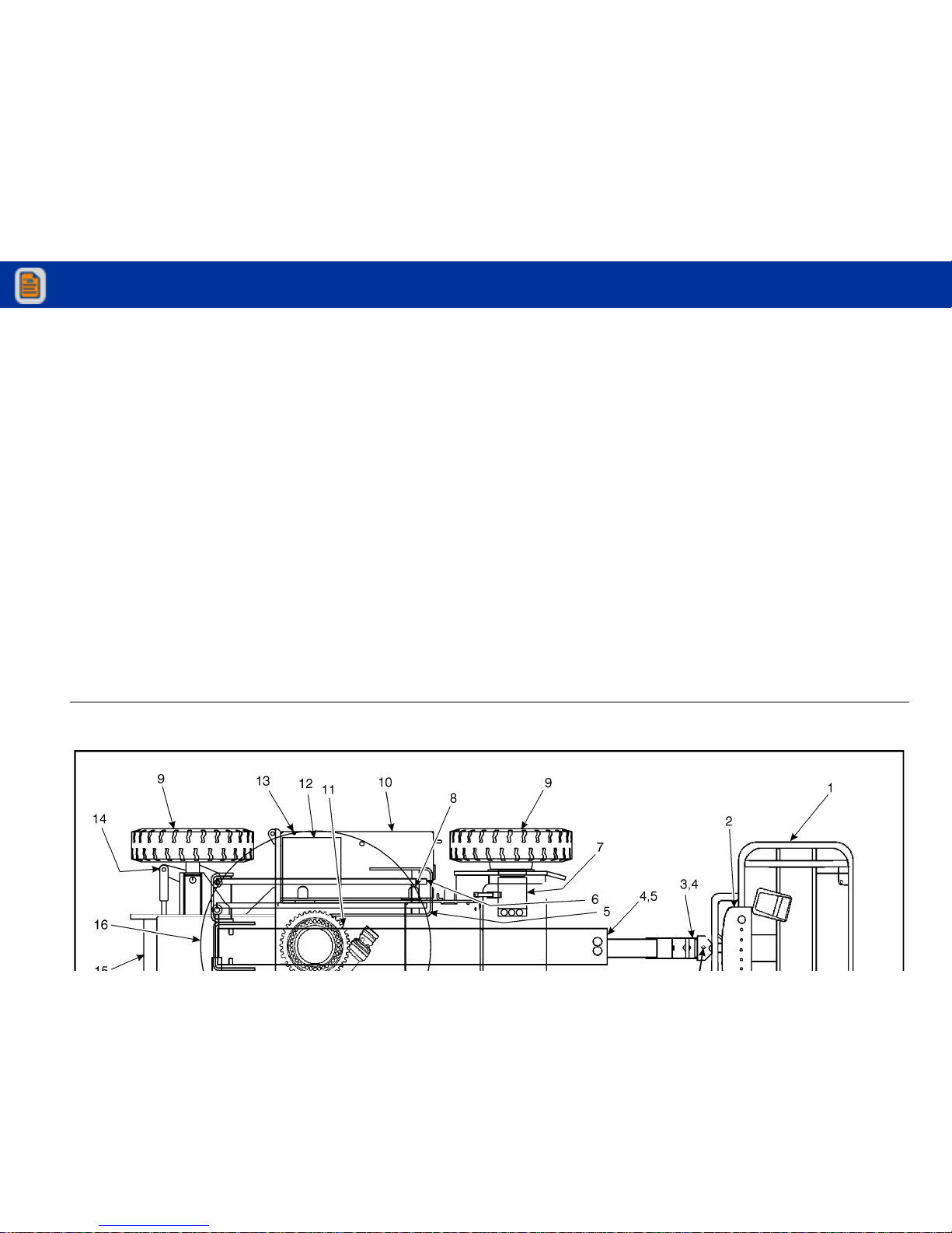
11. Master Cylinder
1 2. B a se B oo m
13. Fly Boom
1 4. P la t f or m Co n t ro l Bo x
View thousands of Crane Specifications on FreeCraneSpecs.com
View thousands of Crane Specifications on FreeCraneSpecs.com
Page 28
SECTION 2 - USER RESPONSIBILITIES, MACHINE PREPARATION, AND INSPECTION
12. Base Boom
13. Fly Boom
14. Jib Cylinder
15. Jib
16. Platfor m Control Box
View thousands of Crane Specifications on FreeCraneSpecs.com
View thousands of Crane Specifications on FreeCraneSpecs.com
Page 29
SECTION 2 - USER RESPONSIBILITIES, MACHINE PREPARATION, AND INSPECTION
View thousands of Crane Specifications on FreeCraneSpecs.com
View thousands of Crane Specifications on FreeCraneSpecs.com
Page 30

SECTION 2 - USER RESPONSIBILITIES, MACHINE PREPARATION, AND INSPECTION
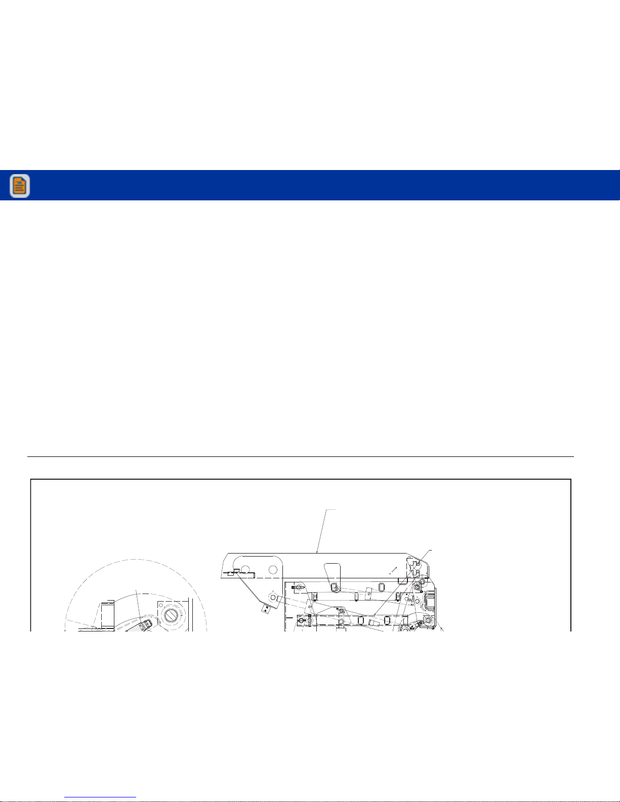
GENERAL
Begin the "Walk-Around Inspection" at Item 1, as noted on
the diagram. Continue to the right (counterclockwise
viewed from top) checking each item in sequence for the
conditions listed in the following checklist.
TO AVOID POSSIBLE INJURY, BE SURE MACHINE POWER IS OFF.
DO NOT OPERATE MACHINE UNTIL ALL MALFUNCTIONS HAVE BEEN
CORRECTED.
3. Fly Boom Nose and Platform Support - Ensure fly
boom nose and platform support are free of debris,
obstructions, etc.
4. All Hydraulic Cylinders - No visible damage; pivot
pins and hydraulic hoses undamaged, not leaking.
5. Slave Cylinder - No visible damage; pivot pins secure;
hydraulic hoses undamaged, not leaking.
6. Boom Sections/Uprights/Turntable - See Inspection
Note.
7. Limit Switches - Switches operable; See Inspection
Note.
View thousands of Crane Specifications on FreeCraneSpecs.com
View thousands of Crane Specifications on FreeCraneSpecs.com
Page 31

SECTION 2 - USER RESPONSIBILITIES, MACHINE PREPARATION, AND INSPECTION
12. Hydraulic Pump and Reservoir - See Inspection
Note. Recommended hydraulic fluid level on sight
gage (system shut down, boom in stowed position).
Breather cap secure and working.
13. Cowling and Latches - All cowling, doors and latches
in working condition; See Inspection Note.
14. Tie Rod Ends and Steering Spindles - See Inspection
Note. Tie rod end stubs locked.
15. Frame - See Inspection Note. No evidence of cables
dragging under the machine.
16. Counterweight - See Inspection Note.
17. Swing Motor and Worm Gear - See Inspection Note;
evidence of proper lubrication.
18. Battery Charger - See Inspection Note.
19. Control Valve - See Inspection Note.
20. Manual Descent Valve - See Inspection Note.
21. Jib (E300 AJ only) - See Inspection Note.
Figure 2-6. Daily Walk-Around Inspection - Sheet 3 of 3
View thousands of Crane Specifications on FreeCraneSpecs.com
View thousands of Crane Specifications on FreeCraneSpecs.com
Page 32

SECTION 2 - USER RESPONSIBILITIES, MACHINE PREPARATION, AND INSPECTION
NOTES:
View thousands of Crane Specifications on FreeCraneSpecs.com
View thousands of Crane Specifications on FreeCraneSpecs.com
Page 33

SECTION 3 - MACHINE CONTROLS AND INDICATORS
SECTION 3. MACHINE CONTROLS AND INDICATORS
3.1 GENERAL
THE MANUFACTURER HAS NO DIRECT CONTROL OVER MACHINE
APPLICATION AND OPERATION. THE USER AND OPERATOR ARE
RESPONSIBLE FOR CONFORMING WITH GOOD SAFETY PRACTICES.
This section provides the necessary information needed to
understand control functions.
3.2 CONTROLS AND INDICATORS
Ground Control Station
See Figure 3-1., Figure 3-2., and Figure 3-3.
NOTE: When machine is shut down the Platform/Ground Select
switch and Emergency Stop must be positioned to OFF.
NOTE: When Power/Emergency Stop Switch is in the on position
and motor is not running, an alarm will sound, indicating
power is on.
NOTE: If equipped, the Function Enable switch must be held
View thousands of Crane Specifications on FreeCraneSpecs.com
View thousands of Crane Specifications on FreeCraneSpecs.com
Page 34

SECTION 3 - MACHINE CONTROLS AND INDICATORS
1. Battery Status
2. Not Used
3. Telescope
4. Main Lift
5. Lower Lift
6. Swing
7. Platform Rotate
View thousands of Crane Specifications on FreeCraneSpecs.com
View thousands of Crane Specifications on FreeCraneSpecs.com
Page 35

SECTION 3 - MACHINE CONTROLS AND INDICATORS
1. Battery Status
2. Not Used
3. Telescope
4. Main Lift
5. Lower Lift
6. Swing
7. Platform Rotate
View thousands of Crane Specifications on FreeCraneSpecs.com
View thousands of Crane Specifications on FreeCraneSpecs.com
Page 36

SECTION 3 - MACHINE CONTROLS AND INDICATORS
1. Battery Status
2. Jib Swing
3. Telescope
4. Main Lift
5. Lower Lift
6. Swing
7. Platform Rotate
8. Platform Level
View thousands of Crane Specifications on FreeCraneSpecs.com
View thousands of Crane Specifications on FreeCraneSpecs.com
Page 37

SECTION 3 - MACHINE CONTROLS AND INDICATORS
3. Te le s co p e
Provides extension and retraction of the main boom.
NOTE: Main Lift, Swing, Platform Level, Main Telescope, Lower
Lift and Platform Rotator control switches are springloaded and will automatically return to neutral (off) when
released.
4. Main Lift
Provides raising/lowering of the main boom when positioning up or down.
5. Lower Lift
7. Platform Rotate
Permits rotation of the platform when positioned to the
right or left.
ONLY USE THE PLATFORM LEVELING OVERRIDE FUNCTION FOR
SLIGHT LEVELING OF THE PLATFORM. INCORRECT USE COULD CAUSE
THE LOAD/OCCUPANTS TO SHIFT OR FALL. FAILURE TO DO SO COULD
RESULT IN DEATH OR SERIOUS INJURY.
8. Platform leveling Override
Allows the operator to compensate for any difference in
View thousands of Crane Specifications on FreeCraneSpecs.com
View thousands of Crane Specifications on FreeCraneSpecs.com
Page 38

SECTION 3 - MACHINE CONTROLS AND INDICATORS
WHEN THE MACHINE IS SHUT DOWN THE MASTER/EMERGENCY STOP
SWITCH MUST BE POSITIONED TO THE OFF POSITION TO PREVENT
DRAINING THE BATTERIES.
10. Power/Emergency Stop Switch.
A two-position red mushroom shaped switch furnishes
power to PLATFORM/GROUND SELECT switch when
pulled out (on). When pushed in (off), power is shut off
to the PLATFORM/GROUND SELECT switch.
11. Battery Indicator and Hourmeter
12. Control Station Selector
Supplies power to the platform control console when
positioned to the PLATFORM. With the switch in
GROUND position, power is shut off to the platform control console, and only the controls on the ground control
panel are operable.
NOTE: When the Platform/Ground Select Switch is in the center
position, power is shut off to the controls at both operating stations. Remove the key to prevent the controls from
being actuated. The key is removable in the platform position on CE machines. The key must be available to ground
personnel in the event of an emergency.
View thousands of Crane Specifications on FreeCraneSpecs.com
View thousands of Crane Specifications on FreeCraneSpecs.com
Page 39

SECTION 3 - MACHINE CONTROLS AND INDICATORS
Platform Control Station
See Figure 3-4.
1. Posi-Track
When one wheel is slipping and the machine is not
descending a grade, automatic traction control will provide added torque to both wheels. While this function is
automatic, it may also be manually engaged by moving
the toggle switch to the forward position. Positrac will be
engaged for approximately 20 seconds.
3. Horn
A push-type HORN switch supplies electrical power to
an audible warning device when pressed.
4. Power/Emergency Stop
A two-position red mushroom shaped switch furnishes
power to PLATFORM Controls when pulled out (on).
When pushed in (off), power is shut off to the platform
functions.
5. Lights (If Equipped)
This switch operates control console panel lights and
View thousands of Crane Specifications on FreeCraneSpecs.com
View thousands of Crane Specifications on FreeCraneSpecs.com
Page 40

SECTION 3 - MACHINE CONTROLS AND INDICATORS
View thousands of Crane Specifications on FreeCraneSpecs.com
View thousands of Crane Specifications on FreeCraneSpecs.com
Page 41

SECTION 3 - MACHINE CONTROLS AND INDICATORS
NOTE: Main Lift, Swing, and Drive control levers are spring
loaded and will automatically return to neutral (off) position when released.
6. Drive/Steer
Push forward to drive forward, pull back to drive in
reverse. Steering is accomplished via a thumb-activated
rocker switch on the end of the steer handle.
NOTE: When boom is positioned above horizontal and Posi-Track
or Function speed are positioned to high, high function
speeds are automatically cut out and the machine continues to operate at a lower speed.
10. Lower Lift
Provides for raising and lowering of Upright when positioned to UP or DOWN.
11. Platform Rotate
Permits rotation of the platform when positioned to the
right or left.
12. Function Speed Control
Adjusts speed of Boom and Swing Functions. Rotate
CCW for slower speed and CW for faster speed. To
adjust Drive, Swing, and Main Lift to creep, turn knob
View thousands of Crane Specifications on FreeCraneSpecs.com
View thousands of Crane Specifications on FreeCraneSpecs.com
Page 42

SECTION 3 - MACHINE CONTROLS AND INDICATORS
Table 3-1.Simultaneous Functions
If This Function is Selected: These Functions Will Also Work at the Same Time:
Drive and Steer
Swing* Lower Lift** Main Lift** Telescope
Swing Drive and Steer
Lower Lift** Main Lift** Telescope
Lower Lift Drive and Steer Swing*
No Telescope
Main Lift Drive and Steer Swing* No Te le s co p e
Telescope Drive and Steer Swing* Lower Lif t** Main Lift**
Jib Articulate Drive and Steer Swing* Lower Lift** Main Lift** Telescope
View thousands of Crane Specifications on FreeCraneSpecs.com
View thousands of Crane Specifications on FreeCraneSpecs.com
Page 43

SECTION 3 - MACHINE CONTROLS AND INDICATORS
Platform Control Indicator Panel
NOTE: The platform control indicator panel uses different shaped
symbols to alert the operator to different types of operational situations that could arise. The meaning of those
symbols are explained below.
1. Tilt Alarm Warning Light and Alarm
This orange illuminator indicates that the chassis is on a
slope. An alarm will also sound when the chassis is on a
slope and the boom is above horizontal. If lit when boom
is raised or extended, retract and lower to below horizontal then reposition machine so that it is level before
continuing operation. If the boom is above horizontal
and the machine is on a slope, the tilt alarm warning
Indicates a potentially hazardous situation, which
if not corrected, could result in serious injury or
death. This indicator will be red.
Indicates an abnormal operating condition,
which if not corrected, may result in machine
interruption or damage. This indicator will be yellow.
Tilt Angle Market
3° CE & Australia
5° ANSI & Japan
View thousands of Crane Specifications on FreeCraneSpecs.com
View thousands of Crane Specifications on FreeCraneSpecs.com
Page 44

SECTION 3 - MACHINE CONTROLS AND INDICATORS
The four likely causes of a system fault are:
a. The seven second enable time has been allowed to
lapse or a function was selected before depressing
the footswitch. The system reads this condition as a
fault, just as it would if the footswitch were jammed
in the depressed position or a function switch were
stuck in the on position. Re-depress the footswitch
to power the controls and extinguish the light.
b. The maximum power limit has been reached and
the machine is not moving. This could happen
when the machine is stuck or when attempting to
travel over rough terrain or on steep grades which
exceed the rated gradeability of the machine. This
1704239 E
+-
76
1
5
4
3
2
1. Tilt
5. Enable
View thousands of Crane Specifications on FreeCraneSpecs.com
View thousands of Crane Specifications on FreeCraneSpecs.com
Page 45

SECTION 3 - MACHINE CONTROLS AND INDICATORS
4. Posi-Track Indicator
This indicator lights to show that posi-traction is operating.
5. Enable Indicator/Footswitch
To operate any function, the footswitch must be
depressed and the function selected within seven seconds. The enable indicator shows that the controls are
enabled. If a function is not selected within seven seconds, or if a seven second lapse between ending one
function and beginning the next function, the enable
light will go out and the footswitch must be released and
depressed again to enable the controls.
FOOTSWITCH MUST BE ADJUSTED IF FUNCTIONS ACTIVATE WHEN
SWITCH ONLY OPERATES WITHIN LAST 1/4" OF TRAVEL, TOP OR BOTTOM.
6. Low Battery Indicator
Indicates the batteries are low and need to be charged.
7. Creep Speed Indicator
When the Function Speed Control is turned to the creep
position, the indicator acts as a reminder that all functions are set to the slowest speed.
View thousands of Crane Specifications on FreeCraneSpecs.com
View thousands of Crane Specifications on FreeCraneSpecs.com
Page 46

SECTION 3 - MACHINE CONTROLS AND INDICATORS
NOTES:
View thousands of Crane Specifications on FreeCraneSpecs.com
View thousands of Crane Specifications on FreeCraneSpecs.com
Page 47

SECTION 4 - MACHINE OPERATION
SECTION 4. MACHINE OPERATION
4.1 DESCRIPTION
This machine is a self-propelled hydraulic lift equipped with a
work platform on the end of an elevating, articulating and
rotating boom.
The primary operator control station is in the platform. From
this control station, the operator can drive and steer the
machine in both forward and reverse directions. The operator can raise or lower the boom or swing the boom to the left
or right. Standard boom swing is 360 degree non-continuous
left and right of the stowed position. The machine has a
Ground Control Station which will override the Platform Con-
4.2 OPERATING CHARACTERISTICS AND
LIMITATIONS
Capacities
Raising boom above horizontal with or without any load in
platform, is based on the following criteria:
1. Machine is positioned on a smooth, firm and level surface.
2. Load is within manufacturers rated design capacity.
View thousands of Crane Specifications on FreeCraneSpecs.com
View thousands of Crane Specifications on FreeCraneSpecs.com
Page 48

SECTION 4 - MACHINE OPERATION
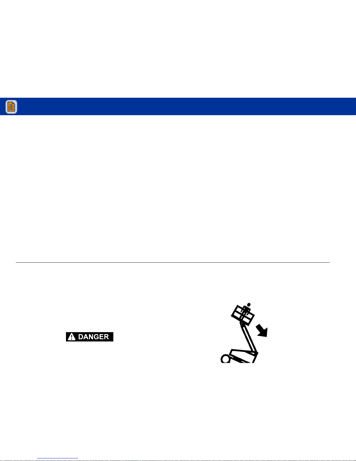
Stability
Machine stability is based on two (2) conditions which are
called FORWARD stability and BACKWARD stability. The
machine’s position of least FORWARD stability is shown in
Figure 4-1. and its position of least BACKWARD stability is
shown in Figure 4-2.
TO AVOID FORWARD OR BACKWARD UPSET, DO NOT OVERLOAD
MACHINE, OR OPERATE ON OUT-OF-LEVEL SURFACE.
4.3 MOTOR OPERATION
Power/Emergency Stop
This red, mushroom-shaped switch provides battery power
to the Platform/Ground Select switch, when pulled out (on),
for all machine functions. The switch should be pushed in
(off) when recharging the batteries or parking the machine
overnight.
Platform/Ground Select Switch
The Platform/Ground Select switch functions to direct battery
power to the desired control station when the POWER/
View thousands of Crane Specifications on FreeCraneSpecs.com
View thousands of Crane Specifications on FreeCraneSpecs.com
Page 49

SECTION 4 - MACHINE OPERATION
LOW ER AR MS
FULLY ELEVATED
MAIN BOOM
HORIZONTAL
MAIN BOOM
FULLY EXTENDED
MACHINE WILL " TIP OVER" IN THIS
DIRECTION IF OVERLOADED OR
View thousands of Crane Specifications on FreeCraneSpecs.com
View thousands of Crane Specifications on FreeCraneSpecs.com
Page 50

SECTION 4 - MACHINE OPERATION
PLATFORM ROTATED
90 DEGREES
(NOT SHOWN ROTATED)
MAIN BOOM FUL LY ELEVATED
AND FULLY RETRACTED
MACHINE WILL " TIP OVER" IN THIS
DIRECTION IF OVERLOADED OR
OPERATED ON AN
OUT-OF-LEVEL SURFACE
View thousands of Crane Specifications on FreeCraneSpecs.com
View thousands of Crane Specifications on FreeCraneSpecs.com
Page 51

SECTION 4 - MACHINE OPERATION
Motor Activation
FOOTSWITCH MUST BE DEPRESSED PRIOR TO ACTIVATING ANY FUNCTION, OTHERWISE FUNCTION WILL NOT OPERATE.
The motor becomes activated and operates the desired
function when the Emergency Stop switch is pulled out (on),
the Platform/Ground select switch is in the appropriate position and the Footswitch is depressed.
IF A MOTOR MALFUNCTION NECESSITATES UNSCHEDULED SHUT-
4.4 TRAVELING (DRIVING)
IF THE MACHINE IS OPERATED AT A VERY SLOW SPEED OR STALLED
WHEN CLIMBING A GRADE OF 20% OR GREATER, DRIVE FUNCTION
WILL STOP. REMOVE FOOT FROM FOOT-SWITCH, AND DEPRESS FOOTSWITCH TO RESET.
DO NOT DRIVE WITH BOOM ABOVE HORIZONTAL EXCEPT ON A
SMOOTH, FIRM AND LEVEL SURFACE.
DO NOT DRIVE ON SIDE SLOPES EXCEEDING 5 DEGREES
View thousands of Crane Specifications on FreeCraneSpecs.com
View thousands of Crane Specifications on FreeCraneSpecs.com
Page 52

SECTION 4 - MACHINE OPERATION
BEFORE DRIVING, MAKE SURE BOOM IS POSITIONED OVER REAR
DRIVE AXLE. IF BOOM IS OVER STEER WHEELS, STEER AND DRIVE
CONTROLS WILL MOVE IN OPPOSITE DIRECTIONS TO MACHINE
MOTION.
Traveling Forward and Reverse
FOOTSWITCH MUST BE DEPRESSED PRIOR TO ACTIVATING ANY FUNCTION, OTHERWISE FUNCTION WILL NOT OPERATE.
4.5 STEERING
Depress footswitch to steer machine, position thumb switch
on Drive/Steer controller to RIGHT for steering right, or to
LEFT for steering left.
4.6 PLATFORM
Loading From Ground Level
1. Position chassis on a smooth, firm and level surface.
2. If total load (personnel, tools and supplies) is 500 LB.
(227 kg) or less, distribute load uniformly on platform
floor and proceed to work position.
View thousands of Crane Specifications on FreeCraneSpecs.com
View thousands of Crane Specifications on FreeCraneSpecs.com
Page 53

SECTION 4 - MACHINE OPERATION
NOTE: Machine shown in transport position. For
machines provided with jib (models
E300AJ and E300AJP) the position of the
jib doesn't affect the transport position
View thousands of Crane Specifications on FreeCraneSpecs.com
View thousands of Crane Specifications on FreeCraneSpecs.com
Page 54

SECTION 4 - MACHINE OPERATION
Platform Level Adjustment
ONLY USE THE PLATFORM LEVELING OVERRIDE FUNCTION FOR
SLIGHT LEVELING OF THE PLATFORM. INCORRECT USE COULD CAUSE
THE LOAD/OCCUPANTS TO SHIFT OR FALL. FAILURE TO DO SO COULD
RESULT IN DEATH OR SERIOUS INJURY.
1. Leveling UP. Depress footswitch to raise platform, position PLATFORM/LEVEL control switch UP and hold until
platform is level.
2. Leveling DOWN. Depress footswitch to lower platform,
4.7 BOOM
A RED TILT WARNING LIGHT IS LOCATED ON THE CONTROL CONSOLE
WHICH LIGHTS WHEN THE CHASSIS IS ON A 5 DEGREE OR GREATER
SLOPE. DO NOT SWING OR RAISE BOOM ABOVE HORIZONTAL WHEN
LIGHT IS LIT.
DO NOT DEPEND ON TILT ALARM AS A LEVEL INDICATOR FOR THE
CHASSIS. TILT ALARM INDICATES CHASSIS IS ON A SEVERE SLOPE (5
DEGREE OR GREATER). CHASSIS MUST BE LEVEL BEFORE SWINGING,
OR RAISING BOOM ABOVE HORIZONTAL.
View thousands of Crane Specifications on FreeCraneSpecs.com
View thousands of Crane Specifications on FreeCraneSpecs.com
Page 55

SECTION 4 - MACHINE OPERATION
TO AVOID SERIOUS INJURY, DO NOT OPERATE MACHINERY IF ANY
CONTROL LEVER OR TOGGLE SWITCH CONTROLLING PLATFORM
MOVEMENT DOES NOT RETURN TO THE ‘OFF’ OR NEUTRAL POSITION
WHEN RELEASED.
TO AVOID A COLLISION AND INJURY IF PLATFORM DOES NOT STOP
WHEN A CONTROL SWITCH OR LEVER IS RELEASED, REMOVE FOOT
FROM FOOTSWITCH OR USE EMERGENCY STOP SWITCH TO STOP THE
MACHINE.
Swinging the Boom
Raising and Lowering the Upper Boom
Depress footswitch to raise or lower the Upper Boom, with footswitch activated, position Upper Boom Lift switch to UP or
DOWN until desired height is reached.
4.8 BOOM FUNCTION SPEEDS
The Function Speed Control affects the speed of boom functions LIFT, TELESCOPE, and SWING. Turn the control CW to
increase function speed or CCW to decrease function speed.
View thousands of Crane Specifications on FreeCraneSpecs.com
View thousands of Crane Specifications on FreeCraneSpecs.com
Page 56

SECTION 4 - MACHINE OPERATION
4.9 SHUT DOWN AND PARK
NOTE: When parking battery powered units overnight, batteries
should be charged in accordance with instructions in
Section 6 to ensure readiness for following workday.
NOTE: Electric machines are equipped with a static strap due to
static electricity build-ups. Strap is located under rear of
machine chassis.
To shut down and park the machine, the procedures are as
follows:
1. Drive machine to a reasonably well protected area.
4.10 LIFTING AND TIE DOWN
Lifting
1. Refer to the Serial Number Tag, call JLG Industries, or
weigh the individual unit to find out the Gross Vehicle
Weight.
2. Place the boom in the stowed position.
3. Remove all loose items from the machine.
4. Properly adjust the rigging to prevent damage to the
machine and so the machine remains level.
View thousands of Crane Specifications on FreeCraneSpecs.com
View thousands of Crane Specifications on FreeCraneSpecs.com
Page 57

SECTION 4 - MACHINE OPERATION
View thousands of Crane Specifications on FreeCraneSpecs.com
View thousands of Crane Specifications on FreeCraneSpecs.com
Page 58

SECTION 4 - MACHINE OPERATION
View thousands of Crane Specifications on FreeCraneSpecs.com
View thousands of Crane Specifications on FreeCraneSpecs.com
Page 59

SECTION 4 - MACHINE OPERATION
View thousands of Crane Specifications on FreeCraneSpecs.com
View thousands of Crane Specifications on FreeCraneSpecs.com
Page 60

SECTION 4 - MACHINE OPERATION
View thousands of Crane Specifications on FreeCraneSpecs.com
View thousands of Crane Specifications on FreeCraneSpecs.com
Page 61

SECTION 4 - MACHINE OPERATION
View thousands of Crane Specifications on FreeCraneSpecs.com
View thousands of Crane Specifications on FreeCraneSpecs.com
Page 62

SECTION 4 - MACHINE OPERATION
Table 4-1. E300A Decal Legend - Part 1 of 2
Item # ANSI
0259007-9
Australian
0259009-4
CE
English
0259314-5
German
0259013-5
Dutch
0259015-5
Italian
0259017-5
French
0259019-5
Spanish
0259021-5
1 1703797 1703992 1703806 1703799 1703913 1703915 1703917 1703919
2 1703798 1703807 1703807 1703800 1703914 1703916 1703918 1703920
3 1703805 - - - - - - - - - - - - - -
4 1703804 1701518 1701518 1701518 1701518 1701518 1701518 1701518
5 1704253 - - - - - - - - - - - - - -
View thousands of Crane Specifications on FreeCraneSpecs.com
View thousands of Crane Specifications on FreeCraneSpecs.com
Page 63

SECTION 4 - MACHINE OPERATION
14 1702688 - - - - - - - - - - - - - -
15 - -- - - -- -- -- - - -- -
16 1701502 1701502 1701502 1701502 1701502 1701502 1701502 1701502
17 1701503 1701503 1701503 1701503 1701503 1701503 1701503 1701503
18 1701504 1701504 1701504 1701504 1701504 1701504 1701504 1701504
19 1702153 - - - - - - - - - - - - - -
Table 4-1. E300A Decal Legend - Part 1 of 2
Item # ANSI
0259007-9
Australian
0259009-4
CE
English
0259314-5
German
0259013-5
Dutch
0259015-5
Italian
0259017-5
French
0259019-5
Spanish
0259021-5
View thousands of Crane Specifications on FreeCraneSpecs.com
View thousands of Crane Specifications on FreeCraneSpecs.com
Page 64

SECTION 4 - MACHINE OPERATION
28 - -- - - -- -- -- - - -- -
29 - -- - - -- -- -- - - -- -
30 - -- - - -- -- -- - - -- -
31 - -- - - -- -- -- - - -- -
32 - -- - - -- -- -- - - -- -
33 - -- - - -- -- -- - - -- -
Table 4-1. E300A Decal Legend - Part 1 of 2
Item # ANSI
0259007-9
Australian
0259009-4
CE
English
0259314-5
German
0259013-5
Dutch
0259015-5
Italian
0259017-5
French
0259019-5
Spanish
0259021-5
View thousands of Crane Specifications on FreeCraneSpecs.com
View thousands of Crane Specifications on FreeCraneSpecs.com
Page 65

SECTION 4 - MACHINE OPERATION
42 - -- - - -- -- -- - - -- -
43 1702901 1702901 1702901 1702901 1702901 1702901 1702901 1702901
44 1704412 1704412 1704412 1704412 1704412 1704412 1704412 1704412
Table 4-1. E300A Decal Legend - Part 1 of 2
Item # ANSI
0259007-9
Australian
0259009-4
CE
English
0259314-5
German
0259013-5
Dutch
0259015-5
Italian
0259017-5
French
0259019-5
Spanish
0259021-5
View thousands of Crane Specifications on FreeCraneSpecs.com
View thousands of Crane Specifications on FreeCraneSpecs.com
Page 66

SECTION 4 - MACHINE OPERATION
Table 4-2. E300A Decal Legend - Part 2 of 2
Item # Japanese
0259023-4
Korean
0259025-5
ANSI
English/
Spanish
0259027-5
ANSI
Chinese/
English
0259031-5
ANSI
Portuguese/
Spanish
0259035-6
Norwegian
0273209-2
1 1703926 1703927 1703923 1703925 1703928 1705254
2 1703932 1703933 1703929 1703931 1703934 1705255
3 1703938 1703939 1703935 1703937 1703940 - -
4 1703950 1703951 1703947 1703949 1703952 1701518
View thousands of Crane Specifications on FreeCraneSpecs.com
View thousands of Crane Specifications on FreeCraneSpecs.com
Page 67

SECTION 4 - MACHINE OPERATION
14 - - - - 1702688 - - - - - -
15 - - - - - - - - - - - -
16 1701502 1701502 1701502 1701502 1701502 1701502
17 1701503 1701503 1701503 1701503 1701503 1701503
18 1701504 1701504 1701504 1701504 1701504 1701504
Table 4-2. E300A Decal Legend - Part 2 of 2
Item # Japanese
0259023-4
Korean
0259025-5
ANSI
English/
Spanish
0259027-5
ANSI
Chinese/
English
0259031-5
ANSI
Portuguese/
Spanish
0259035-6
Norwegian
0273209-2
View thousands of Crane Specifications on FreeCraneSpecs.com
View thousands of Crane Specifications on FreeCraneSpecs.com
Page 68

SECTION 4 - MACHINE OPERATION
28 - - - - - - - - - - - -
29 - - - - - - - - - - - -
30 - - - - - - - - - - - -
31 - - - - - - - - - - - -
32 - - - - - - - - - - - -
Table 4-2. E300A Decal Legend - Part 2 of 2
Item # Japanese
0259023-4
Korean
0259025-5
ANSI
English/
Spanish
0259027-5
ANSI
Chinese/
English
0259031-5
ANSI
Portuguese/
Spanish
0259035-6
Norwegian
0273209-2
View thousands of Crane Specifications on FreeCraneSpecs.com
View thousands of Crane Specifications on FreeCraneSpecs.com
Page 69

SECTION 4 - MACHINE OPERATION
42 - - - - - - - - - - - -
43 1702901 1702901 1702901 1702901 1702901 1705246
44 1704412 1704412 1704412 1704412 1704412 1704412
Table 4-2. E300A Decal Legend - Part 2 of 2
Item # Japanese
0259023-4
Korean
0259025-5
ANSI
English/
Spanish
0259027-5
ANSI
Chinese/
English
0259031-5
ANSI
Portuguese/
Spanish
0259035-6
Norwegian
0273209-2
View thousands of Crane Specifications on FreeCraneSpecs.com
View thousands of Crane Specifications on FreeCraneSpecs.com
Page 70

SECTION 4 - MACHINE OPERATION
Table 4-3. E300AJ Decal Legend
Item # ANSI
0259008-7
CE/Aus
0275064-3
Japanese
0259024-5
Korean
0259026-6
Spanish
0259028-6
French
0259030-6
Chinese
0259032-6
Portuguese/
Spanish
0259036-6
1 1703797 1705921 1703926 1703927 1703923 1703924 1703925 1703928
2 1703798 1705822 1703932 1703933 1703929 1703930 1703931 1703934
3 1703805 - - 1703938 1703939 1703935 1703936 1703937 17 03940
4 1703804 1701518 1703950 1703951 1703947 1703948 1703949 1703952
5 1704253 - - - - - - 1704253 1704253 - - - -
View thousands of Crane Specifications on FreeCraneSpecs.com
View thousands of Crane Specifications on FreeCraneSpecs.com
Page 71

SECTION 4 - MACHINE OPERATION
14 1707013 - - - - - - 1707013 1 707047 - - 1707013
15 - - - - - - - - - - - - - - - -
16 1701502 1701502 1701502 1701502 1701502 1701502 1701502 1701502
17 1701503 1701503 1701503 1701503 1701503 1701503 1701503 1701503
18 1701504 1701504 1701504 1701504 1701504 1701504 1701504 1701504
19 1702153 - - - - - - 1704007 1 704006 - - 1704008
Table 4-3. E300AJ Decal Legend
Item # ANSI
0259008-7
CE/Aus
0275064-3
Japanese
0259024-5
Korean
0259026-6
Spanish
0259028-6
French
0259030-6
Chinese
0259032-6
Portuguese/
Spanish
0259036-6
View thousands of Crane Specifications on FreeCraneSpecs.com
View thousands of Crane Specifications on FreeCraneSpecs.com
Page 72

SECTION 4 - MACHINE OPERATION
28 - - - - - - - - - - - - - - - -
29 - - - - - - - - - - - - - - - -
30 - - - - - - - - - - - - - - - -
31 - - - - - - - - - - - - - - - -
32 - - - - - - - - - - - - - - - -
33 - - - - - - - - - - - - - - - -
Table 4-3. E300AJ Decal Legend
Item # ANSI
0259008-7
CE/Aus
0275064-3
Japanese
0259024-5
Korean
0259026-6
Spanish
0259028-6
French
0259030-6
Chinese
0259032-6
Portuguese/
Spanish
0259036-6
View thousands of Crane Specifications on FreeCraneSpecs.com
View thousands of Crane Specifications on FreeCraneSpecs.com
Page 73

SECTION 4 - MACHINE OPERATION
42 - - - - - - - - - - - - - - - -
43 1702901 1706932 1702901 1702901 1702901 1704116 1702901 1702901
44 1704412 1704412 1704412 1704412 1704412 1704412 1704412 1704412
45 - - - -
46 - - 170488 5
Table 4-3. E300AJ Decal Legend
Item # ANSI
0259008-7
CE/Aus
0275064-3
Japanese
0259024-5
Korean
0259026-6
Spanish
0259028-6
French
0259030-6
Chinese
0259032-6
Portuguese/
Spanish
0259036-6
View thousands of Crane Specifications on FreeCraneSpecs.com
View thousands of Crane Specifications on FreeCraneSpecs.com
Page 74

SECTION 4 - MACHINE OPERATION
Table 4-4. E300AJP Decal Legend
Item # ANSI
0259506-7
CE/Aus
0275065-3
Japanese
0259514-4
Korean
0259515-5
Spanish
0259516-5
French
0259517-6
Chinese
0259518-5
Portuguese/
Spanish
0259519-5
1 1703797 1705921 1703926 1703927 1703923 1703924 1703925 1703928
2 1703798 1705822 1703932 1703933 1703929 1703930 1703931 1703934
3 1703805 - - 1703938 1703939 1703935 1703936 1703937 17 03940
4 1703804 1701518 1703950 1703951 1703947 1703948 1703949 1703952
5 1704253 - - - - - - 1704253 1704253 - - - -
View thousands of Crane Specifications on FreeCraneSpecs.com
View thousands of Crane Specifications on FreeCraneSpecs.com
Page 75

SECTION 4 - MACHINE OPERATION
14 1707013 - - - - - - 1702688 1 704112 - - - -
15 - - - - - - - - - - - - - - - -
16 1701502 1701502 1701502 1701502 1701502 1701502 1701502 1701502
17 1701503 1701503 1701503 1701503 1701503 1701503 1701503 1701503
18 1701504 1701504 1701504 1701504 1701504 1701504 1701504 1701504
19 1702153 - - - - - - 1704007 1 704006 - - 1704008
Table 4-4. E300AJP Decal Legend
Item # ANSI
0259506-7
CE/Aus
0275065-3
Japanese
0259514-4
Korean
0259515-5
Spanish
0259516-5
French
0259517-6
Chinese
0259518-5
Portuguese/
Spanish
0259519-5
View thousands of Crane Specifications on FreeCraneSpecs.com
View thousands of Crane Specifications on FreeCraneSpecs.com
Page 76

SECTION 4 - MACHINE OPERATION
28 - - - - - - - - - - - - - - - -
29 - - - - - - - - - - - - - - - -
30 - - - - - - - - - - - - - - - -
31 - - - - - - - - - - - - - - - -
32 - - - - - - - - - - - - - - - -
33 - - - - - - - - - - - - - - - -
Table 4-4. E300AJP Decal Legend
Item # ANSI
0259506-7
CE/Aus
0275065-3
Japanese
0259514-4
Korean
0259515-5
Spanish
0259516-5
French
0259517-6
Chinese
0259518-5
Portuguese/
Spanish
0259519-5
View thousands of Crane Specifications on FreeCraneSpecs.com
View thousands of Crane Specifications on FreeCraneSpecs.com
Page 77

SECTION 4 - MACHINE OPERATION
42 - - - - - - - - - - - - - - - -
43 1702901 1706932 1702901 1702901 1702901 1704116 1702901 1702901
44 1704412 1704412 1704412 1704412 1704412 1704412 1704412 1704412
45 - -
46 1704885
Table 4-4. E300AJP Decal Legend
Item # ANSI
0259506-7
CE/Aus
0275065-3
Japanese
0259514-4
Korean
0259515-5
Spanish
0259516-5
French
0259517-6
Chinese
0259518-5
Portuguese/
Spanish
0259519-5
View thousands of Crane Specifications on FreeCraneSpecs.com
View thousands of Crane Specifications on FreeCraneSpecs.com
Page 78

SECTION 4 - MACHINE OPERATION
NOTES:
View thousands of Crane Specifications on FreeCraneSpecs.com
View thousands of Crane Specifications on FreeCraneSpecs.com
Page 79

SECTION 5 - EMERGENCY PROCEDURES
SECTION 5. EMERGENCY PROCEDURES
5.1 GENERAL
This section explains the steps to be taken in case of an
emergency situation while operating.
5.2 INCIDENT NOTIFICATION
JLG Industries, Inc. must be notified immediately of any incident involving a JLG product. Even if no injury or property
damage is evident, the factory should be contacted by telephone and provided with all necessary details.
In USA:
Failure to notify the manufacturer of an incident involving a
JLG Industries product within 48 hours of such an occurrence may void any warranty consideration on that particular
machine.
FOLLOWING ANY ACCIDENT, THOROUGHLY INSPECT THE MACHINE
AND TEST ALL FUNCTIONS FIRST FROM THE GROUND CONTROLS,
THEN FROM THE PLATFORM CONTROLS. DO NOT LIFT ABOVE 10 FT. (3
M) UNTIL YOU ARE SURE THAT ALL DAMAGE HAS BEEN REPAIRED, IF
REQUIRED, AND THAT ALL CONTROLS ARE OPERATING CORRECTLY.
View thousands of Crane Specifications on FreeCraneSpecs.com
View thousands of Crane Specifications on FreeCraneSpecs.com
Page 80

SECTION 5 - EMERGENCY PROCEDURES
5.3 EMERGENCY OPERATION
Operator Unable to Control Machine
IF THE PLATFORM OPERATOR IS PINNED, TRAPPED OR
UNABLE TO OPERATE OR CONTROL MACHINE:
1. Other personnel should operate the machine from
ground controls only as required.
2. Other qualified personnel on the platform may use the
platform controls. DO NOT CONTINUE OPERATION IF
CONTROLS DO NOT FUNCTION PROPERLY.
Platform or Boom Caught Overhead
5.4 EMERGENCY TOWING PROCEDURES
Towing this machine is prohibited. However, provisions for moving the machine have been incorporated. The following procedures are to be used ONLY for emergency movement to a
suitable maintenance area.
1. Chock wheels securely.
2. Engage the mechanical release on both drive hubs by
loosening, completely reversing, and tightening the two
bolts on each hub.
3. Connect suitable equipment, remove chocks, and move
machine.
View thousands of Crane Specifications on FreeCraneSpecs.com
View thousands of Crane Specifications on FreeCraneSpecs.com
Page 81

SECTION 5 - EMERGENCY PROCEDURES
5.5 MANUAL DESCENT SYSTEM
The manual descent system is used, in the event of total power
failure or in case the key is not accessible to the ground personnel, to lower the upper, lower and jib booms using gravity. To
operate the manual descent system, proceed as follows:
Machines built Prior to S/N 0300063313 and from S/N
0300127575 to Present.
1. Locate the manual descent knob on main valve and turn
(clockwise) to open. Install handle into manual descent
pump and lower the lower boom by pumping the handle
until the boom is completely lowered.
2. Turn manual descent knob (counterclockwise) to close
completely lowered. Return the manual descent knob to
the center position and stow the handle in bracket provided.
Jib Manual Descent
CRUSHING HAZARD
DO NOT REACH THROUGH THE JIB SECTION TO ACCESS THE KNOB.
ALWAYS ACCESS FROM THE UNDER SIDE OF THE JIB.
Locate the manual descent knob located on the jib cylinder.
Turn the knob counterclockwise until the jib begins to
View thousands of Crane Specifications on FreeCraneSpecs.com
View thousands of Crane Specifications on FreeCraneSpecs.com
Page 82

SECTION 5 - EMERGENCY PROCEDURES
NOTES:
View thousands of Crane Specifications on FreeCraneSpecs.com
View thousands of Crane Specifications on FreeCraneSpecs.com
Page 83

SECTION 6 - GENERAL SPECIFICATIONS & OPERATOR MAINTENANCE
SECTION 6. GENERAL SPECIFICATIONS & OPERATOR MAINTENANCE
6.1 INTRODUCTION
This section of the manual provides additional necessary
information to the operator for proper operation and maintenance of this machine.
The maintenance portion of this section is intended as information to assist the machine operator to perform daily maintenance tasks only, and does not replace the more thorough
Preventive Maintenance and Inspection Schedule included
in the Service and Maintenance Manual.
Other Publications Available:
6.2 OPERATING SPECIFICATIONS
Table 6-1. Operating specifications - E300A
Capacity: Unrestricted: 500 lbs. (227 kg)
Maximum Travel Grade, stowed
Position (Gradeability) see Figure 4-3.
25%
Maximum Travel Grade, stowed
Position (Side Slope) see Figure 4-3.
5%
Vertical P latform Height 30 f t. (9.14 m)
View thousands of Crane Specifications on FreeCraneSpecs.com
View thousands of Crane Specifications on FreeCraneSpecs.com
Page 84

SECTION 6 - GENERAL SPECIFICATIONS & OPERATOR MAINTENANCE
Ground Bearing Pressure
110 psi (7.7 kg/ cm
2
)
Maximum System Voltage 48 VDC
Maximum Main Relief Hyd. Pressure 2500 psi. (172 .3 bars)
Table 6-2. Operating specifications - E300AJ
Capacity: Unrestri cted: 500 lbs. (227 k g)
Maximum Travel Grade, stowed
Position (Gradeability) see Figure 4-3.
25%
Table 6-1. Operating specifications - E300A
Drive Speed (High Drive)
(Above Horz.)
45-50 sec/ 200f t. (61 m)
55-68 sec/ 50 f t. (15.2 m)
Gross Machine Weight 15,400 lbs. (6985 kg)
Ground Bearing Pressure
121 psi (8.7 kg /cm
2
)
Maximum System Voltage 48 VDC
Maximum Main Relief Hyd. Pressure 2500 psi. (172 .3 bars)
Table 6-2. Operating specifications - E300AJ
View thousands of Crane Specifications on FreeCraneSpecs.com
View thousands of Crane Specifications on FreeCraneSpecs.com
Page 85

SECTION 6 - GENERAL SPECIFICATIONS & OPERATOR MAINTENANCE
Capacities
Table 6-3. Operating specifications - E300AJP
Capacity: Unrestrict ed: 500 lbs. (227 k g)
Maximum Travel Grade, stowed
Position (Gradeability) see Figure 4-3.
25%
Maximum Travel Grade, stowed
Position (Side Slope) see Figure 4-3.
5%
Vertical Platform Height 30 ft. ( 9.14 m
Horizontal Plat form Reach
(Up & Over)
20 ft. (6.1 m)
Machine Width 4 f t. (1.22 m)
Maximum Main Relief Hyd. Pressure 3200 psi. (220 .6 bars)
Table 6-4. Capacities
Hydraulic Oil Tank 3.0 gallons (11.35 liters)
Hydraulic System (Including Tank) 4.0 gallons (15.14 liters)
To rq u e H u b, D r iv e
*
17 ounces (0.50 L)
*
Torque hu bs should be one half full of lubricant.
Table 6-3. Operating specifications - E300AJP
View thousands of Crane Specifications on FreeCraneSpecs.com
View thousands of Crane Specifications on FreeCraneSpecs.com
Page 86

SECTION 6 - GENERAL SPECIFICATIONS & OPERATOR MAINTENANCE
Dimensional Data Hydraulic Oil
Ta b l e 6 - 5 . D i m e n s i o n a l D a t a
Turning Radius (Inside) 5 ft. (1.52 m.)
Turning Radius (Outside) 10 ft. - 0 in. (3.05 m)
Machine Height (stowed) 6 f t., 7.0 in. (2.0 m.)
Machine Length (stowed)
E 30 0 A
E 30 0 A J/ A JP
17 ft.,2 in . (5.23 m.)
18 ft., (5.48 m)
Up and Over Platform Height 13 ft.,1.0 in. (3.99 m.).
Ta b l e 6 - 6. H y d r a u l i c O i l
Hydraulic System
Operating
Temperature Range
S.A.E. Viscosity
Grade
+0° to + 180° F
(-18° to +83° C)
10W
+0° to + 210° F
(-18° to +99° C)
10W-20, 10W30
+50° to + 210° F
(+10° to +99° C
20W-20
View thousands of Crane Specifications on FreeCraneSpecs.com
View thousands of Crane Specifications on FreeCraneSpecs.com
Page 87

SECTION 6 - GENERAL SPECIFICATIONS & OPERATOR MAINTENANCE
NOTE: Aside from JLG recommendations, it is not advisable to
mix oils of different brands or types, as they may not contain the same required additives or be of comparable viscosities. If use of hydraulic oil other than Mobil DTE 11M
is desired, contact JLG Industries for proper recommendations.
NOTE: Machines Manufactured before S/N 03000046376 were
filled with Mobilfluid 424 hydraulic oil. If desired to
change to Mobil DTE 11M hydraulic oil, the telescope
seals are recommended to be changed. These are
included in (JLG) kit P/N 8457399. Also included in the
kit, is a decal to be located on the hydraulic tank to identify Mobil DTE 11M oil in use.
Table 6-7. Mobil DTE 11M Specs
ISO Viscosity Grade #15
Gravity API 31.9
Pour Point, Max -40°F (-40°C)
Flash Point, Min. 330°F (166°C)
Table 6-8. Mobilfluid 424 Specs
SAE Grade 10W30
Gravity, API 29.0
Density, Lb/Gal. 60°F 7.35
Pour Point, Max -46°F (-43°C)
View thousands of Crane Specifications on FreeCraneSpecs.com
View thousands of Crane Specifications on FreeCraneSpecs.com
Page 88

SECTION 6 - GENERAL SPECIFICATIONS & OPERATOR MAINTENANCE
Critical Stability Weights
DO NOT REPLACE ITEMS CRITICAL TO STABILITY WITH ITEMS OF DIFFERENT WEIGHT OR SPECIFICATION (FOR EXAMPLE: BATTERIES,
FILLED TIRES, PLATFORM) DO NOT MODIFY UNIT IN ANY WAY TO
AFFECT STABILITY.
Table 6-9. Mobil EAL 224H Specs
Ty pe Synthetic Biodegradable
ISO Viscosity Grade 32/46
Specific Gravity .922
Pour Point, Max -25°F (-32°C)
Flash Point, Min. 428°F (220°C)
Operating Temp. 0 to 180°F (-17 to 162°C)
Weight
7.64 lb. per gal.
(0.9 kg per liter)
Viscosity
Table 6-10. Critical Stability Weights
Components LBS. KG.
Counterweight 5300 2404.1
View thousands of Crane Specifications on FreeCraneSpecs.com
View thousands of Crane Specifications on FreeCraneSpecs.com
Page 89

SECTION 6 - GENERAL SPECIFICATIONS & OPERATOR MAINTENANCE
View thousands of Crane Specifications on FreeCraneSpecs.com
View thousands of Crane Specifications on FreeCraneSpecs.com
Page 90

SECTION 6 - GENERAL SPECIFICATIONS & OPERATOR MAINTENANCE
6.3 OPERATOR MAINTENANCE
NOTE: The following numbers correspond to those in Figure 6-
1., Operator Maintenance & Lubrication Diagram.
NOTE: It is recommended as a good practice to replace all filters
at the same time.
LUBRICATION INTERVALS ARE BASED ON MACHINE OPERATION
UNDER NORMAL CONDITIONS. FOR MACHINES USED IN MULTI-SHIFT
OPERATIONS AND/OR EXPOSED TO HOSTILE ENVIRONMENTS OR CONDITIONS, LUBRICATION FREQUENCIES MUST BE INCREASED ACCORDINGLY.
1. Swing Bearing
Lube Point(s) - 2 Grease Fittings
Capacity - A/R
Table 6-11. Lubrication Specifications.
KEY SPECIFICATIONS
MPG Multipurpose Grease having a minimum dripping point of
350 degrees F. Excellent water resistance and adhesive qualities; and being of extreme pressure type (Timken OK 40
pounds minimum).
EPGL Extreme Pressure Gear Lube (oil) meeting API Service Clas-
sification GL-5 or Mil-Spec Mil-L-2105.
View thousands of Crane Specifications on FreeCraneSpecs.com
View thousands of Crane Specifications on FreeCraneSpecs.com
Page 91

SECTION 6 - GENERAL SPECIFICATIONS & OPERATOR MAINTENANCE
2. Swing Bearing/Worm Gear Teeth
Lube Point(s) - 2 Grease Fittings
Capacity - Spray On
Lube - Mobiltac375NC
Interval - A/R
Comments - If necessary install grease fittings into worm
gear housing and grease bearings.
DO NOT OVERGREASE BEARINGS. OVERGREASING BEARINGS WILL
RESULT IN DAMAGE TO OUTER SEAL IN HOUSING.
Comments - On new machines, those recently overhauled, or after changing hydraulic oil, operate all systems
a minimum of two complete cycles and recheck oil level in
reservoir.
4. Hydraulic Return Filter
View thousands of Crane Specifications on FreeCraneSpecs.com
View thousands of Crane Specifications on FreeCraneSpecs.com
Page 92

SECTION 6 - GENERAL SPECIFICATIONS & OPERATOR MAINTENANCE
5. Wheel Drive Hub
Lube Point(s) - Level/Fill Plug
Capacity - 17 oz. (1/2 Full)
Lube - EPGL
Interval - Check level every 3 months or 150 hrs of operation; change every 2 years or 1200 hours of operation
6. Wheel Bearings
7. Spindles/Bushing
Capacity - A/R
Lube - Lithium Lubricant
Interval - Every 2 years or 1200 hours of operation
Comments - At Spindle/Bushing Replacement; Coat I.D. of
bushings prior to installing king pins.
8. Boom Pivot Pins/Bushing
Capacity - A/R
Lube - Lithium Lubricant
Interval - Every 2 years or 1200 hours of operation
Comments - At boom pivot pins/bushing replacement;
Coat I.D. of bushings prior to installing pivot pins.
View thousands of Crane Specifications on FreeCraneSpecs.com
View thousands of Crane Specifications on FreeCraneSpecs.com
Page 93

SECTION 6 - GENERAL SPECIFICATIONS & OPERATOR MAINTENANCE
6.4 BATTERY MAINTENANCE AND CHARGING
TO AVOID INJURY FROM AN EXPLOSION, DO NOT SMOKE OR ALLOW
SPARKS OR A FLAME NEAR BATTERY DURING SERVICING. ALWAYS
WEAR EYE AND HAND PROTECTION WHEN SERVICING BATTERIES.
Battery Maintenance, Quarterly
1. Open battery compartment cover to allow access to battery terminals and vent caps.
2. Remove all vent caps and inspect electrolyte level of
each cell. Electrolyte level should be to the ring approximately one inch from top of battery. Fill batteries with
distilled water only. Replace and secure all vent caps.
3. Remove battery cables from each battery post one at a
time, negative first. Clean cables with acid neutralizing
solution (e.g. baking soda and water or ammonia) and
wire brush. Replace cables and/or cable clamp bolts as
required.
4. Clean battery post with wire brush then re-connect cable
to post. Coat non-contact surfaces with mineral grease
or petroleum jelly.
5. When all cables and terminal posts have been cleaned,
View thousands of Crane Specifications on FreeCraneSpecs.com
View thousands of Crane Specifications on FreeCraneSpecs.com
Page 94

SECTION 6 - GENERAL SPECIFICATIONS & OPERATOR MAINTENANCE
Battery Charging, Daily
NOTE: To avoid excessive battery charging time, do not allow
batteries to become completely discharged.
To avoid electrolyte overflow, add distilled water to batteries after charging.
When adding water to the battery, fill only to level indicated or 3/8" above separators.
1. Charge batteries at the end of each work day, or when
machine performance is significantly reduced due to
batteries becoming discharged.
b. Remove charging harness cable and connect to a
receptacle or the correct voltage.
c. Allow batteries to charge until 100% LED is illumi-
nated.
NOTE: When batteries are completely charged, disconnect
charging harness cable from receptacle. Store charging
harness cable.
d. Ensure battery cables are positioned and are not
pinched. Close and secure all compartment doors.
View thousands of Crane Specifications on FreeCraneSpecs.com
View thousands of Crane Specifications on FreeCraneSpecs.com
Page 95

SECTION 6 - GENERAL SPECIFICATIONS & OPERATOR MAINTENANCE
6.5 TIRES AND WHEELS
Tire Wear and Damage
Inspect tires periodically for wear or damage. Tires with worn
edges or distorted profiles require replacement. Tires with significant damage in the tread area or side wall, require immediate
evaluation before replacing the machine into service.
Wheel and Tire Replacement
Replacement wheels must have the same diameter and profile
as the original. Replacement tires must be the same size and
rating as the tire being replaced.
Tighten the lug nuts to the proper torque to prevent wheels from
coming loose. Use a torque wrench to tighten the fasteners. If
you do not have a torque wrench, tighten the fasteners with a
lug wrench, then immediately have a service garage or dealer
tighten the lug nuts to the proper torque. Over-tightening will
result in breaking the studs or permanently deforming the
mounting stud holes in the wheels. The proper procedure for
attaching wheels is as follows:
1. Start all nuts by hand to prevent cross threading. DO
NOT use a lubricant on threads or nuts.
2. Tighten nuts in the following sequence.
View thousands of Crane Specifications on FreeCraneSpecs.com
View thousands of Crane Specifications on FreeCraneSpecs.com
Page 96

SECTION 6 - GENERAL SPECIFICATIONS & OPERATOR MAINTENANCE
3. The tightening of the nuts should be done in stages. Following the recommended sequence, tighten nuts per
wheel torque.
4. Wheel nuts should be torqued after first 50 hours of
operation and after each wheel removal. Check the
torque after the first 10 miles, 25 miles, and again at 50
miles. Check periodically thereafter.
6.6 SUPPLEMENTAL INFORMATION
The following information is provided in accordance with the
requirements of the European Machinery Directive 2006/42/
EC and is only applicable to CE machines.
For electric powered machines, the equivalent continuous AWeighted sound pressure level at the work platform is less
than 70dB(A)
For combustion engine powered machines, guaranteed
Sound Power Level (LWA) per European Directive 2000/14/
EC (Noise Emission in the Environment by Equipment for
Use Outdoors) based on test methods in accordance with
Annex III, Part B, Method 1 and 0 of the directive, is 104 dB.
Ta b l e 6 - 1 2 . W h e e l To r q u e C h a r t
TORQUE SEQUENCE
1st Stage 2nd Stage 3rd Stage
40 ft lbs (55 Nm ) 95 ft lbs (130 Nm) 170 ft lbs (230 Nm)
View thousands of Crane Specifications on FreeCraneSpecs.com
View thousands of Crane Specifications on FreeCraneSpecs.com
Page 97

SECTION 7 - INSPECTION AND REPAIR LOG
SECTION 7. INSPECTION AND REPAIR LOG
Machine Serial N umber __________________ _____________________
Table 7-1. Inspection and Repair Log
Date Comments
View thousands of Crane Specifications on FreeCraneSpecs.com
View thousands of Crane Specifications on FreeCraneSpecs.com
Page 98

SECTION 7 - INSPECTION AND REPAIR LOG
Table 7-1. Inspection and Repair Log
Date Comments
View thousands of Crane Specifications on FreeCraneSpecs.com
View thousands of Crane Specifications on FreeCraneSpecs.com
Page 99

View thousands of Crane Specifications on FreeCraneSpecs.com
View thousands of Crane Specifications on FreeCraneSpecs.com
Page 100

Corporate Office
JLG Industries, Inc.
1 JLG Drive
McConnellsburg PA. 17233-9533
USA
(717) 485-5161
(717) 485-6417
JLG Worldwide Locations
JLG Industries (Australia)
P.O. Box 5119
11 Bolwarra Road
Port Macquarie
N.S.W. 2444
Australia
+61 2 65 811111
+61 2 65 810122
JLG Latino Americana Ltda.
Rua Eng. Carlos Stevenson,
80-Suite 71
13092-310 Campinas-SP
Brazil
+55 19 3295 0407
+55 19 3295 1025
JLG Industries (UK) Ltd
Bentley House
Bentley Avenue
Middleton
Greater Manchester
M24 2GP - England
+44 (0)161 654 1000
+44 (0)161 654 1001
JLG France SAS
Z.I. de Baulieu
47400 Fauillet
France
+33 (0)5 53 88 31 70
+33 (0)5 53 88 31 79
JLG Deutschland GmbH
JLG Equipment Services Ltd.
JLG Industries (Italia) s.r.l.
Oshkosh-JLG Singapore Technology
3121214
View thousands of Crane Specifications on FreeCraneSpecs.com
View thousands of Crane Specifications on FreeCraneSpecs.com
 Loading...