


JDS1750FB0

INSTALLATION INSTRUCTIONS
SLIDE-IN DOWNDRAFT RANGES
INSTRUCTIONS D’INSTALLATION
DES CUISINIÈRES À ÉVACUATION PAR LE BAS
ENCASTRABLES
Table of Contents/Table des matières
RANGE SAFETY ....................................................................... 2
INSTALLATION REQUIREMENTS .......................................... 4
Tools and Parts .................................................................... 4
Location Requirements ....................................................... 5
Venting Requirements ......................................................... 7
Electrical Requirements – U.S.A. Only ................................ 9
Electrical Requirements – Canada Only ............................ 10
Gas Supply Requirements ................................................. 10
INSTALLATION INSTRUCTIONS ......................................... 12
Unpack Range ................................................................... 12
Install Anti-Tip Bracket ....................................................... 12
Position the Blower Location Template ............................. 13
Install the Downdraft System ............................................ 14
Make Gas Connection ........................................................ 16
Level Range ........................................................................ 16
Install Blower ...................................................................... 17
Adjust Leveling Legs ......................................................... 19
Verify Anti-Tip Bracket Is Installed and Engaged ............... 19
Electronic Ignition System .................................................. 19
Oven Door ......................................................................... 20
Complete Installation .......................................................... 20
GAS CONVERSIONS ............................................................ 22
Propane Gas Conversion ................................................... 22
Natural Gas Conversion ..................................................... 24
Adjust Flame Height ........................................................... 26
SÉCURITÉ DE LA CUISINIÈRE ........................................... 27
EXIGENCES D’INSTALLATION ........................................... 29
Outils et pièces .................................................................. 29
Exigences d’emplacement ................................................ 30
Exigences concernant l’évacuation ................................... 32
Spécications électriques – Canada seulement ................ 34
Spécications de l’alimentation en gaz .............................. 34
INSTRUCTIONS D’INSTALLATION ..................................... 36
Déballage de la cuisinière ................................................... 36
Installation de la bride antibasculement ............................. 36
Positionnement du gabarit indiquant l’emplacement
du ventilateur ..................................................................... 37
Installation du circuit d’évacuation par le bas ................... 38
Raccordement au gaz ........................................................ 40
Réglage de l’aplomb de la cuisinière ................................. 40
Installation du ventilateur ................................................... 41
Réglage des pieds de nivellement .................................... 43
Vérier que la bride antibasculement est bien installée
et engagée ........................................................................... 43
Système d’allumage électronique ...................................... 43
Porte du four ....................................................................... 44
Achever l’installation .......................................................... 44
CONVERSIONS POUR CHANGEMENT DE GAZ ................ 46
Conversion pour l’alimentation au propane ....................... 46
Conversion pour l’alimentation au gaz naturel ................... 48
Réglage de la taille des ammes ........................................ 50
IMPORTANT:
Save for local electrical inspector’s use.
IMPORTANT :
À conserver pour consultation par l’inspecteur local des installations électriques.
W11259377A
RANGE SAFETY
WARNING: For your safety, the information in these instructions must be followed to
minimize the risk of fire or explosion, or to prevent property damage, personal injury,
or death.
–
Do not store or use gasoline or other flammable vapors and liquids in the vicinity of this
or any other appliance.
–
WHAT TO DO IF YOU SMELL GAS:
•
Do not try to light any appliance.
•
Do not touch any electrical switch; Do not use any phone in your building.
•
Clear the room, building, or area of all occupations.
•
Immediately call your gas supplier from a neighbor's phone. Follow the gas supplier's
instructions.
•
If you cannot reach your gas supplier, call the fire department.
–
Installation and service must be performed by a qualified installer, service agency or
the gas supplier.
Your safety and the safety of others are very important.
We have provided many important safety messages in this manual and on your appliance. Always read and obey all safety
messages.
This is the safety alert symbol.
This symbol alerts you to potential hazards that can kill or hurt you and others.
All safety messages will follow the safety alert symbol and either the word “DANGER” or “WARNING.”
These words mean:
You can be killed or seriously injured if you don't immediately
DANGER
WARNING
All safety messages will tell you what the potential hazard is, tell you how to reduce the chance of injury, and tell you what can
happen if the instructions are not followed.
follow instructions.
You
can be killed or seriously injured if you don't
instructions.
follow
WARNING: Gas leaks cannot always be detected by smell.
Gas suppliers recommend that you use a gas detector approved by UL or CSA.
For more information, contact your gas supplier.
If a gas leak is detected, follow the “What to do if you smell gas” instructions.
IMPORTANT: Do not install a ventilation system that blows air downward toward this gas cooking appliance. This type of
ventilation system may cause ignition and combustion problems with this gas cooking appliance resulting in personal injury or
unintended operation.
2
In the State of Massachusetts, the following installation instructions apply:
■ Installations and repairs must be performed by a qualified or licensed contractor, plumber, or gas fitter qualified or licensed by
the State of Massachusetts.
■ Acceptable Shut-off Devices: Gas Cocks and Ball Valves installed for use shall be listed.
■ A flexible gas connector, when used, must not exceed 4 feet (121.9 cm).
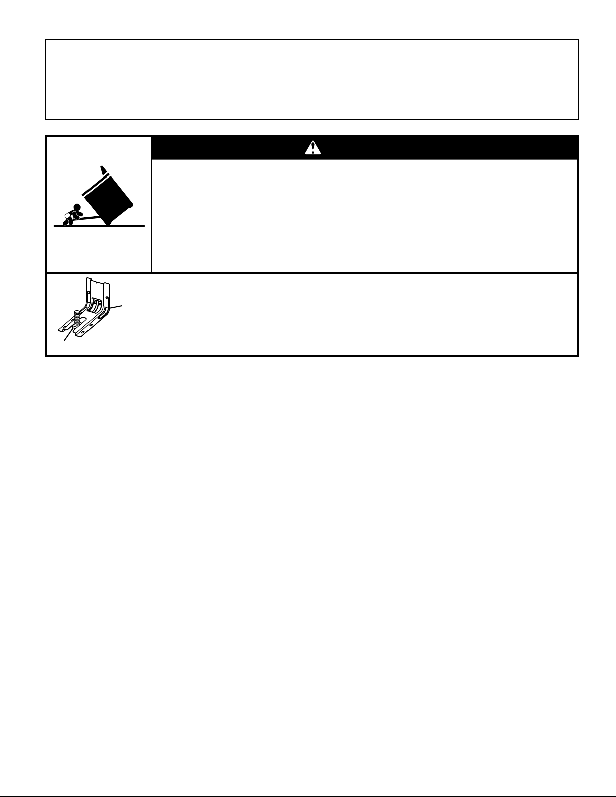
WARNING
Tip Over Hazard
A child or adult can tip the range and be killed.
Install anti-tip bracket to floor or wall per installation instructions.
Slide range back so rear range foot is engaged in the slot of the anti-tip bracket.
Re-engage anti-tip bracket if range is moved.
Do not operate range without anti-tip bracket installed and engaged.
Failure to follow these instructions can result in death or serious burns to children and adults.
To verify the anti-tip bracket is installed and engaged:
Anti-Tip
Bracket
Range Foot
• Slide range forward.
• Look for the anti-tip bracket securely attached to floor or wall.
• Slide range back so rear range foot is under anti-tip bracket.
• See installation instructions for details.
3

INSTALLATION REQUIREMENTS
Tools and Parts
Gather the required tools and parts before starting installation.
Read and follow the instructions provided with any tools listed
here.
Tools Needed
■ Tape measure
■ Phillips
screwdriver
■ Flat-blade
screwdriver
■ 1/8 " (3 mm) at-
blade screwdriver
■ Level
■ Drill
■ Adjustable wrench
■ Slip joint pliers
■ Pipe wrench
■ 15⁄16" (2.4 cm)
combination
wrench
■ 1⁄8" (3.2 mm)
drill bit (for wood
oors)
■ Marker or pencil
Parts Supplied
Check that all parts are included.
■ Propane/Natural gas conversion kit (dual fuel models only)
■ Blower mounting/venting template
■ Grease lter (packaged in place)
■ Oven racks (3)
■ Blower motor kit (under unit)
■ Blower cover kit (packed in cavity)
■ 10-32 hex nuts (attached to terminal block) (3)
■ Direct wire lugs (3)
■ #12 x 1
■ Anti-tip bracket (inside oven cavity)
Anti-tip bracket must be securely mounted to the back wall
5
⁄8" (4.1 cm) screws (for mounting anti-tip bracket) (2)
or oor. Thickness of ooring may require longer screws
to anchor bracket to suboor. Longer screws are available
from your local hardware store.
■ 5¹⁄2" (14 cm) hole saw (round
ducting)
■ Saw for 3¹⁄4" x 10" (8.3 x
25.4 cm) rectangle vent
■ #2 square bit and driver
■ Flashlight
■ Masking tape
■ Pipe-joint compound resistant
to natural and Propane gases
■ 3⁄16" (4.8 mm) carbide-tipped
masonry drill bit (for concrete/
ceramic oors)
■ Noncorrosive leak-detection
solution
■ Sheet metal aluminum tape
For Propane/Natural Gas
Conversions
■ 1/2" (13 mm) combination
wrench
■ 1/4" (6 mm) nut driver
■ 9/32" (7 mm) nut driver
Parts Needed
■ Use an approved vent cap for proper performance. If an
alternate wall or roof cap is used, be certain the cap size
is not reduced and that it has a backdraft damper.
■ After determining your vent installation, one of the following
is needed:
5" (12.7 cm) Round surface wall cap damper –
Order Part Number A405.
6" (15.2 cm) Round surface wall cap damper –
Order Part Number A406.
NOTE: If using 6" (15.2 cm) round venting, you will need
a 5" (12.7 cm) to 6" (15.2 cm) round vent transition.
3¼" x 10" (8.3 x 25.4 cm) Surface wall cap damper –
Order Part Number A403.
To order, see the “Assistance or Service” section of the Use and
Care Guide:
– Metal ducting
– Vent clamp
– Aluminum foil tape
Check local codes and consult gas supplier. Check existing
gas supply and electrical supply. See the appropriate “Electrical
Requirements” and “Gas Supply Requirements” sections.
It is recommended that all electrical connections be made by
a licensed, qualied electrical installer.
Optional Parts
To purchase these or any other accessories, please reference
the “Accessories” section of the Use and Care Guide for
contact information.
■ Side Trim Kits:
5/8" (1.7 cm) Black – Order Part Number W10675026
5/8" (1.7 cm) Stainless Steel – Order Part Number
W10675028
1¹⁄8" (2.9 cm) Black – Order Part Number W10731886
1¹⁄8" (2.9 cm) Stainless Steel – Order Part Number
W10731887
■ Backsplash Kits:
High 6" (15.2 cm) Black – Order Part Number W10655449
High 6" (15.2 cm) Stainless Steel – Order Part Number
W10655450
4
Location Requirements
A
IMPORTANT: Observe all governing codes and ordinances.
Do not obstruct ow of combustion and ventilation air.
■ It is the installer’s responsibility to comply with installation
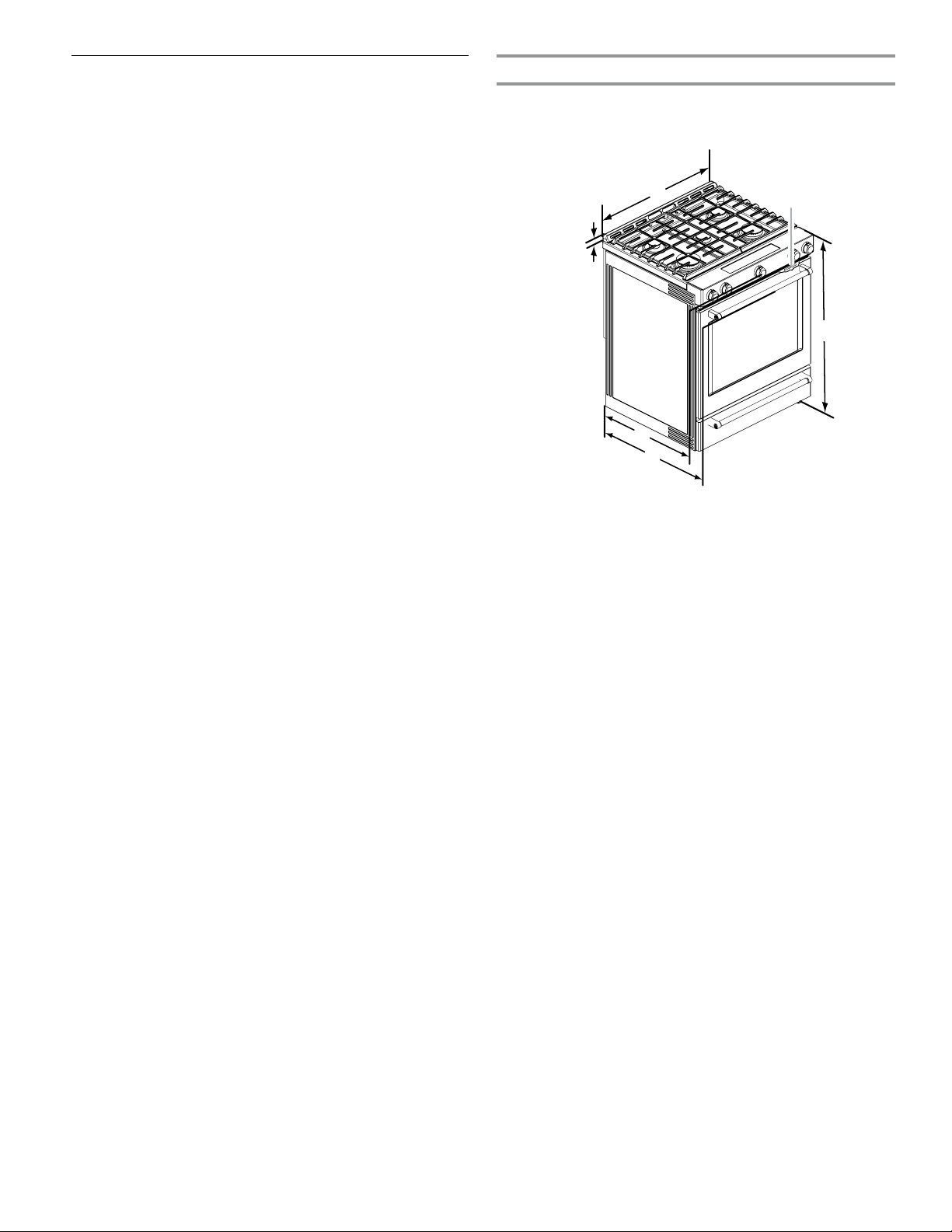
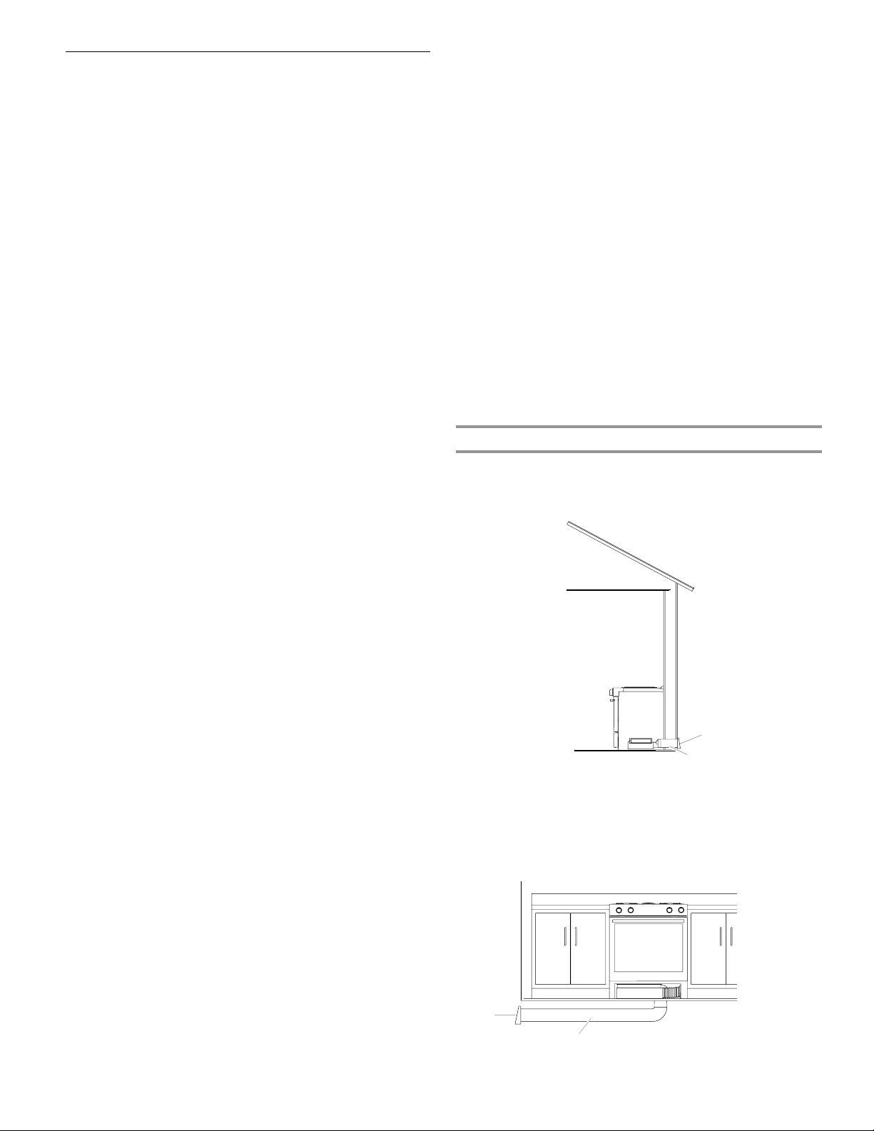
Product Dimensions
This manual covers several models. Your model may appear
different from the models depicted. Dimensions given are
maximum dimensions across all models.
clearances specied on the model/serial/rating plate. The
model/serial/rating plate is located behind the oven door
on the top right-hand side of the oven frame.
■ The range should be located for convenient use in the
B
C
kitchen.
■ Recessed installations must provide complete enclosure
of the sides and rear of the range.
■ All openings in the wall or oor where range is to be
installed must be sealed.
■ Cabinet opening dimensions that are shown must be used.
D
Given dimensions are minimum clearances.
■ The anti-tip bracket must be installed. To install the
anti-tip bracket shipped with the range, see “Install
Anti-Tip Bracket” section.
■ Grounded electrical supply is required. See the appropriate
“Electrical Requirements” section.
■ Proper gas supply connection must be available. See “Gas
E
F
Supply Requirements” section.
■ Contact a qualied oor covering installer to check that
the oor covering can withstand at least 200°F (93°C).
■ Use an insulated pad or 1/4" (6.4 mm) plywood under
range if installing range over carpeting.
IMPORTANT: To avoid damage to your cabinets, check
with your builder or cabinet supplier to make sure that the
materials used will not discolor, delaminate, or sustain other
damage. This oven has been designed in accordance with the
requirements of UL and CSA International and complies with
the maximum allowable wood cabinet temperatures of 194°F
(90°C).
Mobile Home – Additional Installation Requirements
The installation of this range must conform to the Manufactured
Home Construction and Safety Standard, Title 24 CFR,
A. 1³⁄16" (3.0 cm) height from
cooktop to top of vent
B. 297⁄8" (75.9 cm)
C. Model/serial/rating plate
(located behind the oven door
on the top right-hand side of
the oven frame)
D. 36" (91.4 cm) height to top of
cooktop edge with leveling
legs screwed in all the way*
E. 285⁄16" (71.9 cm) max. depth
from front of console to back
of range
F. 287⁄8" (73.3 cm) max. depth
from handle to back of range
IMPORTANT: Range must be level after installation. Follow
the instructions in the “Level Range” section. Using the cooktop
as a reference for leveling the range is not recommended.
* Range can be raised approximately 1" (2.5 cm) by adjusting
the leveling legs.
Part 3280 (formerly the Federal Standard for Mobile Home
Construction and Safety, Title 24, HUD Part 280). When such
standard is not applicable, use the Standard for Manufactured
Home Installations, ANSI A225.1/NFPA 501A or with local
codes.
In Canada, the installation of this range must conform with the
current standards CAN/CSA-A240-latest edition or with local
codes.
Mobile Home Installations Require:
■ When this range is installed in a mobile home, it must be
secured to the oor during transit. Any method of securing
the range is adequate as long as it conforms to the
standards listed above.
■ Four-wire power supply cord or cable must be used in a
mobile home installation. The appliance wiring will need
to be revised. See “Electrical Requirements – U.S.A. Only”
section.
5
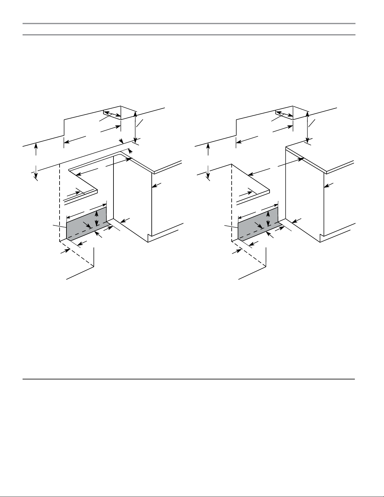
Cabinet Dimensions
Cabinet opening dimensions shown are for 25" (64.0 cm) countertop depth, 24" (61.0 cm) base cabinet depth and 36" (91.4 cm)
countertop height.
IMPORTANT: If installing a range hood or microwave hood combination above the cooking surface, follow the range hood or
microwave hood combination installation instructions for dimensional clearances above the cooktop surface.
Range may be installed next to combustible walls with zero clearance.
NOTE: When installed in a slide-in cutout, the front of oven door may protrude beyond the base cabinet.
Slide-in Cutout Freestanding Cutout
B
D
C
M
A
E
L
F
H
I
J
G
K
J
A. 18" (45.7 cm) upper side cabinet to countertop
B. 13" (33 cm) max. upper cabinet depth
C. 30" (76.2 cm) min. opening width
D. For minimum clearance to top of cooktop, see NOTE*.
E. 30" (76.2 cm) min. opening width
F. 3" (7.6 cm) min. clearance from both sides of range to side wall
or other combustible material
G. The shaded area is recommended for installation of rigid gas pipe
and grounded outlet.
H. 203/8" (51.8 cm)
I. 7¹¹⁄16" (19.5 cm)
J. 4¹³⁄16" (12.2 cm)
K. 3¹¹⁄16" (9.4 cm) plus measurement of M
L. Cabinet door or hinges should not extend into the cutout.
M. Remaining counter depth should not exceed 2¼" (5.7 cm).
B
D
C
A
E
L
F
H
I
J
G
K
J
A. 18" (45.7 cm) upper side cabinet to countertop
B. 13" (33 cm) max. upper cabinet depth
C. 30" (76.2 cm) min. opening width
D. For minimum clearance to top of cooktop, see NOTE*.
E. 30" (76.2 cm) min. opening width
F. 3" (7.6 cm) min. clearance from both sides of range to side wall
or other combustible material
G. The shaded area is recommended for installation of rigid gas pipe
and grounded outlet.
H. 203/8" (51.8 cm)
I. 7¹¹⁄16" (19.5 cm)
J. 4¹³⁄16" (12.2 cm)
K. 3¹¹⁄16" (9.4 cm)
L. Cabinet door or hinges should not extend into the cutout.
* NOTE: 24" (61.0 cm) minimum when bottom of wood or metal cabinet is shielded by not less than 1⁄4" (6.4 mm) ame retardant millboard covered
with not less than No. 28 MSG sheet steel, 0.015" (0.4 mm) stainless steel, 0.024" (0.6 mm) aluminum or 0.020" (0.5 mm) copper.
30" (76.2 cm) minimum clearance between the top of the cooking platform and the bottom of an uncovered wood or metal cabinet.
6
Venting Requirements
A
B
A
B
IMPORTANT: This range must be exhausted outdoors unless
you are using ductless venting. See the “Venting Methods”
section.
■ Do not terminate the vent system in an attic or other
enclosed area.
■ Use an approved vent cap for proper performance. If an
alternate wall or roof cap is used, be certain the cap size
is not reduced and that it has a backdraft damper.
■ Vent system must terminate to the outside unless you are
using a ductless vent kit.
■ Use a 5" (12.7 cm) or 6" (15.2 cm) round metal vent
or a 3¼" x 10" (8.3 cm x 25.4 cm) rectangular vent.
■ Rigid metal vent is recommended. For best performance,
do not use plastic or metal foil vent.
■ If a joist or stud must be cut, then a supporting frame must
be constructed.
■ The size of the vent should be uniform.
■ The vent system must have a damper.
■ Seal all joints in the vent system.
■ Use caulking to seal exterior wall or roof opening around
the cap.
■ Determine which venting method is best for your
application.
For Best Performance:
■ Use 26-gauge minimum galvanized or 25-gauge minimum
aluminum metal vent. Poor quality pipe ttings can reduce
airow. For external venting, exible metal vent is not
recommended.
NOTES:
■ For external venting, exible metal vent is not
recommended. Flexible vent creates back pressure
and air turbulence that greatly reduce performance.
■ Local codes may require a heavier gauge material.
■ Metal duct may be reduced to 30-gauge galvanized steel
or 26-gauge aluminized steel if allowed by local codes.
This reduction is based on information in the International
Residential Codes Section M1601.1 (2006 edition).
■ Avoid installing 2 elbows together.
■ Use no more than three 90° elbows.
■ Make sure there is a minimum of 18" (45.7 cm) of straight
vent between the elbows if more than one elbow is used.
Elbows too close together can cause excess turbulence
that reduces airow.
■ Do not use a 5" (12.7 cm) elbow in a 6" (15.2 cm)
or 3¼" x 10" (8.3 x 25.4 cm) system.
■ Do not reduce to a 5" (12.7 cm) system after using
a 6" (15.2 cm) or 3¼" x 10" (8.3 x 25.4 cm) ttings.
■ Avoid forming handmade crimps. Handmade crimps
may restrict airow.
The length of vent system and number of elbows should be
kept to a minimum to provide efcient performance.
The maximum equivalent length of the vent system is 60 ft
(18.3 m). For altitudes above 4,500 ft (1272 m), reduce
recommended vent run by 20% for best performance.
Cold Weather Installations
An additional backdraft damper should be installed to
minimize backward cold air ow and a thermal break installed
to minimize conduction of outside temperatures as part
of the vent system. The damper should be on the cold
air side of the thermal break.
Order Part Number 708786A for a 5" (12.7 cm) thermal break.
Order Part Number 715557A for a 6" (15.2 cm) thermal break.
To order, see the “Assistance or Service” section of the Use
and Care Guide.
Makeup Air
Local building codes may require the use of makeup air
systems when using ventilation systems greater than specied
CFM of air movement. The specied CFM varies from locale
to locale.
Consult your HVAC professional for specic requirements
in your area.
Venting Methods
Common venting methods are shown for a downdraft range.
The downdraft range may be vented through the wall or oor.
Wall Venting
A. Wall cap
B. Venting
Floor Venting
Venting Between Floor Joists
A. Wall cap
B. Venting
7
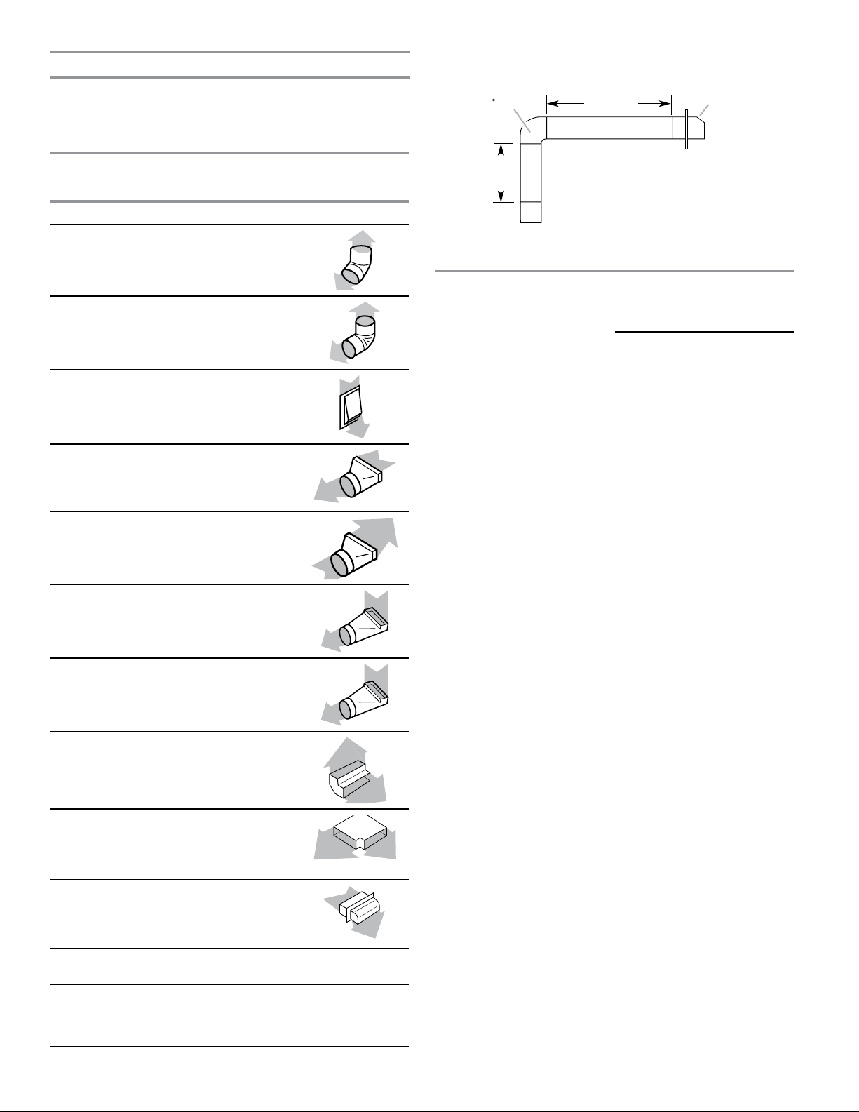
Calculating Vent System Length
90 elb
Wall cap
Example 6" (15.2 cm) vent system
Venting Between Floor Joists
IMPORTANT: This range is rated at 60 ft (18.3 m) of 6"
(15.2 cm) or 30 ft (9.15 m) of 5" (12.7 cm) straight duct. To
calculate the length of the system you need, add the equivalent
feet (meters) for each vent piece used in the system.
5" (12.7 cm)
or 6" (15.2 cm)
Vent Piece
Round
Straight round
45° elbow
2.5 ft
(0.8 m))
90° elbow
5.0 ft
(1.5 m)
6" (15.2 cm) wall cap
0.0 ft
(0.0 m)
3¹⁄4" x 10" (8.3 cm x 25.4 cm)
to 6" (15.2 cm) transition
4.5 ft
(1.4 m)
6 ft (1.8 m)
2 ft
(0.6 m)
ow
Maximum length = 60 ft (18.3 m)
1- 90° elbow = 5 ft (1.5 m)
8 ft (2.4 m) straight = 8 ft (2.4 m)
1 - wall cap = 0 ft (0 m)
System length = 13 ft (3.9 m)
NOTE: For external venting, a exible vent is not
recommended. Flexible vents create back pressure and air
turbulence that greatly reduce performance.
6" (15.2 cm) to 3¹⁄4" x 10"
(8.3 cm x 25.4 cm) transition
3¹⁄4" x 10" (8.3 cm x 25.4 cm)
to 6" (15.2 cm) 90° elbow
transition
6" (15.2 cm) to 3¹⁄4" x 10"
(8.3 cm x 25.4 cm) 90° elbow
transition
3¹⁄4" x 10" (8.3 cm x 25.4 cm)
90° elbow
3¹⁄4" x 10" (8.3 cm x
25.4 cm) at elbow
3¹⁄4" x 10" (8.3 cm x
25.4 cm) wall cap
1 ft
(0.3 m)
5.0 ft
(1.5 m)
5.0 ft
(1.5 m)
5.0 ft
(1.5 m)
12.0 ft
(3.7 m)
0.0 ft
(0.0 m)
Straight 3¹⁄4" x 10"
(8.3 cm x 25.4 cm)
5" (12.7 cm) thermal break
Part Number 708786A
6" (15.2 cm) thermal break
Part Number 715557A
8
2.0 ft
(0.6 m)
Electrical Requirements – U.S.A. Only
WARNING
Electrical Shock Hazard
Electrically ground range.
Failure to do so can result in death, fire, or
electrical shock.
Be sure that the electrical connection and wire size are
adequate and in conformance with the National Electrical
Code, ANSI/ NFPA 70-latest edition and all local codes and
ordinances.
A copy of the above code standards can be obtained from:
National Fire Protection Association
1 Batterymarch Park
Quincy, MA 02169-7471
WARNING: Improper connection of the equipment-grounding
conductor can result in a risk of electric shock. Check with a
qualied electrician or service technician if you are in doubt as
to whether the appliance is properly grounded. Do not modify
the power supply cord plug. If it will not t the outlet, have a
proper outlet installed by a qualied electrician.
Electrical Connection
Check local codes and consult gas supplier. Check
existing electrical supply and gas supply. See “Gas Supply
Requirements” section.
It is recommended that all electrical connections be made by
a licensed, qualied electrical installer.
■ Range must be connected to the proper electrical voltage
and frequency as specied on the model/serial/rating plate.
The model/serial/rating plate is located on the right vertical
surface of the oven door frame. Refer to the illustrations
in the “Product Dimensions” section of the “Location
Requirements” section.
■ This range is manufactured with a 4-wire power supply
cord rated at 240 V, 40 A, rated at 194°F (90°C)
and investigated for use with this range.
■ When a 4-wire, single phase 240 V, 60 Hz, AC only
electrical supply is available, a 40 A minimum circuit
protection is required on 30" (76.2 cm) ranges, fused
on both sides of the line.
■ A time-delay fuse or circuit breaker is recommended.
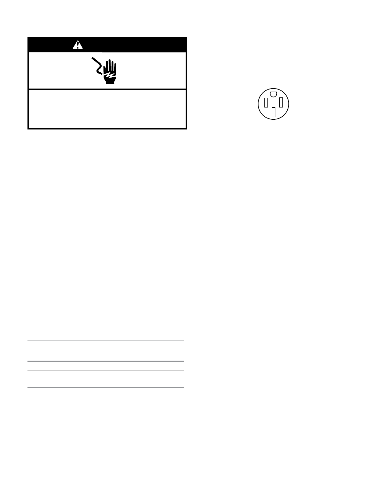
■ This range is equipped with a UL or CSA International
Certied Power Cord intended to be plugged into
a standard 14-50R wall receptacle. Be sure the wall
receptacle is within reach of range’s nal location.
■ Do not use an extension cord.
■ The wiring diagram is located on the back of the range
or in a clear plastic bag.
Specied Rating of
Power Supply Cord Kit
Range Rating*
120/240 Volts 120/208 Volts Amps Temp Rating
8.8–16.5 kW 7.8–12.5 kW 40 or 50 194°F (90°C)
16.6–22.5 kW 12.6–18.5 kW 50 194°F (90°C)
* The NEC calculated load is less than the total connected load listed
on the model/serial/rating plate.
and Circuit Protection
9
 Loading...