


INSTALLER: LEAVE THESE INSTRUCTIONS WITH THE APPLIANCE
INSTALLATION MANUAL
Dual-Fuel 30-inch Wide
Jenn-Air Downdraft Range
PLEASE KEEP THIS MANUAL FOR FUTURE REFERENCE
THE MANUAL IS INTENDED TO ASSIST IN THE INITIAL INSTALLATION AND ADJUSTMENTS OF THE RANGE.
SPECIAL WARNING
Only qualified personnel should install or service this range.
Read “Safety Instructions” in Use & Care book before using range.
Improper installation, adjustment, alteration, service, maintenance or use of range can result in serious injury or property damage.
CLEARANCE DIMENSIONS
For complete information in regard to installation of Jenn-Air range, see figures 1, 2, 3 and 4. For SAFETY CONSIDERATIONS, do not install a range in any combustible cabinetry which is not in accord with the installation clearances shown in figure 1.
CAUTION: This range has been designed in accordance with the requirements of various safety agencies and complies with the maximum allowable wood cabinet temperatures of 194 F. If this range is installed with cabinets that have a lower working temperature than 194 F, discoloration, delamination or melting may occur.
ALL RANGES CAN TIP AND CAUSE INJURIES TO PERSONS.
INSTALL ANTI-TIP DEVICES PACKED WITH RANGE.
FOLLOW ALL INSTALLATION INSTRUCTIONS.
Your range may not be equipped with some of the features referred to in this manual.
ENGLISH |
' |
PP. 1-16 |
ESPAÑOL |
' |
pág. 17-32 |
FRANCAIS |
' |
p. 33-48 |
8101P534-60
(01-03-00)

30 |
JENN-AIR RANGES |
FIGURE 2
NOTES:
1.Provide for either a 3-wire or 4-wire 120/208, 120/240 volt outlet per applicable cord in shaded area shown. Refer to installation instructions for proper positioning of outlet. This is also the recommended gas line location.
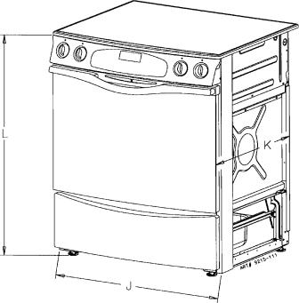
2.Dimension K (figure 3, page 3) is from the wall to the side edge of the oven door. It does not include the curvature of the glass or the depth of the handle.
3.Dimension L (figure 3, page 3) is with the leveler legs adjusted all the way in. This may vary slightly upon leveling leg adjustment.
4.Do not use grout, epoxy, etc., to install this unit. Installation must allow for removal of this appliance from the installed location for purposes of servicing.
-2-
30 |
|
JENN-AIR RANGES |
|
|||
|
|
|
|
Slide-In Range |
|
|
|
|
|
|
|
|
|
|
|
|
|
Dimensions |
|
|
|
|
|
J |
Inches |
|
Centimeters |
|
|
|
A |
25 |
|
63.5 |
|
|
|
B |
24 |
|
61.0 |
|
|
|
C |
30 |
|
76.2 |
|
|
|
D |
36 |
|
91.4 |
|
|
|
E |
23 5/8 |
|
60.0 |
|
|
|
F |
23 1/4 |
|
59.1 |
|
|
|
G |
5 1/2 |
|
14.0 |
|
|
|
H |
10 |
|
25.4 |
|
|
|
J |
29 7/8 |
|
75.9 |
|
|
|
K 2* |
26 3/16 |
|
66.5 |
|
FIGURE 3 |
|
L3* |
35 3/4 |
|
90.8 |
|
|
M |
2 1/4 |
|
5.7 |
|
|
|
|
|
|||
* SEE NOTES ON PAGE 2
-3-
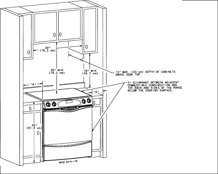
FIGURE 4
Dimension “A” is to be a minimum of 3-inches (7.5 cm).
Check the range model number plate to see if the range is approved for installation in mobile homes and/or recreational vehicles. If approved the following items are applicable.
MOBILE HOMES
The installation of a range designed for mobile home installation must conform with the Manufactured Home Construction and Safety Standard, Title 24 CFR, Part 3280 [formerly the Federal Standard for Mobile Home Construction and Safety, Title 24 HUD, (Part 280)] or, when such standard is not applicable, the Standard for Manufactured Home Installations, ANSI A225.1/NFPA 501A, or with local codes.
In Canada the range must be installed in accordance with the current CSA Standard C22.1 - Canadian Electrical Code Part 1 and Section Z240.4.1 - Installation Requirements for Gas Burning Appliances in Mobile Homes (CSA Standard CAN/CSA - Z240MH).
RECREATIONAL VEHICLES
The installation of a range designed for recreational vehicles must conform with state or other codes or, in the absence of such codes, with the Standard for Recreational Vehicles, ANSI A119.2-latest edition.
In Canada the range must be installed in accordance with CAN/CSA - Z240.6.2 - Electrical Requirements for R.V.’s (CSA Standard CAN/CSA - Z240 RV Series) and Section Z240.4.2 - Installation Requirements for Propane Appliances and Equipment in R.V.’s (CSA Standard CAN/CSA - Z240 RV Series).
LOCATING THE RANGE
Do not set range over holes in the floor or other locations where it may be subject to strong drafts. Any opening in the wall behind the range and in the floor under the range should be sealed. Make sure the flow of combustion or ventilation air is not obstructed.
NOTE: A range should NOT be installed over kitchen carpeting.
-4-

ANTI-TIP DEVICE INSTALLATION INSTRUCTIONS
NOTE: A risk of range tip over exists if the appliance is not installed in accordance with the installation instructions provided. The proper use of this device minimizes the risk of TIP-OVER. In using this device the consumer must still observe the safety precautions as stated in the USE and CARE MANUAL and avoid using the oven door and/or lower drawer as a step stool.
Installation instructions are provided for wood and cement in either floor or wall. Any other type of construction may require special installation techniques as deemed necessary to provide adequate fastening of the ANTI-TIP bracket to the floor or wall.
STEP 1 - Locating The Bracket (see figure 5)
A.Determine where either the right or left rear “edge” of the range will be located and mark the floor or wall.
B.Place the BRACKET 15/16 from the marked “EDGE” toward center of opening and against the back wall as shown in figure 5.
C.Use the bracket as a template and mark the required holes, as shown in figure 5 for the type of construction you will be using.
STEP 2 - Anti-Tip Bracket Installation
A.Wood Construction:
1.Floor: Locate the center of the two holes identified in figure 5 as “HOLES FOR FLOOR”. Drill a 1/8 pilot hole in the center of each hole (a nail or awl may be used if a drill is not available). Secure the ANTI-TIP bracket to the floor with the two screws provided. Proceed to STEP 3.
2.Wall: Locate the center of the two holes identified in figure 5 as “HOLES FOR WALL. Drill an angled
1/8 pilot hole in the center of each hole as shown in figure 6. (A nail or awl may be used if a drill is not available). Secure the ANTI-TIP bracket to the wall with the two screws provided as shown in figure 6. Proceed to STEP 3.
B.Cement or Concrete Construction:
1.Suitable screws for concrete construction can be obtained at a hardware store. Drill the required size hole for the screws obtained into the concrete at the center of the holes identified in figure 5 as “HOLES FOR FLOOR”. Secure the ANTI-TIP bracket to the floor. Proceed to STEP 3.
STEP 3 - Range Installation
A.Align the range to its designated location and slide it back into position. Make sure that the leveling foot is fully inserted into and secured by the ANTI-TIP bracket. Note: A minimum clearance of 1/4 is required between the range and the leveling foot that will engage the ANTI-TIP bracket, see figure 6.
B.For safety considerations as well as optimum performance adjust the range so that it is level. This may be checked by placing a spirit level or a large pan of water on the cooktop or the oven rack. Jenn-Air ranges require total removal from cabinet before an adjustment can be made.
C.To check the range for proper installation of the anti-tip bracket: Use a flashlight and look underneath the bottom of the range to see that one of the rear leveling legs is engaged in the bracket slot.
D.Proceed with the remainder of the installation instructions.
FIGURE 5 |
|
FIGURE 6 |
|
|
|
-5-
CONNECTING THE RANGE
ELECTRIC SUPPLY
The range must be installed in accordance with Local and National Electric Code (NEC) ANSI/NFPA No. 70-latest edition. See rating plate for total connected KW rating.
ELECTRIC SUPPLY (Canada)
The range must be installed in accordance with Local and Canadian Electric Code CSA STD.C22.1 latest edition. See rating plate for total connected KW rating.
OUTSIDE WIRING
Your local utility company will tell you whether the present electric service to your home is adequate. It may be necessary to increase the size of the wiring to the house and service switch to take care of the electrical load demanded by the range. The kilowatt rating for the range is specified on the rating plate located on the front of the range.
HOUSE WIRING
Most local Building Regulations and Codes require that all electrical wiring be done by licensed electricians. All wiring should conform to Local and National Electrical Codes. This range requires a single phase three wire 120/240 or a 120/208 volt, 60 Hz, AC circuit. Wiring codes require a separate circuit be run from the main entrance panel to the range and that it be equipped with separate disconnect switch and fuses, either in the main entrance panel or in a separate switch and fuse box. In some communities, a solid or flexible continuous armored conduit must be used from main entrance panel to the terminal box on the rear of the range. Others will permit the termination of the range circuit at a polarized three or four wire plug-in outlet placed at a convenient point near the back of the range. The range is then connected to this outlet through an approved range connector (pigtail) fastened securely to the terminal block with proper strain relief at the range and a three or four pronged plug at the opposite end.
User may experience occasional circuit tripping if Ground Fault Circuit Interrupter (GFCI) outlet or breaker is in use
RANGE CONNECTIONS
Some models are shipped direct from the factory with service cords (pigtails) attached. There are no range connections necessary on these models. Just plug into the range outlet. On models not provided with a service cord, connection to the power supply is necessary. REMEMBER - only a 4-conductor cord is to be used on new branch-circuit installations (1996 NEC), mobile homes, recreational vehicles, or in an area where local codes prohibit grounding through the neutral conductor. Hence, 4-wire service MUST be provided for such installations. 3-wire service may be used when permitted by local code. USE COPPER OR ALUMINUM CONDUCTORS. Main terminal block is recognized for Copper or Aluminum conductors. If a flexible power cord is required, it is recommended a cord no longer than 4 ft. be used. Make connections as explained below and with reference to the appropriate illustration (see figures 8 and 9). After installation, insure tightness of all electrical connections and replace all covers.
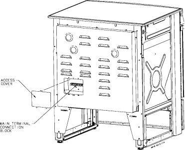
Remove terminal block access cover from range back. (See figure 7).
RANGE CONNECTIONS (Canada)
This model was shipped direct from the factory with service cord (pigtail) attached. There are no range connections necessary. Just plug into the range outlet. See figure 2 on page 3 for outlet location.
NOTE: Cord replacement - ONLY a power supply cord rated at 240 volts minimum, 40 amperes or 50 amperes power supply cord that is marked for use with nominal 1 3/8 (34.93 mm) diameter connection opening, with closed loop terminals and marked for use with ranges shall be used.
FIGURE 7
-6-
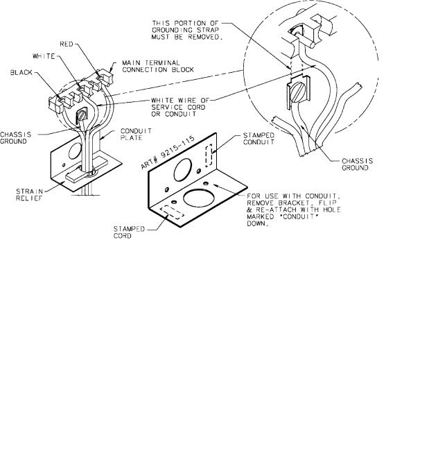
3-WIRE SERVICE CORD OR CONDUIT INSTALLATION
1.Insure that the copper ground strap IS CONNECTED between the middle post of the main terminal connection block and the range chassis.
2.The middle wire of the service cord or ground lead of 3-wire conduit MUST connect to the neutral (middle) post of the main terminal block. The other two wires of the service cord or conduit connect to the outside posts of the main terminal connection block. Polarity is unimportant.
3.A appropriate strain relief for service cord or conduit must be attached to the conduit plate.
FIGURE 8
ACCEPTABLE 3-WIRE PLUG INSTALLATION
4-WIRE SERVICE CORD OR CONDUIT INSTALLATION
(MOBILE HOMES OR AS REQUIRED BY CODES)
1.The copper ground strap connected between the neutral (middle) post of the main terminal block and the chassis MUST be cut off as shown in figure 9. Save the green ground screw to attach the ground from the 4 wire cord. Only a 4 wire cord or conduit should be used.
2.The ground wire from the service cord or conduit must connect to the range chassis using the green ground screw.
3.The white wire of the service cord or conduit must connect to the neutral (middle) post of the main terminal block. The other two wires of the service cord or conduit connect to the red and black posts of the main terminal block, respectively.
4.An appropriate strain relief for service cord or conduit must be attached to the conduit plate.
CONVERSION FROM 3-WIRE TO 4-WIRE
SERVICE
(Model With 3-Wire Service Cord Attached)
Disconnect range from power. Remove the access cover on back of range and remove the 3-wire service cord from the main terminal block. Follow instructions as outlined in figure 9 to connect the 4-wire service cord.
NOTE: Cord replacement - ONLY a power supply cord rated at 240 volts minimum, 40 amperes or 50 amperes power supply cord that is marked for use with nominal 1 3/8 (34.93 mm) diameter connection opening, with closed loop terminals and marked for use with ranges shall be used.
FIGURE 9
ACCEPTABLE 4-WIRE PLUG INSTALLATION
-7-
DOWNDRAFT INSTALLATION INSTRUCTIONS
SDetermine where you will be locating the electrical outlet. It must be in the floor or on the wall within the area shown in figure 2 or 3.
SDetermine how you will be venting your downdraft blower. You may vent through the rear wall, the floor, or the sides. When locating the downdraft vent opening make sure it will not interfere with your electrical outlet.
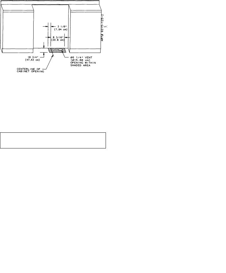
a.Through the rear wall. (See figure 10) Mark the centerline of the cabinet opening on the rear wall. The 6 1/4 vent opening must be located on a centerline 8 3/8 above the floor and within 3 1/4 to the right (when facing the cabinet opening) of the centerline of the cabinet opening as shown in figure 10.
Cut a 6 1/4 diameter hole on the marked centerline making sure to miss any wall studs. Install the blower as shown in figure 12.
b.Through the floor. (See figure 11) Making sure to miss any floor joists cut a 6 1/4 diameter hole in the shaded area as shown in figure 11. Install the blower as shown in figure 12.
NOTE: If the floor is a concrete slab, see the enclosed ducting instructions.
c.Through the Left or Right side cabinet.
(See figure 13).
1.Additional materials required:
1 pc 5 diameter x 19 long (12.7 cm x 48.26 cm).
Flex duct (P/N 702935).
1 pc 6 (15.25 cm) 90_ elbow.
2 Hose Clamps (P/N 702331).
1 pc 5 to 3 1/4 x 10 (12.7 cm to 8.26 cm x 25.4 cm) Transition.
2 pcs Wood spacers (right side vent only)
1 1/2 thick x 9 long (3.81 cm x 22.68 cm).
(See your local dealer for these accessories).
2.Cut hole in either the left or right side of the cabinet wall as shown in figure 13.
Figure 10
Figure 11
Figure 12
Figure 13
-8-
3.Make cutout in the cabinet floor of either the right or left side cabinet as shown in figures 14 or 15.
4.Relocate the mounting brackets on the blower housing as shown in figure 17.
NOTE: The mounting brackets shown in figure 16 are as assembled at the factory for floor or rear wall venting.
a.Right side venting (figure 17).
1.Remove nuts from studs 1, 2 and 3 on the motor side.
2.Remove bracket and reattach with studs 1 and 2 inserted in holes A and C and replace 3 nuts.
3.Remove nuts from studs 5, 6 and 7 on air inlet side.
4.Remove bracket and reattach with studs 5 and 6 inserted in holes D and B and replace 3 nuts.
b.Left side venting (figure 17).
1.Remove nuts from studs 1, 2, 3 and 4 on motor side.
2.Remove bracket.
3.Rotate motor and cover assembly 180 degrees.
4.Reattach bracket with studs 4 and 1 inserted in holes A and C and replace all 4 nuts.
5.Remove nuts from studs 5, 6, 7 and 8 on inlet side.
6.Remove bracket and reattach with studs 8 and 5 inserted in holes D and B and replace all 4 nuts.
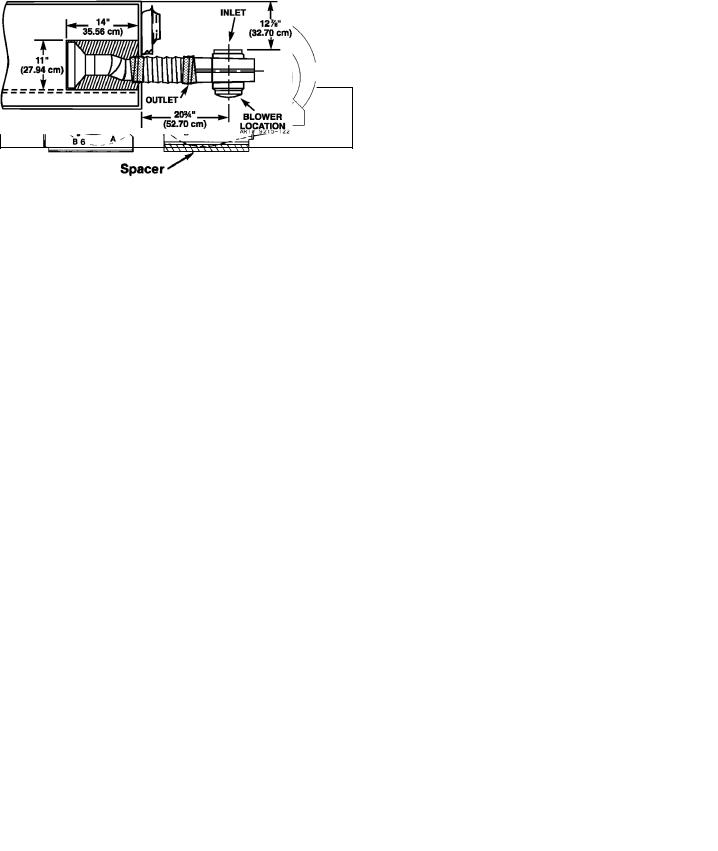
5.Attach the blower housing to the floor with the outlet towards the direction of the venting and the inlet towards the front of the cabinets. In addition, for left side venting, a spacer of approximately 1-1/2 thick x 9 long (3.81 cm x 22.86 cm) is required under the mounting bracket flanges of the blower assembly (see figure 17).
6.Remove the inside wire and outside string from the first 1-1/2 (3.81 cm) of one end of the 5 (12.7 cm) flex duct (P/N 702935). Stretch this end of the flex duct over the end of the 5 x 3-1/4 x 10 (12.7 cm x 25.4 cm) transition and secure with hose clamp (P/N 702331).
7.When the range is placed in position, feed the open end of the 5 (12.7 cm) flex duct through the hole in the cabinet side wall and attach to the outlet of the blower housing with hose clamp (P/N 702331). The transition should then be attached to the 3-1/4 x 10 (12.7 cm x 25.4 cm) ducting in the cabinet toe space through the cabinet floor cutout.
Figure 14
Left Cabinet (Top View)
Figure 15
Right Cabinet (Top View)
Figure 16
Blower Assembly
Figure 17
View from Air Inlet Side of Blower
-9-
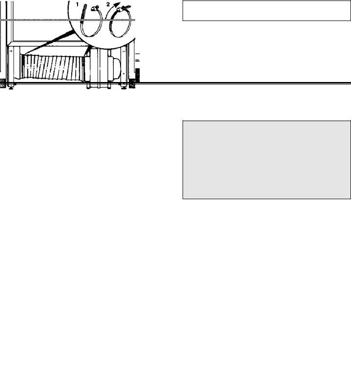
8.Install the 6 (15.24 cm) elbow of the blower housing and secure with duct tape. The open end of the elbow should be pointed to the left. Attach the 6 (15.24 cm) flex duct (provided with the range) to the elbow and to the range. Note: For right side venting, the 6 (15.24 cm) diameter flex duct may be cut in half and used in order to make assembly easier.
INSTALLING THE BLOWER
NOTE: Install the blower prior to installing the range.
SRefer to your duct plan. It may be easier to attach part of the ducting to the blower before it is installed.
SPosition the blower and attach to the floor with at least 2 screws.
SApply duct tape to blower exhaust duct joint. (See figure 12).
RANGE INSTALLATION
CONNECTING THE DOWNDRAFT BLOWER
TO ELECTRICAL (Figure 18)
SConnect the blower power cord to the blower motor housing.
Figure 18
INSTALLING THE FLEX DUCT TO BLOWER
SUse one of the duct clamps provided. Using a screw driver, tighten duct clamp to secure the flex duct to the inlet of the blower. (See figure 19).
Figure 19
INSTALLING THE RANGE
In The Commonwealth Of Massachusetts
This product must be installed by a licensed plumber or gas fitter when installed within the Commonwealth of Massachusetts.
A “T” handle type manual gas valve must be installed in the gas supply line to this appliance.
A flexible gas connector, when used, must not exceed a length of three (3) feet / 36 inches.
SAlign the range to its designated location and slide back into position. Make sure that the rear leveling leg is fully inserted and secured by the anti-tip bracket.
SAttach the other end of the flex duct to the plenum of the range using the second duct clamp. Tighten duct clamp to secure it to the plenum.
CHECK FOR OPERATION
SInstall the air filter. As you face the range, the top of the filter should rest against the left side of the vent opening. DO NOT OPERATE THE SYSTEM
WITHOUT THE FILTER.
SInstall the air grille over the vent opening.
SBe sure to remove all packing materials the oven from unit prior to applying power.
SSwitch electrical circuit breaker to the ON position.
SConsult USE and CARE MANUAL for proper operation.
-10-
CONNECTING APPLIANCE TO GAS SUPPLY
A QUALIFIED SERVICEMAN OR GAS APPLIANCE INSTALLER MUST MAKE THE GAS SUPPLY CONNECTION. Leak testing of the appliance shall be conducted by the installer according to the instructions given.
INSTALL GAS SHUTOFF VALVE
Install a manual shutoff valve in an accessible location in the gas line external to this appliance for the purpose of turning on or shutting off gas to the appliance.
Make the gas connection to the inlet of the pressure regulator on this appliance with a 1/2 male pipe thread. Use an approved pipe joint compound resistant to the action of LP gas at pipe connections. Test all joints for gas leaks with a soap and water solution or other accepted leak detection means. Never test for gas leaks with an open flame.
PRESSURE TESTING
The maximum gas supply pressure for the regulator supplied on this appliance is 14 Water Column. The test pressure for checking this regulator must be at least 6 Water Column for natural gas, and at least 11 Water Column for LP. It is shipped from the factory set for natural gas at 5 Water Column.
This appliance and its individual shutoff valve must be disconnected from the gas supply piping system during any pressure testing of that system at test pressures in excess of 1/2 PSIG (3.5 k Pa).
This appliance must be isolated from the gas supply piping system by closing its individual manual shutoff valve during any pressure testing of the gas supply piping system at test pressures equal to or less than 1/2 PSIG (3.5 k Pa).
APPLIANCE PRESSURE REGULATOR CONVERSION (See illustration “A”)
Follow the instructions below to convert the regulator for use with LP gas. (This appliance is shipped from the factory adjusted for use with natural gas.)
1.Unscrew the hex shaped cap from the neck of the regulator. (A wrench may be required to loosen the cap.)
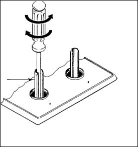
2.Within the cap is a plastic pin. Remove this pin from the cap by applying sideward pressure to the pin. (See illustration.)
3.Invert the pin and snap it back into place within the cap by applying even finger pressure at opposing edges of the pin’s circular disc. The pin must be seated firmly and squarely in the cap.
Pin replacement may be most easily accomplished by placing the cap on a flat horizontal surface, as shown in the illustration, and applying downward finger pressure at the edges of the pin’s disc.
MAXITROL REGULATOR
ILLUSTRATION “A”
HARPER-WYMAN REGULATOR
The reversible cap is labeled either “LP” or “NAT” and is easily recognized by the raised center coin slot (for Natural) or the center well (for LP).
ALTERNATE ILLUSTRATION “A”
4.Screw the cap securely back into place in the neck of the pressure regulator. (The cap need not be wrench-tightened upon replacement. Firm finger tightening will secure the cap.)
To convert regulator to LP insert a coin into the slot in the cap of the regulator and turn counterclockwise to loosen. Reverse (invert) cap, push down and turn clockwise to lock in place. When finished, the marking “LP” should be visible in the center well of the cap.
CONVERSION TO LP GAS (See illustration “B”)
This appliance is shipped from the factory equipped for use with natural gas. To convert it from natural gas for use with LP gas, perform steps 1 through 4.
1/2 OPEN END
WRENCH
|
TURN CLOCKWISE |
|
TURN |
TO TIGHTEN |
|
COUNTERCLOCKWISE |
ORIFICE HOOD |
|
TO REMOVE |
||
|
ILLUSTRATION “B”
1.Remove natural gas orifice hoods. Remove LP orifice, (if so equipped) in tube assemblies. Install color coded orifice hoods supplied. (SEE LP GAS CONVERSION
INSTRUCTIONS PAGE 15.)
2.Invert cap in convertible pressure regulator (if so equipped) located at entrance to gas manifold.
-11-

3.Adjust air shutters on individual burners for proper flame appearance.
4.Adjust low flame setting at each burner by turning adjustment screw in center of valve stem.
To make these conversion adjustments follow the instructions and illustrations (“A” through “D”).
IMPORTANT
Apply a non-corrosive leak detection fluid to all joints and fittings in the gas connection between the supply line shut-off valve and the range. Include gas fittings and joints in the range if connections were disturbed during installation. Check for leaks! bubbles appearing around fittings and connections will indicate a leak. If a leak appears, turn off supply line gas shut-off valve, tighten connections, turn on the supply line gas shut off valve, and retest for leaks. Never test for gas leaks with an open flame.
This appliance is shipped from the factory with orifice hoods drilled for use with natural gas. To convert from natural gas to LP, apply a 1/2 open-ended wrench to hex section of orifice hood. TURN COUNTERCLOCKWISE TO REMOVE. Save the Natural Gas orifice hoods just removed from this appliance for future use. Install color coded orifice hoods supplied. (SEE GAS CONVERSION INSTRUCTIONS PAGE 14.) TURN CLOCKWISE TO INSTALL. Hold dimension specified in illustration “B”.
CONTROL SETTINGS
The size and type of cookware and the amount and type of food being cooked will influence the setting needed for best cooking results. The setting indicated should serve as a guide while you become familiar with your cooktop.
Use the Hi flame setting to quickly bring foods to a boil or to begin a cooking operation. Then reduce to a lower setting to continue cooking. Never leave food unattended over a Hi flame setting.
Med setting is used to continue a cooking operation. Food will not cook any faster when a Hi flame setting is used than that needed to maintain a gentle boil. Remember, water boils at the same temperature whether boiling gently or vigorously.
Use Lo setting to keep food at serving temperatures without further cooking. You may find that some cooking may take place if the cookware is covered.
AIR SHUTTER ADJUSTMENT
(See illustration “C”)
This appliance is shipped from the factory with air shutters adjusted for use with natural gas. If further adjustment is necessary, or to reset for use with LP, adjust air shutters as follows:
Grill Burner and Surface Burner Cartridge Air Shutters (see illustration “C”).
SThe left hand air shutter controls the rear half of the burner.
SThe right hand shutter controls the front half.
SAccess to air shutters on the surface burner cartridge may be found through openings on the bottom of the cartridge housing.
Slide air shutter backward or forward to increase or decrease the size of the air opening. Air shutters fit snugly, so a screwdriver blade may be required to make this adjustment (see illustration.)
Observe change in flame appearance as the air shutter is moved. Adjustment is satisfactory when a clearly defined, even blue flame results at the high flame setting. The snug fit of the air shutter assures it will remain positioned correctly.
On any burner, closing the air shutter too far will cause the flame to become soft and yellow tipped. Opening the air shutter too wide will cause the flame to blow away from the burner ports. Proper adjustment will produce a sharp, clearly defined, even blue flame.
GRILL BURNER AIR SHUTTER & SURFACE BURNER
(IF SO EQUIPPED)
AIR OPENING
AIR SHUTTER
INSERT SCREWDRIVER BLADE IN SLOT AND TWIST WITH SLIGHT PRESSURE TO ALLOW AIR SHUTTER TO SLIDE EASILY.
ILLUSTRATION “C”
-12-
LOW FLAME ADJUSTMENT
(See illustration “D”)
This appliance is shipped from the factory with low and medium flame settings adjusted for use with natural gas. If further adjustment is necessary, or to readjust for use with LP, proceed as follows:
1.Light burner and set control knob for low flame.
2.Remove control knob from valve stem.
CAUTION: NEVER USE A METAL BLADE TO PRY KNOB OFF. IF KNOB CANNOT BE EASILY REMOVED, TUCK FOLDS OF A CLOTH DISHTOWEL UNDER THE KNOB AND PULL THE TOWEL UPWARD WITH STEADY, EVEN PRESSURE.
3.Insert a slender, thin-blade screwdriver into the recess at center of valve stem and engage blade with slot in adjusting screw.
4.Turn center stem adjusting screw to set flame size.
. . . clockwise to reduce.
. . . counterclockwise to increase.
5.Replace control knob when adjustment is completed.
Proper adjustment will produce a stable, steady blue flame of minimum size. The final adjustment should be checked by turning knob from high to low several times without extinguishing the flame.
This adjustment, at low setting, will automatically provide the proper flame size at medium setting.
COUNTERCLOCKWISE
TO INCREASE FLAME
SIZE
CLOCKWISE
TO REDUCE
SIZE
VALV
E
STEM
ILLUSTRATION “D”
-13-
NATURAL GAS TO PROPANE GAS (LP) CONVERSION INSTRUCTIONS
TO CONVERT APPLIANCE FOR USE WITH PROPANE GAS

 WARNING
Propane conversion is to be performed by a JENN-AIR AUTHORIZED SERVICE CONTRACTOR (or other qualified agency) in accordance with the manufacturer’s instructions and all codes and requirements of the authority having jurisdiction. Failure to follow instructions could result in serious injury or property damage. The qualified agency performing this work assumes responsibility for this conversion.
Natural gas supply line must have a natural gas service regulator. Inlet pressure to this appliance should be reduced to a maximum of 14 inches water column (0.5 pounds per square inch (P.S.I.) liquified petroleum (L.P.)/propane gas supply line must have a L.P. gas pressure regulator. Inlet pressure to this appliance should be reduced to a maximum of 14 inches water column (0.5 P.S.I.). Inlet pressures in excess of 0.5 P.S.I. can damage the appliance pressure regulator and other gas components in this appliance and can result in a gas leak.

 WARNING
ELECTRICAL POWER AND GAS MUST BE TURNED OFF PRIOR TO CONVERSION.
Manifold - Propane Gas pressure required - 10 Water Column.
Incoming Propane Gas pressure required to regulator - 11 - 14 Water Column.
Propane Gas conversion Orifice Hoods are supplied with these models.
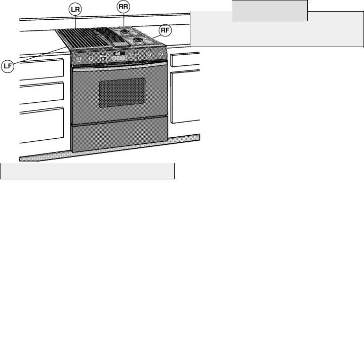
PROPANE CONVERSION
|
|
INCHES |
|
BURNER |
BTU/hr |
DIAMETER |
COLOR |
|
|
|
|
Left Rear (LR) |
8,000 |
.033 |
Zinc |
|
|
|
|
Left Front (LF) |
8,000 |
.033 |
Zinc |
|
|
|
|
Right Rear (RR) |
8,500 |
.035 |
Green |
|
|
|
|
Right Front (RF) |
8,500 |
.035 |
Green |
-14-
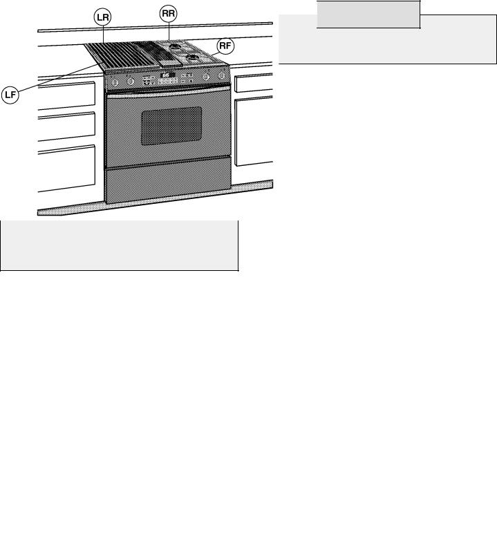
PROPANE GAS (LP) TO NATURAL GAS CONVERSION INSTRUCTIONS
TO CONVERT APPLIANCE FOR USE WITH NATURAL GAS

 WARNING
Natural Gas conversion is to be performed by a JENN-AIR AUTHORIZED SERVICE CONTRACTOR (or other qualified agency) in accordance with the manufacturer’s instructions and all codes and requirements of the authority having jurisdiction. Failure to follow instructions could result in serious injury or property damage. The qualified agency performing this work assumes responsibility for this conversion.
Natural gas supply line must have a natural gas service regulator. Inlet pressure to this appliance should be reduced to a maximum of 14 inches water column (0.5 pounds per square inch (P.S.I.) liquified petroleum (L.P.)/propane gas supply line must have a L.P. gas pressure regulator. Inlet pressure to this appliance should be reduced to a maximum of 14 inches water column (0.5 P.S.I.). Inlet pressures in excess of 0.5 P.S.I. can damage the appliance pressure regulator and other gas components in this appliance and can result in a gas leak.
Manifold - Natural Gas pressure required - 5 Water Column.
Incoming Natural Gas pressure required to regulator - 6 - 7 Water Column.

 WARNING
ELECTRICAL POWER AND GAS MUST BE TURNED OFF PRIOR TO CONVERSION.
1.Replace all orifice hoods . . . Perform step 1 through 4 on pages 12 & 13. Locate the (4) four Natural Gas hoods (with small numbers stamped on their sides) saved from original Natural Gas model. The two hoods with .0520 (#55 orifice) stamped on them are for the left front and left rear burners. The two hoods with the .0595 (#53 orifice) stamped on them are for the two right burners.
To make these conversion adjustments follow the instructions and illustrations (“A” through “D”) on pages 13 and 14.
2.Invert cap in pressure regulator (see illustration “A”). With the appliance installed, the regulator is located on the center underside of the appliance at the inlet to the gas manifold. Identify the type of regulator on the unit and follow the instructions in the appropriate illustration.
3.Adjust low flame setting for each burner. Follow the instructions for burner low flame adjustment on page 14 to increase the simmer flame size.
Natural Gas input required - 36,000 BTU/hr.
|
|
INCHES |
|
BURNER |
BTU/hr |
DIAMETER |
COLOR |
|
|
|
|
Left Rear (LR) |
8,000 |
.0520 |
Brass |
|
|
|
|
Left Front (LF) |
8,000 |
.0520 |
Brass |
|
|
|
|
Right Rear (RR) |
10,000 |
.0595 |
Brass |
|
|
|
|
Right Front (RF) |
10,000 |
.0595 |
Brass |
-15-
 Loading...