


JDS8850BDS
Printed in USA ©2005 Maytag Corporation 8101P698-60
INST
ALLER: Leave these instructions with the appliance./INST
ALLA
TEUR : Laissez ces instructions avec l’appareil./
INSTALADOR: Deje estas instrucciones con el electrodoméstico.
Jenn-Air Dual Fuel
Updraft Slide-In Range
Installation Instructions/Instructions d’installation/Instrucciones de Instalación.
Cuisinière encastrable à deux énergies à circulation ascendante Jenn-Air/
Estufa deslizante de doble combustible de corriente ascendente Jenn-Air
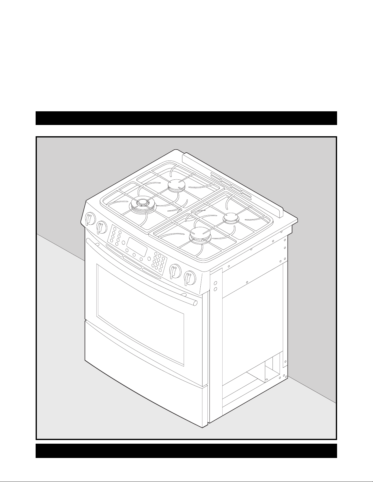
Jenn-Air Dual Fuel Updraft Slide-In Range
INSTALLATION INSTRUCTIONS
PLEASE KEEP THIS MANUAL FOR FUTURE REFERENCE
This manual is intended to assist in the initial installation and adjustments of the range.
• Only qualified personnel should install or service this range.
• Read “Safety Instructions” in Use & Care book before using range.
•
Improper installation, adjustment, alteration, service, maintenance or use of range
can result in serious injury or property damage.
• Installer, take care not to damage flooring.
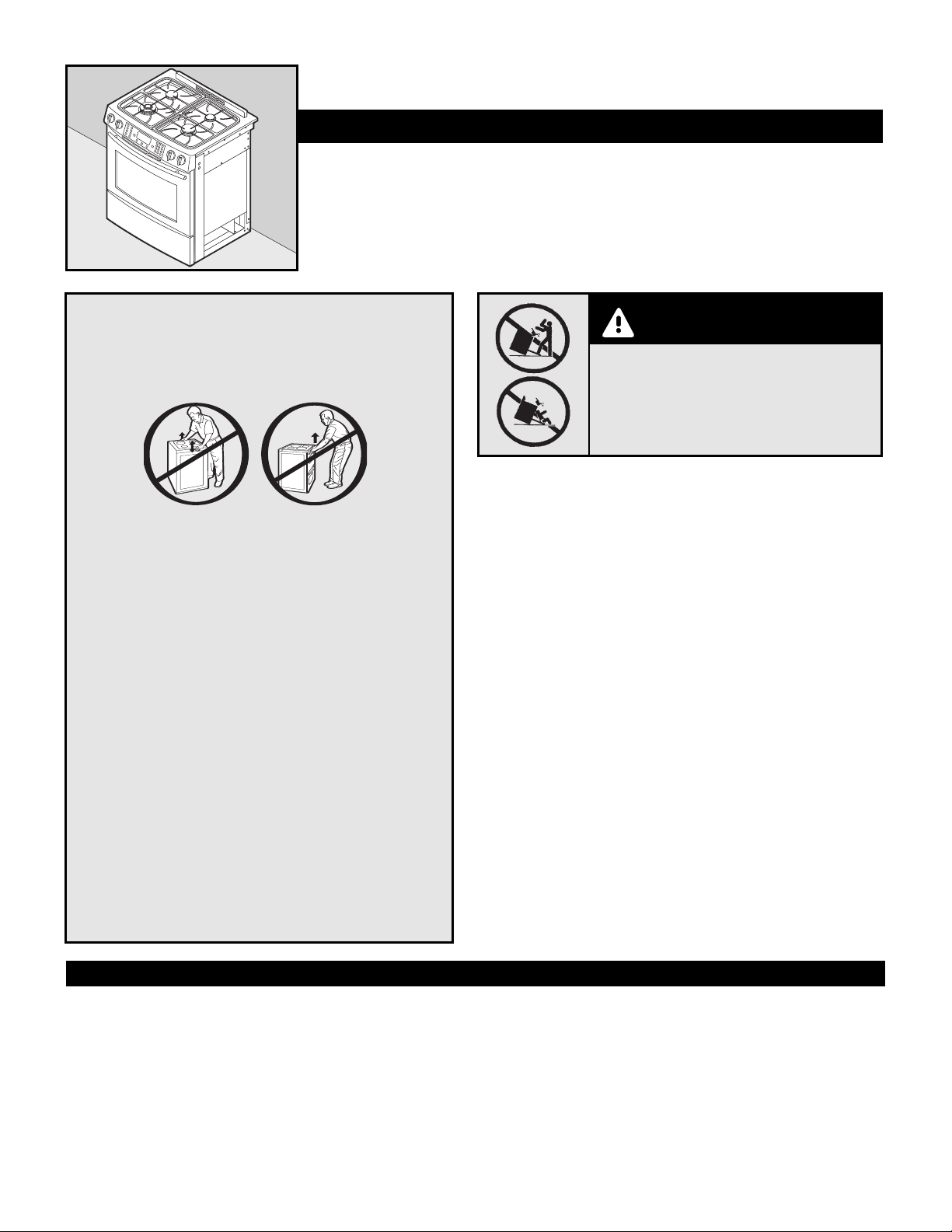
Do not lift or move range by grasping door handles, main
top, or backguard.
This range has been designed in accordance with the
requirements of various safety agencies and complies
with the maximum allowable wood cabinet
temperatures of 194˚F. If this range is installed with
cabinets that have a lower working temperature than
194˚F, discoloration, delamination or melting may occur.
Place range in a well lit area. Do not set range over
holes in the floor or other locations where it may be
subject to strong drafts. Any opening in the wall behind
the range and in the floor under the range should be
sealed. Make sure the flow of cooling/ventilation air is
not obstructed below the range. Note: A range should
NOT be installed over kitchen carpeting.
High Altitude Notice: The specified gas burner ratings
typically apply to elev
ations up to 2000 feet. For higher
altitudes, the rates may need to be reduced to achieve
satisfactor
y oper
ation. A local certified gas servicer will
be able to advise if a reduction is necessary.
A risk of range tip-over exists if the appliance is not installed in accordance with the
provided installation instructions. The proper use of the ANTI-TIP device minimizes
the risk of TIP-OVER. In using this device the consumer must still observe the safety
precautions as stated in the USE and CARE MANUAL and avoid using the oven doors
as a step stool. Installation instructions are provided for wood and cement in either
floor or wall. Any other type of construction may require special installation
techniques as deemed necessary to provide adequate fastening of the ANTI-TIP
bracket to the floor or wall. The bracket may be installed to engage the LEFT or
RIGHT rear leveling foot. NOTE: The bracket provided is designed for use with flush
mount and non-flush mount outlet receptacles. Install the bracket with the
orientation hole in the longer leg against the wall or floor as shown in steps 14-19.
MOBILE HOMES
The installation of a range designed for mobile home installation must conform with
the Manufactured Home Construction and Safety Standard, Title 24 CFR, Part 3280
(formerly the Federal Standard for Mobile Home Construction and Safety,Title 24
HUD, Part 280) or,when such standard is not applicable, the Standard for Manufactured
Home Installations ANSI A225.1/NFPA 501A, or with local codes. In Canada the range
must be installed in accordance with the current CSA Standard C22.1 - Canadian
Electrical Code Part 1 and Section Z240.4.1 - Installation Requirements for Gas
Bur
ning
Appliances in Mobil Homes (CSA Standar
d CAN/CSA - Z240MH).
RECREATIONAL PARK TRAILERS
The installation of a r
ange designed for r
ecr
eational park tr
ailers must confor
m with
state or other codes or
,
in the absence of such codes, with the Standard for
Recr
eational Park Trailers, ANSI A119.5-latest edition. In Canada the range must be
installed in accordance with CAN/CSA - Z240.6.2 - Electrical Requirements for R.V.’s
(CSA Standard CAN/CSA - Z240 RV Series) and Section Z240.4.2 - Installation
Requirements for Propane Appliances and Equipment in R.V.’s (CSA Standard
CAN/CSA - Z240 RV Series).
WARNING
CAUTIONS
• All RANGES CAN TIP AND CAUSE INJURIES
TO PERSONS.
• INSTALL ANTI-TIP DEVICES PACKED WITH
RANGE.
•
FOLLOW ALL INSTALLATION INSTRUCTIONS.
CONNECTING THE RANGE
The range must be installed in accordance with Local and National Electric Code
(NEC)
ANSI/NFP
A No. 70-latest edition, or Canadian Electric Code CSA STD.C221
latest edition. See rating plate for total connected KW rating.
Y
our local utility company will tell you whether the pr
esent electric ser
vice to your
home is adequate
. It may be necessar
y to incr
ease the size of the wiring to the
house and service switch to take care of the electrical load demanded by the range.
The kilowatt rating for the range is specified on the rating plate located on flip-up
plate at the rear center of backguard.
Most local Building Regulations and Codes require that all electrical wiring be done by
licensed electricians.
All wiring should confor
m to Local and National Electrical Codes.
This range requires a single phase three wire 120/240 or a 120/208 volt, 60 Hz,AC
circuit. Wiring codes require a separate circuit be run from the main entrance panel to
the range and that it be equipped with separate disconnect switch and fuses, either in
the main entrance panel or in a separate switch and fuse box.
The electrical connection to this unit is designed only for use with a fle
xible po
wer cor
d. All
units are shipped with a specially designed 4-wire service cord. This cord should be used on
CONNECTING THE RANGE (cont.)
Gas Supply
Installation of this range must conform with local codes or, in the absence of
local codes, with the National Fuel Gas Code,ANSI Z223.1-latest edition. In
Canada the range must be installed in accordance with the current CGA
Standard CAN/CGA-B149 - Installation Codes for Gas Burning Appliances and
Equipment and/or local codes.
A QUALIFIED SERVICEMAN OR GAS APPLIANCE INSTALLER MUST
MAKE THE GAS SUPPLY CONNECTION. Leak testing of the appliance
shall be conducted by the installer according to the instructions
given in step 6.
Apply a non-corrosive leak detection fluid to all joints and fittings in the gas
connection between the supply line shut-off valve and the range. Include gas
fittings and joints in the range if connections were disturbed during installation.
Check for leaks! Bubbles appearing around fittings and connections will
indicate a leak. If a leak appears, turn off supply line gas shut-off valve, tighten
connections, turn on the supply line gas shut off valve, and retest for leaks.
CAUTION: NEVER CHECK FOR LEAKS WITH A FLAME. WHEN LEAK
CHECK IS COMPLETE, WIPE OFF ALL RESIDUE.
NATURAL GAS SUPPLY LINE MUST HAVE A NATURAL GAS SERVICE REGULATOR.
INLET PRESSURE TO THIS APPLIANCE SHOULD BE REDUCED TO A MAXIMUM OF
14 INCHES WATER COLUMN (0.5 POUNDS PER SQUARE INCH (P.S.I.) LIQUEFIED
PETROLEUM (L.P.)/PROPANE GAS SUPPLY LINE MUST HAVE A L.P. GAS
PRESSURE REGULATOR. INLET PRESSURE TO THIS APPLIANCE SHOULD BE
REDUCED TO A MAXIMUM OF 14 INCHES WATER COLUMN (0.5 P.S.I.). INLET
PRESSURES IN EXCESS OF 0.5 P.S.I. CAN DAMAGE THE APPLIANCE PRESSURE
REGULATOR AND OTHER GAS COMPONENTS IN THIS APPLIANCE AND CAN
RESULT IN A GAS LEAK.
Gas supply pressure for testing regulator must be at least 1” water
column pressure above manifold pressure shown on serial plate.
GAS SUPPLY CONNECTION
Follow these procedures to remove appliance for servicing:
1. Slide range forward to disengage range from the anti-tip bracket.
2. Shut off gas supply to appliance.
3. Disconnect electrical supply to appliance
, if equipped.
4. Disconnect gas supply tubing to appliance.
5. Reverse procedure to reinstall. If gas line has been disconnected,
c
hec
k for gas leaks after r
econnection.
6.
T
o prevent range from accidentally tipping, range must be secured to the floor by sliding rear leveling leg into the anti-tip bracket.
NO
TE:
A qualified ser
vicer should disconnect and r
econnect the gas supply
.
The ser
vicer MUST follow installation instructions provided with the gas appliance connector
and the w
ar
ning label attac
hed to the connector
.
HOW TO REMOVE RANGE FOR SERVICING
SERVICE-PARTS INFORMATION
When your range requires service or replacement parts, contact your dealer or authorized service agency. Please give the complete model and serial number of the
range which is located on flip-up plate at the rear of upper left-hand corner or center of backguard.
Your range may not be equipped with some of the features referred to in this manual.
all new branch circuits, mobile homes and when local codes prohibit grounding through
the neutral. For a 3-wire cord replacement, service kit P/N 74011285 must be used.
In The Commonwealth Of Massachusetts
This product must be installed by a licensed plumber or gas fitter when installed
within the Commonwealth of Massachusetts. A “T” handle type manual gas
valve must be installed in the gas supply line to this appliance. A flexible gas
connector, when used, must not exceed a length of three (3) feet / 36 inches.
Check Pressure of House Piping System
1. The appliance and its individual shutoff valve must be disconnected from
the gas supply piping system during any pressure testing of that system at
test pressures in excess of 1/2 lbs./sq. in. (3.5 kPa) (13.8 in. water column).
2. The appliance must be isolated from the gas supply piping system by
closing its individual manual shutoff valve during any pressure testing of
the gas supply piping system at test pressures equal to or less than 1/2
lbs./sq. in. (3.5 kPa) (13.8 in. water column).
A GAS SHUT-OFF VALVE SHOULD BE PUT IN AN ACCESSIBLE LOCATION IN THE
SUPPLY LINE AHEAD OF THE RANGE, FOR TURNING ON AND TURNING OFF GAS
SUPPLY. Range is to be connected to house piping with flexible metal connectors
for gas appliances. CONNECTOR NUTS MUST NOT BE CONNECTED DIRECTLY TO
PIPE THREADS. THE CONNECTORS MUST BE INSTALLED WITH ADAPTORS PROVIDED
WITH THE CONNECTOR.
The house piping and/or range connector used to connect the range to the main gas
supply must be clean, free of metal shavings, rust, dirt and liquids (oil or water). Dirt,
etc. in the supply lines can work its way into the range manifold and in turn cause
failure of the gas valves or controls and clog burners and/or pilot orifices.
Always use a new flexible connector. Do not use existing flexible connector.
Gas leaks may occur in your system and result in a dangerous situation. Gas
leaks may not be detected by smell alone. Gas suppliers recommend you
purchase and install an UL approved gas detector. Install and use in
accordance with manufacturer’s instructions.
NOTE: It is recommended to use a CSA certified flexible connector no longer than 36” (91.4 cm) with a minimum BTU/HR rating of 88,200.
DISCONNECT ELECTRICAL SUPPLY BEFORE SERVICING
THE APPLIANCE.
WARNING
W ARNING
Cuisinière encastrable à deux énergies à circulation ascendante Jenn-Air
INSTRUCTIONS D’INSTALLATION
VEUILLEZ CONSERVER CE MANUEL POUR CONSULTATION ULTÉRIEURE
C
e manuel est prévu pour vous aider dans l’installation et les réglages de la cuisinière.
• Seul du personnel qualifié doit installer ou faire l’entretien de cette cuisinière.
• Lisez les « Instructions de sécurité » dans le guide d’utilisation et d’entretien avant d’utiliser la cuisinière.
• Une installation, des réglages, des modifications, une utilisation ou un entretien, effectués de façon
inappropriée, peuvent entraîner de graves blessures ou des dégâts matériels.
• Installateur : Faites attention de ne pas endommager le sol.
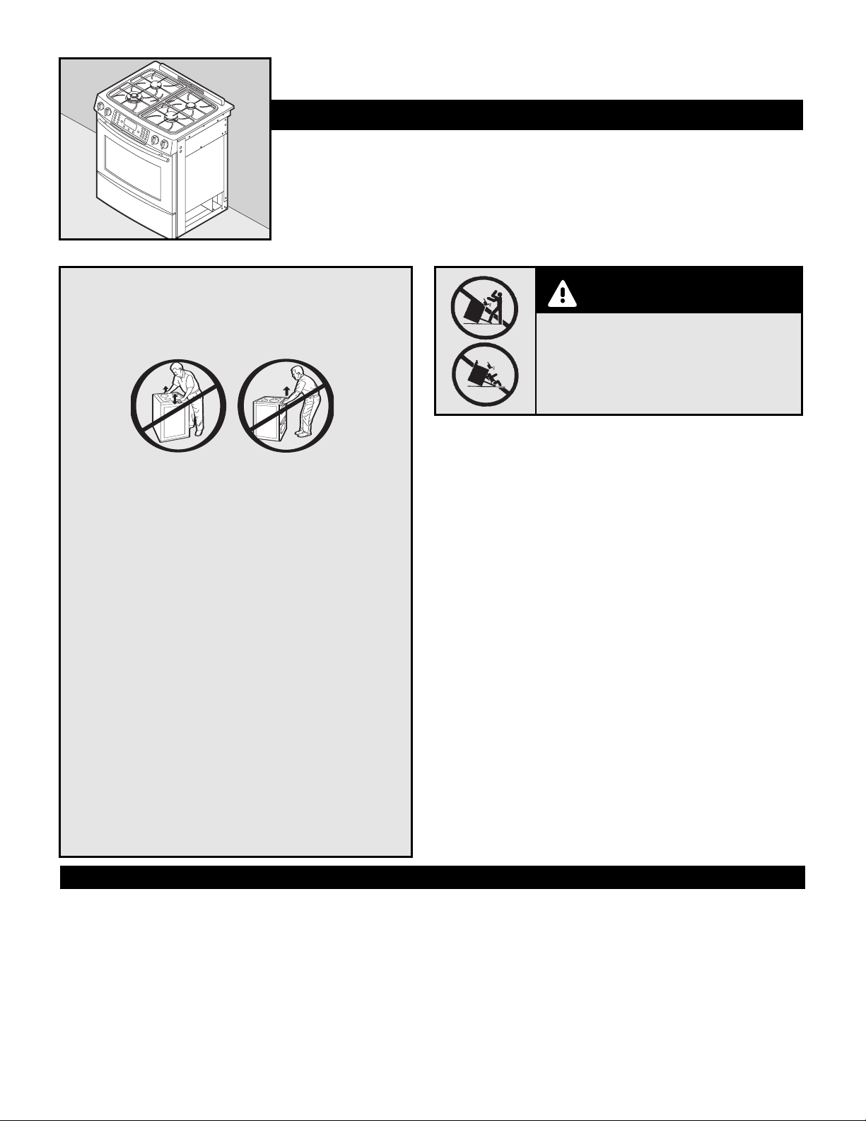
Ne soulevez pas et ne déplacez pas la cuisinière en la
prenant par la poignée de la porte, le dessus ou le dosseret.
Cette cuisinièr
e a été conçue conformément aux exigences de
diverses agences concernées par la sécurité et respecte les
températures maximales permises de 90 °C (194 °F) pour les
armoir
es en bois. Si cette cuisinière est installée près
d’armoires ne supportant qu’une température inférieure à 90 °C
(194 °F), il y a risque de décoloration, délamination ou fusion.
Placez la cuisinière dans un endroit bien éclairé. Ne l’installez
pas au-dessus de trous dans le plancher ou à d’autres endroits
où elle risque d’être soumise à de forts courants d’air. Toute
ouverture dans le mur derrière la cuisinière et dans le sol sous
la cuisinièr
e doit être fermée hermétiquement. Assurez-vous
que la circulation de l’air de refroidissement/ventilation n’est
pas entravée sous la cuisinière. REMARQUE : N’installez PAS
une cuisinière sur de la moquette de cuisine.
A
vis pour altitude élevée :
Les car
actéristiques nominales
des brûleurs à gaz précisées sont prévues pour des altitudes
de 610 m (2 000 pieds) max. À des altitudes plus importantes,
ces v
aleurs peuvent avoir à être réduites pour obtenir un
résultat satisfaisant. Un réparateur/installateur certifié pour
le gaz sera en mesure de vous indiquer si cela est nécessaire.
AVERTISSEMENT
ATTENTION
• TOUTES LES CUISINIÈRES PEUVENT SE
RENVERSER ET BLESSER.
• INSTALLEZ DES DISPOSITIFS ANTIRENVERSEMENT
FOURNIS AVEC LA CUISINIÈRE.
•
SUIVEZ TOUTES LES INSTRUCTIONS
D’INSTALLATION.
RACCORDEMENT À LA CUISINIÉRE
La cuisinière doit être installée conformément au National Electrical Code (NEC)
ANSI/NFP
A nº 70 – édition la plus récente
, ou conforme au Code canadien de
l’électricité, norme CSA C22.1, édition la plus récente. Voyez sur la plaque signalétique
la puissance nominale totale en kW.
Votre compagnie d’électricité locale vous indiquera si l’alimentation électrique actuelle
de votre résidence est suffisante. Il pourra être nécessaire d’augmenter le calibre du
câblage et de l’interrupteur secteur pour satisfaire la consommation en électricité de la
cuisinière. La puissance nominale en kilowatts de la cuisinière est précisée sur la plaque
signalétique située sur une plaque escamotable à l’arrièr
e
,
au centr
e du dosseret.
Certains modèles sont livrés directement de l’usine avec un cordon d’alimentation.
Aucun r
accor
dement n’est nécessair
e sur ces modèles. Il suffit de br
anc
her le cor
don
dans la prise murale. Sur les modèles sans cordon, le raccordement à l’alimentation est
nécessaire conformément aux codes locaux. Il est possible d’utiliser soit un conduit soit un
cor
don souple
. Avec un cordon souple, pour cuisinières, ne l’utilisez qu’avec des cosses
fermées prévues soit pour 240 volts, 40 A, soit pour 240 volts, 50 A - ouverture de 34,94
mm (1-3/8 po) de diamètre. Un cordon à 4 conducteurs doit être utilisé sur les nouvelles
installations à cir
cuit de dériv
ation (NEC 1996),
de maisons mobiles,
de véhicules récréatifs et
là où les codes locaux interdisent la mise à la terre par le neutre. Une alimentation à 3 fils peut
être utilisée là où elle est autorisée par les codes locaux. Lorsqu’un cordon d’alimentation est
utilisé, celui-ci ne doit pas dépasser 1,20 m (4 pieds) en longueur.
Le r
accor
dement électrique de cet appar
eil est conçu pour être utilisé seulement avec un
cor
don d’alimentation souple. Tous les appareils sont livrés avec un cordon à 4 fils de
conception spéciale. Ce cordon doit être utilisé sur tous les nouveaux circuits de dérivation,
Un risque que la cuisinière se renverse existe si l’appareil n’est pas installé conformément
aux instructions d’installation fournies. L’utilisation correcte du dispositif
ANTIRENVERSEMENT minimise le risque de RENVERSEMENT. Même avec ce dispositif,
le consommateur doit toujours observer les mesures de sécurité précisées dans le
MANUEL D’UTILISATION ET D’ENTRETIEN et éviter de monter sur les portes des fours.
Les instructions d’installation sont fournies pour des endroits où les murs et les sols
sont en bois ou en ciment. Tout autre type de construction peut nécessiter des
techniques d’installation spéciales, pour permettre la fixation du support
ANTIRENVERSEMENT au mur ou au sol. La bride doit être installée afin de retenir le
pied ARRIÈRE GAUCHE ou DROIT. REMARQUE : La bride fournie est conçue pour être
utilisée avec des prises montées ou non en affleurement. Installez la bride en mettant
le trou d’orientation de l’aile la plus longue de la bride contre le mur ou le plancher,
comme l’illustrent les étapes 14 à 19.
MAISONS MOBILES
L’installation d’une cuisinière conçue pour une maison mobile doit être conforme à la
Manufactured Home Construction and Safety Standard (norme de sécurité et de
construction des résidences préfabriquées), titre 24 CFR, partie 3280 (antérieurement,
la Federal Standard for Mobile Home Construction and Safety, titre 24 HUD, partie 280)
ou, lorsqu’une telle norme n’est pas applicable, à la norme pour les installations de
résidences préfabriquées ANSI A225.1/NFPA 501A, ou conformément aux codes locaux.
Au Canada, la cuisinière doit être installée selon la norme courante CSA C22.1 - Code
canadien de l’électricité, partie 1 et section Z240.4.1 – exigences d’installation pour
appareils à gaz des maisons mobiles : (norme CSA CAN/CSA - Z240MH).
MAISONS MOBILES POUR P
ARC
RÉCRÉA
TIF
L
’installation d’une cuisinièr
e conçue pour les maisons mobiles de par
c récréatif doit
êtr
e confor
me aux règlements de l’état ou à d’autr
es codes,
ou en l’absence de tels
codes,
confor
me à la nor
me Standar
d for Recreational Park Trailers, (norme pour
maisons mobiles de par
c récréatif)
ANSI
A119.5, édition la plus récente. Au Canada,
la cuisinièr
e doit êtr
e installée selon CAN/CSA Z240.6.2 - e
xigences électriques
pour véhicules récréatifs (nor
me CSA CAN/CSA – Z240 séries
VR) et section
Z240.4.2 – e
xigences d’installation pour équipement et appar
eils au propane dans
véhicules récréatifs (nor
me CSA CAN/CSA – Z240 séries
VR).
 Loading...