

Page 1
d.SIGN
IPS
®
Instructions for Use
Page 2
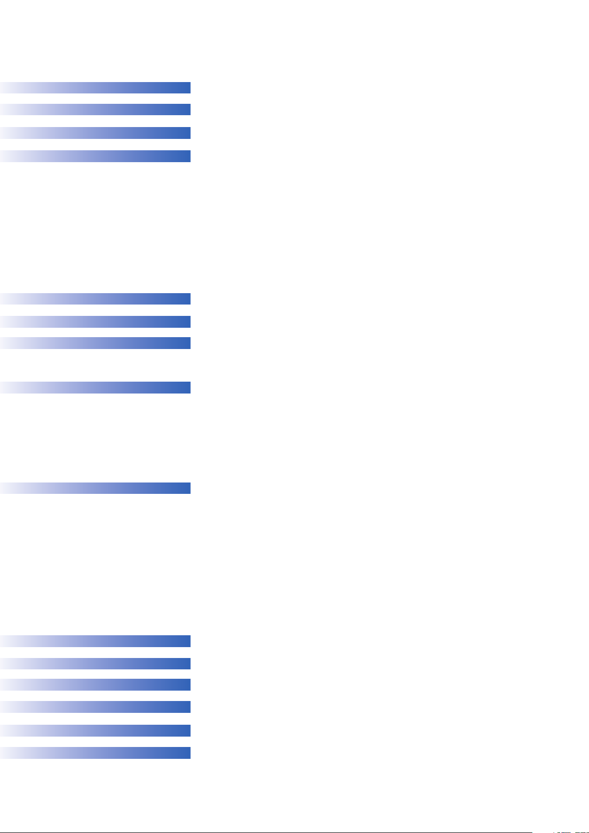
Table of Contents
3 IPS d.SIGN
6 Composition
7 IPS d.SIGN – Product overview
8 IPS d.SIGN – Description of the assortments
8 IPS d.SIGN Basic Kits
10 IPS d.SIGN Trial Kit
11 IPS d.SIGN Deep Dentin Kits
12 IPS d.SIGN Margin Kits
13 IPS d.SIGN Bleach Kit
14 IPS d.SIGN Impulse 1 Kit
15 IPS d.SIGN Impulse 2 Kit
16 IPS d.SIGN Gingiva Kit
1
6 IPS d.SIGN Essence Kit
17 IPS d.SIGN Stains Kit
17 IPS d.SIGN Shade Kit
IPS d.SIGN – Liquids
18
20 IPS d.SIGN – Shade selection
21 IPS d.SIGN – Layering diagrams
21 IPS d.SIGN Chromascop layering diagram
22 IPS d.SIGN A–D layering diagram
I
2
2
24 Functional support of the veneering ceramic
25 Framework design for ceramic shoulders
25 Framework stability
26 Framework design for bridges
27 Design of bridge pontics
27 Interface between metal and ceramic
28
28 Starting situation
28 Fabricating the framework
30 Oxide firing
32 1
33
34 1
36 2
37 1
41 2
42 Preparing the restoration for glaze firing
43
45
PS d.SIGN – Framework design
3
Alloys
3
d.SIGN – Instructions for Use
IPS
st
opaquer firing
nd
2
opaquer fi
st
shoulder firing
nd
shoulder firing
st
dentin and incisal firing
nd
dentin and incisal firing
Stain and char
ring
Glaze fi
ring
acterization firing
47
IPS d.SIGN – Corrective firings (Add-on)
48 Correct use of IPS d.SIGN Cervical Dentin D2/D3
49 IPS d.SIGN –
50 Feel the difference – feel IPS d.SIGN
52 A look over the shoulder
62 IPS d.SIGN –
Chromascop
62
A–D
64
66 Independent of any shade system
Firing parameters
Materials combination tables
2
Page 3
d.SIGN
IPS
®
The requirements for functionality and
esthetic appearance of ceramic restorations
a
re continuously rising. To meet these requi-
a
rements manufacturers are faced with the
challenge of developing materials that satisfy
the needs of experienced ceramists, by
ffering them a multitude of design
o
possibilities, and less experienced users by
enabling them to have a successful start in
the field of porcelain-fused-to-metal
restorations. In order to give a high end
eramic the ease of handling that customers
c
expect, the range of indications of IPS d.SIGN
was given top priority during the
development phase.
With a well designed basic assortment and
the various additional assortments of
IPS d.SIGN, beginners and specialists alike
will have all the materials they need to
restore lost tooth structure in a true-tonature, highly aesthetic fashion. IPS d.SIGN is
a material suitable for basic types of restorations, as well as restorations having
sophisticated morphological structures. In
this way, all the demands placed on the
material prior to its development have been
fully met.
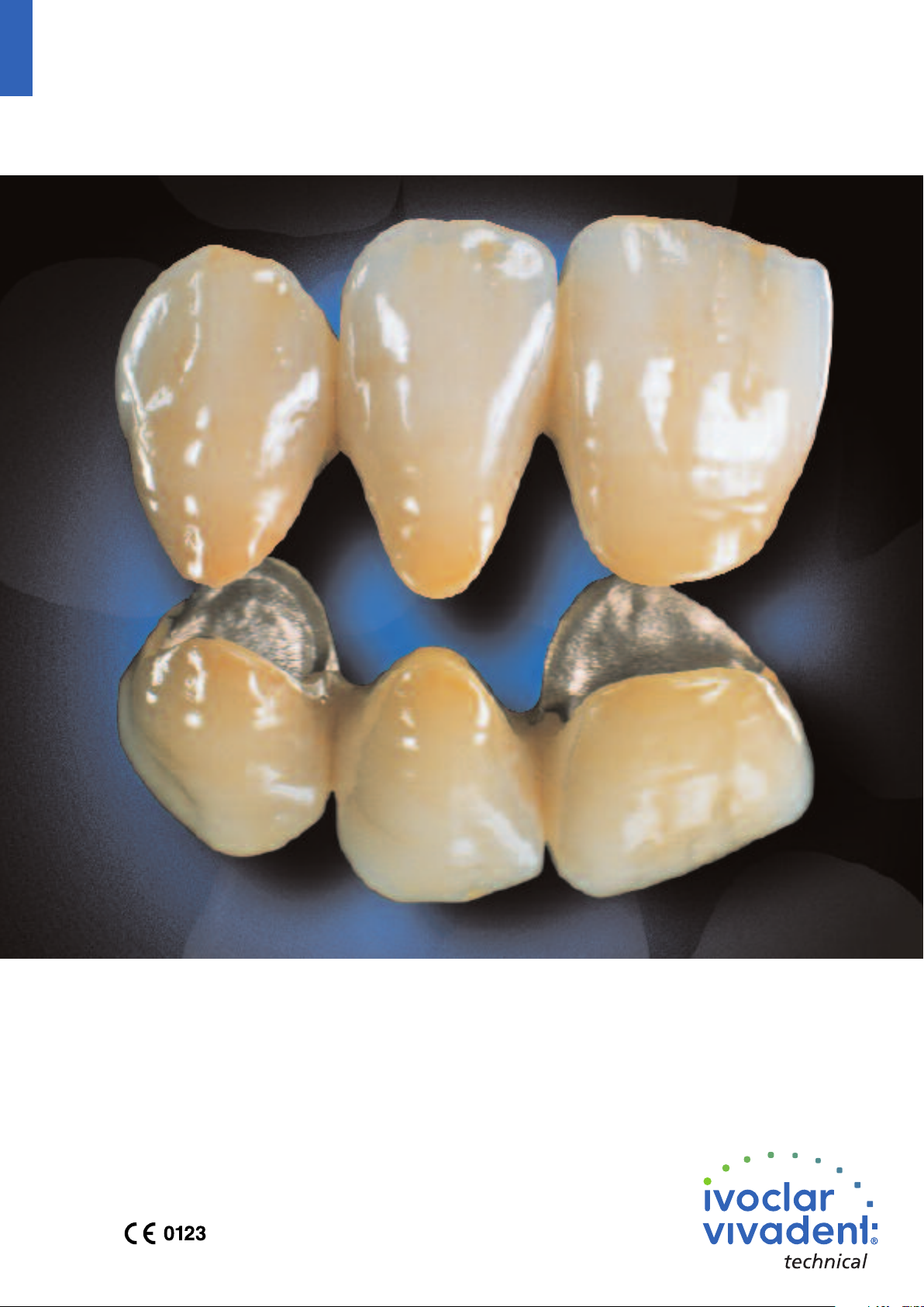
With IPS d.SIGN, highly aesthetic restorations
that are virtually undetectable among their
natural counterparts may be fabricated by
easy, efficient layering of the material.
Moreover, expert ceramists are provided with
a comprehensive range of additional
materials.
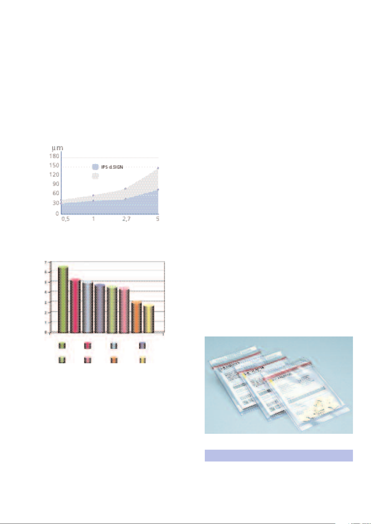
The shades of IPS d.SIGN are based on the
Chromascop and A–D shade guides. Shade
tabs fired from the actual material are
supplied with each assortment.
Fluorapatite leucite glassceramic
PS d.SIGN fluorapatite leucite glass-ceramic
I
has been developed taking nature as the
standard, with the most important properties
of natural teeth serving as models. The main
norganic component of a natural tooth are
i
apatite crystals, in which hydroxyl and sometimes carbonate groups are embedded. In
addition to this composition, IPS d.SIGN
fluorapatite glass-ceramics also contains
uoride ions that provide the material with a
fl
very high chemical resistance. Moreover, the
above mentioned compositions results in
IPS d.SIGN demonstrating exceptional optical
properties, which is yet another distinct
advantage of this new type of glass-ceramic
material. Increased brightness and brilliance,
clearly enhanced stability of shade, and trueto-nature fluorescence are the results of
these development efforts.
SEM – Conventional feldspar cer
amic
Comprehensive Treatment
System
Ivoclar V
comprehensive treatment system that
consists of the following components:
– Alloys
– Veneering ceramic
– Cementation system
This system was developed with the objective
that all of the materials should be coordinated with each other so that optimum results
are achieved. The IPS d.SIGN fluorapatite
leucite ceramic is an innovative ceramic
material that of
and application. These properties of
IPS d.SIGN are based on its new material
specifications. What does that means in
practical work?
ivadent pr
ovides you with a
fers new ways of pr
ocessing
al tooth
SEM – Natur
SEM (after surface etching) – IPS d.SIGN
3
Page 4
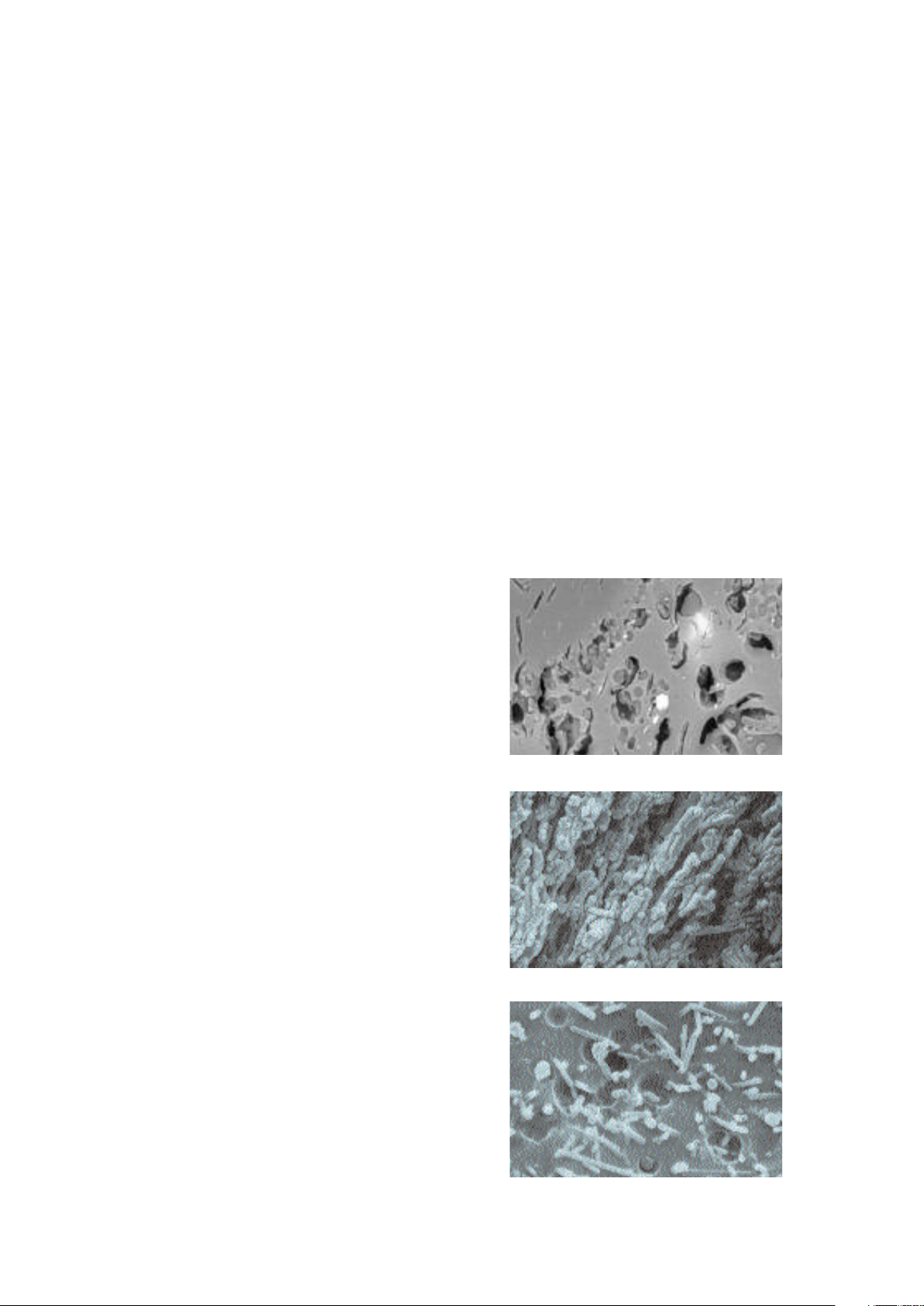
Another property that this new type of
urface structure exhibits is excellent
s
olishability and limited abrasion to opposing
p
natural tooth structure. The IPS d.SIGN
materials demonstrate outstanding stability
and are fired at temperatures below
00 °C/1652 °F.
9
Feldspar ceramic
n vitro-equivalent years
I
Alloys
Each metal supported restoration starts with
the fabrication of a metal framework. For
hat purpose, various IPS d.SIGN alloys are
t
available. The IPS d.SIGN alloy selection
ranges from high gold alloys and goldreduced alloys to base metal alloys. These
alloys meet the international requirements of
SA and ADA and were developed in
I
combination with IPS d.SIGN.
The coefficient of thermal expansion (CTE) is
a significant parameter for dental materials.
t is vitally important to ensure the thermal
I
compatibility between alloy and ceramic
material. In the 25–500 °C temperature
range, the CTE values of the IPS d.SIGN
alloys range between 13.8 and
14.8 x 10
composition. The coefficient of thermal
expansion of the IPS d.SIGN ceramic is
12.0–12.6 x 10
-6K-1
, depending on the alloy's
6
1
-
-
K
.
Vertical abrasion to the enamel of the antagonist.
Internal investigation, R&D Ivoclar Vivadent AG (1998)
Abrasion to antagonist enamel
2
mm
Ceramic A
Ceramic E
This bar diagram depicts the abrasion to antagonist enamel compared to other
amic materials
dental cer
Sorensen,
A.
John
Ceramic B Ceramic C Ceramic D
Enamel IPS
DMD
.
PhD (1999)
,
Ceramic F
d.SIGN
The IPS d.SIGN alloys
– IPS d.SIGN 98 (high gold)
– IPS d.SIGN 96 (high gold)
– IPS d.SIGN 91 (gold-reduced)
– IPS d.SIGN 84 (palladium-based)
– IPS d.SIGN 67 (palladium-based)
– IPS d.SIGN 59 (palladium-based)
– IPS d.SIGN 53 (palladium-based)
– IPS d.SIGN 30 (chrome-cobalt)
– IPS d.SIGN 15 (nickel-chrome)
The compatibility of the IPS d.SIGN ceramic
and IPS d.SIGN alloys was thor
oughly tested.
When using other alloys, please ask your
alloy manufacturer if they are compatible
with IPS d.SIGN ceramic.
The product range may vary from country to country.
4
Page 5
Cementation
Variolink
®
Esthetic Resin Cements
Multilink
®
Universal Resin Cement
Vivaglass®CEM
Glass ionomer Cement
C
ement
Variolink®Veneer Variolink®II Multilink®Automix Vivaglass®CEM PL
C
uring Mode Light-cure Light/Dual-cure Dual-cure Self-cure
Cementation Method Adhesive: Adhesive: Adhesive: Conventional
Syntac or Excite Syntac or Excite DSC Multilink Primer A/B
total-etch total-etch self-etch
IPS d.SIGN
––
33
Select an appropriate cementation material
rom the Ivoclar Vivadent range of products.
f
ybrid ionomer and glass ionomer cements
H
(Vivaglass
for conventional cementation and offer a
number of advantages such as:
–
– High translucency
– High radiopacity
– Continuous fluoride release
– Aesthetic advantages for ceramic
– Minimum solubility
®
CEM), for example, are suitable
Low expansion
houlders
s
Please observe the corresponding Instructions for Use
3 recommended product combination
– not recommended/combination impossible
5
Page 6

Indication
– Metal-ceramic veneers
Veneers on refractory dies
–
Contraindication
– If patients are known to be allergic to any of the ingre-
dients of IPS d.SIGN, the
material should not be used.
Composition
The IPS d.SIGN glass-ceramic materials and liquids
contain the following main components:
– IPS d.SIGN ceramic materials
iO
50–65 wt.%
S
:
2
K
, Na
dditional contents are: Al
A
Li
O, ZrO2and pigments
2
2O3
,
O
2
– Opaquer pastes, Stains, and glazing materials
lso contains 25–40 wt. % glycols
a
, CaO, P
O
2
2O5
F,
,
Important processing
restrictions
– Mixing with other metal-ceramic powders (e.g.
IPS Classic
– Mixing with metal-free veneering ceramic powders (e.g.
IPS Empress
– Use of liquids or separating agents other than the ones
provided with the IPS d.SIGN assortments.
– Mixing of IPS d.SIGN materials in powder form (e.g.
Dentin, Incisal, etc.) with
IPS d.SIGN paste materials (e.g. Shades, Stains).
– Firing of IPS d.SIGN onto incompatible alloys
®
, IPS InLine®)
®
, IPS e.max®)
Important note
– Ceramic furnaces of other manufacturers often feature
opening mechanisms different from that of Ivoclar
Vivadent
furnaces. Therefore, the firing conditions may also differ.
Make sure to take these varying firing conditions into
account when working with IPS d.SIGN.
Warning
– Finishing ceramic restorations results in grinding dust.
Avoid inhalation. Use
suction equipment or protective masks.
– IPS d.SIGN Opaquer Liquid, 15 ml
Components: Polymer, butylene glycol, and glycerine
– IPS d.SIGN Build-Up Liquid, 60 ml and 250 ml
Components: Water, butylene glycol, and additives
– IPS d.SIGN Glaze and Stain Liquid, 15 ml
Components: Butylene glycol
– IPS d.SIGN Margin Build-Up Liquid, 60 ml
Components: Water, cellulose derivative
– IPS Margin Sealer, 20 ml
Components: Wax dissolved in hexane
– IPS Model Sealer, 50 ml
Components: Ethyl acetate, nitro-cellulose, softener
– IPS Ceramic Separating Liquid, 15 ml
Componets: Paraffin oil
6
Page 7

d.SIGN – Product overview
IPS
Opaquer pastes, intensive opaquer pastes, dentin, incisal, transparent,
dd-on, and glazing materials, as well as all the necessary liquids. The Kit also
Basic Kit
a
ontains a materials shade guide for the most popular Chromascop shades.
c
Chromascop
A–D
eep Dentin Kit
D
Margin Kit
Bleach Kit
Basic Kit
Deep Dentin Kit
Margin Kit
Deep dentin materials in the 10 most popular Chromascop shades. They are
M
add-on, and glazing materials, as well as all the necessary liquids. The Kit also
Margin materials in the 8 most popular A-D shades and 4 intensive materials
sed to intensify the chroma in layers of limited thickness.
u
argin materials in the 10 most popular Chromascop shades and 4 intensive
materials for special effects. 1 margin add-on material is used for final
The ultra-light shades enable optimum integration of the r
leached environment. 2 opaquers, 2 margin materials, 4 dentin materials,
b
paquer pastes, intensive opaquer pastes, dentin, incisal, transparent,
O
contains a materials shade guide for the most popular A–D shades.
eep dentin materials in the 7 most popular A-D shades. They are used to
D
for special effects. 1 margin add-on material is used for final adjustment of
djustment of the ceramic shoulder.
a
estoration in a
1 incisal material.
intensify the chroma in layers of limited thickness.
the ceramic shoulder.
Bleach Kit BL
Impulse Kit 1
Impulse Kit 2
Gingiva Kit
Essence Kit
any shade system
Assortments independent of
Stains Kit
Shade Kit
Four accurately coordinated shades meet the highest demands related
15 r
ranging from Mamelon to Opal materials facilitate the application
14 ready-mixed Impulse materials based on the inspiration and philosophies
of renowned experts, such as Enrico Steger, Donald F. Cornell,
5 true-to-natur
each patient situation in combination with the 4 gingival modifiers.
4 ceramic stains in powder form. They may be applied alone or mixed with
14 intensive stains in paste form to r
7 dentin stains in paste form for subsequent shade adjustments
to contemporary “white aesthetics”.
eady-mixed individual fluorapatite leucite ceramic materials
of true-to-nature effects.
and Dr. Robert R. Winter.
e gingival materials that can be individually used for
other materials.
oduce natural characteristics
on the ceramic surface.
of IPS d.SIGN r
epr
estorations.
7
Page 8
d.SIGN – Description of the
IPS
assortments
IPS d.SIGN Basic Kits
d.SIGN Basic Kit A–D
IPS d.SIGN Basic Kit Chromascop
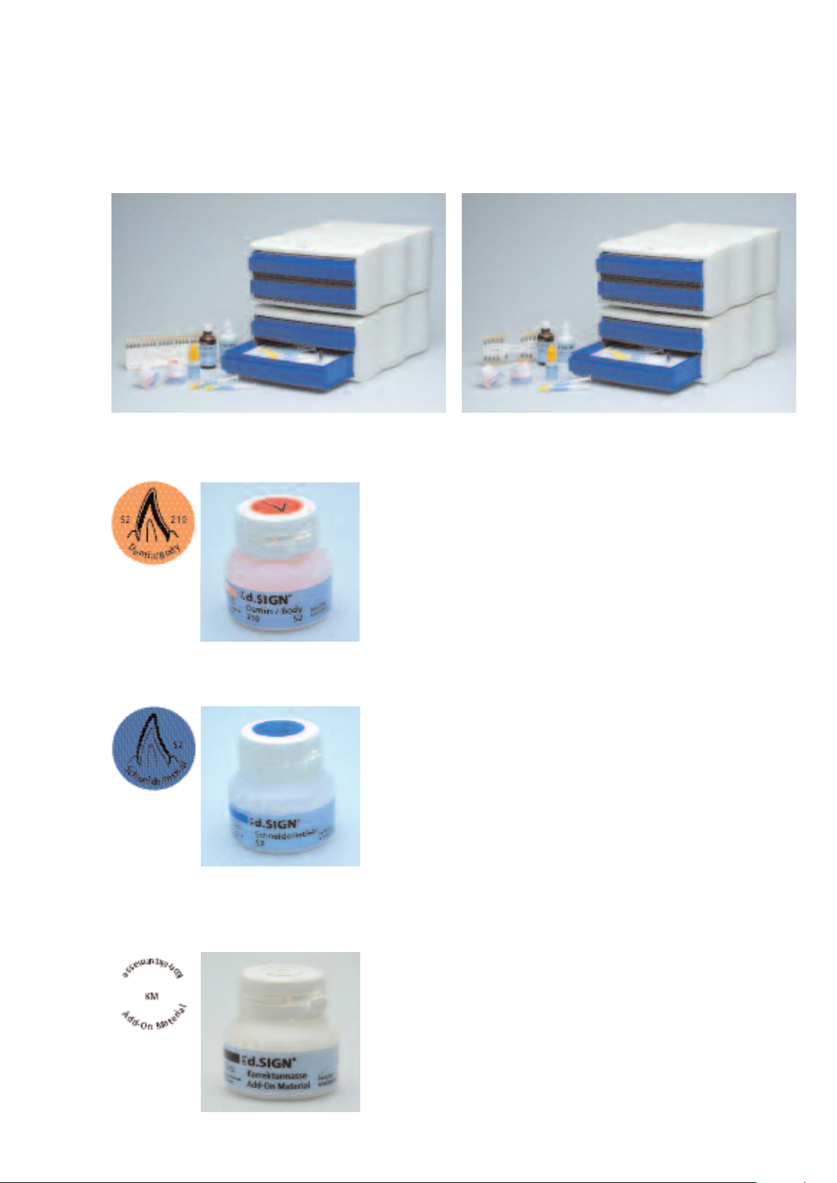
IPS d.SIGN Dentin
IPS
IPS d.SIGN Incisal
The apatite glass-ceramic material is
distinguished for its lifelike appearance.
Apatite is also a component of natural teeth
and supports the light optical properties,
such as translucency, brightness, and light
scattering. Page 48 contains a detailed
description on the use of Cervical Dentin
D2/D3.
The six IPS d.SIGN Incisal materials (S1–S3
and TS1-TS3) demonstrate a shade gradation
similar to that of natural incisal ar
dinated with the
materials ar
Chromascop and the A–D shade guides (see
Materials Combination Tables on page 62 ff).
e coor
eas. The
IPS d.SIGN Add-On
This add-on material with its medium incisal
opacity can be used alone or mixed with
other IPS d.SIGN layering materials. Observe
a mixing ratio of max. 1:1.
8
Page 9
IPS d.SIGN Opaquer
Opaquer pastes in the most
popular shades. The
aterials demonstrate
m
excellent stability and
outstanding masking
capabilities, even when
applied in thin layers (see
lso Material Combination
a
Table on page 62 ff).
Delivery form
Chromascop
IPS d.SIGN Basic Kit
– 10 IPS d.SIGN Opaquers, 3 g each
Shades: 130, 140, 210, 220, 230, 310, 410, 420, 430,
510
– 4 IPS d.SIGN Intensive Opaquers, 3 g each
Shades: white, purple, brown, incisal
– 10 IPS d.SIGN Dentin materials, 20 g each
Shades: 130, 140, 210, 220, 230, 310, 410, 420, 430,
510
– 3 IPS d.SIGN Incisal materials, 20 g each
Gradations: S1, S2, S3
– 1 IPS d.SIGN Transparent material, neutral, 20 g
– 1 IPS d.SIGN Glaze, 3 g
– 1 IPS d.SIGN Add-On material, 20 g
– 1 IPS d.SIGN Opaquer liquid, 15 ml
– 2 IPS d.SIGN Build-up liquid (Medium and Optimum 2),
60 ml
1 IPS d.SIGN Glaze and Stain liquid, 15 ml
–
– 1 IPS Model Sealer, 50 ml
– 1 IPS Ceramic Separating Liquid, 15 ml
– 1 IPS d.SIGN Opaquer material shade guide
– 1 IPS d.SIGN Dentin material shade guide
1 IPS d.SIGN Incisal material shade guide
–
– 1 Chromascop shade guide
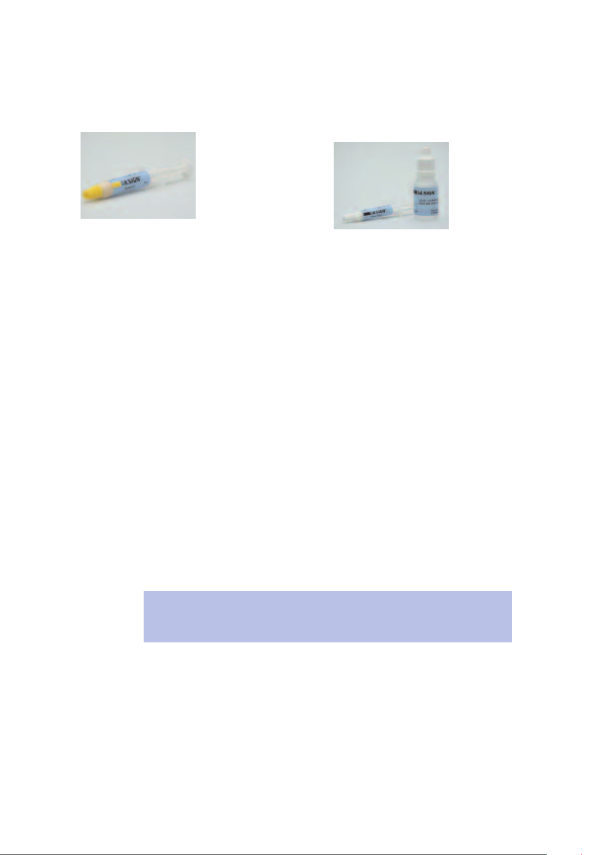
IPS d.SIGN Glaze
PS d.SIGN Glaze and Stain Liquid
I
life-like lustre can be
A
chieved easily and
a
conveniently with IPS d.SIGN
Glaze in combination with
the IPS d.SIGN Glaze and
taine liquid.
S
A–D
IPS d.SIGN Basic Kit
– 8 IPS d.SIGN Opaquers, 3 g each
Shades: A2, A3, A3.5, B2, B3, C3, D2, D3
– 4 IPS d.SIGN Intensive Opaquers, 3 g each
Shades: white, purple, brown, incisal
– 8 IPS d.SIGN Dentin materials, 20 g each
Shades: A2, A3, A3.5, B2, B3, C3, D2, D3
– 1 IPS d.SIGN Cervical Dentin D2/D3
– 3 IPS d.SIGN Incisal materials, 20 g each
Gradations: TS1, TS2, TS3
– 1 IPS d.SIGN Transparent material, neutral, 20 g
– 1 IPS d.SIGN Glaze, 3 g
– 1 IPS d.SIGN Add-on material, 20 g
– 1 IPS d.SIGN Opaquer liquid, 15 ml
– 2 IPS d.SIGN Build-up liquid (Medium and Optimum 2),
60 m
– 1 IPS d.SIGN Glaze and Stain liquid, 15 ml
– 1 IPS Model Sealer, 50 ml
– 1 Ceramic Separating Liquid, 15 ml
1 IPS d.SIGN Opaquer material shade guide A–D
–
– 1 IPS d.SIGN Dentin material shade guide A–D
– 1 IPS d.SIGN Incisal material shade guide A–D
The IPS d.SIGN Basic Kits contain the most popular shades and are suitable for
oducing the most popular basic tooth shades without any difficulties. In this
epr
r
way, rarely used shades do not increase the initial investment but are available as
refills.
Refills
IPS d.SIGN Opaquer, 3 g each
–
Shades: 110, 120, 130, 140, 210, 220, 230, 240, 310,
320, 330, 340, 410, 420, 430, 440, 510, 520, 530, 540
– IPS d.SIGN Opaquer F, 1 g
IPS d.SIGN Dentin material, 20 g each / 100 g each /
–
250 g each; Shades: 110, 120, 130, 140, 210, 220, 230,
240, 310, 320, 330, 340, 410, 420, 430, 440, 510, 520,
530, 540
– IPS d.SIGN Incisal material, 20 g each / 100 g each /
250 g each; Gradations: S1, S2, S3
ent material, neutral, 20 g each /
– IPS d.SIGN T
100 g each / 250 g each
ranspar
Refills
– IPS d.SIGN Opaquer, 3 g each
Shades: A1, A2, A3, A3.5, A4, B1, B2, B3, B4, C1, C2, C3,
C4, D2, D3, D4
–
IPS d.SIGN Opaquer F, 1 g
– IPS d.SIGN Dentin materials, 20 g each / 100 g each /
250 g each; Shades: A1, A2, A3, A3.5, A4, B1, B2, B3, B4,
C1, C2, C3, C4, D2, D3, D4
IPS d.SIGN Cervical Dentin D2/D3
–
– IPS d.SIGN Transparent Incisal material, 20 g each / 100 g
-S3
-S2, T
each / 250 g each; Gradations: T
9
-S1, T
Page 10
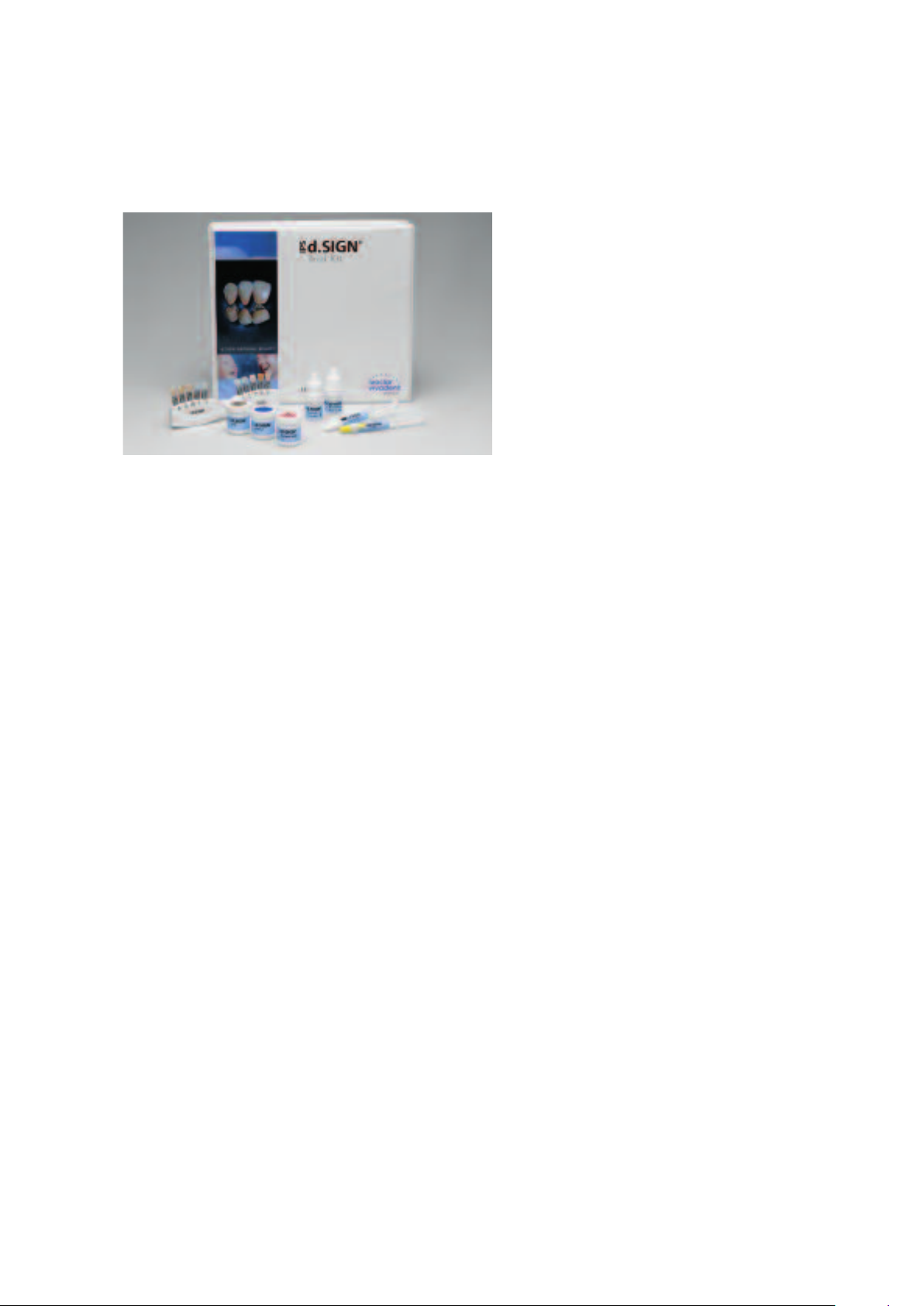
IPS d.SIGN Trial Kit
IPS d.SIGN Trial Kit
Delivery form
Chromascop
IPS d.SIGN Trial Kit
– 1 IPS d.SIGN Opaquer, 3 g; Shade: 210
– 1 IPS d.SIGN Dentin, 3 g; Shade: 210
– 1 IPS d.SIGN Incisal, 3 g; Gradation: S2
– 1 IPS d. SIGN Deep Dentin, 3 g; Shade: 210
– 1 IPS d.SIGN Margin, 3 g; Shade: 210
- 1 IPS d.SIGN Transpa, 3 g; Shade: neutral
– 1 IPS d.SIGN Occlusal Dentin, 3 g; Shade: orange
– 2 IPS d.SIGN Effect, 3 g each; Shades: 1, 3
– 1 IPS d.SIGN Mamelon, 3 g; Shade: light
– 1 IPS d.SIGN Glaze, 3 g
– 1 IPS d.SIGN Build-up liquid Medium, 5 ml
– 1 IPS d.SIGN Glaze and Stain liquid, 5 ml
1 IPS d.SIGN Margin Build-Up liquid, 5 ml
–
– 1 Material shade guide
A–D
IPS d.SIGN Trial Kit
– 1 IPS d.SIGN Opaquer, 3 g; Shade: A33
– 1 IPS d.SIGN Dentin, 3 g; Shade: A3
– 1 IPS d.SIGN Incisal, 3 g; Gradation: TS2
– 1 IPS d. SIGN Deep Dentin, 3 g; Shade: A3
– 1 IPS d.SIGN Margin, 3 g; Shade: A3
- 1 IPS d.SIGN Transpa, 3 g; Farbe: neutral
– 1 IPS d.SIGN Occlusal Dentin, 3 g; Farbe: orange
– 2 IPS d.SIGN Effect, 3 g each; Shades: 1, 3
– 1 IPS d.SIGN Mamelon, 3 g; Shade: light
– 1 IPS d.SIGN Glaze, 3 g
1 IPS d.SIGN Build-Up liquid Medium, 5 ml
–
– 1 IPS d.SIGN Glaze and Stain liquid, 5 ml
– 1 IPS d.SIGN Margin Build-Up liquid, 5 ml
– 1 Material shade guide
10
Page 11
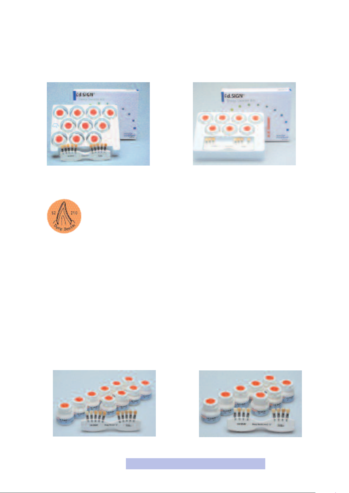
IPS d.SIGN Deep Dentin Kits
IPS d.SIGN Deep Dentin
With the IPS d.SIGN Deep Dentin materials,
restorations that demonstrate true-to-nature
shade effects can be achieved even with
limited layer thicknesses. Particularly if space
is limited, IPS d.SIGN Deep Dentin materials
can be used to intensify the chroma
(see 'Materials Combination Table' on page
62 ff).
IPS d.SIGN Deep Dentin Kit A–DIPS d.SIGN Deep Dentin Kit Chromascop
Delivery form
Chromascop
IPS d.SIGN Deep Dentin Kit
– 10 IPS d.SIGN Deep Dentin materials, 20 g each
Shades: 130, 140, 210, 220, 230, 310, 410, 420, 430, 510
– 1 IPS d.SIGN Deep Dentin material shade guide
Refill
– IPS d.SIGN Deep Dentin material, 20 g each
Shades: 110, 120, 130, 140, 210, 220, 230, 240, 310,
320, 330, 340, 410, 420, 430, 440, 510, 520, 530, 540
– IPS d.SIGN Deep Dentin '2' material shade guide
A–D
IPS d.SIGN Deep Dentin Kit
– 7 IPS d.SIGN Deep Dentin materials, 20 g each
Shades: A2, A3, A3.5, B2, B3, C3, D2/D3
– 1 IPS d.SIGN Deep Dentin material shade guide
Refill
– IPS d.SIGN Deep Dentin material, 20 g each
Shades: A1, A2, A3, A3.5, A4, B1, B2, B3, B4, C1, C2, C3,
C4, D2/D3, D4
– IPS d.SIGN Deep Dentin '2' material shade guide A-D
The various pr
ange may vary fr
oduct r
om country to country
11
.
Page 12
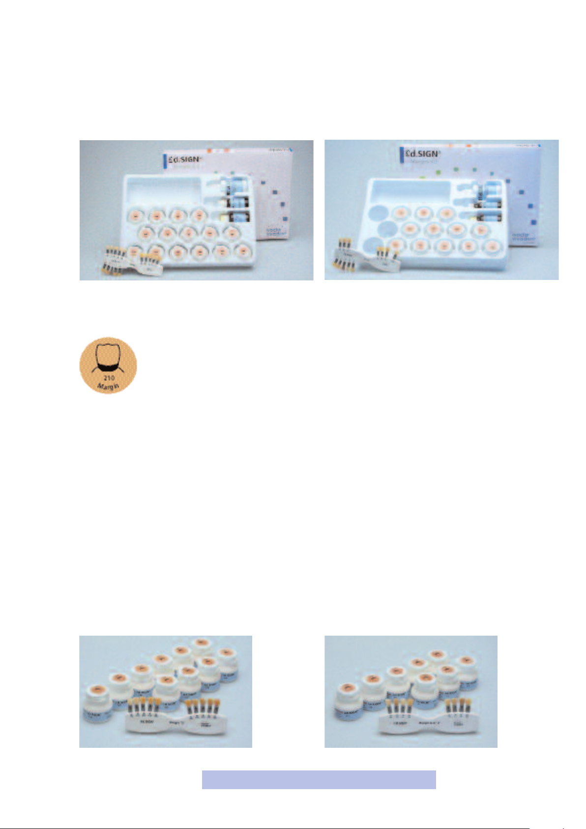
IPS d.SIGN Margin Kits
d.SIGN Margin Kit Chromascop
IPS
IPS d.SIGN Margin
The IPS d.SIGN Margin material permits the
design of a ceramic shoulder. They are
available in Chromascop and A–D shades.
Additionally, there are 4 Intensive Margin
materials to achieve special effects. The
Delivery form
Chromascop
IPS d.SIGN Margin Kit
– 10 IPS d.SIGN Margin materials, 20 g each
Shades: 130, 140, 210, 220, 230, 310, 410, 420, 430, 510
– 4 IPS d.SIGN Intensive Margin material, 20 g each
Shades: yellow
1 IPS d.SIGN Margin Add-On material, 20 g
–
– 1 IPS d.SIGN Margin Build-Up liquid, 60 ml
– 1 IPS d.SIGN Margin Separating liquid, 20 ml
1 IPS d.SIGN Ceramic separating liquid with brush, 15 ml
–
– 1 IPS d.SIGN Margin material shade guide
, orange, orange-pink, opaque
d.SIGN Margin Kit A–D
IPS
Margin Add-On material is used for
subsequent adjustments of the shoulder
area and the corresponding accuracy of fit (see
'Materials Combination Table' on
page 62 ff).
A–D
IPS d.SIGN Margin Kit
– 7 IPS d.SIGN Margin materials, 20 g each
Shades: A2, A3, A3.5, B2, B3, C3, D2/D3
– 4 IPS d.SIGN Intensive Margin materials, 20 g each
Shades: yellow, orange, orange-pink, opaque
– 1 IPS d.SIGN Margin Add-On material, 20 g
– 1 IPS d.SIGN Margin Build-Up liquid, 60 ml
1 IPS d.SIGN Margin Separating liquid, 20 ml
–
– 1 IPS d.SIGN Ceramic separating liquid with brush, 15 ml
1 IPS d.SIGN Margin material shade guide
–
Refill
IPS d.SIGN Margin material, 20 g each
–
Shades: 110, 120, 130, 140, 210, 220, 230, 210, 320,
330, 340, 410, 420, 430, 440, 510, 520, 530, 540
– IPS d.SIGN Margin '2' material shade guide
The various pr
oduct r
Refill
– IPS d.SIGN Margin material, 20 g each
Shades: A1, A2, A3, A3.5, A4, B1, B2, B3, B4, C1, C2, C3,
C4, D2/D3, D4
– IPS d.SIGN Margin '2' material shade guide A-D
ange may vary fr
12
om country to country
.
Page 13
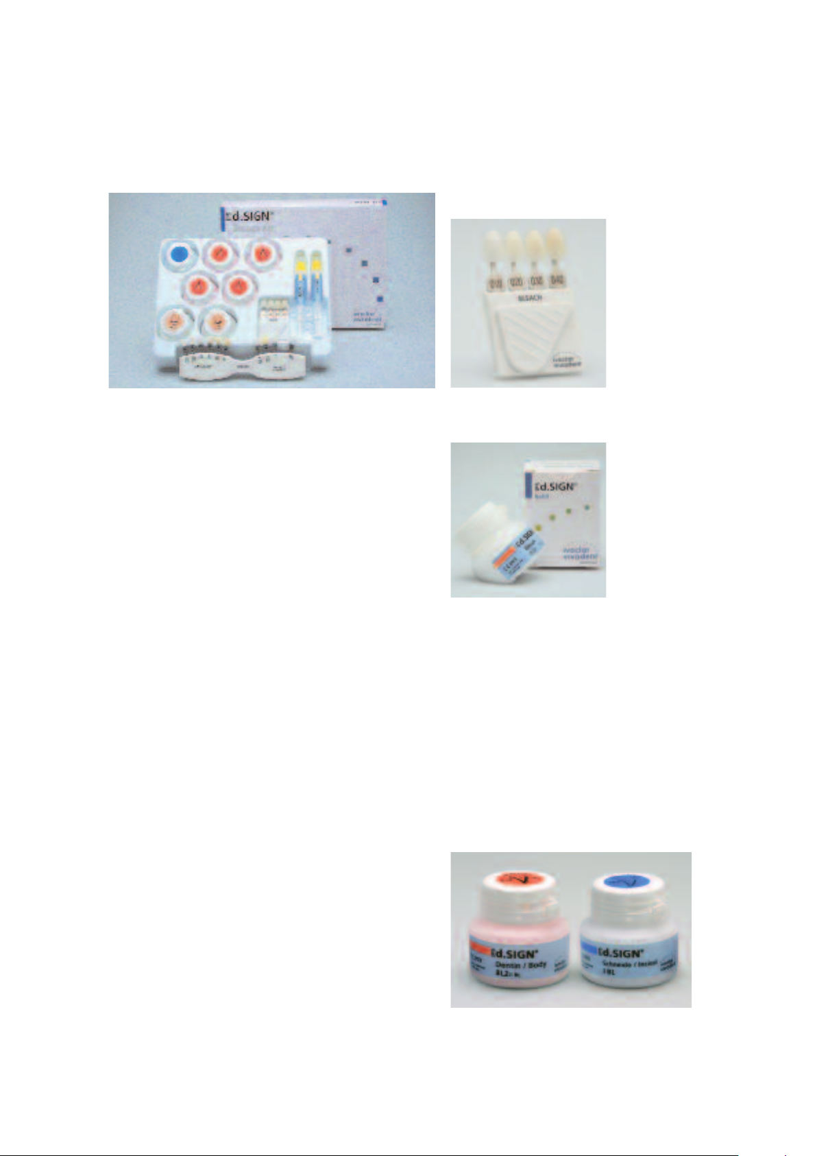
IPS d.SIGN Bleach Kit
Delivery form
IPS d.SIGN Bleach
he ultra-light shades enable
T
ptimum integration of the
o
restoration in a bleached
environment (see 'Materials
Combination Table' on
page 62 ff).
IPS d.SIGN Bleach Kit
2 IPS d.SIGN Opaquers, 3 g each
–
Shades: 010/020, 030/040
– 2 IPS d.SIGN Margin materials, 20 g each
Shades: 010/020, 030/040
– 4 IPS d.SIGN Dentin materials, 20 g each
Shades: 010, 020, 030, 040
– 1 IPS d.SIGN Transparent-Incisal material, 20 g, T-S1
– IPS d.SIGN Bleach material shade guide
IPS d.SIGN Bleach Kit BL
Four accurately coor
demands related to contemporary “white aesthetics” (see
page 67 Combination table).
dinated shades meet the highest
Delivery form
IPS d.SIGN Bleach Kit BL
–
2 IPS d.SIGN Opaquer 3 g each; Shades: BL1/BL2, BL3/BL4
– 4 IPS d.SIGN Dentin 20 g each; Shades: BL1, BL2, BL3, BL4
– IPS d.SIGN Incisal, 20 g; Shade: BL
IPS d.SIGN Margin 20 g each; Shade: BL1, BL4*
–
IPS d.SIGN Deep Dentin 20 g each; Shades: BL1, BL4*
–
– IPS d.SIGN Add-On, 20 g; Shade: BL
IPS d.SIGN/IPS InLine material shade guide BL
–
– Shade guide Bleach BL
IPS d.SIGN Bleach Refill
– IPS d.SIGN Deep Dentin
material, 20 g
Shade 010
Refill
– All products are also available as Refill
* The Margin and Deep Dentin materials are only available in
shades BL1 and BL4. Shades BL2 and BL3 can be achieved
by mixing the materials as following:
BL2: 2/3 BL1 : 1/3 BL4
BL3: 1/3 BL1 : 2/3 BL4
13
Page 14
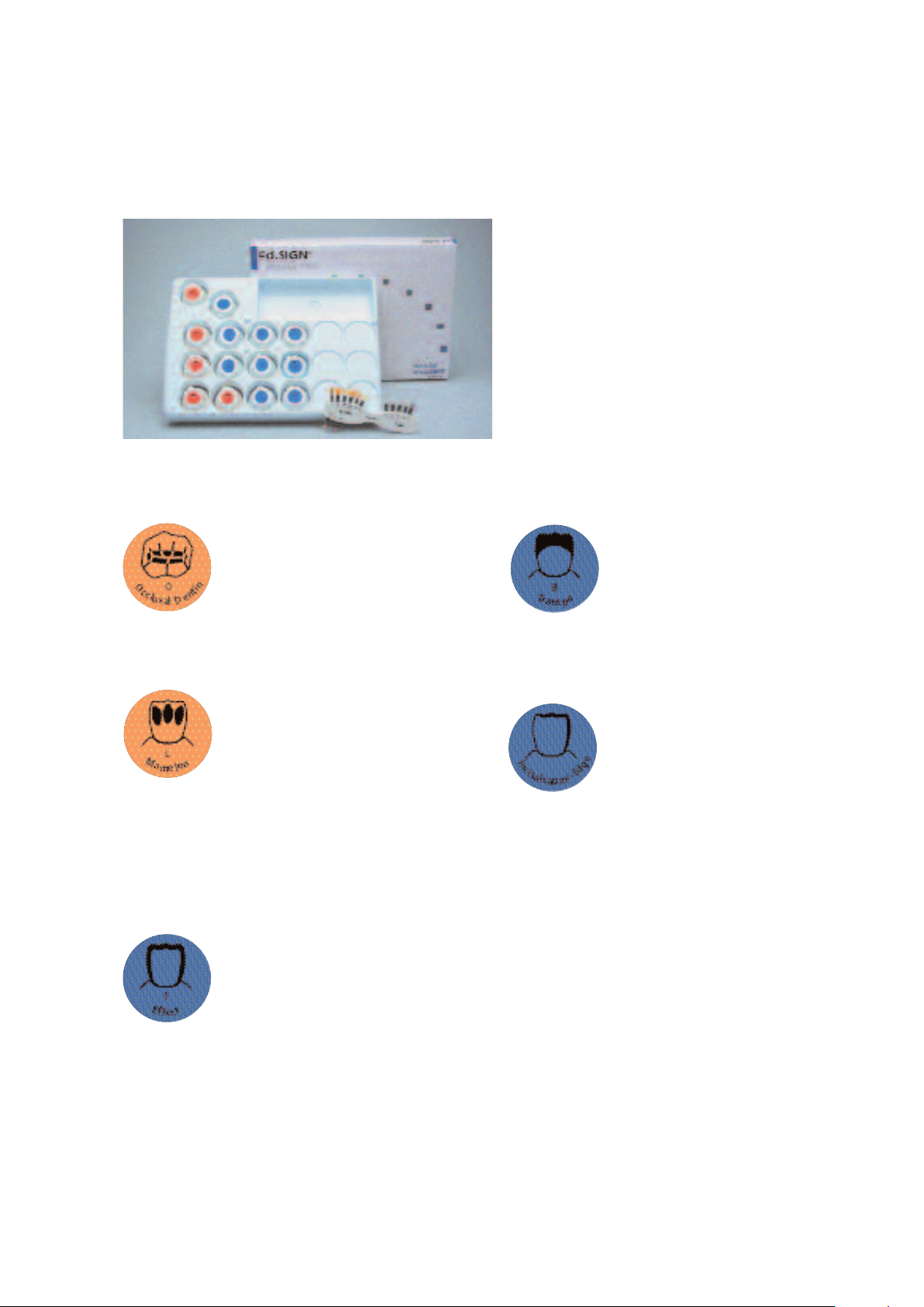
IPS d.SIGN Impulse 1 Kit
5 ready-mixed individual fluorapatite leucite ceramic
1
materials ranging from Mamelon to Opal materials facilitate
the application of true-to-nature effects.
IPS d.SIGN Occlusal Dentin
The Occlusal Dentin materials are available in
two different shades. They are used to
provide the basic shade for occlusal surfaces
and to intensify the chroma (see 'Materials
Combination Table' on page 66).
IPS d.SIGN Mamelon
The Mamelon materials are available in three
different shade gradations. They demonstrate
high opacity and optimum masking
capabilities even when applied in very thin
layers. Depending on the working habits of
the user, the material is applied in thin stripes
on reduced dentin. In this way, an
individualized appearance of the incisal third
can be achieved (see 'Materials Combination
Table' on page 66).
IPS d.SIGN Ef
fect
Users may chose between six shade
gradations of the IPS d.SIGN Ef
Starting with Effect 1, which demonstrates
true-to-nature opalescence in conjunction
with high translucency, the value gradually
increases from Effect 2 to Effect 5. In
contrast, the violet material reduces the
value in the incisal area (see 'Material
Combination Table' on page 66).
fect materials.
IPS d.SIGN Transparent
The Transparent materials are available in
three shade nuances. They are suitable to
reproduce shaded, transparent areas,
particularly in the incisal third (see 'Materials
Combination Table' on page 66).
IPS d.SIGN Incisal Edge
This material is used to achieve what is
known as the 'halo effect', which is caused
in natural teeth by light refraction at the
incisal edge (see 'Materials Combination
able' on page 66).
T
Delivery form
IPS d.SIGN Impulse 1 Kit
2 IPS d.SIGN Occlusal Dentin materials, 20 g each
–
Shades: orange, brown
– 3 IPS d.SIGN Mamelon materials, 20 g each
Shades: light, yellow-orange, salmon
– 6 IPS d.SIGN Effect materials, 20 g each
Gradation: Ef
violet
– 3 IPS d.SIGN Transparent materials, 20 g each
Shades: blue, brown-grey, orange-grey
1 IPS d.SIGN Incisal Edge material, 20 g
–
– 1 IPS d.SIGN Impulse 1 material shade guide
fect 1, Ef
fect 2, Ef
fect 3, Effect 4, Effect, 5,
14
Page 15
IPS d.SIGN Impulse 2 Kit
14 ready-mixed Impulse materials based on the inspiration
and philosophies of renowned experts, such as Enrico Steger,
onald F. Cornell, and Dr. Robert R. Winter.
D
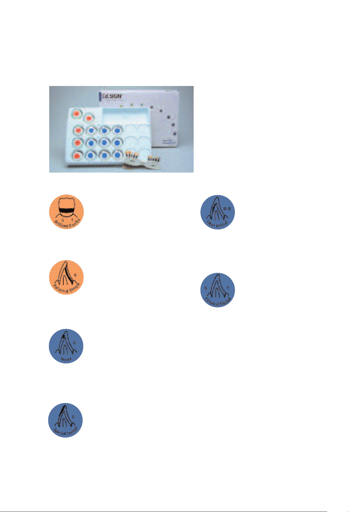
IPS d.SIGN Brilliant Dentin
In order to highlight the shade of certain
areas of the tooth, IPS d.SIGN Brilliant
Dentin is applied on the opaquer in very thin
layers. These special dentin materials
demonstrate outstanding opacity and colour
saturation (see 'Material Combination Table'
on page 66).
IPS d.SIGN Palatinal Dentin
These dentin materials have been especially
developed for use in palatal areas where
space is limited. They only need to be
covered with Incisal materials and provide
the required colour saturation for the palatal
fossa (see 'Materials Combination Table' on
page 66).
IPS d.SIGN Insert
IPS d.SIGN Insert materials are mainly used in
incisal ar
incisal and dentin materials for shade
characterization purposes. With Insert grey, a
true-to-nature in-depth effect can be
achieved (see 'Materials Combination Table'
on page 66).
IPS d.SIGN Special Incisal
These two special incisal materials may either
be mixed with IPS d.SIGN Incisal materials to
modify and intensify the shade or applied
directly (see 'Materials Combination Table' on
page 66).
eas and are applied between the
IPS d.SIGN Inter Incisal
This special incisal material is used when high
brightness values in the incisal area are
needed or to increase the brightness value in
the incisal third when space is limited. It can
be applied alone or mixed with other
materials (see 'Materials Combination Table'
on page 66).
IPS d.SIGN Cervical Incisal
These very transparent cervical incisal
materials are used to achieve true-to-nature
effect of depth in the cervical third. In
contrast to conventional Transparent
materials, these special materials
demonstrate a strong white fluorescence (see
'Materials Combination Table' on page 66).
Delivery form
IPS d.SIGN Impulse 2 Kit
– 3 IPS d.SIGN Brilliant Dentin materials, 20 g each
Shades: yellow, orange, white
2 IPS d.SIGN Palatinal Dentin material, 20 g each
–
Shades: yellow, red
2 IPS d.SIGN Insert materials, 20 g each
–
Shades: orange, grey
– 2 IPS d.SIGN Special Incisal materials, 20 g each
Shades: yellow, grey
1 IPS d.SIGN Inter Incisal material, 20 g
–
Shade: white-blue
– 4 IPS d.SIGN Cervical Incisal materials, 20 g each
Shades: yellow
– IPS d.SIGN Impulse 2 material shade guide
, orange-pink, khaki, orange
15
Page 16
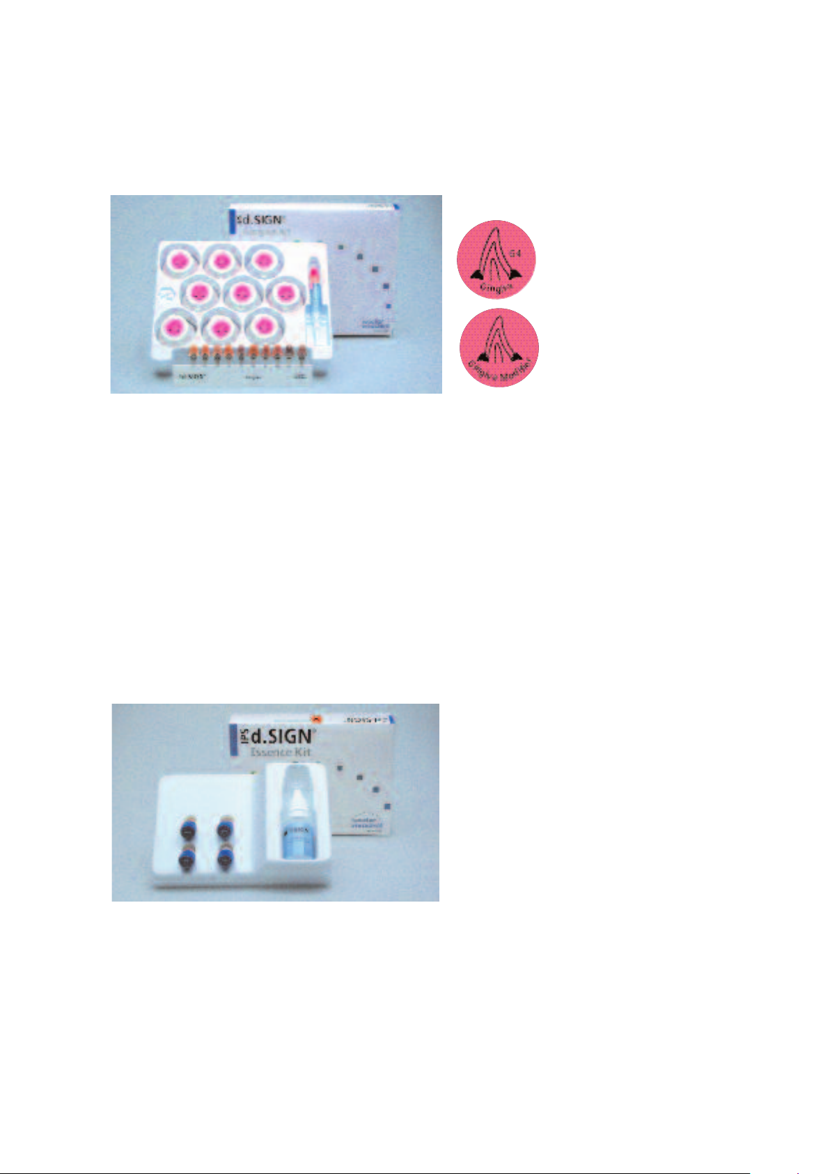
IPS d.SIGN Gingiva Kit
Delivery form
IPS d.SIGN Gingiva Kit
– 1 IPS d.SIGN Gingiva Opaquer, 3 g
– 5 IPS d.SIGN Gingiva materials, 20 g each
Gradations: G1, G2, G3, G4, G5
– 4 IPS d.SIGN Gingiva Modifiers, 20 g each
Gradations: GM1, GM2, GM3, GM4
– IPS d.SIGN Gingiva material shade guide
IPS d.SIGN Gingiva and Gingiva Modifier
These special Gingiva materials are used in
combination with the Gingiva Modifiers
epending on the individual situation of the
d
atient. The shade gradations range from
p
orange to reddish to bluish (see 'Materials
Combination Table' on page 67).
IPS d.SIGN Essence Kit
Delivery form
IPS d.SIGN Essence Kit
– 1 IPS d.SIGN Essence, 1 g, orange
– 1 IPS d.SIGN Essence, 1 g, yellow
– 1 IPS d.SIGN Essence, 1 g, grey
– 1 IPS d.SIGN Essence, 1 g, brown
– 1 IPS d.SIGN Glazing and Staining liquid, 15 ml
IPS d.SIGN Essence materials are ceramic stains in powder
form that may be mixed with IPS d.SIGN layering materials in
der to intensify the shade. Furthermore, IPS d.SIGN Essence
or
can be used for surface characterizations to repr
special characteristics of the natural tooth (see 'Materials
Combination Table' on page 67)
oduce the
16
Page 17

IPS d.SIGN Stains Kit
Delivery form
IPS d.SIGN Stains Kit
– 1 IPS d.SIGN Stains, 1 g, white
– 1 IPS d.SIGN Stains, 1 g, mahogany
– 1 IPS d.SIGN Stains, 1 g, khaki
– 1 IPS d.SIGN Stains, 1 g, orange
– 1 IPS d.SIGN Stains, 1 g, grey
– 1 IPS d.SIGN Stains, 1 g, vanilla
– 1 IPS d.SIGN Stains, 1 g, crackliner
– 1 IPS d.SIGN Stains, 1 g, olive
IPS d.SIGN Stains
– 1 IPS d.SIGN Stains, 1 g, yellow
1 IPS d.SIGN Stains, 1 g, black
–
– 1 IPS d.SIGN Stains, 1 g, maroon
– 1 IPS d.SIGN Stains, 1 g, basic blue
– 1 IPS d.SIGN Stains, 1 g, basic red
– 1 IPS d.SIGN Stains, 1 g, basic yellow
– 1 IPS d.SIGN Glaze, 3 g
– 1 IPS d.SIGN Glaze and Stain liquid, 15 ml
hese intensive stains in
T
aste form are available in
p
14 different shades. They are
used to reproduce natural
characteristics on the
eramic surface. With the
c
three primary colours basic
blue, basic red, and basic
yellow, custom shades may
be developed (see 'Materials
Combination Table' on
page 67).
IPS d.SIGN Shade Kit
Delivery form
IPS d.SIGN
– 1 IPS d.SIGN Shade 1, 3 g
– 1 IPS d.SIGN Shade 2, 3 g
– 1 IPS d.SIGN Shade 3, 3 g
1 IPS d.SIGN Shade 4, 3 g
–
Combination table
IPS d.SIGN Shade
Shade Kit
IPS d.SIGN Shade
These 7 dentin stains in
paste form make shade
adjustments to IPS d.SIGN
restorations possible. They
are coordinated with the
20 Chromascop shades and
the 16 A–D shades (see
'Materials Combination
able' on page 67).
T
– 1 IPS d.SIGN Shade 5, 3 g
– 1 IPS d.SIGN Shade 6, 3 g
– 1 IPS d.SIGN Shade 7, 3 g
1
2
3
4
5
6
7
Chromascop
A–D Shades
110, 120,
130
A1, B1, B2
140, 210,
220, 230,
240
A2, A3,
A3,5
310, 320,
330
B3, B4, D4
17
340, 540,
A4
410, 420
C1, D2, D3
430, 440,
510
C2, C3, C4
520, 530
Page 18
d.SIGN – Liquids
IPS
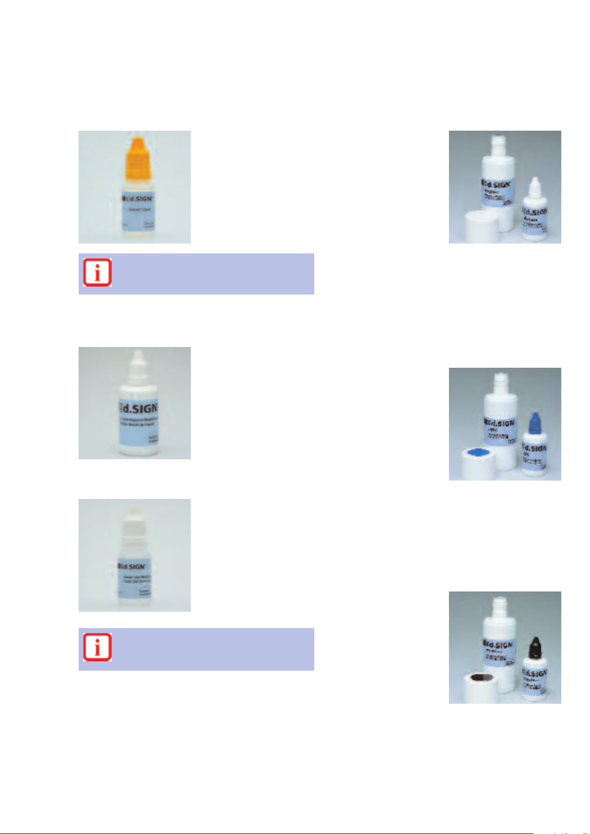
IPS d.SIGN Opaquer Liquid, 15 ml
his liquid is used to adjust
T
the consistency of IPS d.SIGN
Paste Opaquer materials. Do
not excessively dilute the
paste opaquer with the
paquer liquid.
o
Components: Polymer,
butylene glycol, and
glycerine
The Opaquer Liquid must not be used to mix
opaquers, as it is the case in power/liquid opaquer
systems.
IPS d.SIGN Margin Build-Up Liquid, 60 ml
Use to mix the IPS d.SIGN
Margin materials.
Components: Water,
cellulose derivative
IPS d.SIGN Glaze and Stain Liquid, 15 ml
This liquid is used to adjust
the consistency of IPS d.SIGN
Stains, IPS d.SIGN Shade,
IPS d.SIGN Essence, and
IPS d.SIGN Glaze.
Components: Butylene
glycol
Warning
Butylene glycol is irritating. Avoid contact. Do not
inhale vapours.
IPS d.SIGN Build-Up Liquid Medium, 60 and 250 ml
This liquid is suitable for
ixing IPS d.SIGN materials
m
or most layering techniques
f
and restorations. The BuildUp Liquid Medium is particularly suitable for technicians
ho prefer a longer working
w
time and enhanced stability
of IPS d.SIGN. In this way,
IPS d.SIGN may be processed
in smaller increments, with-
ut the constant need of
o
moistening. Given the longer
working time than with the
Build-Up Light, a longer
closing time (pre-drying time)
IPS d.SIGN Build-Up Liquid Light, 60 and 250 ml
This liquid is suitable for
mixing IPS d.SIGN materials
that will be used for smaller
restorations or when smaller
amounts of material are
needed for 2nd dentin and
incisal firings (corrective
firing). The Build-Up Liquid
Light is suitable for those
who prefer a drier working
consistency, thus avoiding
the need for constant
blotting since the liquid
evaporates much quicker
this way, IPS d.SIGN can be
IPS d.SIGN Build-Up Liquid Premium, 60 and 250 ml
This liquid is suitable for
mixing IPS d.SIGN materials
that will be used for
fabricating larger restorations
where a longer working time
and smooth consistency is
desired. The Build-Up Liquid
Premium is suitable for
technicians who prefer a
long working time and moist
material coupled with high
stability. In this way,
IPS d.SIGN can be pr
without the need for
constant moistening. Since
the material stays moist for a
longer period of time
controlled blotting is
18
. In
ocessed
is required for the firing
ocedure.
pr
Components: Water,
butylene glycol, and
additives
easily manipulated with an
instrument.
Components: Water,
butylene glycol, and
additives
equired as well as a longer
r
closing time (pre-drying
time) for the firing
procedure.
Components: Water,
butylene glycol-chloride
solution
Page 19
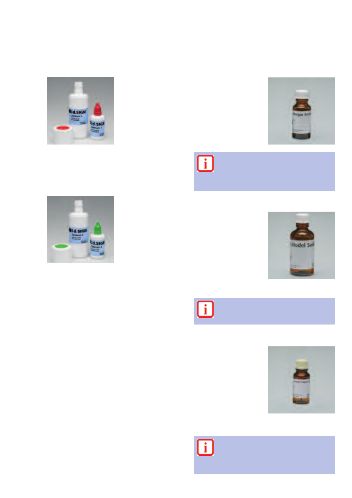
PS d.SIGN Build-Up Liquid Optimum 1,60 and 250 ml
I
xcellently suitable for
E
mixing IPS d.SIGN, with its
outstanding firing behaviour
and lowest possible
hrinkage. The materials are
s
easily suctioned off and
condensed and are
particularly suitable for the
manual reduction of
aterials with the help of
m
instruments.
IPS Margin Sealer, 20 ml
his separating liquid is used
T
to seal the gypsum die when
fabricating a ceramic
shoulder with IPS d.SIGN
Margin materials.
Components: Wax dissolved
in hexane
Components: Water, polyethylene glycol (PEG), and
additives
IPS d.SIGN Build-Up Liquid Optimum 2, 60 and 250 ml
Excellently suitable for
mixing IPS d.SIGN, with its
properties that support the
build-up, as well as the
optimized firing properties
with low shrinkage. This
liquid is particularly suitable
for targeted material
application without
continuous suction.
Components: Water, polyethylene glycol (PEG), and
additives
Warning:
Hexane is highly flammable and detrimental to
health. Avoid contact of the material with skin and
eyes. Do not inhale the vapours. Keep the material
away from open fire.
IPS Model Sealer, 50 ml
This separator is used to seal
the pontic tissue areas and
interproximal contact area
when working with
IPS d.SIGN layering materials.
The IPS Model Sealer closes
the pores of the gypsum and
prevents the moisture in the
ceramic material from being
absorbed by the gypsum.
Components: Ethyl acetate,
nitro-cellulose, softener
Warning
Ethyl acetate is highly flammable
away from open fire. Do not inhale the vapours.
. Keep material
IPS Ceramic Separating Liquid, 15 ml
This Separating Liquid is
used on areas that have
been sealed with either the
IPS Margin Sealer Liquid or
the IPS
Model Sealer
. Use of
this liquid will ensure a clean
separation between the
ceramic material and the
gypsum model and/or die.
Components: Paraffin oil
Other build-up liquids or separating liquids must
not be used.
They may contain or
that do not burnout at the firing temperatures
used for IPS d.SIGN and leave a residue that will
cause discolor
19
ation in the cer
ganic additives
amic.
Page 20
d.SIGN – Shade selection
IPS
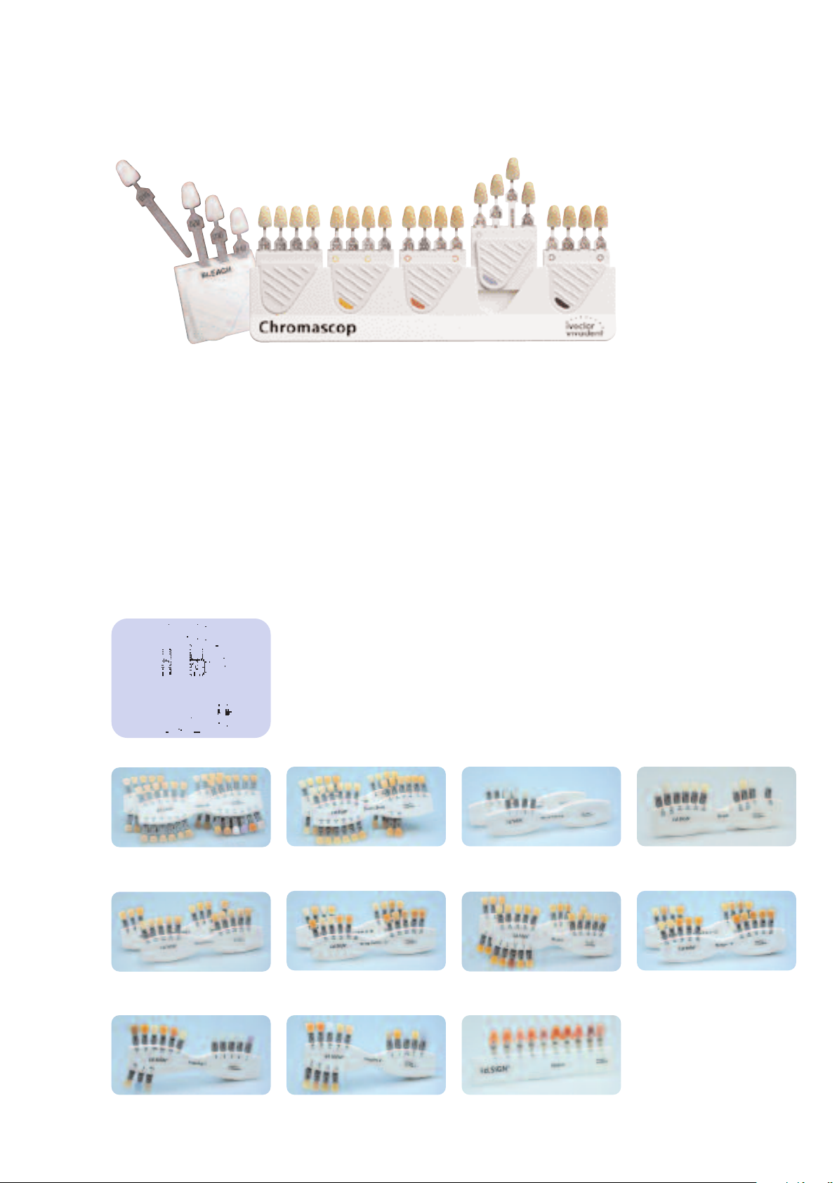
The Chromascop shade guide represents the shade standard for Ivoclar Vivadent products.
With the logical arrangement of the individual shades, the Chromascop permits exact and
ficient shade determination. The 20 shades are divided into five detachable shade groups.
ef
IPS d.SIGN material shade guides
The shade guides fired from original materials are also an integrated part of the IPS d.SIGN
product system. For reasons of light refraction, the new shade tabs have been given an
anatomical shape and a certain surface structure. On the reverse side, the teeth are smooth,
i.e. without any texture whatsoever, which facilitates shade comparison with the prepared die
and shaded cementation media. The smooth side of shade tabs may be individually ground
to determine the layering. The shade tabs are fired from original materials under laboratorytype conditions. In this way, they correspond with the desired result.
IPS d.SIGN Opaquer material shade guide
Chromascop and A–D
IPS d.SIGN Deep Dentin material shade guide
Chromascop and
A–D
IPS d.SIGN Dentin material shade guide
Chromascop and A–D
IPS d.SIGN Deep Dentin '2' material shade guide
Chromascop and Deep Dentin
A–D '2'
IPS d.SIGN Incisal/Transparent material shade guide
Chromascop and
IPS d.SIGN Margin material shade guide
Chromascop and A–D
A–
IPS d.SIGN Bleach material shade guide
IPS d.SIGN Margin '2' material shade guide
Chromascop and Margin
A–D '2'
IPS d.SIGN Impulse 1 material shade guide
Chromascop and A–D
IPS d.SIGN Impulse 2 material shade guide
Chromascop and
A–D
IPS d.SIGN Gingiv
Chromascop and
20
a material shade guide
A–D
Page 21
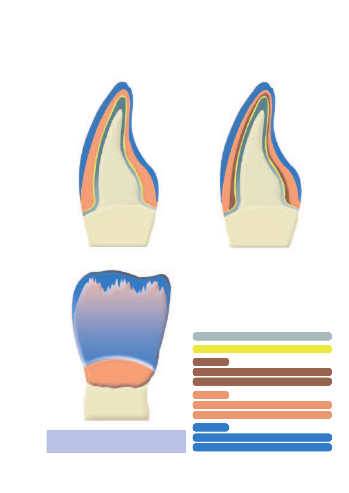
d.SIGN – Layering diagram
IPS
Chromascop – ideal space
Chromascop – limited space
the incisal material extends up to
In Chromascop layering
the cervical third. The indications on the right are reference
values.
,
Framework
Opaquer
Deep Dentin
cervical
incisal
Dentin
cervical
incisal
Incisal
cervical
incisal
21
ideal
space
0.3 mm
0.1 mm
–
–
1.0 mm
0.7 mm
0.2 mm
0.5 mm
limited
space
0.3 mm
0.1 mm
0.3 mm
0.1 mm
0.5 mm
0.3 mm
0.1 mm
0.4 mm
Page 22

A–D – ideal space
A–D – limited space
the incisal material extends to the center of
In A–D layering
the cervical third. The indications on the right are reference
values.
,
Framework
Opaquer
Deep Dentin
cervical
incisal
Dentin
cervical
incisal
Incisal
cervical
incisal
22
ideal
space
0.3 mm
0.1 mm
–
–
0.9 mm
0.7 mm
0.2 mm
0.5 mm
limited
space
0.3 mm
0.1 mm
0.3 mm
0.1 mm
0.5 mm
0.3 mm
0.1 mm
0.4 mm
Page 23

d.SIGN – Framework design
IPS
crowns
4
/
3
l
l
l
l
l
l
l
l
l
l
l
l
l
l
l
l
l
l
l
l
l
l
l
l
l
l
l
–
–
–
–
Telescope and
conus crowns
Root canal
posts
l
l
l
l
–
l
l
l
l
l
l
l
l
l
l
l
l
l
l
l
l
l
l
l
l
l
l
l
l
l
l
l
l
l
l
–
l
–
l
–
l
l
l
l
l
l
l
l
l
l
l
l
l
l
l
l
l
l
l
l
l
l
Ceramic crowns
l
l
l
l
l
l
l
l
l
l
l
l
l
l
l
l
l
l
l
l
l
l
l
l
l
l
l
l
l
l
l
Long span
l
l
l
l
l
l
l
l
l
l
l
l
l
l
l
l
l
l
l
l
l
l
l
l
l
l
l
l
l
l
Alloy
Implant Series
Callisto Implant 78
IS-85
IS-64
allisto Implant 60
C
High gold content
Brite Gold
Brite Gold XH
Golden Ceramic
Aquarius Hard
Aquarius
IPS d.SIGN 98
Y
Aquarius XH
Y-Lite
Sagittarius
IPS d.SIGN 96
Reduced gold content
IPS d.SIGN 91
W
W-5
Lodestar
W-3
Evolution Lite
Palladium based
Capricorn 15
IPS d.SIGN 84
d.SIGN 67
IPS
Spartan Plus
IPS d.SIGN 59
d.SIGN 53
IPS
Ni based
Pisces Plus
4all
IPS d.SIGN 15
Co based
IPS d.SIGN 30
Inlays
–
–
–
–
l
l
–
l
l
l
–
–
–
–
l
–
–
–
–
–
–
–
–
–
–
–
–
–
–
–
–
Onlays
l
l
l
l
l
l
l
l
l
l
l
l
l
l
l
l
l
l
l
l
l
l
l
l
l
l
l
–
–
–
–
bridges
Short span
bridges
l
l
l
l
–
–
l
–
l
–
l
l
l
l
l
l
l
l
l
l
l
–
l
l
l
l
l
l
l
l
l
l
Implant
l
l
l
l
–
–
–
–
–
l
–
l
–
l
–
l
–
l
l
l
–
l
l
l
l
l
l
–
–
–
l
Partial dentures
Superstructures
l
l
l
l
–
–
–
l
–
l
–
l
l
l
–
l
l
l
l
l
–
l
l
l
l
l
l
l
–
–
l
oduct lines may vary fr
The pr
om country to country.
When designing frameworks to be veneered with ceramic materials, the following
parameters have to be observed:
1. Functional support of the veneering ceramic
2. Framework design for porcelain shoulders
3. Framework stability
4. Framework design for bridges
5. Design of bridge pontics
6. Interface between metal and ceramic
23
Page 24

1. Functional support of the veneering ceramic
tress peaks, which may cause delamination or cracks. Sharp
The framework should reflects the shape of the tooth in a
reduced form. The framework should be designed in such a
way that it supports the cusps so that an even layer of the
eneering ceramic can be used in the cusp/fissure area. In
v
this way, the masticatory forces are exerted on the framework rather than on the veneering ceramic. Furthermore,
the framework should not have any sharp angles or edges
see diagram), so that the masticatory forces do not cause
(
Anterior crowns
correct wrong
s
angles or edges should be rounded in the wax-up so that
the minimum framework thickness is not compromised. The
wall thickness of the metal framework for single crowns
after finishing should be at least 0.3 mm and 0.5 mm for
ridge abutments (see diagram). For further information,
b
please refer to the Instructions for Use of the alloy being
used.
Premolar crowns
Molar cr
owns
correct wrong
correct wrong
24
Page 25

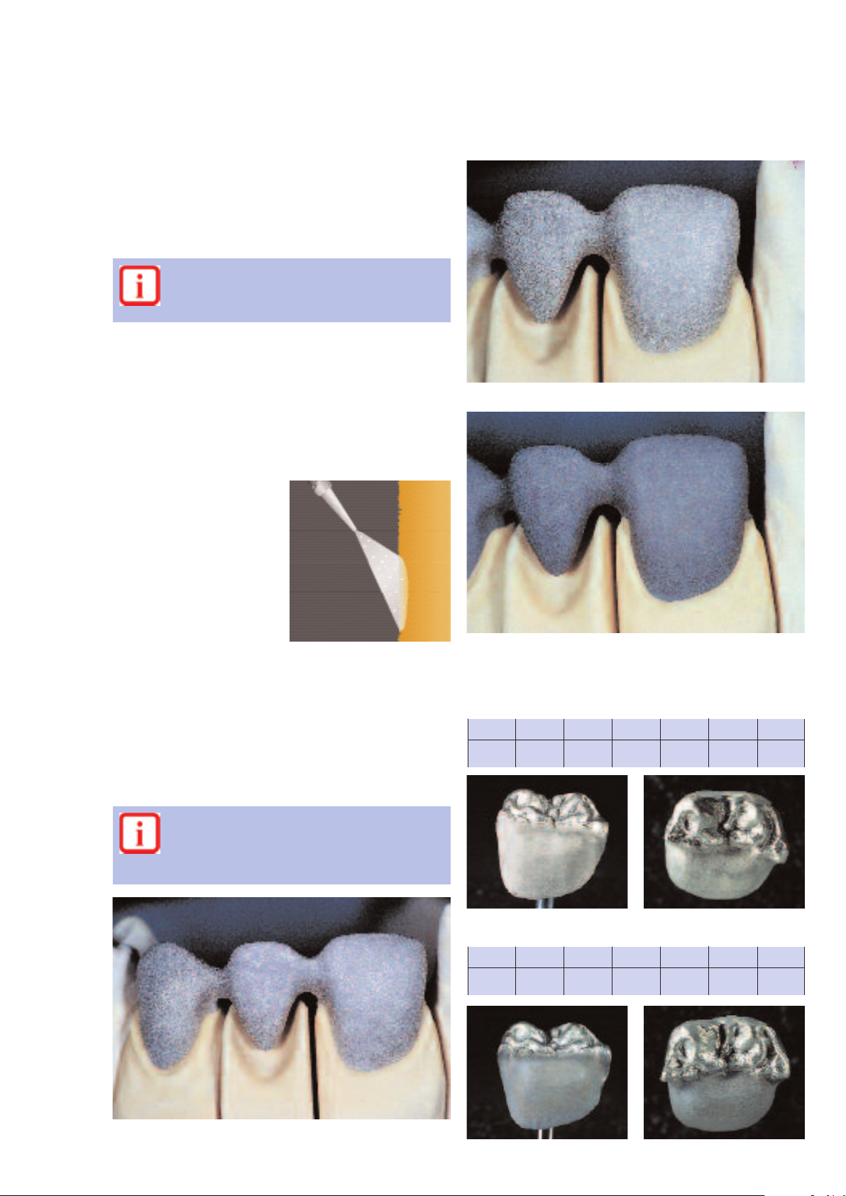
2. Framework design for porcelain shoulders
When fabricating porcelain shoulders, make sure that the
ramework is supported by the prepared tooth rather than
f
he veneer. To achieve this the framework is reduced exactly
t
to the inner edge of the chamfer or shoulder preparation. In
this way, functional support of the framework by the
prepared tooth is achieved. A framework that accuractly fits
he prepared tooth is essential in order to keep the ceramic
t
material from getting on the inner surface of the framework.
correct
3. Framework stability
The dimensions of the interproximal connector greatly
influences the stability of the restoration during the
laboratory procedure as well as the clinical long-term success
after cementation. Therefore, the dimension of the
connector area must be adequate for the alloy being used.
This is especially important if a bio-alloy or high-gold alloy is
to be used.
wrong
Double the width of the
connector
= double the stability
Single connector width
= single stability
Double the height of the
connector at single width
= eightfold the stability
25
Page 26

4. Framework design for bridges
Frameworks veneered with ceramic materials are subject to
thermal stress during the firing procedures and to
masticatory stress after cementation. Therefore, the
orresponding forces must be transferred to the framework
c
rather than the veneer. In particular, adequate framework
thickness must be ensured in the connector area between
the abutment and the pontic in bridge reconstructions.
he design of the framework must meet the visual,
T
unctional and periodontal hygiene requirements of the
f
patient. A functional wax-up reduced to allow space for
the ceramic material is the optimum prerequisite. During the
laboratory procedures the framework is repeatedly exposed
to high temperatures. These firing temperatures may cause
the framework to distort and compromise the accuracy of fit
if it has not been properly designed and the required
hickness observed. A scallop-type design with interproximal
t
reinforcement will provide the necessary strength needed to
avoid deformation of the framework. Also, this type of
proper framework design (e.g. with cooling grooves) will
ensure even cooling of the restoration once it is removed
rom the porcelain furnace after firing. This is particularly
f
important if bio-alloys or high-gold alloys are used. The
corresponding failures can be prevented as described under
point 1.
n order to ensure proper oral hygiene with bridges, the
I
design of the interdental areas should be given special
attention. Adequate opening of the interdental area should
be considered when designing the framework without
creating black triangles. In this way, periodontal hygiene may
be performed using interdental brushes and dental floss.
correct
ect
corr
wrong
26
Page 27

5. Design of bridge pontics
Bridge pontics are designed taking aesthetic and functional
aspects into account, as well as oral hygiene. The area of the
pontic that contacts the alveolar ridge should be made of
eramic. In order to ensure adequate stability between
c
Bridge pontic design – ovate pontics Bridge pontic design – saddle-type pontics
bridge pontic and the bridge abutments, a palatal and/or
ingual scallop is recommended. Furthermore, to ensure even
l
cooling of the bridge pontic that absorbs the most heat,
additional cooling grooves are advantageous.
6. Interface between metal and ceramic
The interface between the metal framework and the venee
ring ceramic must be clearly defined and, if possible,
incorporate a right angle finish line. The juncture between
the metal framework and the veneering ceramic must not
be located in the contact area nor on surfaces involved in
masticatory functions. Furthermor
interface in the marginal area does not come into contact
e, make sure that the
with the gingiva, particularly if a tapered crown margin is
designed (e.g. no metal margin and no ceramic shoulder).
In this way, irritation of the gingiva can be prevented. The
interface in the interdental area should be designed in such
a way that cleaning of these difficult-to-access areas is
possible.
27
Page 28

d.SIGN – Instructions for Use
IPS
Starting situation
Fabricate a master model or a model with detachable
segments on the basis of the impression in the usual manner.
t is advisable to apply a sealer to harden the surface to
I
protect the die from abrasion. The application of a sealer
must not cause any changes in the dimension of the die.
After that, a spacer may be applied in the usual manner.
A model with detachable segments is used as the basis.
Fabricating the framework
When fabricating the framework, make sure that the
minimum wall thickness
rowns and 0.5 mm for bridge abutments. These dimensions
c
are the prerequisite for the stability of the metal framework
and the durable bond between the metal and ceramic
material. If the stipulated framework and connector
dimensions are not observed, stress within the material may
ause delamination of the ceramic material and distortion of
c
the framework.
Recommended procedure
. Complete modelling of the anatomical tooth shape
1
2. Reduce to make room for the veneering materials
3. Waxing of the contact points and connector areas
4. Checking the occlusal and proximal contact points
after finishing is 0.3 mm for single
Dies isolated with a sealer, followed by a spacer layer.
28
Page 29

Contouring
he framework reflects the reduced anatomical tooth shape
T
see 'Functional support of the veneering ceramic' on page
(
24). In this way, the ceramic material may be applied in even
layers and is adequately supported. For that purpose, the
properties of the different alloys (e.g. firing stability) must be
aken into consideration.
t
– Undersized metal frameworks result in increased
hrinkage of the veneering ceramic and require
s
additional corrective firings.
– If the metal framework is too small, the veneering
ceramic is not adequately supported, which may lead to
cracks and delamination, particularly in very thick ceramic
layers.
Finishing the metal framework
he cast metal framework is finished using tungsten carbide
T
etal burs or ceramic-bonded grinding instruments. The
m
marginal area of the framework is reduced up to the inner
edge of the chamfer or shoulder preparation (labial or
circular) to make room for the ceramic shoulder.
– Use reduced pressure when working with softer
alloys.
– Work in one direction only to avoid overlapping and
inclusions in the metal surface.
– Do not use diamond grinding instruments. Diamond
particles may be trapped in the alloy and cause bubbles
in the cer
amic material during firing.
The frameworks are contoured according to the static requirements…
... and the properties of the alloy used.
ameworks are finished using tungsten carbide metal burs…
Cast metal fr
... or ceramic-bonded grinding instruments.
29
Page 30
Oxide firing
After grinding, carefully blast the framework with type
80–100 aluminium oxide (Al
edium). When using IPS d.SIGN alloys, the required
m
pressure is 1.5–2.0 bar.
Use only disposable, pure Al2O3to blast the alloy
surface. Observe the Instructions for Use of the
corresponding alloy manufacturer.
Blasting improves the mechanical bond. It results in the
object surface being roughened and considerably enlarged.
In order to prevent inclusions of blasting medium residue in
the ceramic, we recommend blasting the alloys with the
indicated pressure while keeping the nozzle at a flat angle to
the object surface. A contaminated metal surface may result
in the formation of bubbles during ceramic firing.
Schematic diagram of the
blasting direction
Correct angle for blasting the
alloy surface.
). (Ivoclar Vivadent special jet
2O3
... thoroughly cleaned, ...
Before the oxidation firing, clean the metal framework using
a brush under running water. Then, thoroughly clean it with
steam or in the ultrasonic cleaner. Allow the framework to
dry after cleaning. Oxidize the framework according to the
. Provide ample
instructions given by the alloy manufactur
support for the framework on the fi
er
ring tray
. This is
particularly important for long-span bridges. After oxidation,
carefully check the framework for porosity or irregular oxide
layer. Applied corr
W
ections if necessary.
hen conditioning the frameworks, the instructions
of the alloy manufacturer must be observed at all
times. Oxidation is carried out according to the
instructions of the alloy manufacturer.
.
.. and oxidized according to the instructions of the alloy manufacturer.
Correctly oxidized IPS d.SIGN alloys
Firing parameters for the oxide firing of IPS d.SIGN 98
T
925°C
1697°F
B
403°C
757°F
S
1 min.
1 min.
t
80°C
144°F
H
Ú
5 min.
5 min.
V
–
–
V
1
2
–
–
Firing parameters for the oxide firing of IPS d.SIGN 96
950
1742
T
B
C
°
°
°
403
F
757
S
C
1 min.
F
°
1 min.
80
144
t
°
H
Ú
C
5 min.
F
°
5 min.
450
842
V
V
1
C
°
°
2
°
950
F
1742
C
F
°
After grinding, the framework is carefully blasted with type 100 aluminium oxide Al
2O3
,….
30
Page 31

Firing parameters for the oxide firing of IPS d.SIGN 91
010°C
1
850°F
1
T
4
7
B
03°C
57°F
S
min.
1
min.
1
8
1
t
0°C
44°F
H
Ú
min.
5
min.
5
4
8
V
1
50°C
42°F
010°C
1
850°F
1
V
2
Firing parameters for the oxide firing of IPS d.SIGN 53
010°C
1
850°F
1
T
4
7
B
03°C
57°F
S
min.
1
min.
1
8
1
t
0°C
44°F
H
Ú
0 min.
1
0 min.
1
V
–
–
V
1
2
–
–
Firing parameters for the oxide firing of IPS d.SIGN 84
T
1010°C
1850°F
B
403°C
757°F
S
1 min.
1 min.
t
80°C
144°F
H
Ú
5 min.
5 min.
V
1
450°C
842°F
V
2
1010°C
1850°F
Firing parameters for the oxide firing of IPS d.SIGN 67
1010
1850°
T
B
C
°
°
403
F
757°
S
C
1 min.
F
1min.
80
144°
t
°
H
Ú
C
5 min.
F
5 min.
V
1
–
–
V
2
–
–
Firing parameters for the oxide firing of IPS d.SIGN 30
T
925°C
697°F
1
B
403°C
57°F
7
S
1 min.
min.
1
80°C
44°F
1
t
H
Ú
5 min.
min.
5
V
1
450°C
42°F
8
V
925°C
697°F
1
2
Firing parameters for the oxide firing of IPS d.SIGN 15
T
950°C
1742°
B
403°C
F
757°
S
1 min.
F
1 min.
t
80°C
144°
H
Ú
1 min.
F
1 min.
V
–
–
V
1
2
–
–
Firing parameters for the oxide firing of IPS d.SIGN 59
T
1010°C
1850°F
B
403°C
757°F
S
1 min.
1 min.
t
80°C
144°F
H
Ú
10 min.
10 min.
V
1
–
–
V
2
–
–
Explanation of firing parameter symbols
T = Top temperature B = Low temperature
= Dry time
S
t = heat rate of climb
Ú
V
= Vacuum start temperature V2= Vacuum off temperature
1
oduct lines may vary fr
The pr
hold time a top temperatur
=
H
om country to country
.
Some alloy types require pickling after oxide firing
and/or blasting of the oxide layer (observe instruc-
After that,
tions of the alloy manufactur
er).
thoroughly clean the framework with steam or in
the ultrasonic bath. Oxidation can be considered a
'cleaning firing' and is also used to check the
quality of the framework surface.
31
e
Page 32

1stopaquer firing (wash firing)
Extrude the desired amount of the ready-to-use opaquer
paste from the syringe and mix thoroughly. Unlike with
owder/liquid systems, the opaquer paste
p
excessively mixed with opaquer liquid. The opaquer liquid
exclusively used to adjust the consistency of the paste
is
opaquer and to rewet dried opaquer that has been used
several times. Caution: Do not excessively dilute the paste
paquer with the opaquer liquid. Do not dilute the material
o
with water.
Extrude opaquer from the syringe and mix thoroughly.
ust not be
m
Make sure to smooth out any roughness on the metal surface.
e with powder/liquid
Unlik
the opaquer paste
,
systems
must not be excessively
mixed with opaquer liquid.
Apply the first opaquer layer (wash) thinly using a brush.
Smooth out any r
oughness on the metal surface since the
wash is the most important connection between the metal
oxide surface and the ceramic.
Apply wash in a thin layer.
Firing parameters for the 1st opaquer firing
(wash firing)
T
900°C
1652°F
B
403°C
757°F
S
6 min.
6 min.
t
80°C
144°F
H
Ú
1 min.
1 min.
450°C
842°F
Important
If furnaces from other manufacturers are used,
s have to be adjusted accor
these par
ameter
V
V
1
2
899°C
1650°F
dingly.
Apply the first opaquer layer (wash) thinly using a brush.
Subsequently
32
, the restoration is fired using the stipulated firing parameters.
Page 33

2ndopaquer firing
Apply the second opaquer layer in such a way that the metal
framework is entirely covered with opaquer, i.e. as much as
ecessary and as little as possible.
n
For each individual situation, five ready-mixed Intensive
Opaquers are available to meet exacting, aesthetic
requirements. The Intensive Opaquers are applied before the
second opaquer firing in the desired areas (e.g. in the
ervical, incisal, occlusal, or palatal area).
c
Subsequently, the restoration is fired using the stipulated firing parameters.
nd
Apply the 2
opaquer layer so that it covers the entire framework.
TIP:
To enhance in-depth fluorescence and to improve the bond
between the ceramic and opaquer, the applied,
unfired opaquer surface may be sprinkled
with the desir
ed shade of IPS d.SIGN
Margin material. Carefully blow off any
excess materials after a short reaction time
of the IPS d.SIGN Mar
gin powder on the
opaquer surface.
Firing parameters for the 2ndopaquer firing
T
890°C
1634°F
B
403°C
757°F
S
6 min.
6 min.
t
80°C
144°F
H
Ú
1 min.
1 min.
V
1
450°C
842°F
Important
If furnaces of other manufactur
ers are used,
these
parameters have to be adjusted accordingly. The
temperature increase for the 2nd opaquer firing
C/144 °F / min.
must not be below 80
°
V
889°C
1632°
Fired opaquer layer on the model with detachable segments.
The fired opaquer should have a silky-mat
appearance (egg-shell gloss). The appearance of the
fired opaquer can be compared with the
corresponding material shade guide. If the gloss is
too high, the firing temperature of the 2ndopaquer
firing may be reduced to the firing temperature of
the subsequent fi
2
ring
.
33
Page 34

IPS d.SIGN Opaquer F
For more in-depth fluorescence.
rd
s a 3
A
Apply the IPS d.SIGN Opaquer F as a very thin, third opaquer
layer and fire separately.
Important: dilute the paste opaquer with an adequate
amount of IPS d.SIGN Opaquer Liquid.
Mix with current IPS d.SIGN opaquers:
Mix up to 20 % of Opaquer F with the conventional
IPS d.SIGN Opaquer before the second layer is applied.
Firing parameters for the IPS d.SIGN Opaquer F
ring:
fi
1stshoulder firing
A porcelain shoulder can be fabricated on the metal framework after the opaquer firing if the necessary space has been
rovided during finishing. First, isolate the gypsum die with
p
IPS Margin Sealer. Once this material has dried, apply
IPS Ceramic Separating Liquid.
T
890°C
1634°F
IPS d.SIGN
Opaquer
B
403°C
757°F
S
6 min.
6 min.
Opaquer F
as a thin, third
opaquer layer
t
80°C
144°F
H
Ú
1 min.
1 min.
V
1
450°C
842°F
Up to 20%
mixed Opaquer F
889°C
1632°
V
2
Isolate the model die using IPS Margin Sealer and IPS Ceramic Separating Liquid.
After that, generously apply the IPS d.SIGN Margin material
in the desired tooth shade in the cervical area in the shape of
a drop (i.e. the outer surface of the ceramic material is given
a convex design) and dry. For aesthetically exacting work,
four intensive Margin materials are available. They may either
be mixed or applied alone.
correct
wrong
34
Page 35

ip:
T
When designing a ceramic shoulder (particularly for
bridges), the Margin material may be applied higher up in
the proximal areas. This will reduce interdental shrinkage
uring the subsequent dentin and incisal firings.
d
Apply IPS d.SIGN Margin material generously in the cervical area in the shape of a drop…
Firing parameters for the 1
90°C
8
634°F
1
T
4
7
B
03°C
57°F
S
min.
6
min.
6
Important
f furnaces from other manufacturers are used,
I
these parameters have to be adjusted accordingly.
t
s
shoulder firing
6
1
t
0°C
08°F
H
Ú
min.
1
min.
1
50°C
4
8
V
42°F
V
1
89°C
8
632°F
1
2
... and dry.
Fire the restoration using the firing parameters for the 1
st
Sinter shrinkage of the shoulder after the 1
shoulder firing.
st
shoulder firing.
Carefully remove the framework with the applied and dried shoulder material from the die.
35
Page 36

2ndshoulder firing
After the firing, the shoulder may have to be slightly adjusted
by grinding. The accuracy of fit (sinter shrinkage) has to be
eestablished by means of a 2nd shoulder firing. Use the
r
same Margin materials as for the 1st shoulder firing for that
purpose. First, however, isolate the die again with
IPS Ceramic Separating Liquid. Then, supplement the missing
areas by carefully applying the shoulder material in the space
esulting from the 1
r
optimum accuracy of fit of the ceramic shoulder. After that,
complete the shoulder, dry, carefully remove the framework
from the die, and place it on the firing tray.
st
houlder firing, thus providing
s
Firing parameters for the 2
90°C
8
634°F
1
T
4
7
B
03°C
57°F
S
min.
6
min.
6
Important
f furnaces of other manufacturers are used, these
I
parameters have to be adjusted accordingly.
d
n
shoulder firing
6
1
t
0°C
08°F
H
Ú
min.
1
min.
1
50°C
4
8
V
42°F
V
1
89°C
8
632°F
1
2
A
pply the shoulder material ...
... to reestablish the cervical accuracy of fit of the shoulder.
The restoration is fired using the firing parameters for the 2ndshoulder firing.
ramework with fired ceramic shoulder.
F
Any necessary adjustments of the cer
may be carried out using IPS d.SIGN Margin AddOn material. The use of this material is explained
under 'Corr
ective Firing' on page 47.
amic shoulder
Framework with applied and dried shoulder material.
36
Page 37

1stdentin and incisal firing
Before layering the Dentin and Incisal materials, sealing the
model is a very important step. In this way, the ceramic
aterial is prevented from drying out or sticking to the
m
model. Use the IPS Model Sealer and the IPS Ceramic
Separating Liquid to seal and lubricate the gypsum die and
the adjoining areas of the model.
Use the IPS Model Sealer and the IPS Ceramic Separating Liquid to seal and lubricate the gypsum die and
the adjoining areas of the model.
Five different IPS d.SIGN build-up liquids are available, which
are used according to the individual requirements (see page
18 for a detailed description). Depending on the type of
build-up liquid used, various closing times are possible.
To achieve an optimum bond between the ceramic materials
nd the opaquer surface, apply the ceramic material in small
a
ncrements, particularly in the cervical and interdental areas
i
(for bridges) and slightly roughen it. In this way, the adaption
of the Deep Dentin or Dentin materials on the opaquer
surface is enhanced.
IPS d.SIGN Deep Dentin
In order to achieve true-to-nature shade effects
in areas where space is limited, IPS d.SIGN
eep Dentin materials are used. They are
D
directly applied on the opaquer layer. For
pontics and crowns margins thinning
towards the metal, Deep Dentin material of
the appropriate tooth shade is applied in the
cervical or basal area to enhance the shade.
Recommended drying times:
IPS d.SIGN mixed with
ox. 4–5 minutes
Build-Up Liquid Light
appr
Build-Up Liquid Medium approx. 6–7 minutes
Build-Up Liquid Premium approx. 8–9 minutes
Build-Up Liquid Optimum 1 approx. 6–7 minutes
Build-Up Liquid Optimum 2
approx. 6–7 minutes
The recommended drying times depend on how
much moisture was absorbed by the ceramic and
on whether or not the restorations was predried.
For large restorations, such as bridges and implant superstructures, the number of corrective firings can be reduced
by conducting a pr
or dentin material.
eliminary fi
When using this technique apply the
ring using either Deep Dentin
Deep Dentin or dentin material in areas where maximum
e this material using
sintering shrinkage is anticipated.
st
the 1
dentin and incisal firing parameters.
Fir
Deep Dentin layering to enhance the shade in the cervical area.
IPS d.SIGN Dentin, Incisal, and T
ranspar
ent materials
Next, outline the mamelon area with a layer of
Dentin material. Individually. Another option
is to contour the fully anatomical shape of
the tooth. If this procedure is used, the
contour
own has to be r
ed cr
educed in the
labial, incisal-mesial, and distal areas. The
mamelon shape is, once again, only outlined.
Irrespective of the method used, make sure
ovide adequate space for the
to pr
subsequent application of the Incisal and
Transparent materials.
IPS d.SIGN Essence
IPS d.SIGN Essence ceramic stains
may be added to any IPS d.SIGN
layering materials for
characterization. The mixing ratio
depends on the desired shade
effect of the layering material.
While IPS d.SIGN Stains and Shades ar
e only suitable for
surface characterization, IPS d.SIGN Essence stains may be
used for both intensifying the shade of the layering material
and surface characterization of the fired restoration.
37
Page 38

Labial layering
The fully anatomical shape contoured with dentin material …..
….is reduced to provide adequate space for the subsequent application of the incisal material.
…..using Mamelon materials salmon and light.
Completion of the incisal third using opalescent materials (Effect 1)….
Individual and easy build-up of the incisal area …..
….and Special Incisal or Insert materials
38
.
Page 39

Palatal layering
In the labial area, the restoration is completed using Incisal and ……
…..Transparent materials by means of over-contouring the labial….
The palatal fossa of the restoration is covered with Palatal Dentin material.
The marginal ridges are lined with Dentin material.
….and incisal areas.
Then, the tuberculum and the marginal ridges are covered with Incisal and Transparent materials.
39
Page 40

O
nce the contact points have been provided, the bridge restorations…..
– Basically, a prolonged pre-drying time is
advantageous: The required period is approx.
10 minutes on the cooling tray. If slow-
vaporating liquids (Build-Up Liquid Premium) are used,
e
this drying period is very important
– Provide adequate support for bridges on the firing tray.
Position the firing tray in the furnace only after the head
–
has completed its opening sequence (once the buzzer has
sounded).
Firing parameters for the 1stdentin and incisal firing
T
70°C
8
1598°F
B
03°C
4
757°F
S
–9 min.
4
4–9 min.
t
0°C
6
108°F
H
Ú
min.
1
1 min.
V
50°C
4
842°F
1
8
1596°F
Important
Depending on the size of the object and the build-
up liquid used, the closing time ranges between
4 and 9 minutes. If furnaces of other manufacturers are
used, these parameters have to be adjusted accordingly.
V
69°C
2
are separated in the interdental spaces down to the opaquer using a sharp instrument (e.g. thin scalpel, razor
blade).
Condensing the ceramic surface (after contouring) using a
large, dry brush, makes it more homogeneous, which
events the ceramic from pulling away from the margin.
pr
Before firing, the entire bridge units must be separated using
a thin blade and cutting thr
, a visual check must be made to make
opaquer. Mor
eover
ough the ceramic down to the
sure that all areas are properly covered with ceramic prior to
firing.
– Make sure that the IPS d.SIGN ceramic materials
do not dry out during layering.
the build-up liquids may be diluted with
If necessary
–
,
distilled water in a 1:1 ratio
The materials should not be excessively condensed during
–
layering.
– Blot the completely layered restoration using an
absorbent tissue.
hen the restor
T
ation is fi
red using the fi
ring parameters for the 1st dentin and incisal firing.
– Do not dry the restoration with a hair dryer, since this will
dry out the surface thus preventing the underlying liquid
from escaping. This may result in delamination of the
particularly in
ceramic material in the inter
bridge r
econstructions
.
dental ar
ea,
The fired restorations demonstrate a slight gloss.
40
Page 41

2nddentin and incisal firing
After the first dentin firing, the restoration is contoured and
cleaned. After that, any deficient areas are supplemented
ith the same materials used for the 1st dentin and incisal
w
firing. The interdental areas and proximal contact points must
be given special attention.
Conduct the corrective firing/2
following the same firing parameters used for the 1
nd incisal firing.
a
Clean the restoration thoroughly before the
nd
2
dentin and incisal firing. Polishing beads must
not be used under any circumstances.
dentin and incisal firing
d
n
t
s
dentin
... and fired using the firing parameters for the 2nd dentin and incisal firing.
Before completion of the restoration, the fired restoration
can be tried in to make sure that the shade, shape, and
function of the layered restoration corresponds with the
patient's individual situation.
The proximal areas are supplemented with the same materials used for the 1st dentin and incisal firing.
ation is then adjusted using Incisal and Transparent materials...
he restor
T
V
1
450°C
842°F
ring
V
869°C
1596°F
Firing parameters for the 2nddentin and incisal fi
T
870°C
1598°F
B
403°C
757°F
S
4–9 min.
4–9 min.
t
60°C
108°F
H
Ú
1 min.
1 min.
2
Important
If furnaces of other manufactur
er
these
e used,
s ar
firing parameters have to be adjusted accordingly.
41
Page 42

Preparing the restoration for glaze firing
Prepare the restoration for glaze firing by providing a true-tonature surface textures, such as growth lines and convex/
oncave areas.
c
Providing a true-to-nature surface texture…..
Completed restoration…..
including growth lines and convex/concave areas
…..features a true-to-nature surface texture.
TIP:
This surface texture may be made visible with the help of
gold and/or silver dust.
estoration is cleaned with steam so that
Subsequently
, the r
the surface is free of dirt and grease.
Make sur
.
e that the entire gold/silver dust is r
emoved.
Prepolish the prominent areas using silicone polishers
isualization of the true-to-nature surface texture using gold or silver dust.
V
.
42
Page 43

Stains and characterization firing
To apply shade corrections and individual characterizations, a
wide shade range is available.
IPS d.SIGN Shades
These dentin stains are used for subsequent shade
adjustments of IPS d.SIGN restorations. They are exclusively
used for surface staining, not for internal shading of the
layering materials.
1
2
3
4
5
6
C2
C3
C4
7
520
5
40
30
IPS d.SIGN Shade
Chromascop
A-D Shades
Bleach BL
110
1
20
130
A1
B1
B2
BL1
BL2
BL3
BL4
140
2
10
220
230
240
A2
A3
A3,5
310
3
330
B3
B4
D4
340
410
4
C1
D2
D3
430
4
20
510
5
20
40
A4
IPS d.SIGN Stains and IPS d.SIGN Essence
An extensive range of paste and powder stains for
individualized characterizations on the tooth surface.
PS d.SIGN Stains are exclusively used for surface
I
characterizations, not for mixing with the layering materials.
Important
Materials in paste form must not be mixed with
powder materials.
Remove the desired Stains and Essence material from their
container and slightly thin to the desired consistency using
IPS d.SIGN Glaze and Stain liquid and mix.
Remove the desir
ed amount of Shade fr
om the syringe and
mix with IPS d.SIGN Glazing and Staining liquid to the
desired consistency.
Apply IPS d.SIGN Shade in the cervical area and the body of
the restoration. Check the shade adjustment achieved with
the help of the shade guide.
ed, they may be
equir
If only minor shade adjustments ar
e r
done during the glaze firing.
Shade adjustment using IPS d.SIGN Shade
.
Apply individualized characterizations on the ceramic surface,
e.g. discoloration or enamel stains.
Application of individualized char
43
acterizations on the ceramic surface,…..
Page 44

…
such as discoloration or enamel stains.
Firing parameters for the stain and
haracterization firing
c
30°C
8
526°F
1
T
4
7
B
03°C
57°F
S
min.
4
min.
4
6
1
t
0°C
08°F
Ú
1
1
Important
If furnaces of other manufacturers are used, these
parameters have to be adjusted accordingly.
H
–2 min.
–2 min.
50°C
4
8
V
42°F
V
1
29°C
8
524°F
1
2
Subsequently, the restoration is fired using the firing parameters for the stain and characterization firing.
The stains may be fired with a separate stain firing. If only
minor shade adjustments and individualized characterizations
e applied, however
ar
with the glaze fi
, the materials may be fired together
ring.
Avoid pooling and the application of too thick
layers.
More intensive shades are achieved by several staining
procedures, not by applying thicker layers.
If the desired shade is not achieved, repeat the stain firing
.
s
using the same fi
ring par
ameter
Check the shade after the stain and characterization firing.
44
Page 45

Glaze firing
Method 1
Glaze firing without glazing material
Slightly wet the restoration using IPS d.SIGN Glaze and Stain
iquid and apply shade adjustments and/or individualized
l
characterizations. Position the restoration on the honeycombed firing try and fire.
If the glaze firing is conducted without glazing materials, the
stains should not cover too large an area.
fter firing, the gloss of the restoration may be adjusted to
A
meet the patient's individual requirements by polishing with
rubber polishers, felt wheels, and pumice.
Firing parameters for glaze firing without glazing
material
T
70°C
8
1598°F
B
03°C
4
757°F
S
min.
4
4 min.
t
0°C
6
108°F
Ú
H
0.5–1 min.
0.5–1 min.
V
50°C
4
842°F
V
1
2
69°C
8
1596°F
The following basic rule applies: The longer the
hold time (H), the higher the gloss. Depending on
the desired gloss, the holding time is 0.5–1 min.
Important
If furnaces of other manufacturers are used, these
parameters have to be adjusted accordingly.
For the glaze firing, you have several options, depending on
the desired working procedure:
– Glaze firing
without IPS d.SIGN Glazing material for a
true-to-nature, silky-mat gloss.
Glaze firing
–
with IPS d.SIGN Glazing material for a high
gloss.
Glaze firing
–
without IPS d.SIGN Glazing material and
simultaneous adjustment of the ceramic shoulder using
IPS d.SIGN Margin Add-On (see page 47).
– Glaze firing
with IPS d.SIGN Glazing material and
simultaneous adjustment of the ceramic shoulder using
IPS d.SIGN Margin Add-On (see page 47).
After firing, the gloss of the restorations may be adjusted to meet the patient's individual requirements by
polishing with rubber polishers, felt wheels,and pumice.
45
Page 46

Method 2
Glaze firing with glazing material
Remove IPS d.SIGN Glazing material from it’s container and
ix thoroughly. If another consistency is desired, the material
m
can be slightly diluted with IPS d.SIGN Glazing and Staining
liquid. After that, apply glazing material in the usual manner
using a brush. Avoid pooling and the application of too thick
layers. If desired, make minor shade adjustments on the
pplied glazing material using IPS d.SIGN Shade, Stains, and
a
Essence.
Apply minor shade adjustments on the applied
glazing material using IPS d.SIGN Shade
, Stains, and
Essence.
Completed IPS d.SIGN restorations
Apply glazing material in the usual manner using a brush.
Avoid pooling and the application of too thick layers
.
Firing parameters for glaze firing with glazing material
T
830°C
1526°F
B
403
757°F
S
°C
4 min.
4 min.
t
°C
60
108°F
H
Ú
1–2 min.
1–2 min.
V
450
842°F
1
V
2
°C
°C
829
1524°F
Important
If furnaces of other manufacturers are used, these
parameters have to be adjusted accordingly.
46
Page 47

d.SIGN – Corrective firings
IPS
(Add-On)
After the try-in of a restoration, minor shape adjustments,
.g. contact points, tissue side of pontic, shoulder
e
djustments, may be necessary. There are two add-on
a
materials to meet different requirements:
– IPS d.SIGN Margin Add-On material
– IPS d.SIGN Add-On material
1. Shoulder adjustment with IPS d.SIGN Margin Add-On
To make adjustments to the shoulder porcelain, the
IPS d.SIGN Margin add-on materials is available. It is slightly
shaded and, depending on the application, can be fired
sing the same parameters as those used for glaze firing
u
(with or without glazing material).
2. Corrective firing with IPS d.SIGN Add-On material
or any necessary corrective firing, e.g. contact areas or
F
tissue side of pontic , IPS d.SIGN Add-on is available. This
low firing add-on material demonstrates medium incisal
opacity. Depending on your preference, you may chose
etween two different methods when working with
b
PS d.SIGN Add-on material.
I
Method 1 (dentin/incisal adjustments)
– Mix IPS d.SIGN Add-on material with any dentin or incisal
material in a 1:1 ratio and then mix with the desired buildup liquid. Make adjustments and fire.
Before the final adjustments to the porcelain shoulder are
applied, isolate the gypsum die with IPS d.SIGN Margin
separating liquid and IPS d.SIGN Ceramic separating liquid.
Depending on the individual preference, IPS d.SIGN Margin
add-on can be pr
ocessed using two different methods:
Method 1
Mix IPS d.SIGN Margin Add-On with the IPS d.SIGN Margin
–
material in a 1:1 ratio and then mix with IPS d.SIGN
Margin build-up liquid. Make the necessary adjustments to
the porcelain shoulder and then fire the restoration using
the same fi
ring parameters as those used for glaze firing
without glazing material.
Firing parameters for corrective firing with IPS d.SIGN
Margin Add-on (1:1)
T
870°C
1598
B
403°C
F
°
757
F
°
(glaze firing without glazing material)
S
4 min.
4 min.
t
60°C
108
Ú
F
°
H
0.5–1 min.
0.5–1 min
V
1
450°C
842
F
°
V
869°C
1596
Method 2
– Mix IPS d.SIGN Margin Add-on (alone) with IPS d.SIGN
Margin build-up liquid and make the necessary
adjustments to the porcelain shoulder. After that, fire the
estoration using the same fi
r
for glaze firing
with glazing material.
ring parameters as those used
Firing parameters for the corrective firing with
IPS d.SIGN Add-on material (1:1)
T
810°C
1490°F
B
403°C
757°F
S
4 min.
4 min.
t
60°C
108°F
Ú
1 min.
1 min.
Method 2 (contact areas)
Mix IPS d.SIGN Add-on material with the desir
–
liquid. Make adjustments and fire.
Firing parameters for the corrective firing with IPS
d.SIGN Add-on material (alone)
T
750°C
1382
2
B
403°C
F
°
757
S
4 min.
F
°
4 min.
60°C
108
t
Ú
1 min.
F
°
1 min.
Important
F
°
If furnaces of other manufacturers are used, these
ameters have to be adjusted accordingly.
par
H
V
1
450°C
842°F
V
2
809°C
1488°F
ed build-up
H
V
1
450°C
842
V
2
749°C
F
°
1380
F
°
Firing parameters for corrective firing with IPS d.SIGN
Margin Add-on (alone)
T
830°C
1526°F
B
403°C
757
S
4 min.
F
°
4 min.
(glaze fi
t
60°C
108
ring
with glazing material)
H
Ú
1–2 min.
F
°
1–2 min.
V
1
450°C
842
829°C
F
°
1524
especially those involving
,
V
2
F
°
47
After corr
large adjustments, the restorations will have to be
polished with suitable rubber polishers.
ective fi
ring
Page 48

Correct use of d.SIGN
IPS
Cervical Dentin D2/D3
If shades D2 or D3 have to be reproduced with IPS d.SIGN,
ervical Dentin D2/D3 is used. As the following images show
C
from top to bottom), the Cervical Dentin D2/D3 is directly
(
layered onto the opaquer. Depending on the shade being
reproduced, the dentin core is layered using either Dentin D2
or Dentin D3. After dentin build-up is complete the incisal
ayer is added using D.SIGN Incisal TS3.
l
48
Page 49

d.SIGN – Firing parameters
IPS
Firing parameters for the 1st opaquer firing
(wash firing)
T
00°C
9
1652°F
iring parameters for the 2
F
T
890°C
634°F
1
B
03°C
4
757°F
B
403°C
57°F
7
S
min.
6
6 min.
S
6 min.
min.
6
t
Ú
0°C
8
144°F
nd
paquer firing
o
t
Ú
80°C
44°F
1
H
min.
1
1 min.
H
1 min.
min.
1
V
1
50°C
4
842°F
V
1
450°C
42°F
8
Firing parameters for the IPS d.SIGN Opaquer F
T
890°C
1634°F
Firing parameters for the 1
T
890°C
1634°F
B
403°C
757°F
B
403°C
757°F
S
6 min.
6 min.
S
6 min.
6 min.
t
80°C
144°F
t
s
shoulder firing
t
60°C
108°F
H
Ú
1 min.
1 min.
H
Ú
1 min.
1 min.
V
1
450°C
842°F
V
1
450°C
842°F
V
2
99°C
8
1650°F
V
2
889°C
632°
1
V
2
889°C
1632°
V
2
889°C
1632°F
Firing parameters for the stain and
characterization firing
T
30°C
8
1526°F
B
03°C
4
757°F
S
min.
4
4 min.
t
0°C
6
108°F
Ú
H
–2 min.
1
1–2 min.
V
50°C
4
842°F
V
1
2
29°C
8
1524°F
Firing parameters for glaze firing without glazing
material
T
70°
8
1598°F
B
C
03°
4
757°F
S
C
min.
4
4 min.
t
0°
6
108°F
Ú
C
H
0.5–1 min
0.5–1 min.
V
50°
.
4
842°F
V
1
2
C
69°
8
1596°F
Firing parameters for glaze firing with glazing material
30°C
8
526°F
1
T
4
7
B
03°C
57°F
S
min.
4
min.
4
6
1
t
0°C
08°F
H
Ú
–2 min.
1
–2 min.
1
4
8
V
1
50°C
42°F
29°C
8
524°F
1
V
2
Firing parameters for corrective firing with IPS d.SIGN
Margin Add-on (1:1)
T
870°C
598°F
1
B
403°C
57°F
7
(glaze firing without glazing material)
S
4 min.
min.
4
60°C
08°F
1
t
Ú
H
0.5–1 min.
0.5–1 min
V
1
450°C
42°F
8
V
869°C
596°F
1
2
C
Firing parameters for the 2ndshoulder firing
T
890°C
1634°F
B
403°C
757°F
S
6 min.
6 min.
t
60°C
108°F
H
Ú
1 min.
1 min.
V
1
450°C
842°F
V
2
889°C
1632°F
Firing parameters for the 1stdentin and incisal firing
T
870°C
1598°F
B
403°C
757°F
S
4–9 min.
4–9 min.
t
60°C
108°F
H
Ú
1 min.
1 min.
V
1
450°C
842°F
V
2
869°C
1596°F
Firing parameters for the 2nddentin and incisal firing
T
870°C
1598
B
403°C
757
°F
°F
S
4–9 min.
4–9 min.
t
60°C
108
H
Ú
1 min.
1 min.
°F
V
1
450°C
842
V
2
869°C
1596
°F
°F
These firing parameters are guidance values. They are
valid for the Programat furnaces from Ivoclar Vivadent.
Deviations (approx. +/- 10 °C/18 °F) may occur,
– depending on the furnace generation
if ceramic fur
–
naces from other manufacturers are used
– in case of regional differences in the power supply or if
several electrical devices are operatated on the same
circuit.
Firing parameters for corrective firing with IPS d.SIGN
Margin Add-on (alone)
T
830°C
1526°F
B
403°C
757°F
(glaze firing with glazing material)
S
4 min.
4 min.
t
60°C
108°F
Ú
H
1–2 min.
1–2 min.
V
1
450°C
842°F
V
829°C
1524°F
Firing parameters for the corrective firing with
IPS d.SIGN Add-on material (1:1)
T
810°C
1490°F
Firing parameters for the corr
B
403°C
757°F
S
4 min.
4 min.
t
60°C
108°F
Ú
1 min.
1 min.
ective fi
H
ring with
V
1
450°C
842°F
V
809°C
1488°F
IPS d.SIGN Add-on material (alone)
T
750°C
1382
B
403°C
F
°
757
S
4 min.
F
°
4 min.
60°C
108
t
H
Ú
1 min.
F
°
1 min.
V
1
450°C
842
V
749°C
F
°
1380
2
2
2
F
°
49
Page 50

Feel the difference –
50
Page 51

feel d.SIGN
IPS
51
Page 52

A look over the shoulder
Examples of simple yet effective layering
Incisal 1
l
Dentin/Body
130
Opaquer
130
l
Dentin/Body 130
l
l
l
Opaquer 130
l
l
Incisal 1
52
Page 53

A beautiful result
53
Page 54

Ceramists have a wealth of design possibilities
Dentin/Body 210
Effect 2
Deep Dentin 230
Margin 230
+
Essence orange
Opaquer
230/210
Deep Dentin
210
Effect 5
l
l
l
l
l
l
l
l
l
l
l
l
l
l
l
l
Cervical Incisal
orange
Effect 2
Effect 1
Special Incisal
grey
Transparent
blue
MM
yellow-orange
Brilliant Dentin
yellow
54
Incisal Edge
Special Incisal
yellow
Page 55

55
Page 56

IPS d.SIGN Impulse layering
Margin 410
+
Essence brown
Occlusal Dentin
brown
Opaquer 410
Deep Dentin 410
l
l
l
Dentin/Body 410
l
l
l
Cervical Incisal
khaki
l
Transpa
neutral
Opaquer violet
Transparent
brown-grey
ansparent
r
T
blue
l
Insert or
l
l
l
l
l
l
l
l
l
l
Effect 1
Special Incisal
Transpa
grey
blue
ange
56
Page 57

The result
57
Page 58

IPS d.SIGN Impulse layering
Stains blue
Effect 4
l
Special Incisal
yellow
Effect 4
Stains
mahogani
l
Effect 2
Cervical Enamel
orange
Dentin/Body
210
Deep Dentin
230
l
l
l
l
l
l
l
l
l
l
Effect 2
Deep Dentin
210
Intensiv Opaquer
brown
l
l
l
l
l
l
Opaquer
230/210
Occlusal Dentin
orange
Deep Dentin
210
58
Page 59

The result
59
Page 60

IPS Impulse layering
Incisal 2
Occlusal Dentin
brown
Transpa
neutral
Transparent
brown-grey
Incisal 2
Stains
mahogani
Transparent
neutr
al
l
l
l
l
l
l
l
l
l
l
l
l
l
l
l
l
Occlusal Dentin
brown
l
Deep Dentin
410
Intensiv Opaquer
brown
Dentin/Body
410
l
Occlusal Dentin
brown
Opaquer 410
Deep Dentin
401
60
Page 61

The result
61
Page 62

d.SIGN –
IPS
Materials combination table
Chromascop shades
IPS d.SIGN
Opaquer
Intenisv
Opaquer
Margin
Intensiv
Margin
Bleach
10–020
0
10–020 030–040
0
30–040 110 120 130 140
0
white
white
110 120 130 140
yellow orange-pink
ellow
y
10 220
2
210 220 230 240
30
2
2
violet
40
Deep
Dentin
Dentin
Incisal
Transparent
010–020
010–020
-S1
T
110 120
030–040
T-S1 S1
neutral neutral neutral
110 120 130 140
S1
130
S1
140
S2
210 220
210 220 230 240
S2 S2
230 240
S3
S3
62
Page 63

ight-brown
l
grey
dark-brown
10 320 330 340
3
rown
b
310 320
add-on opaque orange
310 320 330 340
30
3
40
3
10 420 430 440
4
incisal
410 420 430
410 420 430
440
440
10 520 530 540
5
510 520 530 540
510 520 530 540
310 320 330 340
S3
S3
S3
neutral neutral neutral
S3 S3
410 420
S3
430
S3
440
S3
63
510
S3
520
S3
530 540
S3
S3
Page 64

IPS d.SIGN
paquer
O
Intenisv
Opaquer
Margin
A–D shades
1
A
1
A
eddish-brown reddish-yellow
r
A2 A3 A3.5 A4
3 A3.5
2
A
A
B1
hite
w
1
4
A
B
B2
2B3
B
3
B
v
iolet
4
B
4
B
Intensiv
Margin
Cervical
Dentin
Deep
Dentin
Dentin
Incisal
yellow orange-pink
A1
A1
-S1
T
A2
A2
T-S1
A3
A3
T-S2
A3.5
A3.5
T-S2
A4
A4
T-S3
B1
B1
T-S1
B2 B3
B2
T-S1
B3
T-S1
B4
B4
T-S2
Transparent
neutral
al
neutr
64
Page 65

grey reddish-grey
4
C1
rown
b
C2
C3
C4
ncisal
i
D2
D3
D
2
1
C
add-on opaque
C1
C1
C
C2
C2 C3
C3
C3
4
4
C
D2/D3
C4
C4
D2
2/D3
D
D2/D3
orange
D2/D3
D3
D
D4
D4
T-S1
T-S3 T-S3
al
neutr
T-S3
T-S3
65
-S3
T
neutral
T-S3
Page 66

Shades independent of any shade system
IPS d.SIGN Impulse Kit 1
Occlusal Dentin
rown
b
almon
s
Effect 2 Effect 3
ellow-orange
y
Mamelon
fect
Ef
range
o
ight
l
Effect 1
ffect 4
E
ffect 5
E
ffect violet
E
Transparent
blue
IPS d.SIGN Impulse Kit 2
Brilliant Dentin
orange white
Insert
grey
Inter Incisal
white-blue
Special Incisal
gr
Incisal Edge
nge-grey
rown-grey
b
ora
Incisal Edge
Palatinal Dentin
or
ange
yellow
red
yellow
Cervical Enamel
ey
yellow
khaki orange-pink orange yellow
IPS d.SIGN Gingiva Kit
Gingiva Opaquer
Gingiva Opaquer
Modifier
GM1
Gingiva
GM2
GM3
66
G1
G2 G3 G4 G5
GM4
Page 67

IPS d.SIGN Essence Kit
Essence
IPS d.SIGN Stains Kit
Stains
IPS d.SIGN Shade Kit
Shade
A–D Shades
Chromascop
110, 120, 130 140, 210, 310, 320, 340 340, 540 410, 420 430, 440, 510 520, 530
BL1, BL2, BL3, BL4
rey
rown
b
asic blue
b
mahogany
1
A1, B1, B2 A2,A3, A3.5 B3, B4, D4 A4 C1, D2, D3 C2, C3, C4 –
g
asic red
b
aroon
m
2
220, 230, 240
range
o
basic yellow
black
olive
3
yellow
lack
b
ra
o
nge
4
rackliner
c
vanille
5 6 7
grey
white yellow
k
haki
Bleach Kit BL
Opaquer
Margin
Deep Dentin
Dentin
Incisal
BL1/BL2
BL1
BL1
BL1 BL2 BL3 BL4
BL
BL3/BL4
BL4
BL4
The Margin materials are only available in shades BL1 and BL4.
be achieved by mixing the materials as following.
– BL2 = 2/3 BL1 : 1/3 BL4
– BL3 = 1/3 BL1 : 2/3 BL4
The Deep Dentin materials are only available in shades BL1 and BL4. Shades BL2 and BL3
can be achieved by mixing the materials as following.
BL2 = 2/3 BL1 : 1/3 BL4
–
– BL3 = 1/3 BL1 : 2/3 BL4
Shades BL2 and BL3 can
Add-On
BL
67
Page 68

Ivoclar Vivadent – worldwide
voclar Vivadent AG
I
endererstrasse 2
B
L-9494 Schaan
F
Liechtenstein
el. +423 235 35 35
T
ax +423 235 33 60
F
www.ivoclarvivadent.com
voclar Vivadent Pty. Ltd.
I
1 – 5 Overseas Drive
.O. Box 367
P
Noble Park,Vic. 3174
ustralia
A
el. +61 3 979 595 99
T
Fax +61 3 979 596 45
ww.ivoclarvivadent.com.au
w
Ivoclar Vivadent GmbH
remschlstr. 16
B
Postfach 223
-6706 Bürs
A
ustria
A
Tel. +43 5552 624 49
ax +43 5552 675 15
F
ww.ivoclarvivadent.com
w
voclar Vivadent Ltda.
I
Rua Geraldo Flausino Gomes,
8 – 6.º andar Cjs. 61/62
7
airro: Brooklin Novo
B
4575-060 São Paulo – SP
CEP: 0
razil
B
Tel. +5511 5102 2020
Fax. +5511 5102 4704
www.ivoclarvivadent.com
Ivoclar Vivadent Inc.
2785 Skymark Avenue, Unit 1
Mississauga
Ontario L4W 4Y3
Canada
Tel. +1 905 238 5700
Fax +1 905 238 5711
www.ivoclarvivadent.us.com
voclar Vivadent
I
arketing Ltd.
M
m 603 Kuen Yang
R
International Business Plaza
o. 798 Zhao Jia Bang Road
N
hanghai 200030
S
China
el. +86 21 5456 0776
T
ax. +86 21 6445 1561
F
www.ivoclarvivadent.com
Ivoclar Vivadent Marketing Ltd.
alle 134 No. 7-B-83, Of. 520
C
ogotá
B
Colombia
el. +57 1 627 33 99
T
ax +57 1 633 16 63
F
www.ivoclarvivadent.com
Ivoclar Vivadent SAS
.P. 118
B
-74410 Saint-Jorioz
F
France
el. +33 450 88 64 00
T
ax +33 450 68 91 52
F
.ivoclarvivadent.fr
www
Ivoclar Vivadent GmbH
r.Adolf-Schneider-Str. 2
D
-73479 Ellwangen, Jagst
D
Germany
el. +49 (0) 79 61 / 8 89-0
T
Fax +49 (0) 79 61 / 63 26
www.ivoclarvivadent.de
Ivoclar Vivadent Marketing Ltd
114, Janki Centre
Shah Industrial Estate
Veera Desai Road,
Andheri (West)
Mumbai 400 053
India
Tel. +91 (22) 673 0302
Fax. +91 (22) 673 0301
www.ivoclarvivadent.firm.in
voclar Vivadent s.r.l. & C. s.a.s
I
ia Gustav Flora, 32
V
9025 Naturno (BZ)
3
Italy
el. +39 0473 67 01 11
T
ax +39 0473 66 77 80
F
www.ivoclarvivadent.it
voclar Vivadent K.K.
I
1-28-24-4F Hongo
unkyo-ku
B
Tokyo 113-0033
apan
J
el. +81 3 6903 3535
T
Fax +81 3 5844 3657
ww.ivoclarvivadent.com
w
Ivoclar Vivadent S.A. de C.V.
v. Mazatlán No. 61, Piso 2
A
Col. Condesa
6170 México, D.F.
0
exico
M
Tel. +52 (55) 5062-1000
ax +52 (55) 5062-1029
F
ww.ivoclarvivadent.com.mx
w
voclar Vivadent Ltd
I
12 Omega St, Albany
O Box 5243 Wellesley St
P
uckland, New Zealand
A
l. +64 9 914 9999
Te
ax +64 9 630 61 48
F
www.ivoclarvivadent.co.nz
Ivoclar Vivadent Polska Sp. z.o.o.
ul. Jana Pawla II 78
PL-01-501 Warszawa
Poland
Tel. +48 22 635 54 96
Fax +48 22 635 54 69
www.ivoclarvivadent.pl
Ivoclar Vivadent Marketing Ltd.
Derbenevskaja Nabereshnaja 11W
115114 Moscow
Russia
el. +7495 913 66 16
T
ax +7495 913 66 15
F
www.ivoclarvivadent.ru
voclar Vivadent Marketing Ltd.
I
80 Paya Lebar Road
1
07-03 Yi Guang Building
#
Singapore 409032
el. 65-68469183
T
ax 65-68469192
F
www.ivoclarvivadent.com
voclar Vivadent S.A.
I
c/Emilio Muñoz, 15
squina c/Albarracín
E
E-28037 Madrid
pain
S
el. + 34 91 375 78 20
T
Fax + 34 91 375 78 38
ww.ivoclarvivadent.com
w
Ivoclar Vivadent AB
alvägen 14
D
S-169 56 Solna
weden
S
el. +46 8 514 93 930
T
Fax +46 8 514 93 940
ww.ivoclarvivadent.se
w
Vivadent UK Limited
Ivoclar
round Floor Compass Building
G
Feldspar Close
arrens Business Park
W
nderby
E
Leicester LE19 4SE
nited Kingdom
U
Tel. +44 116 284 78 80
Fax +44 116 284 78 81
www.ivoclarvivadent.co.uk
Ivoclar Vivadent, Inc.
175 Pineview Drive
Amherst, N.Y. 14228
USA
Tel. +1 800 533 6825
Fax +1 716 691 2285
www.ivoclarvivadent.us.com
ed: 01/2008
Date information pr
Caution: US Federal law r
licensed dentist.
These materials have been developed solely for use in dentistry
be carried out accor
for damages resulting from failure to observe the Instructions or the stipulated
area of application. The user is r
ty for any purpose not explicitly stated in the Instructions. Descriptions and data
constitute no warranty of attributes and are not binding.
Printed in Liechtenstein
© Ivoclar Vivadent AG, Schaan / Liechtenstein
558656/0208/e/BVD
epar
estricts the sale of this device by or on the or
ding to the Instructions for Use. Liability cannot be accepted
esponsible for testing the material for its suitabili
der of a
ocessing should
. Pr
-
 Loading...