

Page 1

Vacuum Switch
VSC150
Part Number
399-005
OPERATING MANUAL
incl. Declaration of Conformity
tina42e1
Page 2

General Note
The right of alterations in the design and the technical
data is reserved.
The illustrations are not binding.
2
tina42e1 (2005-03) VSC150.ga
Page 3

Contents
Page
1 Description . . . . . . . . . . . . . . . . . . . . . . . . 4
1.1 General . . . . . . . . . . . . . . . . . . . . . . . . . . . 4
1.1.1 Purpose . . . . . . . . . . . . . . . . . . . . . . . . . . . 4
1.2 Technical Data . . . . . . . . . . . . . . . . . . . . . . 5
1.2.1 VSC150 Vacuum Switch . . . . . . . . . . . . . . . 5
1.2.2 SV Switching Amplifier . . . . . . . . . . . . . . . . 6
1.3 Technical Description . . . . . . . . . . . . . . . . . 6
1.3.1 Design . . . . . . . . . . . . . . . . . . . . . . . . . . . . 6
1.3.2 Vacuum Switch Mode of Operation . . . . . . . 6
1.3.3 Switching Amplifier Mode of Operation . . . . 7
1.4 Equipment . . . . . . . . . . . . . . . . . . . . . . . . . 8
1.4.1 Scope of Delivery . . . . . . . . . . . . . . . . . . . 8
1.4.2 Accessories . . . . . . . . . . . . . . . . . . . . . . . . 8
2 Operation . . . . . . . . . . . . . . . . . . . . . . . . . 9
2.1 Connection to the Vacuum System . . . . . . . 9
2.2 Electrical Connection . . . . . . . . . . . . . . . . 10
2.2.1 Connection of the Vacuum Switch . . . . . . . 11
2.2.2 SV Switching Amplifier . . . . . . . . . . . . . . . 12
2.3 Design Versions and Switch Point Setting . 13
2.3.1 VSC150 Vacuum Switch . . . . . . . . . . . . . . 13
2.3.1.1 Setting Switching Pressures
Higher than 20 mbar . . . . . . . . . . . . . . . . 14
2.3.1.2 Setting Switching Pressures
Lower than 20 mbar . . . . . . . . . . . . . . . . . 14
2.4 Differential Pressure Adapter . . . . . . . . . . . 15
Page
2.4.1 Connecting the Differential Pressure
Adapter to the Vacuum Switch . . . . . . . . . 15
2.4.2 Switching Logic . . . . . . . . . . . . . . . . . . . . . 16
2.5 Typical Applications . . . . . . . . . . . . . . . . . . 16
2.5.1 Protection of a Gate Valve which
must only be Operated when
Pressure on both Sides
Becomes Equal . . . . . . . . . . . . . . . . . . . . 16
2.5.2 In a Vacuum System it must bei
Prevented that in Case of
Failure Gas Flows into the
Vacuum Chamber . . . . . . . . . . . . . . . . . . 17
2.5.3 Automatic Venting of a Vacuum Chamber . 17
2.5.4 Automatic Venting of a Vacuum
Chamber to a Slight Overpressure . . . . . . 18
2.5.5 Differential Pressure Monitoring,
Positive and Negative Going . . . . . . . . . . . 18
3 Maintenance . . . . . . . . . . . . . . . . . . . . . . 19
3.1 Cleaning the Sensing Chamber . . . . . . . . . 19
3.2 Cleaning the Reference Chamber . . . . . . . 20
3.3 Service at INFICON . . . . . . . . . . . . . . . . . 20
4 Disposal . . . . . . . . . . . . . . . . . . . . . . . . . 21
EEC Declaration of Conformity . . . . . . . 22
Declaration of Contamina . . . . . . . . . . . . 23
3
tina42e1 (2005-03) VSC150.ga
Page 4

1 Description
1.1 General
These Operating Instructions contain important information on the functions, installation,
operation, and maintenance of the Vacuum
Switch and the switching amplifier.
Important remarks concerning operational safety and
protection are emphasized as follows:
Warning Indicates procedures that must be strict-
ly observed to prevent hazards to persons.
Caution Indicates procedures that must be strict-
ly observed to prevent damage or destruction.
Note
Indicates special technical requirements that the user
must comply with.
The references to diagrams, e.g. (1/5), consist of the Fig.
No. and the Item No. in that order.
Unpack the Vacuum Switch and the switching amplifier
immediately after delivery, even if they are to be put into
operation at a later date.
Before doing so, examine the shipping container for any
external damage.
Then completely remove the packaging materials.
Note
The shipping container and packaging materials must be
kept in the event of complaints about damage.
Check for completeness (see Section 1.4).
Carefully examine the Vacuum Switch and the switching
amplifier visually.
If any damage is discovered, report it immediately to the
forwarding agent and insurer. If the damaged part has to
be replaced, please get in touch with the orders department.
1.1.1 Purpose
The V acuum Switch VSC150 in connection with the switching amplifier SV is used to produce pressure dependent signals and for the control of valves and pumps.
4
tina42e1 (2005-03) VSC150.ga
Page 5

The Vacuum Switch VSC150 can also be used as a differential pressure switch.
Note the Technical Data given in section 1.2.
1.2 Technical Data
1.2.1 VSC150 Vacuum Switch
Switching range 0.5 to 2000 mbar
Overload limit 3000 mbar
Response sensitivity 0.1 mbar
Switching hysteresis 0.5 mbar
Temperature coefficient 0.4 % / K
of switching value
Ambient temperature,
briefly (max. 8 h) 120 °C
continuous 90 °C
Switching voltage 24 V
Switching current 10 mA
Connector protected plug-(DIN 43 650)
Protection type (DIN 40 050) IP 65
Vacuum connection DN 16 KF
Materials in contact with the medium:
Sensing volume stainless steel 1.4301; 1.4401
stainless steel 1.4310; 1.3541
FPM
Reference volume stainless steel 1.4301
stainless steel 1.4401; 1.3541
glass; gold
Sensing volume, approx. 41)cm
3
Reference volume, approx. 20 cm
3
Weight 1.3 kg
VSC150 Vacuum Switch
Switching pressure adjustable
between 0.5 and 2000 mbar Part Number 399-005
Differential Pressure Adapter
Connection DN 16 KF Part Number 399-007
Pressure switch adjustment Part Number 399-006
1)
Including connection port
5
tina42e1 (2005-03) VSC150.ga
Page 6

1.2.2 SV Switching Amplifier
Mains supply 110 to 130 VAC
220 to 240 VAC
Mains frequency 50 / 60 Hz
Power consumption 3 VA
Output relay
Switching voltage, max. 250 V
Switching current, max. 5 A
Switching capacity, max. 500 VA
Response time 30 ms
Release time 7 ms
Control circuit 24 V / 10 mA
Ambient temperature, max. 50 °C
Weight 0.36 kg
SV Switching amplifier Part Number 399-008
1.3 Technical Description
1.3.1 Design
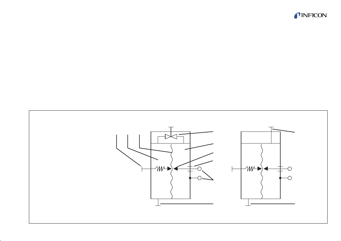
The VSC150 is a diaphragm absolute pressure switch.
He can also be used as a differential pressure switch.
Within both pressure switches there is a sensing chamber (1/2) and a reference chamber (1/5) separated by a
highly sensitive sealed diaphragm made of stainless
steel (1/3). A pin (1/6) in the reference chamber (1/5) is
led to the outside and insulated (1/7). The ground
connected diaphragm acts as the opposite contact.
This contact configuration is so designed that the diaphragm contacts the pin when it is unstressed, i. e. with
equal pressure in sensing and reference chamber.
1.3.2 Vacuum Switch Mode of Operation
For switch-point setting, the adjusting valve (1/4) between sensing chamber (1/2) and reference chamber
(1/5) is opened and closed again when the desired switching pressure is attained. If the pressure in the sensing
chamber drops below the set reference pressure by
more than 0.1 mbar, the contact opens and energizes a
heavy-duty relay in the connected SV switching amplifier.
6
tina42e1 (2005-03) VSC150.ga
Page 7
1.3.3 Switching Amplifier Mode of Operation
A switching amplifier is required for each Vacuum
Switch. The output relay supplied with heavy-duty change-over contact is energized when the pressure drops
below the value preset on the Vacuum Switch, i.e. if the
contact between diaphragm and contact pin in the reference chamber opens by flexing of the diaphragm. The
built-in slide switch (Fig. 5) must be set to the connected
type of Vacuum Switch.
7
tina42e1 (2005-03) VSC150.ga
9
(R)
(M)
10
9
(R)
(M)
8
7
6
5
4321
Fig 1 Schematic diagram of the Vacuum Switches
Key to Fig. 1
1 Adjusting Screw
2 Sensing chamber (M)
3 Diaphragm
4 Adjusting valve
5 Reference volume (R)
6 Contact pin
7 Current leadthrough
8 Electrical connection
9 Vacuum connection flange
10 Differential pressure adapter
Page 8

1.4 Equipment
1.4.1 Scope of Delivery
Part Number
Vacuum Switch VSC150 399-005
or
Switching amplifier SV 399-008
Operating Instructions tina42d1
tina42e1
1.4.2 Accessories
Clamping ring DN 16 KF, made of plastic
*)
Centering ring DN 16 KF, made of
PTFE, with FPM O-ring
*)
For pressure systems
(1000 to max. 3000 mbar abs.)
Outer centering ring
Clamping ring for ultrahigh vacuum disk DN 16 KF
*)
For floating installation
8
tina42e1 (2005-03) VSC150.ga
Page 9

2 Operation
2.1 Connection to the Vacuum System
The Vacuum Switch is mounted vertically. This ensures
that condensate can escape. Flange and gaskets must
be free of dust and grease. If the Vacuum Switch is to be
floated (electrically) it has to be separated from the
vacuum system by an insulating piece (Equipment see
Section 1.4.2).
9
tina42e1 (2005-03) VSC150.ga
50
1
105
85
21
18
2
DN 16 KF
19
119
Fig. 2 Dimensional drawing (without differential pressure adapter)
Key to Fig. 2
1 Name plate
2 Label giving the switching
threshold
Height with differential
pressure adapter 133.5 mm
Page 10

2.2 Electrical connection
Warning The terminals of the Vacuum Switch
must not be connected under any
circumstances to the mains voltage.
DANGER TO LIFE!
The housing potential may not exceed
the levels of protective low voltages
referred to ground.
10
tina42e1 (2005-03) VSC150.ga
21,5
80
4,2
15
109
121
55,5
Pg 9
Pg 9
21
50,5
163
Fig. 3 SV Switching amplifier (dimensional drawing)
Page 11
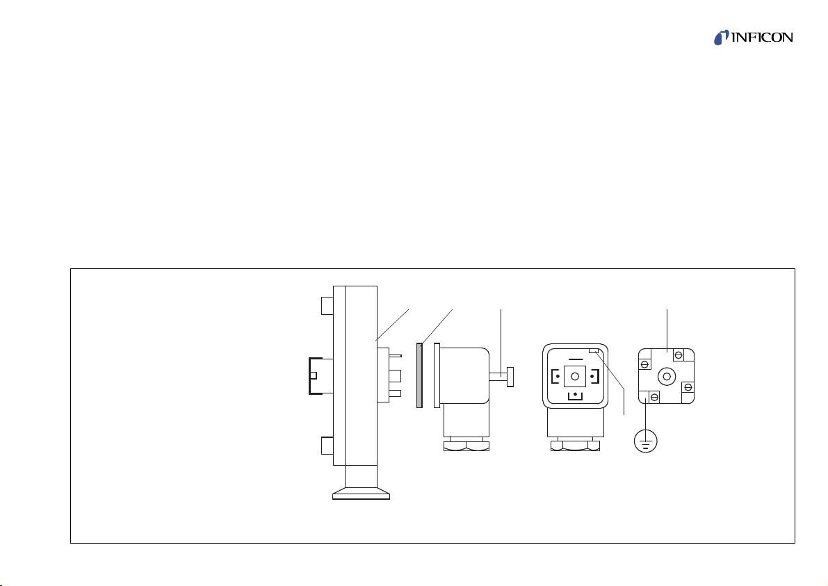
2.2.1 Connection of the Vacuum Switch
The Vacuum Switch is connected as follows:
- Unscrew fastening screw completely (4/3); lift-off
connecting box and gasket (4/2) from the Vacuum
Switch.
- Detach insert (4/4) applying a screwdriver at (4/5).
Note
Socket contact 3 (4/4) and protective ground conductor
are not connected!
See Fig. 5 for connection cables.
- Connect socket contact 1 (4/4) to terminal Aon the switching amplifier (see fig. 5).
- Connect socket contact 2 (4/4) to terminal B on the
switching amplifier (see fig. 5).
Reassemble in the reverse order.
11
tina42e1 (2005-03) VSC150.ga
Fig. 4 Vacuum Switch (electrical connection)
Key to Fig 4
1 Vacuum Switch
2 Gasket
3 Fastening serew
4 Insert
5 Point for screwdriver
Pin-out
1 Contact pin
2 Frame ground
1
2 3
1
5
4
3
2
Page 12

2.2.2 SV Switching Amplifier
The diaphragm contact in the V acuum Switch is unilaterally connected to ground and designed for a maxi-
mum load of 24 V / 10 mA.
The built-in slide switch (5/1) must be set to the connec-
ted type of pressure switch. For electrical installation the
switching amplifier SV 110 is delivered set for
220 ... 240 VAC. For mains voltages of 110 ... 130 VAC
change terminal bridge connectors as shown in Fig. 5.
When connecting to the mains the VDE 0100 regulations must be observed. The connection of the
external consumer which is to be switched is shown in
Fig. 5.
12
tina42e1 (2005-03) VSC150.ga
13
Key to fig. 5
1 Slide switch for selecting the type of
connected pressure switch
2 Signal connection (from the Vacuum Switch)
Cable cross section max. 1.5 mm
2
Cable connection PG 9
Cable diameter
(outside dia.) 4.5 to 7 mm
Fig. 5 Connection diagram of the SV switching amplifier
1
A B
VSC150
123 4 12
220....240 VAC
110....130 VAC
2
11
Page 13
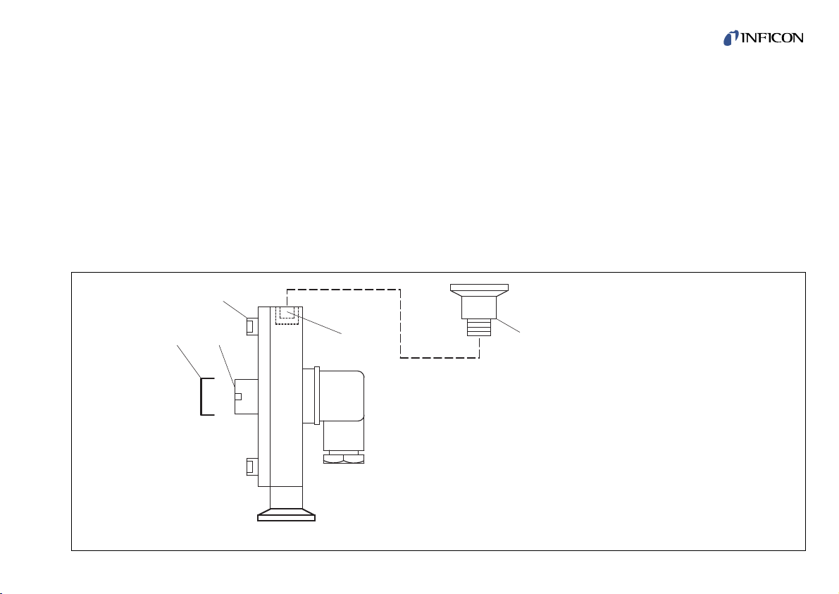
2.3 Design Versions and Switch Point Setting
A suitable vacuum gauge or pressure gauge is required
for switch point setting.
2.3.1 VSC150 Vacuum Switch
With adjustable switching pressure in the range from 0.5
to 2000 mbar.
The adjusting valve (1/4) resp. (6/4) is freely accessible
and the user may set the switching pressure to any value
within the whole range.
Note
To avoid switching errors, pressure settings below
20 mbar should only be made under clean conditions
and using dry gas.
13
tina42e1 (2005-03) VSC150.ga
1
2
3
4 5
Key to Fig. 6
1 Protection Cap
2 Adjusting screw
3 Fixing screw of housing
4 Adjusting valve
5 Differential pressure adapter
Fig 6 Vacuum Switch with differential pressure adapter
Page 14

2.3.1.1 Setting Switching Pressures Higher than 20 mbar
Condition: Correct basic adjustment of the Vacuum
Switch.
Basic adjustment of the switch in the factory provided
that at equal pressure in sensing and reference chamber
the contact is just closed.
The diaphragm (1/3) touches the contact pin (1/6) in the
reference chamber (1/5).
Check this basic adjustment.
Open adjusting valve (1/4) resp. (6/4) using an Allan key
(size across flats 5 mm) by 2 anticlockwise turns.
The relay contact via terminals 11 and 12 in the connec-
ted SV switching amplifier must now be open (Fig. 5).
If not, remove protective cap (6/1) and turn adjusting
screw (6/2) carefully clockwise till the relay is de-energized and the above-mentioned contact is open.
Then replace protective cap (6/1).
Now set desired switch point as follows:
- At first produce desired pressure in the system.
- Then close adjusting valve (6/4) turning clockwise with
the dynamometric key.
Note
The amount of torque for the adjustment valve is
Md = 3.5 to 4 Nm.
- If the pressure in the sensing chamber drops by 0.1
mbar the contact between diaphragm and contact pin
opens by flexing of the diaphragm and the relay in the
connected switching amplifier is energized.
- The switch contact on terminals 11 and 12 (see Fig. 5)
is closed.
2.3.1.2 Setting Switching Pressures Lower than 20 mbar
The procedure is basically the same as described in
2.3.1.1.
Caution However, to avoid contamination of the
reference chamber it is essential to use
only extremely dry and clean gas. Otherwise there is a risk that gas (vapor)
desorption from the chamber walls will
change the pressure in the reference
chamber.
The system must be pumped down to a pressure less
than 1·10-4mbar.
Open adjusting valve (6/4) using an Allan key (size
across flats 5 mm) by 2 anticlockwise turns.
Bake out the Vacuum Switch using strip heaters for at
least 5 to 6 hours at approx. 120 °C, while pump down
continues uninterrupted.
14
tina42e1 (2005-03) VSC150.ga
Page 15

Then admit dry protective gas to the Vacuum Switch up
to a pressure of 20 mbar, check basic adjustment of the
Vacuum Switch as described in 2.3.1.1.
Close adjusting valve turning clockwise with the dynamometric key.
Note
The amount of torque for the adjustment valve is
Md = 3.5 to 4 Nm.
Now produce desired pressure - between 0.5 and 20
mbar.
Remove protective cap (6/1) and turn adjusting screw
(6/2) carefully clockwise till the relay of the connected SV
switching amplifier is de-energized.
The contact via terminal 11 and 12 must now be open
(Fig. 5).
Then replace protective cap (6/1).
Later correction or change of the switch point between
0.5 and 20 mbar can be made anytime without readjustment of the reference pressure of 20 mbar. Such a change of the switch point is made exclusively by means of
the adjusting screw (6/2). The adjusting valve (6/4)
remains closed.
To reduce the switching pressure turn adjusting screw
(6/2) clockwise.
To increase the switching pressure turn adjusting screw
(6/2) counterclockwise.
2.4 Differential Pressure Adapter
The differential pressure adapter (6/5) consists of an
DN 16 KF flange with threaded tubulation and seal-offfitting. It is screwed onto the VSC150 Vacuum Switch
substituting the adjusting valve (6/4) and enables the
pressure switch to be used as a differential pressure
switch or a pressure balance indicator. Its operating
range is up to 2000 mbar. Differential pressures
(∆p = pR- pM) between + 5 and -20 mbar can be set up.
2.4.1 Connecting the Differential Pressure
Adapter to the Vacuum Switch
- Unscrew the adjusting valve (6/4) turning counterclock-
wise using Allan key (5 mm).
- Screw in differential pressure adapter (6/5).
Do not force!
- The connection ports of sensing chamber (1/2) and
reference chamber (1/5) are now separated.
(1/9) Connection of sensing chamber „M“;
(1/10) Connection of reference chamber „R“.
15
tina42e1 (2005-03) VSC150.ga
Page 16

Caution Only the sensing chamber can be ope-
ned for cleaning. The reference chamber can not be opened and must therefore be protected from contaminaton.
2.4.2 Switching Logic
With correct basic adjustment of the switch (see section
2.3.1.1) the following switching logic applies:
pR> pM= contact open
Relay in SV switching amplifier energized, contacts 11
and 12 closed.
pR≤ pM= contact closed
Relay in SV switching amplifier de-energized, contacts
11 and 12 open.
Correction by means of adjusting screw (6/2) see section
2.3.1.1.
2.5 Typical Applications
2.5.1 Protection of a Gate Valve which must
only be Operated when Pressure on both
Sides Becomes Equal
Assembly as shown in the diagram, Fig. 7.
Connect port (1/10) of the Vacuum Switch always to that
side where higher pressure is to be expected.
Loop the control circuit of the gate valve via the break
contact, terminals 12 and 13 (see Fig. 5), of the switching amplifier relay. The basic adjustment as described
in Section 2.3.1.1 applies to the Vacuum Switch, i.e. the
diaphragm must just touch the contact pin (6/2) see section 2.3.1.1.
When turned counterclockwise the contact opens.
When turned clockwise the contact closes.
16
tina42e1 (2005-03) VSC150.ga
Page 17

2.5.2 In a Vacuum System it must be Prevented
that in Case of Failure Gas Flows into the
Vacuum Chamber
Assembly as shown in the diagram, Fig. 7.
Also in this case, as in 2.5.1, the contact setting of the
Vacuum Switch should correspond to the basic adjustment. Control the electrically operated valve (normally
closed) via the break-contact, terminals 12 and 13 (see
Fig. 5), of the SV switching amplifier. In case of power
failure this valve closes. When the power returns the
valve is not opened before the pressure in the sensing
volume and the reference volume of the Vacuum Switch
has become equal.
2.5.3 Automatic Venting of a Vacuum Chamber
End of venting at a minimum pressure of 20 mbar below
atmospheric pressure, max. at atmospheric pressure.
Assembly as in Fig. 8.
The venting valve (normally closed) is controlled via the
make-contact of the switching amplifier relay, terminals
11 and 12 (see Fig. 5). For venting up to atmospheric
pressure the basic adjustment of the Vacuum Switch
contact applies. If venting should end before, the switching pressure can be continuously lowered by 20 mbar
17
tina42e1 (2005-03) VSC150.ga
Fig. 7 Differential pressure monitoring of a valve
Fig. 8 Automatic venting between -20 mbar and
atmospheric pressure
M
VSC 150
SV
R
R
VSC 150
SV
M
Page 18

max. turning the adjusting screw (6/2) clockwise.
2.5.4 Automatic Venting of a Vacuum Chamber
to a Slight Overpressure
Assembly as in Fig. 9.
Loop the control circuit of the venting valve via the break
contact of the switching amplifier relay, terminals 12 and
13 (see Fig. 5). The switching pressure can be raised by
20 mbar max. above atmospheric pressure by turning
the adjusting screw (6/2) clockwise.
2.5.5 Differential Pressure Monitoring, Positive
and Negative Going
In an annealing plant with „holding vacuum“ pump down
and venting of the annealing pot and the vacuum furnace must be regulated so that the differential pressures
in both directions will not exceed 10 mbar (Assembly as
shown in Fig. 10).
Starting from the basic adjustment set the two Vacuum
Switches by turning the adjusting screw (6/2) clockwise
so that at a pressure of 10 mbar in the reference chamber against the pressure in the sensing chamber the
switch contact opens by flexing of the diaphragm. Control venting valves and pump valves each via the break
18
tina42e1 (2005-03) VSC150.ga
Fig. 10 Differential pressure monitoring, positive and
negative going
Fig. 9 Automatic venting between atmospheric pressure
and + 20 mbar
M
VSC 150
SV
R
M
VSC 150
SV SV
R
R
VSC 150
M
Oven
Crucible
Page 19

contact, terminals 12 and 13, of the two SV switching
amplifiers.
As soon as during pump down or venting the differential
pressure between annealing pot and vacuum furnace in
either direction exceeds 10 mbar, the respective pump
valve or venting valve is closed. The valves open again
as soon as the differential pressure has dropped below
the set switching pressure. Switching pressures can be
varied between 0.5 and 20 mbar by means of the adjusting screw (6/2).
3 Maintenance
For the pressure switches maintenance work is normally not nesessary. Slight contamination of the sensing
chamber does not affect the switching performance and
accuracy. If for one reason or other cleaning should
become necessary, observe Sections 3.1 or 3.2.
3.1 Cleaning the Sensing Chamber
- Remove protection cap (6/1).
- Unscrew adjusting screw (6/2) by turning counterclockwise and extract the complete setting mechanism (ball
and compression spring).
- Unscrew the three housing screws (6/3) and open the
sensing chamber.
Caution Do not exert pressure on the diaphragm.
Do not use any mechanical cleaning
means like emery paper, steel wool or
steel brushes. Cleanse with solvents
- petroleum ether, benzin or alcohol and dry. Replace gasket, if necessary.
19
tina42e1 (2005-03) VSC150.ga
Page 20

Note
- Reassemble the setting machanism in the order compression spring, ball and adjusting screw.
- When screwing in the adjusting screw grease the
O-ring slightly with Lithelen.
Reassemble Vacuum Switch. Set adjusting screw (6/2)
as described in section 2.3.
3.2 Cleaning the reference chamber
Cleaning of the reference chamber is only possible in
the VSC150 Vacuum Switch if the latter is used as a differential pressure switch. The reference chamber cannot
be opened but can only be cleansed with solvents.
Proceed as follows:
- Unscrew the differential pressure adapter (6/5) and
inject solvent by means of a syringe. Let solvent act for
a while, shake and pour out.
- Repeat this procedure several times (if nesessary).
Then screw in differenbal pressure adapter again,
tightening uniformly!
- Dry the reference chamber by evacuating with a vacuum pump.
- Readjustment of the basic setting is only nesessary if
the measurement chamber has been opened.
3.3 Service at INFICON
Warning Contaminated products (e.g. radioac-
tive, toxic, caustic or microbiological
hazard) can be detrimental to health and
environment.
Products returned to Inficon should preferably be free of
harmful substances. Adhere to the forwarding regulations of all involved countries and forwarding companies
and enclose a duly completed declaration of contamination (see Annex).
Products that are not clearly declared as „free of harmful
substances“ are decontaminated at the expense of the
customer.
Products not accompanied by a duly completed declaration of contamination are returned to the sender at his
own expense.
20
tina42e1 (2005-03) VSC150.ga
Page 21

4 Disposal
Warning Contaminated parts
Contaminated parts can be detrimental
to health and environment.
Before beginning to work, find out whether any parts are
contaminated. Adhere to the relevant regulations and
take the necessary precautions when handling contaminated parts.
Warning Substance detrimental to the environ-
ment
Products or parts thereof (mechanical
and electric components, operating
fluids etc.) can be detrimental to the
environment.
Dispose of such substance in accordance with the relevant local regulations.
Separating the components
After disassembling the product, separate its components according to the following criteria:
Contaminated components
Contaminated components (radioactive, toxic, caustic
or biological hazard etc.) must be decontaminated in
accordance with the relevant national regulations,
separated according to their materials, and disposed
of.
Other components
Such components must be separated according to
their materials and recycled.
21
tina42e1 (2005-03) VSC150.ga
Page 22

22
tina42e1 (2005-03) VSC150.ga
EEC Declaration of Conformity
We, INFICON, hereby declare that the equipment mentioned below complies with the provisions of the Directive relating to electrical equipment designed for use within certain voltage limits 73/23/EEC and the Directive
relating to electromagnetic compatibility 89/336/EEC.
Product:
Vacuum Switch VSC150
Part Number
399-005
Standards
Harmonized and international / national standards and
specifications:
• EN 61000-6-2
• EN 61000-6-3
• EN 61010
• VDE 0411 Teil 1
• VDE 0839 Teil 81-2
• VDE 0839 Teil 82-2
Balzers, 18 March 2005
—————————————————————
Reto Süssli, Product Marketing Manager
Balzers, 18 March 2005
—————————————————————
Dr. Georg Sele, Technical Support Manager
Quality Representative
Page 23

23
tina42e1 (2005-03) VSC150.ga
The service, repair, and/or disposal of vacuum equipment and components will only be carried out if a correctly completed declaration has
been submitted. Non-completion will result in delay.
This declaration may only be completed (in block letters) and signed by authorized and qualified staff.
Description of product
Type
Part number
Serial number
Reason for return
Legally bind ing declaration:
W e hereby declare that the information on this form is complete and accurate and that we will assume any further costs that may
arise. The contaminated product w ill be dispatched in a ccordance with the applicable regulations.
Or ganization/company
Address Post code, place
Phone Fax
Email
Name
Date and legally b inding signature Company stamp
Copies:
Origina l for addresee - 1 copy for accompanying documents - 1 cop y for file of sender
Operating f luid(s) used
(Must be drained before shipping.)
Harmful substances, gases and/or by-products
Please list all substances, gases, and by-products which the product may have come into contact with:
Trade/product name
Chemical name
(or symbol )
Precaution s associated
with substance
Action if human contact
The product is free of any sub-
stances which are damaging to
health. ye s
q
Used in copper process
no
q
yes
q
Seal product in plastic bag and
mark it with a corresponding label.
This form can be down loaded
from our website.
2) Products thus contami-
nated wil l not be ac-
cepted without written
evidence of decontami-
nation.
1) or not containing any amount
of haz ardous residues that
exceed the permissible ex-
posure limits
Process related contamination of pro duct:
to xic no
q
1) yes
q
caustic no
q
1) yes
q
biological hazard no
q
yes
q
2)
explosive no
q
yes
q
2)
ra dioactive no
q
yes
q
2)
other harmful substances no
q
1) yes
q
Declaration of ContaminationDeclaration of Contamination
Page 24

INFICON Ltd.
LI-9496 Balzers, Principality of Liechtenstein
Tel.: +423 388 3111 Fax: +423 388 3700 E-mail: reachus@inficon.com
UNITED STATES FRANCE GERMANY LIECHTENSTEIN UNITED KINGDOM CHINA JAPAN KOREA SINGAPORE TAIWAN
Due to INFICON s continuing program of product improvements, specifications are subject to change without notice.
Visit our website for contact information and other sales offices worldwide.
www.inficon.com
 Loading...