

Page 1
Vacuum Switch
VSA200, VSD200
Operating Manual
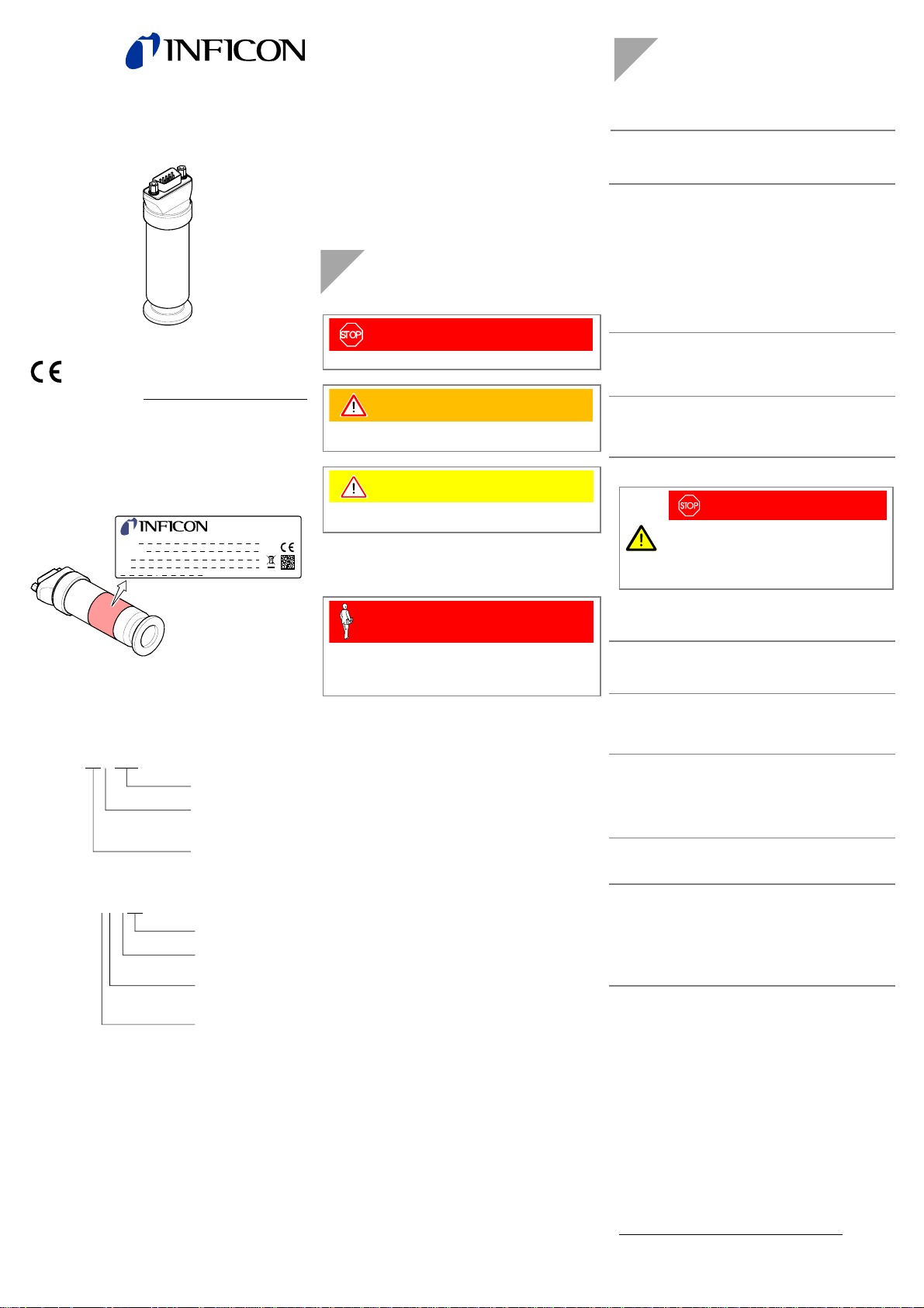
Product Identification
In all communications with INFICON, please specify the information on the product nameplate. For convenient reference copy that information into the space provided below.
Validity
This document applies to products with the following part
numbers:
VSA200
3SA1-xxx-xxx0
VSD200
3SD1-Mxx-xxx0
The part number (PN) can be taken from the product nameplate.
If not indicated otherwise in the legends, the illustrations in
this document correspond to the vacuum switch with vacuum
connection DN 16 ISO-KF. They apply to vacuum switches
with other vacuum connection by analogy.
We reserve the right to make technical changes without prior
notice.
All dimensions in mm.
Incl. EC Declaration of Conformity
tina65e1 (2011-01)
Model:
Set point:
PN:
SN:
V W
Set-point value
Flange
Setpoint value
Flange
LI-9496 Balzers
1 ⇒ DN 16 ISO-KF
C
⇒
4 VCR male
4 VCR female
D
⇒
Unit
F5 ⇒ 1000
G6 ⇒ 1100 mbar
Sign
A ⇒ +
B ⇒ –
1 ⇒ DN 16 ISO-KF
C
⇒
D
⇒
Unit
5
⇒
6 ⇒ mbar
4 VCR male
4 VCR female
Torr
Torr
Intended Use
The vacuum switches have been designed for the use in
vacuum systems as absolute pressure switch (VSA200) or as
differential pressure switch (VSD200) in different measurement ranges.
Trademark
VCR® Swagelok Marketing Co.
Safety
Symbols Used
DANGER
Information on preventing any kind of physical injury.
WARNING
Information on preventing extensive equipment and environmental damage.
Caution
Information on correct handling or use. Disregard can lead
to malfunctions or minor equipment damage.
Personnel Qualifications
Skilled personnel
All work described in this document may only be carried out
by persons who have suitable technical training and the
necessary experience or who have been instructed by the
end-user of the product.
General Safety Instructions
• Adhere to the applicable regulations and take the necessary precautions for the process media used.
Consider possible reactions between the materials and the
process media.
• Adhere to the applicable regulations and take the necessary precautions for all work you are going to do and consider the safety instructions in this document.
• Before beginning to work, find out whether any vacuum
components are contaminated. Adhere to the relevant regulations and take the necessary precautions when handling contaminated parts.
Communicate the safety instructions to all other users.
Liability and Warranty
INFICON assumes no liability and the warranty becomes null
and void if the end-user or third parties
• disregard the information in this document
• use the product in a non-conforming manner
• make any kind of interventions (modifications, alterations
etc.) on the product
• use the product with accessories not listed in the product
documentation.
The end-user assumes the responsibility in conjunction with
the process media used.
Gauge failures due to contamination or wear and tear, are not
covered by the warranty.
Technical Data
Measurement range
VSA200 (absolute)
VSD200 (relative to atm) -100 … +50 mbar, Torr
Setpoint (setting range)
VSA200
VSD200 -99 … +46 mbar, Torr
Switching contact changeover contact, floating
Hysteresis 2 % above setpoint
Contact rating
Switching
characteristics
1)
Accuracy ≤0.5 % F.S.
Resolution 10 bit
Switching frequency 0.5 Hz
Response time ≤45 ms
Temperature effect on zero
and span
Long-term stability ≤±0.5 % F.S. / a
Effect supply voltage ≤±0.005 % F.S. / V
Starting time 1 s
Service live
Electronic
Relay
Supply
DANGER
The vacuum switch may only be connected to
power supplies, instruments or control devices
that conform to the requirements of a grounded
extra-low voltage (SELV). The connection to the
vacuum switch has to be fused.
Supply voltage +14 … +30 VDC
Current consumption ≤15 mA
Power consumption ≤0.5 W
Electrical connection D-Sub, 9 pin, male
Cable 6 pin plus shielding
Cable length ≤100 m (8×0.14 mm
Materials exposed to
vacuum
Housing
Diaphragm
Internal volume
DN 16 ISO-KF
®
4 VCR
Admissible pressure (abs.)
Admissible temperatures
VSA200
VSD200
Operation
Storage
Relative humidity ≤80 at temperatures up to
Use indoors only, altitude up to
Mounting orientation any
Degree of protection IP40
1100 mbar (F.S.)
1000 Torr (F.S.)
30 … 1060 mbar
20 … 970 Torr
30 V, 1 A DC
125 V, 0.3 A AC
Low Trip Point
≤±0.02 % F.S. / 1K
8
>1×10
cycles
25'000 h
6
>3×10
cycles
1.4571, 1.4404
1.4435
3
2.81 cm
3
0.93 cm
5 bar
2 bar
0 … +70 °C
–40 … +80
≤+31 °C, decreasing to 50
at +40 °C
4000 m NN
2
)
1)
The switching characteristics and the setpoint can be
programmed via the serial interface (pin 6, 7, 8).
Page 2
Dimensions [mm]
≈60
5.5
34
ø30
101.5
ø26.5
117
104.5
10
DN 16 ISO-KF
Weight
9
4 VCR
female
≈140 g
Installation
Vacuum Connection
DANGER
DANGER: overpressure in the vacuum system
>1 bar
Injury caused by released parts and harm
caused by escaping process gases can result if
117.5
24.2
4 VCR
male
clamps are opened while the vacuum system is
pressurized.
Do not open any clamps while the vacuum system is pressurized. Use the type of clamps which
are suited to overpressure.
DANGER
DANGER: overpressure in the vacuum system
>2.5 bar
KF connections with elastomer seals (e.g.
O-rings) cannot withstand such pressures. Process media can thus leak and possibly damage
your health.
Use O-rings provided with an outer centering
ring.
DANGER
DANGER: protective ground
Incorrectly grounded products can be extremely
hazardous in the event of a fault.
The gauge must be electrically connected to the
grounded vacuum chamber. This connection
must conform to the requirements of a protective
connection according to EN 61010:
®
• VCR
connections fulfill this requirement.
• For gauges with a KF connection, use a con-
ductive metallic clamping ring.
Caution
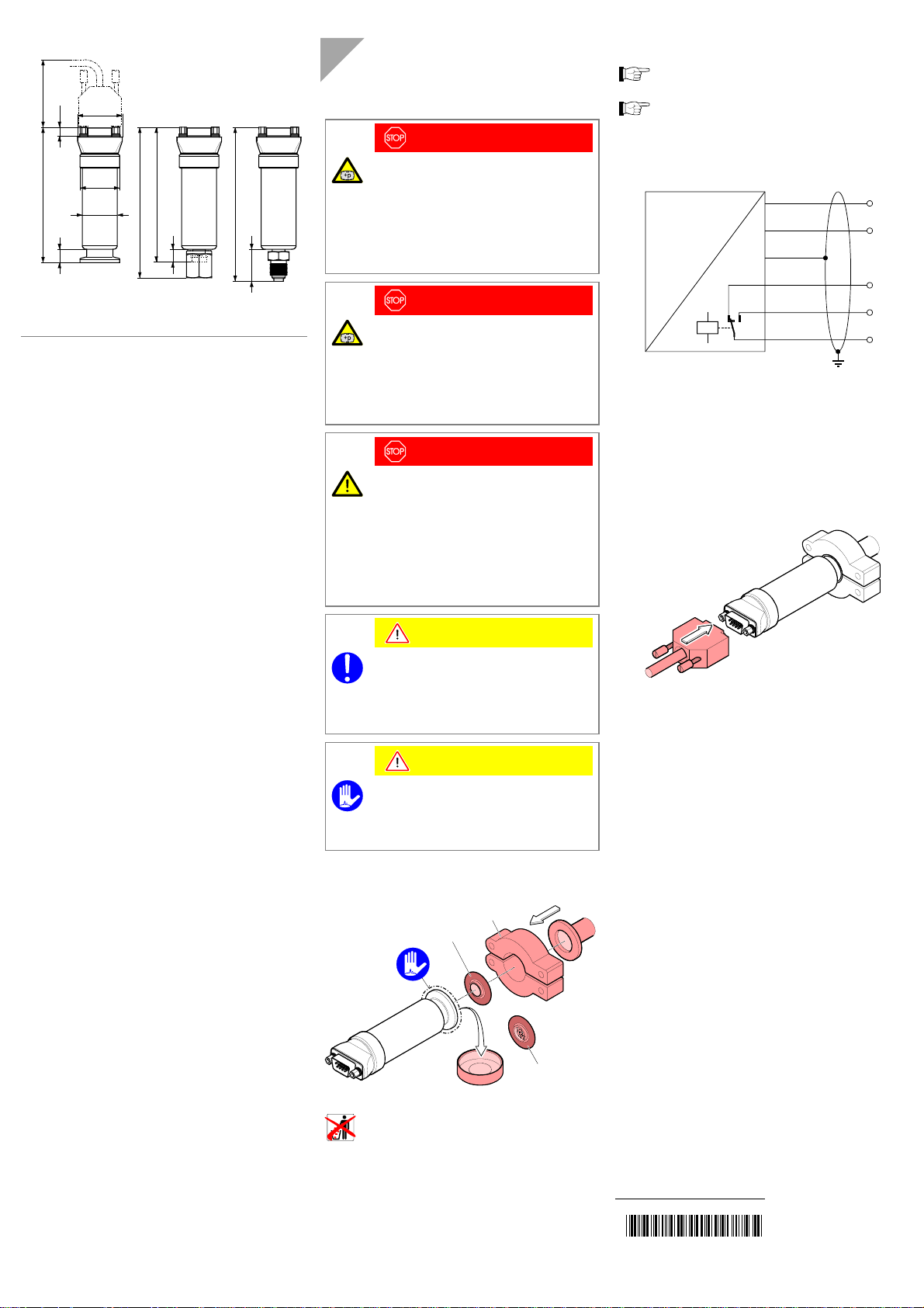
Power Connection
Make sure the vacuum connection is properly made
(→ "Vacuum Connection").
Before connecting or disconnecting the product, turn
off the control system.
n If no sensor cable is available, make one according to
the following diagram.
p
9
U
Pin 1 Supply common, GND
Pin 2 Supply +14V ... 30 V
Pin 3 Relay n.o.
Pin 4 Relay common
Pin 5 Relay n.c.
Pin 6 Internal common RxD
Pin 7 Internal common TxD
Pin 8 Internal common (com)
Pin 9 Housing (Chassis Ground)
o Connect the cable to the vacuum switch.
2
UB+
1
–
U
B
5
NC
3
NO
4
C
Caution: vacuum component
Dirt and damages impair the function of the vac-
uum component.
When handling vacuum components, take ap-
propriate measures to ensure cleanliness and
prevent damages.
Caution
Caution: dirt sensitive area
Touching the product or parts thereof with bare
hands increases the desorption rate.
Always wear clean, lint-free gloves and use
clean tools when working in this area.
Remove the protective lid and install the product to the vacuum system.
Clamp
Seal with centering ring
Keep the protective lid.
or
Seal with
centering ring
and filterProtective lid
Original: German tina65d1 (2011-01)
t i na65e1
(2011-01)
Page 3

Operation
The product is ready for operation as soon as it has been
installed.
The gauge is factory calibrated while "standing upright". Due
to changing the mounting orientation, a low zero drift could
occur (0.05 % F.S.).
Setpoint, Switching Characteristics
The setpoint can be read and set to any pressure within the
setting range of the vacuum switch with the communication
software (
→ [1]).
The switching characteristics of the setpoint can be programmed with the communication software (
Low Trip Point (default)
If the pressure in the vacuum system is lower than the setpoint, the relay is closed.
Measurement signal
(Pressure p)
Setpoint
Off
→ [1]).
t
n
e
m
e
r
u
s
a
e
M
Hysteresis
(2% of threshold)
Threshold value
OffOn
e
u
l
a
v
Time t
Deinstallation
DANGER
DANGER: contaminated parts
Contaminated parts can be detrimental to health
and environment.
Before beginning to work, find out whether any
parts are contaminated. Adhere to the relevant
regulations and take the necessary precautions
when handling contaminated parts.
Caution
Caution: vacuum component
Dirt and damages impair the function of the vac-
uum component.
When handling vacuum components, take ap-
propriate measures to ensure cleanliness and
prevent damages.
Caution
Caution: dirt sensitive area
Touching the product or parts thereof with bare
hands increases the desorption rate.
Always wear clean, lint-free gloves and use
clean tools when working in this area.
n Vent the vacuum system.
o Put the vacuum switch out off operation.
p Unplug the sensor cable.
Before connecting or disconnecting the pro-
duct, turn off the control system.
Maintenance, Repair
Under clean operating conditions, the product requires no
maintenance.
The product is factory calibrated while "standing upright". Due
to long time operation, contamination, or operation in other
mounting orientation a zero adjustment may become
necessary.
We recommend returning the product to your local
INFICON service center for service.
Vacuum switch failures due to contamination or
wear and tear are not covered by the warranty.
INFICON assumes no liability and the warranty becomes null
and void if any repair work is carried out by the end-user or
third parties.
Returning the Product
WARNING
WARNING: forwarding contaminated products
Contaminated products (e.g. radioactive, toxic,
caustic or microbiological hazard) can be detrimental to health and environment.
Products returned to INFICON should preferably
be free of harmful substances. Adhere to the forwarding regulations of all involved countries and
forwarding companies and enclose a duly completed declaration of contamination
*)
Form under www.inficon .com
Products that are not clearly declared as "free of harmful substances" are decontaminated at the expense of the customer.
Products not accompanied by a duly completed declaration of
contamination are returned to the sender at his own expense.
*)
.
q Remove the vacuum switch from the vacuum system
and install the protective lid.
Schutzkappe
Page 4

Disposal
DANGER
DANGER: contaminated parts
Contaminated parts can be detrimental to health
and environment.
Before beginning to work, find out whether any
parts are contaminated. Adhere to the relevant
regulations and take the necessary precautions
when handling contaminated parts.
WARNING
N
WARNING: substances detrimental to the environment
Products or parts thereof (mechanical and electric components, operating fluids etc.) can be detrimental to the environment.
Dispose of such substances in accordance with
the relevant local regulations.
Separating the components
After disassembling the product, separate its components
according to the following criteria:
• Contaminated components
Contaminated components (radioactive, toxic, caustic, or
biological hazard etc.) must be decontaminated in accordance with the relevant national regulations, separated
according to their materials, and disposed of.
• Other components
Such components must be separated according to their
materials and recycled.
Accessories
Ordering number
Communication adapter with USB
connector (2 m)
303-336
Further Information
[1] www.inficon.com
Communication software VSA200, VSD200
EC Declaration of Conformity
Products
We, INFICON, hereby declare that the equipment mentioned below complies with the provisions of the Directive relating to electromagnetic compatibility 2004/108/EC.
Vacuum Switch
VSA200, VSD200
Standards
Harmonized and international/national standards and specifications:
• EN 61326-1:1997 + A1:1998 + A2:2001 + A3:2003
(EMC requirements for electrical equipment for measurement,
control and laboratory use)
Manufacturer / Signatures
INFICON AG, Alte Landstraße 6, LI-9496 Balzers
17 January 2010 17 January 2010
Dr. Urs Wälchli
Managing Director
Alex Nef
Product Manager
LI–9496 Balzers
Liechtenstein
Tel +423 / 388 3111
Fax +423 / 388 3700
reachus@inficon.com
www.inficon.com
 Loading...