

Page 1

Operating
M
a
r
m
a
n
5
l
G
o
n
Incl. EU Declar
anual
ation of Confor
ity
Singl
Cont
VGC50
e-Ch
ol U
1, VGC
nne
its
02, V
, Tw
C503
-Channel & Th
ree-Chan
el
tina96e1-b (20
16-12)
1
Page 2
Prod
u
V
f
n
T
T TIf
f
o
V
U
W
A
c
-
-
-
e
t
t
l
g
e
N
c
o
m
m
t
5
o
e
a
a
-
C
-
t
h
h
n
a
e
n
U
c
t
s
5
t
o
c
m
a
a
o
t
alid
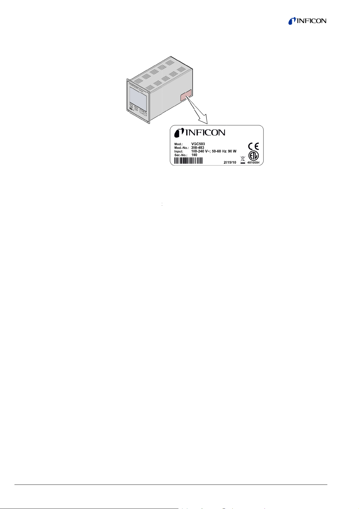
ct Identi
ity
ication
I
all communi
n
meplate:
his document
398
398
398
he part numb
ations with I
Spe
applies to pr
481
482
483
er (Mod.-No.)
FICON, plea
imen namepl
ducts with p
(VGC501, Single
(VGC502, Two-
(VGC503, Three
can be found
e specify th
te
rt numbers:
Channel Control
hannel Control U
Channel Control
on the produ
information
Unit)
nit)
Unit)
t nameplate.
n the produc
his manual is
your unit doe
uipped with
e
not indicated
I
rrespond to
c
GC501 (Sing
nit) by analo
e reserve th
ll dimensions
based on fir
s not work as
he above fir
otherwise in
he unit VGC
e-Channel C
y.
right to mak
are indicated
ware version
described in
ware version
he legends, t
03 (Three-C
ntrol Unit) a
technical ch
in mm.
V1.04.
his documen
(→ 58).
e illustration
annel Control
d to the VGC
nges withou
, please che
in this docu
Unit). They
02 (Two-Ch
prior notice.
k that it is
ent
pply to the
nnel Control
2
tina96e1-b (2016-12)
VGC501_VGC502_VGC503.
m
Page 3

Intended Use
Scope of Delivery
The Control Units VGC501, VGC502 and VGC503 are used together with
INFICON gauges for total pressure measurement. All products must be operated in
accordance with their respective operating manuals.
The scope of delivery consists of the following parts:
1× Control Unit
1× Power cord (country-specific)
1× Rubber bar
2× Rubber feet
4× Collar screws
4× Plastic sleeves
1× CD-ROM (manuals, tools, …)
1× EU Declaration of Conformity
1× Installation Manual
tina96e1-b (2016-12) VGC501_VGC502_VGC503.om 3
Page 4

Contents
Product Identification 2
Validity 2
Intended Use 3
Scope of Delivery 3
Contents 4
1 Safety 6
1.1 Symbols Used 6
1.2 Personnel Qualifications 6
1.3 General Safety Instructions 7
1.4 Liability and Warranty 7
2 Technical Data 8
3 Installation 12
3.1 Installation, Setup 12
3.1.1 Rack Installation VGC501 12
3.1.2 Rack Installation VGC502, VGC503 15
3.1.3 Installation in a control panel 16
3.1.4 Use as Desk-Top Unit 17
3.2 Mains Power Connector 18
3.3 Gauge Connectors CH 1, CH 2, CH 3 19
3.4 CONTROL Connector VGC501 21
3.5 CONTROL Connector VGC502, VGC503 22
3.6 RELAY Connector VGC502, VGC503 22
3.7 Interface Connector USB Type B 24
3.8 Interface Connector USB Type A 24
3.9 Interface Connector Ethernet 25
4 Operation 26
4.1 Front panel 26
4.2 Turning the VGC50x On and Off 28
4.3 Operating Modes 28
4.4 Measurement Mode 31
4.5 Parameter Mode 33
4.5.1 Switching Function Parameters 34
4.5.2 Gauge parameters 38
4.5.3 Gauge Control 46
4.5.4 General Parameters 50
4.5.5 Test Parameters 58
4.5.6 Data Logger Mode 61
4.5.7 Parameter Transfer Mode 63
5 Communication Protocol (Serial Interface) 65
5.1 Data Transmission 66
5.2 Communication Protocol 67
5.3 Mnemonics 68
5.4 Measurement Mode 70
5.5 Switching Function Parameters 76
5.6 Gauge Parameters 77
5.7 Gauge Control 84
5.8 General Parameters 85
5.9 Data Logger Parameters 91
5.10 Parameter Transfer 92
5.11 Test Parameters 92
5.12 Further 97
5.13 Example 98
6 Maintenance 99
7 Troubleshooting 100
8 Repair 101
9 Accessories 101
10 Storage 101
11 Disposal 101
4 tina96e1-b (2016-12) VGC501_VGC502_VGC503.om
Page 5

Appendix 102
A: ConversionTables 102
B: Firmware Update 103
C: Ethernet Configuration 106
C 1: Connect the VGC50x to a Network 106
C 2: Connect the VGC50x to a Computer 107
C 3: Ethernet Configuration Tool 107
D: Literature 110
ETL Certification 112
EU Declaration of Conformity 113
For cross-references within this document, the symbol (→ XY) is used; for cross-
references to further documents listed under ‘Literature’, use is made of the symbol
(→ [Z]).
tina96e1-b (2016-12) VGC501_VGC502_VGC503.om 5
Page 6

1
S
S
S
F
P
U
r
b
l
s
a
I I I
m
A
h
i
A
n
W
n
a
n
e
s
n
e
e
r
t
a
e
d
y
y
y
a
n
o
n
o
y
D
m
n
n
l
e
d
n
o
h
o
1.1
afety
ymbols
ymbols for
sed
esidual risk
D
NGER
urther sym
ols
nformation o
nformation o
nformation o
inor equipm
The
The
The
Pre
preventing
ARNING
preventing
C
ution
correct han
ent damage.
lamp / displa
lamp / displa
lamp / displa
s the key (ex
ny kind of ph
xtensive equi
ling or use.
is lit.
flashes.
is off.
mple: para
sical injury.
pment and e
isregard can
eter key).
vironmental
lead to malfu
amage.
ctions or
1.2
ersonne
Qualific
tions
Do
<
……> Lab
Skill
ll work desc
ave suitable
nstructed by
ot press any
ling
d person
ibed in this d
technical trai
he end-user
key.
el
cument may
ing and the
f the product
only be carri
ecessary exp
d out by pers
erience or w
ns who
o have been
6
tina96e1-b (2016-12)
VGC501_VGC502_VGC503.
m
Page 7

C
1.3 Gen
e
u
n
y
W
c
o
t
e
t
E
a
o
R
w
d
e
t
e
i
f
o
n
g
i
d
e
a
n
t
m
(
s
e
y
n
t
i
o
s
,
p
i
e
n
e
g
u
t
n
r
e
s
p
d
a
t
o
Instr
ral Safet
ctions
Adhere
work yo
to the applic
u are going t
ble regulatio
do and cons
s and take th
der the safet
necessary
instructions
recautions fo
n this docum
all
nt.
DANGER
Disco
necting dev
ice
The dis
user.
To disc
DANGE
Contact
introduce
Make sur
trate into
onnecting d
nnect the un
: mains volta
ith live parts
or any liqui
no objects
he equipmen
vice must be
t from the m
e
s extremely h
s penetrate i
nter through
.
readily identif
ins supply, y
azardous wh
to the unit.
he louvers a
iable by and
u must unplu
n any object
d no liquids
asily reache
the mains c
are
ene-
by the
ble.
1.4 Liabi
lity and
arranty
Disconn
acc. to
Commu
INFICO
user or
• disre
• use t
• mak
• use t
men
ecting device
N 61010-1
nicate the sa
N assumes n
third parties
gard the infor
he product in
any kind of i
he product wi
ation.
ety instructio
liability and
mation in this
a non-confor
nterventions
th accessorie
s to all other
he warranty i
document
ing manner
modifications
not listed in
users.
s rendered n
, alterations e
the correspo
ll and void if
c.) on the pr
ding product
he end-
duct
docu-
tina96e1-b (2016-12) VG
501_VGC502_VGC503.om
7
Page 8

2 Technical Data
Mains specifications
Ambience
Gauge connections
Gauge supply
Voltage 100 … 240 V (ac) ±10%
Frequency 50 … 60 Hz
Power consumption
VGC501
VGC502
VGC503
≤45 W
≤65 W
≤90 W
Overvoltage category II
Protection class 1
Connection European appliance connector IEC 320 C14
Temperature
Storage
Operation
–20 … +60 °C
+ 5 … +50 °C
Relative humidity ≤80% up to +31 °C,
decreasing to 50% at +40 °C
Use indoors only
max. altitude 2000 m NN
Pollution degree II
Degree of protection IP30
Number
VGC501
VGC502
VGC503
Gauge connections per channel
1
2
3
RJ45 (FCC68), 8-pin (→ 20)
D-Sub, 15-pin, female (→ 20)
(connected in parallel)
Compatible gauges
Pirani PSG400, PSG400-S, PSG100-S, PSG101-S,
PSG500, PSG500-S, PSG502-S, PSG510-S,
PSG512-S, PSG550, PSG552, PSG554
Pirani / Capacitance PCG400, PCG400-S, PCG550, PCG552,
PCG554
Cold cathode PEG100, MAG500, MAG504
Cold cathode / Pirani MPG400, MPG401, MPG500, MPG504
Hot ionization / Pirani BPG400, BPG402, HPG400
Capacitance CDG020D, CDG025, CDG025D,
CDG025D-X3, CDG045, CDG045-H,
CDG045D, CDG045D2, CDG045Dhs,
CDG100, CDG100D, CDG100D2,
CDG100Dhs, CDG160D, CDG200D
Hot ionization / Capacitance /
BCG450
Pirani
Voltage +24 V (dc) ±5%
Ripple <±1%
Current 0 … 1 A (per channel)
Power 25 W (per channel)
Fuse protection 1.5 A (per channel) with PTC element, self-
resetting after turning the unit off or disconnecting the gauge. The supply conforms to the
grounded protective extra low voltage requirements.
8 tina96e1-b (2016-12) VGC501_VGC502_VGC503.om
Page 9

g
Operation
Measurement values
Switching functions
Switching function relays
Error signal
Front panel
VGC501
VGC502, VGC503
via 3 keys
via 4 keys
Remote control via USB type B interface
via Ethernet interface
Measurement ranges
Measurement error analog
Gain error
depending on gauges (→ [1] … [27])
≤0.01% F.S. (typical)
≤0.10% F.S. (over temperature range, time)
Offset error ≤0.01% F.S. (typical)
≤0.10% F.S. (over temperature range, time)
Measurement rate analog ≥100 / s
Display rate ≥10 / s
Filter time constant
Slow
Normal
Fast
= 0.02 Hz)
8 s (f
g
800 ms (f
160 ms (f
= 0.2 Hz)
g
= 1 Hz)
Measurement units mBar, hPa, Torr, Pa, Micron, V
Offset correction for linear gauges
Calibration factor 0.10 … 10.00
A/D converter resolution 0.001% F.S.
(the measurement values of BPG, HPG, BCG
and CDGxxxD are transmitted digitally)
Number
VGC501
VGC502
VGC503
2
4 (user-assignable)
6 (user-assignable)
Reaction delay ≤10 ms, if switching threshold close to meas-
urement value (for larger differences consider
filter time constant)
Adjustment range
depending on gauge (→ 36, 37)
Hysteresis ≥1% F.S. for linear gauges,
≥10% of measurement value for logarithmic
gauges
Contact type floating changeover contact
Load max. 60 V(dc), 30 W (ohmic)
30 V(ac), 1 A (ohmic)
Service life
Mechanical
Electrical
Contact positions
Connector
VGC501 (CONTROL)
8
cycles
1×10
5
1×10
cycles (at max. load)
→ 23
D-Sub appliance connector, male, 15-pin
(pin assignment → 21)
VGC502, VGC503 (RELAY) D-Sub appliance connector, female, 25-pin
(pin assignment → 22)
Number 1
Reaction time ≤10 ms
tina96e1-b (2016-12) VGC501_VGC502_VGC503.om 9
Page 10

Error signal relay
Analog outputs
Recorder output
(VGC502, VGC503 only)
USB Type A interface
USB Type B interface
Ethernet interface
Contact type floating normally open contact
Load max. 60 V(dc), 0.5 A, 30 W (ohmic)
30 V(ac), 1 A (ohmic)
Service life
Mechanical
Electrical
Contact positions
Connector
VGC501 (CONTROL)
8
cycles
1×10
5
1×10
cycles (at max. load)
→ 23
D-Sub appliance connector, male, 15-pin
(pin assignment → 21)
VGC502, VGC503 (RELAY)
D-Sub appliance connector, female, 25-pin
(pin assignment → 22)
Number
VGC501
VGC502
VGC503
1
2 (1 per channel)
3 (1 per channel)
Voltage range –5 … +14.5 V (dc)
If no gauge is connected, +14.5 V (dc) is output
Deviation from display value ±20 mV
Output resistance
Measuring signal vs. pressure
CONTROL connector
VGC501
<50 Ω
depending on gauge (→ [1] … [27])
D-Sub appliance connector, male, 15-pin
(pin assignment → 21)
VGC502, VGC503 D-Sub appliance connector, male, 9-pin
(pin assignment → 22)
Number
1
Voltage range 0 … +10 V (dc)
Resolution 1 mV
Accuracy ±20 mV
Internal resistance
<50 Ω
Measuring signal vs. pressure programmable
CONTROL connector D-Sub appliance connector, male, 9-pin
(pin assignment → 22)
Protocol FAT file system
file handling in ASCII format
Protocol ACK/NAK, ASCII with 3-character mnemonics
Data format bi-directional data flow, 1 start bit, 8 data bits,
1 stop bit, no parity bit, no handshake
Transmission rate 9600, 19200, 38400, 57600, 115200
Protocol ACK/NAK, ASCII with 3-character mnemonics,
Data format bi-directional, 1 start bit, 8 data bits, 1 stop bit,
no parity bit, no handshake
Transmission rate 9600, 19200, 38400, 57600, 115200
IP Address
DHCP (default) or manual setting (→ 106)
MAC Address readable via "MAC" parameter
10 tina96e1-b (2016-12) VGC501_VGC502_VGC503.om
Page 11

C
Dimens
V
1
V
2
o
1
2
3
o
a
ions [mm]
GC50
Use
Weight
GC50
For inc
VGC50
VGC50
VGC50
, VGC503
rporation int
1
a rack or control panel or
0.85 kg
1.10 kg
1.14 kg
s a desk-top unit
tina96e1-b (2016-12) VG
501_VGC502_VGC503.om
11
Page 12

n
o
a
VG
T
TDw
n
e
e
t
mope
i
o
h
sacc
k
u
a
p
n
h
o
G
t
u
a
a
e
G
c
e
a
a
d
G
p
b
u
n
s
t
a
g
g
w
h
o
n
s
a
m
n
a
o
p
c
a
p
a
b
i
C
o
-
3 I
3.1 I
3.1.1
stallati
nstallatio
Rack Inst
n
n, Setup
llation
C501
he unit is suit
d
sk-top unit.
he unit is des
IN 41 494. F
ith it.
Th
unit may onl
trai
ning and the
the
end-user of t
d for incorp
Pu
ting a produc
tre
ely hazardo
ration and m
igned for inst
r this purpos
Skilled
DAN
ersonnel
y be installed
ecessary ex
e product.
ration into a 1
ER
which is visi
s. If the prod
ke sure it is
llation into a
, four collar
by persons
erience or w
9" rack or a c
ly damaged i
ct is visibly d
ot inadverte
9" rack chas
crews and pl
ho have suit
o have been
ontrol panel
nto operation
amaged do n
tly put into o
sis adapter a
stic sleeves
ble technical
instructed by
r for use as a
can be ex-
ot put it into
eration.
cording to
re supplied
Guide rail
I
order to red
b
ly equip the r
DA
NGER: prote
If t
e product is i
cla
s of the rack
ording to the
Ta
e appropriat
the
protection cl
ce the mech
ck chassis a
DAN
ER
tion class of
nstalled in a r
(protection a
EN 60204-1 r
measures fo
ss.
nical strain o
apter with a
uide rail
he rack
ck, it is likely
ainst foreign
gulations for
the rack to
the front pa
uide rail.
to lower the
bodies and w
switching ca
eet the spec
el of the VG
rotection
ter) e.g.
inets.
fications of
50x, prefera
12
tina96e1-b (2016-12)
VGC501_VGC502_VGC503.
m
Page 13

C
Mou
n
a
S
h
c
e
e
c
a
d
d
l
c
b
a
a
t
t
,
m
ting height
Heig
t 2
Rack instal
ation
Height 3
Heig
ht 2 rack ch
Height
ssis adapte
2 rack chassi
r
s adapter (→
ecure the ra
Th
be
Ra
Hei
, 13)
k chassis ad
maximum a
xceeded an
k chassis ada
ht 2
Height 3
pter in the ra
missible am
the air circul
ter
rack chassis
ck frame.
ient tempera
tion must no
dapter (→
ure (→ 8)
be obstructe
14)
ust not
d.
tina96e1-b (2016-12) VG
501_VGC502_VGC503.om
13
Page 14

w
e
w
o
w
h
1
C
r
c
p
m
a
c
a
c
a
k
r
e
d
r
A
p
a
t
v
e
m
h
p
e
e
s
l
o
t
Height 3 rack chassis a
dapter
Slide th
… and fa
supplied
F
or incorporati
o collar scre
t
Secure
VGC501 int
sten the VG
with it.
n into a 19"
s and plasti
the rack ada
o the adapter
501 to the ra
ack chassis
sleeves) is a
ter in the rac
…
k chassis ad
dapter, heigh
ailable (Acc
frame.
pter using th
t 3, an adapt
ssories →
screws
r panel (incl.
101).
Mount t
VGC50
The maxi
be exceed
Rack ch
Height 3
he adapter p
1 using the s
um admissib
ed and the ai
ssis adapte
nel as upper
rews supplie
dapter
(Height 2
e ambient te
circulation m
xtension to t
with the ada
anel
to height 3)
perature (→
ust not be ob
he front pane
pter panel.
8) must no
tructed.
of the
14
tina96e1-b (2016-12)
VGC501_VGC502_VGC503.
m
Page 15

C
k
VGC
o
5
S
u
t
4
r
b
C
h
f
p
R
d
h
g
c
e
r
n
c
2
s
s
a
r
H
d
k
c
f
a
r
p
a
w
s
h
h
t
n
p
t
n
5
lide the VG
501 into the r
ck chassis a
eight 3
dapter …
3.1.2 Rac
Guid
Installati
502, VGC
e rail
n
03
The uni
DIN 41
with it.
In orde
prefera
and fasten t
…
pplied with th
s
is designed
494. For this
DANGE
If the pro
class of t
accordin
Take app
the prote
to reduce th
ly equip the
e adapter pa
e VGC501.
or installation
urpose, four
DANGER
: protection cl
uct is installe
e rack (prote
to the EN 60
opriate mea
tion class.
mechanical
ack chassis
el to the rac
into a 19" ra
collar screws
ass of the rac
in a rack, it
tion against
04-1 regulati
ures for the r
train on the f
dapter with a
chassis ada
k chassis ad
and plastic sl
k
is likely to lo
oreign bodie
ons for switc
ck to meet t
ront panel of
guide rail.
ter using the
pter accordi
eves are su
er the protec
and water) e
ing cabinets.
e specificatio
he VGC502/
screws
g to
plied
ion
.g.
s of
03,
Guide
il
tina96e1-b (2016-12) VG
501_VGC502_VGC503.om
15
Page 16

Height 3 ra
c
o
t
e
w
h
saccTak
h
p
m
p
5
G
c
e
a
n
a
k
r
k
h
t
a
g
m
r
m
p
i
m
w
m
n
t
s
n
p
a
b
i
s
e
d
e
o
t
s
k chassis a
dapter
Secure
the rack ada
ter in the rac
frame.
Slide th
The maxi
be exceed
Rack ch
Height 3
VGC502/50
um admissib
ed and the ai
ssis adapte
3 into the rac
e ambient te
circulation m
chassis ada
perature (→
ust not be ob
pter …
8) must no
tructed.
3.1.3
Installati
panel
VGC501
n in a con
rol
… and fa
supplied
F
or mounting t
sten the ada
with the VGC
DA
NGER: prote
e product is i
If t
cla
s of the rack
ording to the
e appropriat
the
protection cl
e VGC501 i
DAN
ter panel to t
02/503.
ER
tion class of
nstalled in a r
(protection a
EN 60204-1 r
measures fo
ss.
to a control p
The
ture (
circul
e rack chass
he rack
ck, it is likely
ainst foreign
gulations for
the rack to
anel, the follo
aximum ad
8) must
tion must no
s adapter usi
to lower the
bodies and w
switching ca
eet the spec
wing cut-out i
issible ambi
ot be excee
t be obstruct
g the screw
rotection
ter) e.g.
inets.
fications of
required:
nt tempera-
ed and the ai
d.
r
16
tina96e1-b (2016-12)
VGC501_VGC502_VGC503.
m
Page 17

C
C
0
T
u
S
u
u
p
S
v
c
C
t
C
c
C
t
s
c
o
t
p
c
n
u
)
m
p
n
e
G
…
i
e
b
G
a
u
r
r
d
p
VG
502, VGC5
3
For red
support
…
For mo
quired:
cing the me
the unit.
lide the VG
and secure i
nting the VG
hanical strain
501 into the
with four M3
502/503 int
on the front
ut-out of the
or equivalent
a control pa
anel of the V
ontrol panel
screws.
el, the follow
C501, prefe
ng cut-out is
ably
e-
For red
bly sup
cing the me
ort the unit.
lide the VG
hanical strain
502/503 into
The maxim
ture (→ 8
circulation
on the front
he cut-out of
m admissibl
) must not be
ust not be o
anel of the V
the control p
ambient tem
exceeded an
structed.
C502/503,
nel …
pera-
the air
refera-
…
and secure i
3.1.4 Use
tina96e1-b (2016-12) VG
as Desk-
501_VGC502_VGC503.om
op Unit
The VG
adhesi
C50x may al
e rubber feet
with four M3
o be used as
and a slip-on
or equivalent
a desk-top u
rubber bar ar
screws.
it. For this p
supplied wit
rpose, two se
h it.
lf-
17
Page 18

e
T
w
f
e
s
oeveUsepow
h
p
s
v
o
r
1
d
e
G
o
n
r
e
o
o
d
t
o
h
c
e
t
c
a
e
o
m
o
a
n
t
m
e
u
u
n
a
i
c
d
o
e
)
3.2 Mains Power Conn
ctor
Stick th
… and
he unit is sup
ith your syste
The s
fuse-p
two supplie
lip the suppli
DA
NGER: line v
rrectly groun
Inc
nt of a fault.
only a 3-co
er connecto
gro
und. The prot
out protectiv
wit
plied with a p
m, use your
cket must be
rotected with
0 A
max
DAN
rubber feet
d rubber bar
ER
ltage
ded products
ductor power
may only be
ection must n
ground.
wer cord. If t
wn, suitable
the rear par
Select a lo
maximum
exceeded (
(→ 8).
onto the bott
can be extre
cable with pr
lugged into
t be nullified
e mains con
able with pro
t of the botto
ation where t
mbient temp
e.g. due to s
m edge of th
ely hazardo
tective grou
socket with
by an extens
ector is not
ective groun
plate …
he admissibl
rature is not
n irradiation)
front panel.
s in the
d. The mains
protective
on cable
ompatible
(3×1.5 mm
3
.
I
the unit is in
nd turned on
a
talled in a sw
ia a central
tching cabin
istributor.
t, the mains v
oltage should
be supplied
18
tina96e1-b (2016-12)
VGC501_VGC502_VGC503.
m
Page 19
C
Groun
d
g
,
c
1
r
t
v
n
i
n
h
a
a
M
o
R
g
s
n
1
n
r
a
e
b
H
v
0
G
p
p
r
t
s
c
e
nth
epr
o
a
n
o
c
c
(
m
e
e
u
m
d
d Connectio
n
On the
connec
stand.
ear of the un
ed via a grou
t is a screw e
d conductor,
abling the V
e.g. with the
C50x where
protective gr
necessary to
und of the pu
be
p
3.3 Gau
CH 2
e Conne
CH 3
tors CH
,
Protecti
groundi
ve
ng
For eac
h channel the
parallel:
• one
• one
RJ45 applian
D-Sub applia
Connect t
cable set
(electrom
(→ 8).
re are two co
ce connector,
ce connecto
e gauge to th
vailable from
gnetic comp
Caution
Do
(int
nections ava
female, 8-pin
, female, 15-
e CH 1, CH 2
us (
→
sales li
tibility) senso
ot unfasten
is screw
rnal ground
rotection)
ilable which
(CH A)
in (CH B)
or CH 3 con
terature) or y
cable. Use
re connected
ector via a s
ur own, scre
ompatible ga
in
nsor
ned
ges
Caution:
Only one
(connecti
damaged
ultiple conn
sensor may
n CH A or C
.
ction
e connected
B). Otherwi
o each of the
e the conne
channels
ted sensors
ay be
only at once
DANGER
DANGE
Accordin
hazardou
Only con
: Hazardous
to EN 6101
.
ect a protecti
oltage
, voltages ex
e low voltag
eeding 30 V
(PELV).
ac) or 60 V (
c) are
tina96e1-b (2016-12) VG
501_VGC502_VGC503.om
19
Page 20

P
C
in assignm
e
A
e
A
e
H
P
P
n
n
p
p
n
n
n
uHV_HV_
n
n
n
uHV_
p
p
n
p
nRxD
e
e
i
i
0
0
o
H 3
pplianc
pplianc
nt CH 1, C
socket RJ4
socket D-S
2,
5
ub
in assignmen
ppliance con
a
Pin Sig
1
2
3
4
5
6
7
8
in assignmen
ppliance con
a
t of the femal
ectors:
al
Sup
ply
ply common
Sup
Sig
al input
Ide
tification
Sig
al common
us
Stat
L
H / HV_EMI
t of the femal
ectors:
8-pin RJ45
+24 V (dc)
GND
(measuring s
15-pin D-Su
gnal 0 … +1
b
V (dc))
Pin Sig
1
2
3
4
5
6
7
8
9
10
11
12
13
14
15
al
status
EMI
al input
Sig
us
Stat
H / HV_EMI
ply common
Sup
n.c.
Deg
as
Sup
ply
n.c.
tification
Ide
ply
Sup
Sig
al common
TxD
ssis
Cha
(measuring s
GND
+24 V (dc)
+24 V (dc)
gnal 0 … +1
V (dc))
20
tina96e1-b (2016-12)
VGC501_VGC502_VGC503.
m
Page 21

C
3.4 CON
T
VGC5
s
n
n
t
i
c
s
o
g
h
R
g
s
n
e
p
p
u
rthr
n
f
G
o
u
rthr
G
g
m
e
l
G
c
u
v
0
+
w
f
u
e
w
f
1
u
a
o
n
c
e
f
t
e
a
(
s
h
i
s
o
d
s
h
d
t
s
d
e
p
m
ROL Co
01
nector
This co
the floa
for cold
nector allow
ing contacts
cathode gau
the user to r
f the error re
es PEG/MA
ad the meas
ay, and activ
).
uring signal,
te or deactiv
valuate the s
te the gauge
ate of
(only
Pin as
signment
Pin ass
applian
Pin
1
2
3
4
5
6
7
8
9
10
11
12
13
14
15
Connect t
rear of the
e peripheral
unit using yo
cable.
DANGER
DANGE
Accordin
hazardou
Only con
gnment of th
e connector:
Signal
Analog out
Analog out
Switching f
HV_H o
o
+24 V (dc),
Chassis =
Error signa
Switching f
Chassis =
: Hazardous
to EN 6101
.
ect a protecti
male 15-pin
ut –5 …
ut GND
nction 1
P
essure above
eshold or po
su
pply turned o
+24 V
f 0 V
200 mA
ND
N
error
nction 2
P
essure above
eshold or po
su
pply turned o
ND
omponents t
r own, scree
oltage
, voltages ex
e low voltag
D-Sub
13 V (dc)
er
f
se-protected
F
s
lf-resetting a
C
NTROL con
a
grounded pro
er
f
the CONTR
ed (electrom
eeding 30 V
(PELV).
at 300 mA w
ter power off
nector. Meet
tective extra l
agnetic comp
ac) or 60 V (
Pres
ure bellow
thres
old
th PTC elem
the requirem
or power sup
Error
turne
off
Pres
ure bellow
thres
old
L connector
r pulling the
w voltage.
on the
atibility)
c) are
nt,
ents of
ly
tina96e1-b (2016-12) VG
501_VGC502_VGC503.om
The analo
than ±20
output (pin
V.
) differs from
the displaye
value by no
ore
21
Page 22

3.5
C
V
P
R
V
L
V
e
o
V
t
T
P
Tse
L
p
s
e
V
chazOnl
n
n
l
l
eHV_HV_
l
o
e
_
e
f
i
f
h
c
g
n
t
s
p
G
r
p
9
V
V
t
p
y
o
n
b
u
n
g
v
+
+
+
6
n
n
e
n
t
h
O
e
V
m
T
s
E
m
n
c
6
v
e
o
o
m
o
d
)
t
ONTRO
GC502,
Connec
GC503
or
he CONTRO
•
Analog out
•
Recorder o
to one of th
•
HV-EMI. U
and off. Th
On = +24
Off = 0 V
connection
uts for the si
utput. This is
e three chan
ed to switch
signal level
ontains the f
nals of the i
programma
els.
he high-vacu
are:
llowing signa
dividual chan
le analog ou
m circuit of t
l pins:
nels.
tput which ca
e PEG/MAG
be assigne
gauges on
in assignm
nt
Con
in assignmen
a
ppliance con
Pin Sig
1
2
3
4
5
6
7
8
9
nect the peri
rear
of the unit us
cabl
e.
DA
NGER: Haza
Ac
ording to EN
ardous.
y connect a
t of the male
ector:
al
Ana
log output 1
Ana
log output 3
Scr
ening GND
EMI 3
EMI 1
log output 2
Ana
order output
Rec
Scr
ening GND
HV
EMI 2
DAN
heral compo
ing your own,
ER
dous voltage
61010, volta
rotective low
-pin D-Sub
–5 …
–5 …
–5 …
0 … +
ents to the C
screened (el
es exceeding
oltage (PEL
13 V (dc)
13 V (dc)
13 V (dc)
10 V (dc)
ONTROL con
ctromagneti
30 V (ac) or
).
nector on the
compatibility
0 V (dc) are
The
3.6
22
ELAY C
GC502,
nnector
GC503
he switching
veral relays
a
llows utilizing
tential-free (
p
Con
analog outpu
than ±20 m
mor
unctions and
nside of the
the relay con
loating).
nect the peri
of t
e unit using
cabl
e.
ts (pins 1, 2,
.
the error mo
acuum Gaug
acts for switc
heral compo
our own, scr
) differ from t
itoring syste
e Controller.
ing purpose
ents to the R
ened (electro
he displayed
influence th
he RELAY c
. The relay c
LAY connec
magnetic co
tina96e1-b (2016-12)
alues by no
state of
nnection
ntacts are
or on the rea
patibility)
VGC501_VGC502_VGC503.
r
m
Page 23

C
s
c
i
a
R
g
s
n
e
n
u
rthr
u
rthr
u
rthr
u
rthr
u
rthr
u
rthr
rtur
r
v
0
w
f
w
f
w
f
w
f
w
f
w
f
s
g
u
e
r
c
e
f
a
(
s
h
s
h
s
h
s
h
s
h
s
h
r
i
f
e
r
d
e
n
DANGER
Pin as
Conta
signment,
t positions
Pin ass
D-Sub
Pin
4
5
6
8
9
10
11
12
13
16
17
18
19
20
21
22
23
24
3
15
14
25
1, 7
2
DANGE
Accordin
hazardou
Only con
gnment of th
ppliance con
Signal
Switching f
Switching f
Switching f
Switching f
Switching f
Switching f
Error signa
Supply for
+24 V (dc),
GND
n.c.
: Hazardous
to EN 6101
.
ect a protecti
female 25-pi
ector:
nction 1
P
essure above
eshold or po
su
pply turned o
nction 2
P
essure above
eshold or po
su
pply turned o
nction 3
P
essure above
eshold or po
su
pply turned o
nction 4
P
essure above
eshold or po
su
pply turned o
nction 5
essure above
P
eshold or po
su
pply turned o
nction 6
P
essure above
eshold or po
su
pply turned o
E
ror or power
ned off
elays with hi
200 mA
oltage
, voltages ex
e low voltag
n
er
f
er
f
er
f
er
f
er
f
er
f
upply
her switching
F
se-protected
s
lf-resetting a
in
the RELAY
p
otective extr
eeding 30 V
(PELV).
Pres
thres
Pres
thres
Pres
thres
Pres
thres
Pres
thres
Pres
thres
No e
power
at 200 mA w
ter turning of
connector. M
low voltage
ac) or 60 V (
ure below
old
ure below
old
ure below
old
ure below
old
ure below
old
ure below
old
ror
th PTC elem
the VGC50x
ets the grou
equirements.
c) are
nt,
or pull-
ded
tina96e1-b (2016-12) VG
501_VGC502_VGC503.om
23
Page 24
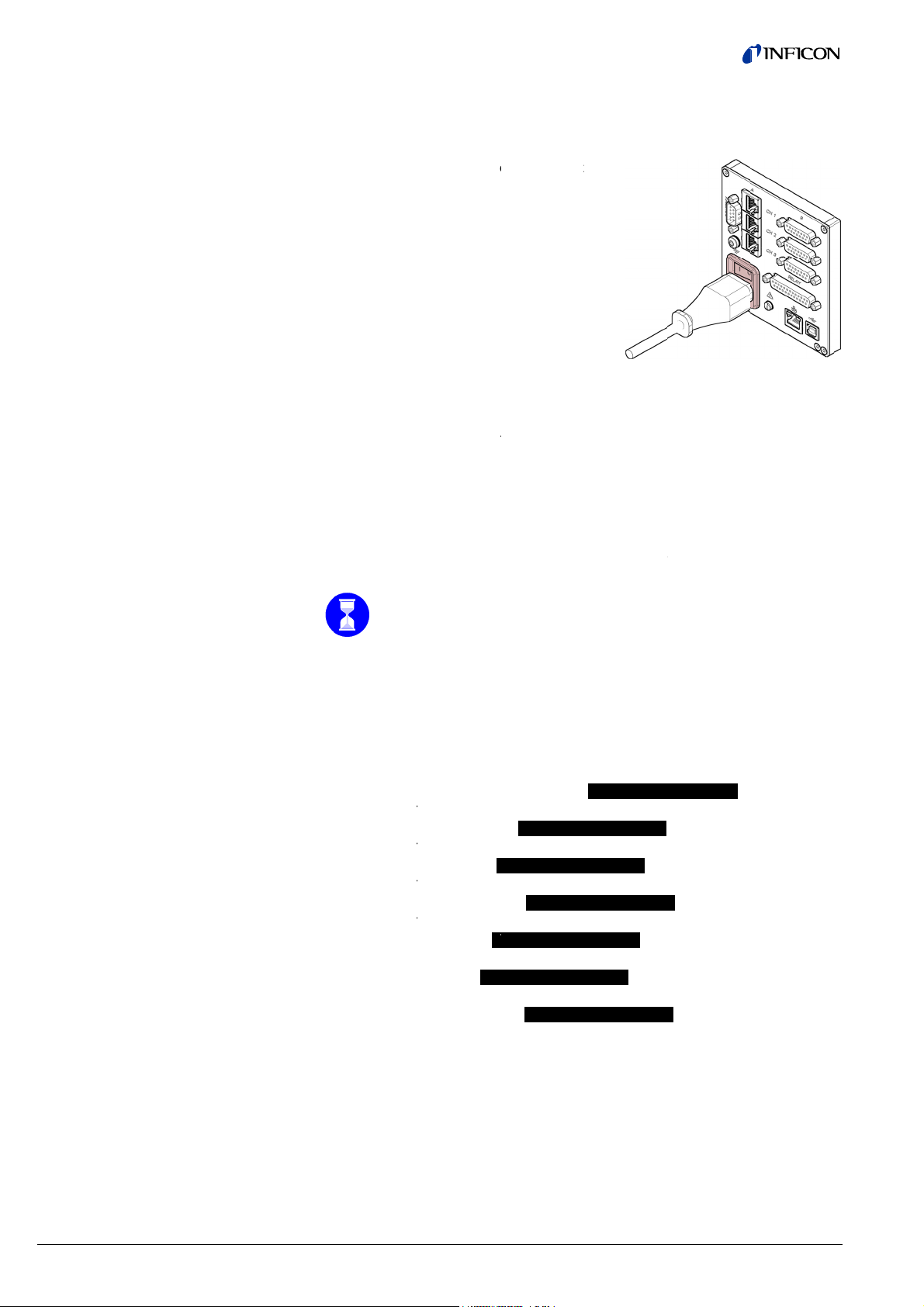
3.7 I
U
U
C
C
r
r
T
V
U
Tfr
w
U
c
u
t
p
o
g
c
o
f
i
d
t
c
e
k
o
t
o
o
B
r
c
a
r
c
a
k
o
nterface
SB Type
onnecto
B
he USB Type
GC50x via a
Con
the
B interface c
omputer (e.
nect the USB
nit using a s
nnector facil
. firmware up
interface con
reened (elec
tates direct c
ate, parame
ector to the
romagnetic c
mmunication
er saving (re
connecto
mpatibility)
with the
d/write)).
on the rear o
able.
f
3.8 I
nterface
SB Type
onnecto
A
SB Type B
he USB Type
ont of the uni
are update,
SB Type A
Con
unit.
A interface c
and is used
arameter sav
nect the USB
nnector with
or the conne
ng (read/writ
memory stic
master functi
tion of a US
), data logge
to the conne
nality is situ
memory stic
).
ctor on th
ted on the
(e.g. firm-
front of the
24
tina96e1-b (2016-12)
VGC501_VGC502_VGC503.
m
Page 25

C
3.9 Inte
e
e
o
n
h
e
t
o
s
h
e
r
c
a
t
a
e
n
c
s
e
V
a
m
c
e
n
Eth
rface Co
rnet
nector
The Et
puter.
ernet interfac
e allows dire
t communicat
ion with the
GC50x via a
om-
Gre
Yell
n LED
w LED
Ethern
Link or
Status
LED fla
Connect t
t
ransmit LED.
r packet det
hes or flicke
e Ethernet c
Indicates tha
ct LED. Indic
s, data are b
ble to the co
a hardware
tes the statu
ing transmitt
nector on
onnection h
the rear of th
s been establ
of the trans
d.
ission. Whe
unit.
ished.
this
tina96e1-b (2016-12) VG
501_VGC502_VGC503.om
25
Page 26

O
F
D
n
e
C
a
S
m
a
9
2
e
e
e
V
0
e
m
m
t
u
o
4
4.1
peratio
ront pan
l
Display
USB
connector
VGC502
VGC501
Operator k
GC5
ys
3
isplay VG
501
et points, par
St
tus measure
meter mode,
keylock
ent channel
.68×102 corr
.34×10-1 corr
Paramete
sponds to
sponds to
Display
Operator k
USB
connecto
r or bar graph
ys
r
Pressure
Measure
Measure
floating po
nential sta
nit
ent channel:
ent value in
int or expo-
us
26
tina96e1-b (2016-12)
VGC501_VGC502_VGC503.
m
Page 27
C
Displa
y
m
o
u
y
V
a
e
n
a
n
a
a
s
n
e
n
n
n
0
0
e
p
p
r
n
R
(
d
d
d
o
e
a
e
y
v
o
r
e
e
v
eMe
anenPreMe
e
anen
c
o
eMe
a
o
a
e
a
e
a
e
VGC502,
Mea
Set poi
Status me
Status me
Status me
GC503
urement cha
ts, parameter
surement cha
surement cha
surement cha
nel 1
mode,
ylock
k
nel 1
nel 2
nel 3
9.68×1
02 correspon
P
rameter or ba
s to
graph
ssure unit
M
asurement ch
asurement val
flo
ting point or
nnel 1:
ue in
xpo-
tial status
asurement ch
M
asurement val
flo
ting point or
nnel 1:
ue in
xpo-
tial status
M
asurement ch
asurement va
flo
ting point or
ne
ntial status
nnel 3:
lue in
xpo-
Para
Set p
keyloc
eter, bar gr
ints, param
k
ph
ter mode,
2.34×1
5.17×1
Param
Bar gra
Bar gra
Pressu
Set poi
-1
correspon
-6
correspon
ter
h
h with set p
e vs. time, tr
ts 1 … 6
s to
s to
int
nd
Param
ter mode acti
ated
elay on
Relay off
Keylock
n
Meas
specifi
rement cha
cally
nel
Measu
VG
rement chann
C502/503 onl
Degas acti
Err
Calib
l
ration factor a
Offs
t active
tive
e
High
vacuum sens
r active
tina96e1-b (2016-12) VG
501_VGC502_VGC503.om
27
Page 28
4.2
T
a
T
T
O
h
V
V
x
T
T(o
A
T
T
t
5
a
c
e
e
t
p
5
t
e
w
m
p
c
g
n
n
t
e
e
p
a
s
g
t
m
r
e
e
r
a
u
a
S
a
o
a
T
s
DAT
o
t
h
t
d
h
a
g
t
s
→
p
d
SENSOR
CON
o
RAL
→
LOGGER
SETUP
h
e
x
ETPOINT
>
→
>
e
→
>
>
o
u
e
o
)
o
urning t
nd Off
urning the
e VGC50
GC50x on
On
he power swi
urn the VGC
r centrally, vi
if
the unit is in
ch is on the r
0x on with th
a a switched
orporated in
ar of the uni
power switc
ower distribu
rack).
.
tor,
4.3
urning the
perating
GC50x off
Modes
fter power on
automaticall
•
identifies th
•
•
activates th
•
switches to
•
adapts the
connected).
urn the VGC
d
istributor, if th
Wai
corr
he VGC50x
•
Measureme
for displayin
•
Parameter
for displayin
− Switchin
for enter
− Gauge
for enter
− Gauge
for enter
− General
for enter
− Test pro
for runni
− Data log
for loggi
− Parame
for savin
, the VGC50x
y performs a
connected
parameters
he Measure
arameters if
0x off with th
e unit is incor
at least 10 s
ctly initialize
orks in the fo
nt mode
g measurem
ode
g and editing
g function pa
ing and displ
arameter gro
ing and displ
ontrol group
ing and displ
parameter gr
ing and displ
gram group
ng internal te
ger mode
g measurem
er transfer m
g (read/write)
…
elf-test
auges
hat were in e
ent mode
equired (if a
power switc
orated in a r
before turnin
itself.
llowing opera
nt values or
parameters (
ameter grou
ying threshol
p
ying gauge p
-
ying gauge c
up
GENE
ying general
t programs (
A
ent data (→
de
parameters (
fect before t
ifferent gaug
(or centrally
ck).
the VGC50
ing modes:
tatuses (→
33)
S
s (→ 34)
rameters (
ntrol param
arameters (
58)
>
61)
63)
e last power
was previo
, via a switch
on again in
31)
>
38)
ters (→ 46
50)
ff
sly
d power
rder for it to
28
tina96e1-b (2016-12)
VGC501_VGC502_VGC503.
m
Page 29

C
VGC5
0
Ba
FSR
1
rgraph
tina96e1-b (2016-12) VG
501_VGC502_VGC503.om
29
Page 30
V
GC502, VGC503
B
p
FSR
o
argra
30
tina96e1-b (2016-12) VGC501_VGC502_VGC503.
m
Page 31

C
4.4 Mea
s
A
g
e
5
h
M
h
e
y
s
e
a
e
u
e
n
n
d
d
t
p
n
n
d
d
q
a
T
ali
b
HAND
w
n
r
h
s
o
m
w
n
r
d
s
p
n
e
a
a
e
s
F
e
a
EMISS
o
a
e
i
n
e
e
i
c
o
t
n
h
l
M
H
n
d
y
d
HAND
s
M
0
h
n
o
h
a
G
n
e
h
e
e
d
m
e
m
y
o
m
s
s
n
h
t
v
n
i
w
n
n
djust
Chan
chann
(VGC
Turnin
urement
ing bar grap
ing measur
l
02/503 onl
g the gauge
ode
ment
)
on/off
Measur
• a b
• a m
• stat
If requir
Certain
set to
S
Availabl
Pira
Pira
Col
Col
Hot
Cap
Hot
ment mode i
r graph (if re
asurement v
s messages
ed a bar grap
gauges can
-ON
e for the follo
ni
ni / Capacita
cathode
cathode / Pi
ionization / Pi
acitance
ionization / Pi
s the standar
uired)
lue for each
for each mea
h may be dis
he unit alter
nd three. Th
ghts up.
e turned on
ing gauges:
ce
ani
rani
rani / Capacit
Press k
Gauge
word O
operating m
measuremen
urement cha
layed (→ 5
ates between
number of t
nd off manua
(→
48).
nce
y for >1 s:
witches off. I
F is displaye
ode of the V
nnel
5).
measureme
e selected m
lly, provided t
(PSG)
(PCG)
(PEG,
MAG)
(MPG)
(BPG,
HPG)
(CDG)
(BCG)
channel
stead of a m
.
C50x with di
t channels o
asurement c
e gauge con
asurement
play of
e, two
annel
rol is
alue the
Switc
ing the emi
sion on / off
For cer
sensor
Availabl
Pira
Pira
Col
Col
Hot
Cap
Hot
ain gauges t
arameter is
Switching
2.4×10⁻²
e for the follo
ni
ni / Capacita
cathode
cathode / Pi
ionization / Pi
acitance
ionization / Pi
Press k
Gauges
a status
e emission c
et to
n the emissi
bar.
ing gauges:
ce
ani
rani
rani / Capacit
Press k
The em
the Pira
measur
sensor.
Press k
The em
the hot
solid.
y for >1 s:
switches on.
message ma
n be switche
n is only pos
(PSG)
(PCG)
(PEG,
(MPG)
(BPG4
(CDG)
nce
(BCG)
y for >1 s:
ssion is switc
i or CDG se
ment value
y for >1 s:
ssion is switc
athode ioniz
Instead of th
y be displaye
on and off
(→ 45).
sible if the pr
MAG)
2 only)
hed off. The
sor is displa
f the hot cath
hed on. The
tion sensor i
measureme
.
anually, prov
ssure is belo
easurement
ed instead of
de ionizatio
easurement
displayed a
t value
ded the
value of
the
value of
d lid
tina96e1-b (2016-12) VG
501_VGC502_VGC503.om
31
Page 32

M
DidCm
easureme
n
h
g
0
0
2
/
0
a
0
a
n
n
0
5
0
u
e
t
f
n
P
e
C
e
G
n
G
n
p
c
c
3
C
d
b
e
e
f
t
P
a
g
l
G
0
a
n
n
e
othdi
P
PPM
B
B
H
B
C
CCn
n
C
u
r
g
MAG
100
Vx
10
v
n
e
m
e
S
m
e
3
o
t range
isplaying t
entification
hanging to
ode
e gauge
Pirani
(PSG40
PSG50
PSG55
Pirani
(PCG40
Cold c
(PEG10
Cold c
(MPG40
Hot io
Hot io
(BCG45
Linear
(CDG02
CDG04
Linear
(CDG02
CDG10
No ga
Gaug
the Parame
auge
, PSG400-S, PS
-S, PSG502-S, P
, PSG554)
Capacitanc
, PCG400-S, P
thode gaug
, MAG500, MA
thode / Pira
0, MPG401, MP
ization / Pira
ization / Ca
)
gauge (capa
0D, CDG025, CD
Dhs, CDG100, C
gauge (capa
5D, CDG025D-X
D, CDG100D2,
ge connecte
connected,
er
I
the unit is op
dicated.
i
ossible caus
•
negative dr
•
activated o
Firs
100-S, PSG101
G510-S, PSG51
gauge
G550, PCG552,
504)
i gauge
500, MPG504)
i gauge
acitance / Pir
itance, analo
G045,CDG045-H
DG100Dhs)
itance, digita
, CDG045D, CD
DG160D, CDG2
ut not identifi
erated with li
s:
ift
fset correctio
, select the r
P
-S, PSG500,
2-S, PSG550,
CG554)
(BPG400)
(BPG402)
(HPG400)
ani gauge
g)
,
)
045D2,
0D)
ble
→
ear gauges (
.
quired meas
ress keys for
F
r the measu
e connected
splayed for 6
xxx
xxx
/
xxx
DGxxx
DGxxxD
xxxD
oSENSOR
oIDENT.
33
DG), negati
rement chan
0.5 … 1 s:
ement chann
auge is auto
s:
xxx
.xx
MBAR
MBAR
I
I
I
I
I
I
I
I
I
V
F
I
I
e pressures
el with k
l in question
matically iden
rsion during
R during 3 s
ay be
y.
the type of
tified and
s, then
32
tina96e1-b (2016-12)
VGC501_VGC502_VGC503.
m
Page 33

C
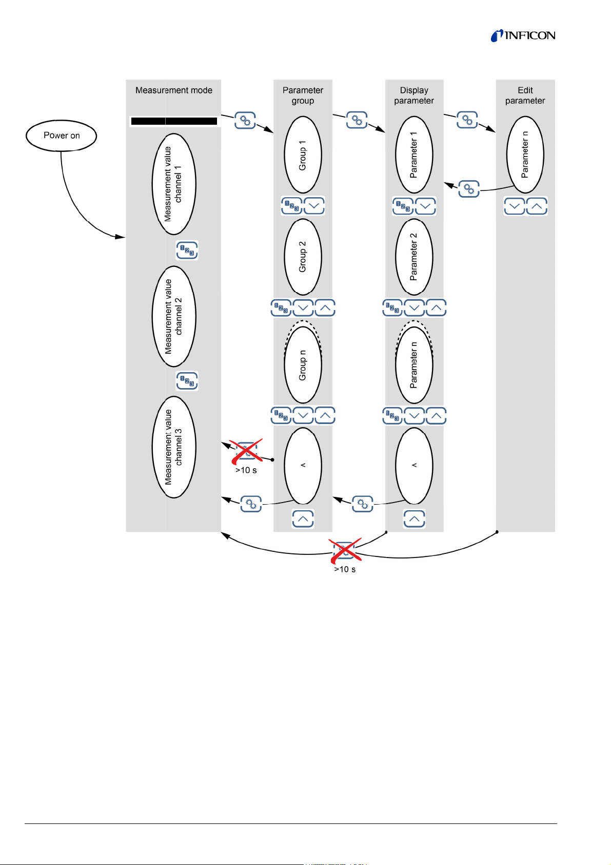
4.5 Para
m
n
g
a
d
e
r
a
o
e
t
u
t
a
s
e
e
n
o
e
u
h
i
n
u
t
b
c
g
g
e
a
a
T
u
n
e
r
n
s
e
→
6
e
h
o
a
→
Select
eter Mo
ing a param
e
ter group
The Pa
as well
operati
ameter mod
s for testing
n the individ
is used for di
he VGC50x
al parameter
Unit switch
meter mod
displayed i
Select
group
splaying, edit
nd for saving
are divided i
s from meas
. The respec
place of the
Swit
Gau
Gau
Gen
Test
Dat
Par
ing and enteri
measureme
nto groups.
rement mod
ive paramete
bar graph.
hing functio
e parameter
e control →
ral paramet
parameters
logger →
meter transf
ng parameter
t data. For e
to para group is
parameters
→ 38
46
rs → 50
58
1
r → 63
values
se of
34
Readi
param
Editin
in a p
g a parame
eter group
and saving
rameter gro
ter in a
a paramete
up
Confirm gr
up
Confirm th
parameter.
he value flas
es and can n
ow be
edited.
Edit the val
e.
Save the c
ange and ret
rn to read m
de.
tina96e1-b (2016-12) VG
501_VGC502_VGC503.om
33
Page 34

4.5.1 Switching Function
Parameters
Parameters in this group
SETPOINT >I The switching function parameter group is used for
displaying, editing and entering threshold values and
assigning the two (VGC501), four (VGC502) or six
(VGC503) switching functions to a measurement
channel.
SP1-CH I Configuration of switching function 1
SP1-L I Switching function 1 lower threshold
SP1-H I Switching function 1 upper threshold
SP2-CH I Configuration of switching function 2
SP2-L I Switching function 2 lower threshold
SP2-H I Switching function 2 upper threshold
SP3-CH I Configuration of switching function 3
(VGC502/503 only)
SP3-L I Switching function 3 lower threshold
(VGC502/503 only)
SP3-H I Switching function 3 upper threshold
(VGC502/503 only)
SP4-CH I Configuration of switching function 4
(VGC502/503 only)
SP4-L I Switching function 4 lower threshold
(VGC502/503 only)
SP4-H I Switching function 4 upper threshold
(VGC502/503 only)
SP5-CH I Configuration of switching function 5
(VGC503 only)
SP5-L I Switching function 5 lower threshold
(VGC503 only)
SP5-H I Switching function 5 upper threshold
(VGC503 only)
SP6-CH I Configuration of switching function 6
(VGC503 only)
SP6-L I Switching function 6 lower threshold
(VGC503 only)
SP6-H I Switching function 6 upper threshold
(VGC503 only)
< I One level back
The VGC501 has two, the VGC502 has four and the VGC503 has six, switching
functions with two adjustable thresholds each. The status of the switching functions
is displayed on the front panel and can be evaluated via the floating contacts at the
CONTROL, respectively RELAY connector.
• VGC501: CONTROL connector (→ 21)
• VGC502, VGC503: RELAY connector (→ 22)
34 tina96e1-b (2016-12) VGC501_VGC502_VGC503.om
Page 35

C
c
n
m
m
n
m
e
m
t
SP1
h
p
e
u
e
u
e
t
½
d
DISAB
r
e
d
d
e
w
e
e
b
c
d
a
w
.
Sele
Editi
para
ting a para
g and savi
eter
eter
g the
The na
e.g.:
Select
parame
e of the para
er value are
-CH
Switc
ing function 1 tu
arameter. Th
meter and th
isplayed.
I
ned off
value flash
currently val
s and can no
id
be
edited.
Press k
The val
Press k
The val
Save th
y for <1 s:
e is increase
y for >1 s:
e is increase
change and
d/decreased
d/decreased
return to rea
y 1 incremen
ontinuously.
mode.
t.
tina96e1-b (2016-12) VG
501_VGC502_VGC503.om
We recom
or the low
end setting
r threshold
he upper thr
decade belo
shold ½ dec
the upper, t
de above the
hreshold limit
lower,
35
Page 36

Configuring a switching
function
Limits of the lower switching
thresholds
SP1-CH I Configuring a switching function.
SP1-CH 1 I Switching function 1 is assigned to
Value
channel 1
SP1-CH 2 I Switching function 1 is assigned to
channel 2
(VGC502/503 only)
SP1-CH 3 I Switching function 1 is assigned to
channel 3
(VGC503 only)
SP1-CH DISABLED I Switching function 1 is factory-deactivated
SP1-CH ENABLED I Switching function 1 is always turned on
The lower and the upper threshold of a switching function are always
assigned to the same channel. The last assignment is valid for both
thresholds.
SP1-L I The lower threshold (Setpoint low) defines the
Value
pressure at which the switching function is
activated when the pressure is dropping.
e.g.: SP1-L 5.00-4 I gauge dependent.
If another gauge type is connected, the
VGC50x automatically adjusts the switching
threshold if required.
PSGxxx I
PCGxxx I
PEG100/MAGxxx I
MPGxxx I
BPG400 I
BPG402 I
HPG400 I
BCG450 I
CDGxxx I
CDGxxxD I
SPx-L min. SPx-L max.
-3 *)
1×10
1×10
1×10
1×10
1×10
1×10
-3 *)
-9
-9
-8
-8
-6
-8
= SPx-H max.
2×10
2×10
F.S. / 1000
F.S. / 1000
all values in mbar, GAS=nitrogen
*)
2×10⁻⁴ mbar if RNG-EXT (Pirani range extension) is activated (→ 51)
The minimum hysteresis between the upper and lower switching
threshold amounts to at least 10% of the lower threshold (logarithmic
gauges) or 1% of the full scale value (linear gauges). The upper
threshold is if necessary automatically adjusted to a minimum
hysteresis. This prevents unstable states.
36 tina96e1-b (2016-12) VGC501_VGC502_VGC503.om
Page 37

Limits of the upper switching
thresholds
SP1-H I The upper switching threshold (Setpoint high)
Value
defines the pressure at which the switching
function is deactivated when the pressure is
rising.
e.g.: SP1-H 1500 I gauge dependent.
If another gauge type is connected, the
VGC50x automatically adjusts the threshold
if required.
PSGxxx I
PCGxxx I
PEG100/MAGxxx I
MPGxxx I
BPG400 I
BPG402 I
HPG400 I
BCG450 I
CDGxxx I
CDGxxxD I
SPx-H min. SPx-H max.
3
1×10
1.5×10
-2
1×10
3
1×10
3
1×10
= SPx-L min.
1×10
1×10
3
3
1.5×10
F.S.
F.S.
3
3
all values in mbar, GAS=nitrogen
The minimum hysteresis between the upper and lower switching
threshold amounts to at least 10% of the lower threshold (logarithmic
gauges) or 1% of the full scale value (linear gauges). This prevents
unstable states.
tina96e1-b (2016-12) VGC501_VGC502_VGC503.om 37
Page 38

4.5.2 Gauge parameters
Parameters in this group
SENSOR >I The sensor parameter group is used for displaying,
entering and editing parameters of the connected
gauges.
DEGAS I Cleaning the electrode system.
FSR I Measurement range linear gauges.
FILTER I Measurement value filter.
OFFSET I Offset correction.
GAS I Correction factor for other gases.
COR I Offset correction.
HV-CTRL I Activating / deactivating high vacuum measurement
circuit.
EMISSION I Emission.
FILAMENT I Filament selection.
DIGITS I Display resolution.
< I One level back.
Some parameters are not available for all gauges and thus not always displayed.
39 40 41 42 44 44
→
45 45 45
46
PSGxxx I
PCGxxx I
PEG100/MAGxxx I
MPGxxx I
BPG400 I
BPG402 I
Available for
HPG400 I
BCG450 I
CDGxxx I
CDGxxxD I
DEGAS I
− −
− −
− −
− −
−
−
− −
−
−
−
FSR I
FILTER I
OFFSET I
GAS I
COR I
HV-CTRL I
EMISSION I
FILAMENT I
DIGITS I
− − −
− − −
− −
− − −
− − −
−
− − −
−
− − −
− − −
−
−
−
−
−
−
−
−
−
−
−
38 tina96e1-b (2016-12) VGC501_VGC502_VGC503.om
Page 39

C
Deg
a
n
m
n
m
t
c
n
n
d
d
DEGAS
s
.
s
w
/
n
r
/
OFF
c
a
k
a
e
e
h
g
s
M
p
h
m
n
s
u
d
a
7
o
a
o
e
.
s
)
o
y
n
r
i
s
s
Conta
instabili
the ele
ination depo
ies of the me
trode system
its on the ele
asurement v
trode system
lues. The de
of hot catho
as function f
e gauges ma
cilitates clea
cause
ing of
Editi
para
g and savi
eter
g a
Availabl
Pira
Pira
Col
Col
Hot
Hot
Cap
Hot
The dega
BPG402 g
e for the follo
ni
Capacita
ni
cathode
cathode / Pi
ionization / Pi
ionization
Pi
acitance
ionization / Pi
DEGAS
DEGAS ON
process wor
auges: The D
ing gauges:
ce
ani
rani
rani
rani / Capacit
I
I
I
Start D
180 sec
s only at pre
gas function
(PSG)
(PCG)
(PEG,
(MPG)
(BPG)
(HPG)
(CDG)
nce
(BCG)
Value
Normal o
Degas: T
heated to
bombard
system is
180 s.
gas. Duratio
nds (may al
sures below
acts only up
MAG)
eration (Deg
e electron c
≈700 °C by e
ent and the
thus cleaned
of the Dega
o be aborted
.2×10-6 mba
n the active f
s blocked)
llection grid i
lectron
lectrode
Duration =
function
.
.
lament.
Abort D
Save c
gas.
ange and ret
rn to read m
de.
tina96e1-b (2016-12) VG
501_VGC502_VGC503.om
39
Page 40

Measuring range (F.S.) of
linear gauges
For linear analog gauges, the full scale (F.S.) value has to be defined on the basis
of the connected gauge type. For linear digital gauges and logarithmic gauges it is
automatically recognized.
Available for the following gauges:
Pirani
(PSG)
Pirani / Capacitance (PCG)
Cold cathode
Cold cathode / Pirani
Hot ionization / Pirani
Capacitance
Hot ionization / Pirani / Capacitance
FSR I
Value
(PEG, MAG)
(MPG)
(BPG, HPG)
(CDG)
(BCG)
e.g. FSR 1000 MBAR I 0.01 mbar, 0.02 mbar, 0.05 mbar
0.01 Torr, 0.02 Torr, 0.05 Torr
0.10 mbar, 0.25 mbar, 0.50 mbar
0.10 Torr, 0.25 Torr, 0.50 Torr
1 mbar, 2 mbar, 5 mbar
1 Torr, 2 Torr, 5 Torr
10 mbar, 20 mbar, 50 mbar
10 Torr, 20 Torr, 50 Torr
100 mbar, 200 mbar, 500 mbar
100 Torr, 200 Torr, 500 Torr
1000 mbar, 1100 mbar
1000 Torr
2 bar, 5 bar, 10 bar, 50 bar
A conversion table can be found in the
Appendix (→ 102).
40 tina96e1-b (2016-12) VGC501_VGC502_VGC503.om
Page 41

Measurement value filter
The measurement value filter permits a better evaluation of unstable or disturbed
measuring signals.
The measurement value filter does not affect the analog output
(→ 22).
FILTER I
FILTER OFF I No measurement value filter
FILTER FAST I Fast:
Value
The VGC50x responds quickly to fluctuations in the measurement value. As a result,
it will respond faster to interference in the
measured values.
Pressure p
FILTER NORMAL I Normal (factory setting):
FILTER SLOW I Slow:
Time t
Good relationship between response and
sensitivity of the display and the switching
function to changes in the measured values.
Pressure p
Time t
The VGC50x does not respond to small
changes in measured values. As a result, it
will respond more slowly to changes in the
measured values.
Pressure p
Time t
tina96e1-b (2016-12) VGC501_VGC502_VGC503.om 41
Page 42

Offset corr
e
Tva
A
T
O
W
p
d
d
o
o
e
e
e
o
OFFSE
OFFSE
o
e
d
a
/ C
:
v
e
OFF
a
R
t
T
e
w
c
s
s
hmen
e
e
e
a
e
t
o
n
d
s
e
u
i
m
s
r
m
e
o
.
controller
ction of the
he offset valu
lue.
vailable for th
Pirani
Pirani / Ca
Cold catho
Cold catho
Hot ionizati
Capacitanc
Hot ionizati
he offset corr
the display
the display
the analog
e is displaye
e following g
acitance
e
e / Pirani
on / Pirani
e
on / Pirani
ction affects
d measurem
d threshold
outputs at th
I
and readjust
uges:
apacitance
nt value
alue of the s
CONTROL
Wert
I Off
d according
(PSG)
(PCG)
(PEG, MAG)
(MPG)
(BPG, HPG)
(CDG)
(BCG)
itching functi
onnector (→
et correction
o the actual
ns
21, 22)
factory-deact
easurement
ivated
e.g.
hen offset c
a
tual measur
9.53
P
S
rrection is ac
ment value.
I Off
ress key for >
e offset valu
T
v
lue is accept
eset the offs
ave change a
ivated, the s
his allows m
et correction
in t
e relevant u
t)
1.5 s:
is readjuste
d as new off
t value.
nd return to r
ved offset val
asuring relat
activated (di
its of measu
(the actual
et value).
ad mode.
ue is subtract
ive to a refer
play
e-
easurement
d from the
nce pressure
42
tina96e1-b (2016-12)
VGC501_VGC502_VGC503.
m
Page 43

C
Zero
G
n
n
d
d
OFFSE
t
w
/
n
r
z
d
OF
s
g
t
n
a
a
j
y
o
M
H
s
s
e
v
s
e
v
s
a
m
p
h
m
adjustment of a digital
CD
Availabl
Pira
Pira
Col
Col
Hot
Cap
Hot
First adjus
e for the follo
ni
ni
Capacita
cathode
cathode / Pi
ionization / Pi
acitance
ionization / Pi
the gauge a
ing gauges:
ce
ani
rani
rani / Capacit
d then the c
(PSG)
(PCG)
(PEG,
(MPG)
(BPG,
(CDG)
nce
(BCG)
ntroller.
MAG)
HPG)
When the
deactivate
ero of the g
.
uge is readju
ted, the offs
t correction
ust be
e.g.
OFFSET
I
Value
I
Zero adju
tment deacti
Lit
as long as
ated
olid after >1.
key remains
5 s and
ressed
Press >
Zero ad
.5 s:
ustment of th
e digital CDG
.
After adju
measuring
several di
ting the zero
resolution of
its are displa
oint, a zero
the CDG (noi
ed.
alue is displ
e, drift), a ze
yed. Due to t
ro with plus/
e
inus
tina96e1-b (2016-12) VG
501_VGC502_VGC503.om
43
Page 44

Correction factor GAS
The correction factor GAS allows
• the measured value to be calibrated for the preset gases N
, Ar, H2, He, Ne, Kr
2
and Xe, or
• manual input of the correction factor for other gases (COR).
→ Characteristic curves in [1] … [16].
This parameter is not available for the unit of measurement: Volt.
Available for the following gauges:
Pirani
(PSG) <1 mbar
Only for pressures
Pirani / Capacitance (PCG) <1 mbar
Cold cathode
Cold cathode / Pirani
Hot ionization / Pirani
(PEG, MAG)
(MPG) <1×10⁻³ mbar
(BPG) <1×10⁻³ mbar
Hot ionization / Pirani (HPG)
Capacitance (CDG)
Hot ionization / Pirani / Capacitance
GAS I
GAS N2 I Gas: nitrogen / air (factory setting)
GAS AR I Gas: argon
Value
(BCG) <1×10⁻³ mbar
Calibration factor COR
GAS H2 I Gas: hydrogen
GAS HE I Gas: helium
GAS NE I Gas: neon
GAS KR I Gas: krypton
GAS XE I Gas: xenon
GAS COR I Calibration factor for other gases by
manually entering parameter COR
The calibration factor COR allows the measured value to be calibrated for other
gases (→ characteristic curve in [1] … [16]). This parameter is effective in the
entire measurement range of the gauge.
Precondition: Parameter "GAS COR" is set (except capacitance gauges).
This parameter is not available with the measurement unit: Volt.
Available for the following gauges:
Pirani
(PSG)
Pirani / Capacitance (PCG)
Cold cathode
Cold cathode / Pirani
Hot ionization / Pirani
(PEG, MAG)
(MPG)
(BPG, HPG)
Capacitance (CDG)
Hot ionization / Pirani / Capacitance
Value
(BCG)
COR I
e.g. COR 1.00 I No correction
e.g. COR 1.53 I Measurement value corrected by a
factor of 0.10 … 10.00
44 tina96e1-b (2016-12) VGC501_VGC502_VGC503.om
Page 45

Turning the gauge on / off
Emission
Activating / deactivating the high vacuum measurement circuit (→ also [31]).
Available for the following gauges:
Pirani
(PSG)
Pirani / Capacitance (PCG)
Cold cathode
Cold cathode / Pirani
Hot ionization / Pirani
(PEG, MAG)
(MPG)
(BPG, HPG)
Capacitance (CDG)
Hot ionization / Pirani / Capacitance
HV-CTRL I
HV-CTRL ON I High vacuum measurement circuit
Value
(BCG)
activated
HV-CTRL OFF I High vacuum measurement circuit
deactivated
Switching the emission on and off.
Available for the following gauges:
Pirani
(PSG)
Pirani / Capacitance (PCG)
Cold cathode
Cold cathode / Pirani
Hot ionization / Pirani
(PEG, MAG)
(MPG)
(BPG402 only)
Capacitance (CDG)
Hot ionization / Pirani / Capacitance
Value
(BCG)
Filament
EMISSION I
EMISSION AUTO I The emission is switched on and off
automatically by the gauge
EMISSION HAND I The emission is switched on and off
by the user
The symbol lid solid, if the emission is switched on.
Means of selection.
Available for the following gauges:
Pirani
(PSG)
Pirani / Capacitance (PCG)
Cold cathode
Cold cathode / Pirani
Hot ionization / Pirani
(PEG, MAG)
(MPG)
(BPG402 only)
Capacitance (CDG)
Hot ionization / Pirani / Capacitance
FILAMENT I
FILAMENT AUTO I The gauge automatically alternates
Value
(BCG)
between the filaments
FILAMENT FIL 1 I Filament 1 active
FILAMENT FIL 2 I Filament 2 active
tina96e1-b (2016-12) VGC501_VGC502_VGC503.om 45
Page 46

Display resolution
4.5.3 Gauge Control
Display resolution of measured values.
Available for the following gauges:
Pirani
(PSG)
Pirani / Capacitance (PCG)
Cold cathode
Cold cathode / Pirani
Hot ionization / Pirani
(PEG, MAG)
(MPG)
(BPG, HPG)
Capacitance (CDG)
Hot ionization / Pirani / Capacitance
Value
DIGITS I
DIGITS AUTO I Automatic
DIGITS 1 I e.g. 2E-1 or 500
DIGITS 2 I e.g. 2.5E-1 or 520
DIGITS 3 I e.g. 2.47E-1 or 523
DIGITS 4 I e.g. 2.473E-1 or 523.7
*)
The mantissa is dependent on the connected gauge and the currently valid
(BCG)
*)
(factory setting)
pressure value.
With PSG and PCG gauges in the pressure range p<1.0E-4 mbar and activated
RNG-EXT (→ 51) the display is reduced by one decimal digit.
SENSOR-CONTROL >I The sensor control group is used for displaying,
entering and editing parameters which define how the
connected gauges are activated/deactivated.
Parameters in this group
This group is available for the PEG/MAG gauges only.
S-ON I Gauge activation
S-OFF I Gauge deactivation
T-ON I ON threshold (VGC502/503 only)
T-OFF I OFF threshold
< I One level back
46 tina96e1-b (2016-12) VGC501_VGC502_VGC503.om
Page 47

Gauge activation
ON threshold
(VGC502, VGC503 only)
Certain gauges can be activated by different means.
S-ON I
S-ON HAND I Manual activation:
Value
The gauge is activated by pressing the
key.
S-ON HOTSTART I Hot start:
The gauge is automatically activated when
the VGC50x is turned on. Measurement is
thus automatically resumed after a power
failure. Gauge deactivation → 48.
S-ON CH 1 I
(VGC502/503 only)
By channel 1:
The subsequent parameter T-ON is used to
specify the switch-on threshold. The sensor
is switched on when the pressure on channel 1 falls below the switch-on threshold.
S-ON CH 2 I
(VGC502/503 only)
By channel 2:
The subsequent parameter T-ON is used to
specify the switch-on threshold. The sensor
is switched on when the pressure on channel 2 falls below the switch-on threshold.
S-ON CH 3 I
(VGC503 only)
By channel 3:
The subsequent parameter T-ON is used to
specify the switch-on threshold. The sensor
is switched on when the pressure on channel 3 falls below the switch-on threshold.
Definition of the ON threshold for the gauge to be activated by a gauge connected
to the other measurement channel.
This parameter is only available if the sensor activation parameter is set to
S-ON CH 1, CH 2 or CH 3 (VGC503 only).
Value
T-ON I
e.g.: T-ON 100 I The sensor is switched on when the pres-
sure on the respective channel falls below
the switch-on threshold.
Value T-OFF must be ≥ T-ON .
tina96e1-b (2016-12) VGC501_VGC502_VGC503.om 47
Page 48

Gauge deactivation
OFF threshold VGC501
Certain gauges can be deactivated by different means.
S-OFF I
S-OFF HAND I Manual deactivation:
Value
The gauge is deactivated by pressing the
key
S-OFF SELF I Self control:
The subsequent parameter T-OFF is used
to specify the switch-off threshold. The sensor is switched off when the pressure at the
sensor exceeds the switch-off threshold.
S-OFF CH 1 I
(VGC502/503 only)
By channel 1:
The subsequent parameter T-OFF is used
to specify the switch-off threshold. The sensor is switched off when the pressure on
channel 1 exceeds the switch-off threshold.
S-OFF CH 2 I
(VGC502/503 only)
By channel 2:
The subsequent parameter T-OFF is used
to specify the switch-off threshold. The sensor is switched off when the pressure on
channel 2 exceeds the switch-off threshold
S-OFF CH 3 I
(VGC503 only)
By channel 3:
The subsequent parameter T-OFF is used
to specify the switch-off threshold. The sensor is switched off when the pressure on
channel 3 exceeds the switch-off threshold.
Definition of the OFF threshold for the gauge to be deactivated by itself.
This parameter is only available if the sensor deactivation parameter is set to
S-OFF SELF.
Value
T-OFF I
e.g.: T-OFF 1.00-2 I The sensor is switched off when the pres-
sure exceeds the switch-off threshold.
48 tina96e1-b (2016-12) VGC501_VGC502_VGC503.om
Page 49

OFF threshold VGC502,
VGC503
Definition of the OFF threshold for the gauge to be deactivated by a gauge
connected to the other measurement channel or by itself.
This parameter is only available if the sensor deactivation parameter is set to
S-OFF CH 1, CH 2, CH 3 (VGC503 only) or S-OFF SELF.
T-OFF I
Value
e.g.: T-OFF 100 I The sensor is switched off when the pres-
sure on the respective channel exceeds the
switch-off threshold.
Value T-OFF must be ≥ T-ON .
tina96e1-b (2016-12) VGC501_VGC502_VGC503.om 49
Page 50

4.5.4 General Parameters
Parameters in this group
GENERAL >I The General parameters group is used for displaying,
entering and editing generally applicable system parameters.
UNIT I Measurement unit
BAUD USB I Transmission rate USB interface
RNG-EXT I Pirani range extension
AO-MODE I Recorder output
ERR-RELAY I Error relay
BARGRAPH I Bar graph display
BACKLIGHT I Backlight
SCREENSAVE I Screensaver
CONTRAST I Contrast adjustment
DEFAULT I Factory settings
LANGUAGE I Language
FORMAT I Number format, measurement value
Measurement unit
END VAL I Display of measurement range end value
< I One level back
Unit of measured values, thresholds etc. (conversion table → 102).
UNIT I
UNIT MBAR I mBar
UNIT HPASCAL I hPa (factory setting)
UNIT TORR I Torr (only available if Torr lock is not
Value
activated → 59)
UNIT PASCAL I Pa
UNIT MICRON I Micron (= 0.001 Torr) (only available if Torr
lock is not activated → 59)
UNIT VOLT I V
A change of the pressure unit influences also the pressure unit settings of the BPG,
HPG and BCG gauges.
VGC501 only: If the measurement unit micron is selected, automatic changeover to
Torr occurs above 99000 micron. Below 90 Torr automatic changeover back to the
measurement unit micron occurs.
50 tina96e1-b (2016-12) VGC501_VGC502_VGC503.om
Page 51

C
Tran
s
n
o
C
e
e
p
t
n
n
d
d
E
o
c
a
m
g
e
n
e
a
a
w
t
BAUD USB
BAUD USB
BAUD USB
BAUD USB
BAUD USB
o
i
a
c
a
w
n
r
D
E
s
e
a
r
h
r
i
t
l
t
f
9600
19200
38400
57600
115200
n
n
a
m
s
v
a
n
u
a
m
e
p
AO
s
d
u
u
u
a
b
/ me
M
H
e
x
o
r
h
o
t
t
r
t
g
b
n
c
t
h
a
t
c
e
t
r
t
a
t
r
c
h
w
l
i
u
s
o
a
u
s
h
mission rat
Transm
ission rate of
he USB inter
ace.
Value
Pira
i range ext
nsion
BAUD
The dis
affects
Availabl
Pira
Pira
Col
Col
Hot
Cap
Hot
lay and setp
he control un
Use the p
Capacitan
5×10⁻⁵ mb
e for the follo
ni
ni / Capacita
cathode
cathode / Pi
ionization / Pi
acitance
ionization / Pi
I
int adjustme
t).
rameter Pira
e gauges wit
r.
ing gauges:
ce
ani
rani
rani / Capacit
I
9600 bau
I
19200 ba
I
38400 ba
I
57600 ba
I
115200 b
t range can
i range exten
h display
nce
Value
(PSG)
(PCG)
(PEG,
(MPG)
(BPG,
(CDG)
(BCG)
d
d
d
ud (factory s
e extended (
sion only wit
asurement r
MAG)
HPG)
tting)
he setting on
Pirani and P
nge up to
y
rani /
Rec
(VG
rder output
502, VGC5
03)
RNG-
The rec
is a fun
the volt
Funda
curves:
• A lo
ord
the l
• A li
ord
volt
valu
The av
it is sho
voltage
The swi
RNG-EXT
RNG-EXT
order output i
tion of the pr
ge is called t
entally we h
arithmic cha
rs of magnitu
ogarithm of t
ear characte
rs of magnitu
ge is proport
e will result in
ilable charac
wn how to ca
U (in volts).
Assign the
• Select
• Select
• Select
tching functio
I
I
ABLED
I
a program
ssure on the
he characteri
ve to distingu
acteristic cur
de in the me
e pressure a
istic curve is
de in the me
onal to the pr
the maximu
eristic curves
culate the pr
recorder out
parameter
channel with
characteristic
ns can be as
Deactivat
Display e
able analog
sensor. The
tic curve of t
ish between l
e is useful if
surement. In
d then scale
seful if the p
surement. In
ssure value.
output volta
will be descri
ssure p (in m
ut to a certai
-MODE
key
curve with
igned to the
d (factory se
tended to 5×
utput. The re
elation betw
e output.
garithmic an
he pressure
his case it is
the result in
essure range
his case the
You can spe
e.
bed in the foll
bar) from the
channel wit
key
hannels any
ting)
-5
mbar
10
order output
en the press
linear chara
ange covers
appropriate t
suitable man
covers only
ecorder outp
ify which pre
owing. In eac
recorder outp
the key:
ay
voltage
re and
cteristic
everal
take
ner.
few
t
sure
case
ut
tina96e1-b (2016-12) VG
501_VGC502_VGC503.om
51
Page 52

AO-MODE I
AO-MODE LOG I Logarithmic representation of the entire
Value
measuring range (factory setting).
PSG: p = 10^[U/(10 / 7) - 4]
PCG: p = 10^[U/(10 / 7) - 4]
PEG/MAG: p = 10^[U/(10 / 7) - 9]
MPG: p = 10^[U/(10 / 12) - 9]
CDG: p = 10^[U/(10 / 4) - 4] × FS
BPG: p = 10^[U/(10 / 12) - 9]
BCG: p = 10^[U/(10 / 12) - 9]
HPG: p = 10^[U/(10 / 9) - 6]
AO-MODE LOG A I Logarithmic representation of the entire
measuring range (compatible to VGC012,
VGC023, VGC032).
PSG: p = 10^[U/(10/6) - 3]
PCG: p = 10^[U/(10/7) - 4]
PEG/MAG: p = 10^[U/(9/7) - 9 - 7/9]
MPG: p = 10^[U/(10/11) - 8]
CDG: p = 10^[U/(10/4) - 4] × FS
BPG400: p = 10^[(U - 7.75) / 0.75]
BPG402: p = 10^[U - 8]
BCG: p = 10^[(U - 7.75) / 0.75]
HPG: p = 10^[U/(10/9) - 6]
AO-MODE LOG -6 I Logarithmic representation of a part of the
measuring range (2.5 V/decade).
p = 10^[U/(10/4) - 10]
AO-MODE LOG -3 I Logarithmic representation of a part of the
measuring range (2.5 V/decade).
p = 10^[U/(10/4) - 7]
AO-MODE LOG +0 I Logarithmic representation of a part of the
measuring range (2.5 V/decade).
p = 10^[U/(10/4) - 4]
AO-MODE LOG +3 I Logarithmic representation of a part of the
measuring range (2.5 V/decade).
p = 10^[U/(10/4) - 1]
AO-MODE LOG C1 I Logarithmic representation matched to the
following sensor combination:
• PSG/PCG on channel 1
• PEG on channel 2
p = 10^[U/(10/12) - 9]
AO-MODE LOG C2 I Logarithmic representation matched to the
following sensor combination:
• CDG on channel 1
• CDG on channel 2
This characteristic curve is only useful if the
sensors have different measuring ranges.
The total measuring range of the sensor
combination is represented logarithmically
in the range 0…10 V.
52 tina96e1-b (2016-12) VGC501_VGC502_VGC503.om
Page 53

AO-MODE LOG C3 I Logarithmic representation matched to the
following sensor combination:
• CDG on channel 1
• CDG on channel 2
• CDG on channel 3
This characteristic curve is only useful if the
sensors have different measuring ranges.
The total measuring range of the sensor
combination is represented logarithmically
in the range 0…10 V.
The three sensors must be sor-
ted with regard to their measuring range (FS). The sort order
may be increasing or decreasing.
AO-MODE LIN -10 I Linear representation:
U = 10 V is equivalent of p = 10
-10
…
p = U/10 × 10
Adjustable in the range LIN -10 … LIN +3
-10
mbar
AO-MODE LIN +3 I Linear representation:
AO-MODE IM221 I Logarithmic representation of the IM221
AO-MODE LOG C4 I Logarithmic representation of 12 decades
AO-MODE PM411 I Nonlinear characteristic curve of the output
AO-MODE CH x I Output voltage = input voltage
AO-MODUS PRM10K I Nonlinear characteristic curve of the output
AO-MODUS IMR110 I Logarithmic representation compatible with
AO-MODUS IMR120 I Logarithmic representation compatible with
AO-MODUS IMR310 I Logarithmic representation compatible with
AO-MODUS IMR320 I Logarithmic representation compatible with
+3
U = 10 V is equivalent of p = 10
+3
p = U/10 × 10
mbar
controller (1 V/decade):
U = 8 V is equivalent of p = 10-2 mbar
p = 10^[U - 10]
(0.83 V/decade) matched the following sensor combination:
• PCG on channel 1
• BPG402 on channel 2
p = 10^[U/(10/12) - 9]
U = 10 V is equivalent of p = 1000 mbar.
The switching point between the sensors is
-2
mbar.
10
as with the PM411 board.
as with the PRM10K gauge from Edwards.
IMR110 gauge, p = 10^[U/2 - 6]
IMR120 gauge, p = 10^[U/2 - 8]
IMR310 gauge, p = 10^[U*6/10 - 6]
IMR320 gauge, p = 10^[U*7/10 - 9]
tina96e1-b (2016-12) VGC501_VGC502_VGC503.om 53
Page 54

Error relay
Switching behaviour of the error relay.
ERR-RELAY I
ERR-RELAY ALL I Switches for all errors (factory setting)
ERR-RELAY no SE I Only unit errors
ERR-RELAY CH 1 I Error sensor 1 and unit error
ERR-RELAY CH 2 I Error sensor 2 and unit error (VGC502/503
Value
only)
ERR-RELAY CH 3 I Error sensor 3 and unit error (VGC503 only)
54 tina96e1-b (2016-12) VGC501_VGC502_VGC503.om
Page 55

Bar graph
Backlight
In the dot matrix a bar graph or the measured pressure as a function of time
(p = f
) may be shown.
(t)
During parameter setting the parameter and the parameter value may be displayed
in place of this.
BARGRAPH I
BARGRAPH OFF I Factory setting.
BARGRAPH FSR I Bar graph covering full scale range.
BARGRAPH FSR h I Bar graph covering full scale range, high-
Value
level presentation.
BARGRAPH FSR+SP I Bar graph covering full scale range and
setpoint threshold.
BARGRAPH DEC I Bar graph covering a decade according to
current measurement value.
BARGRAPH DEC h I Bar graph covering a decade according to
current measurement value, high-level presentation.
BARGRAPH DEC+SP I Bar graph covering a decade according to
current measurement value and setpoint
threshold.
BARGRAPH f(0.2s)I p = f
, autoscaled, 0.2 seconds / pixel
(t)
For each measurement every 200 ms a
measurement value is saved in tabular form
and the last 100 measurement values (=100
pixel) are shown autoscaled.
The represented data string corresponds to
a logging duration of 20 seconds.
BARGRAPH f(1s) I p = f
, autoscaled, 1 second / pixel
(t)
For each measurement every second a
measurement value is saved in tabular form
and the last 100 measurement values (=100
pixel) are shown autoscaled.
The represented data string corresponds to
a logging duration of 100 seconds.
BARGRAPH f(6s) I p = f
, autoscaled, 6 seconds / pixel
(t)
For each measurement every 6 seconds a
measurement value is saved in tabular form
and the last 100 measurement values (=100
pixel) are shown autoscaled.
The represented data string corresponds to
a logging duration of 10 minutes.
BARGRAPH f(1min)I p = f
, autoscaled, 1 minute / pixel
(t)
For each measurement every minute a
measurement value is saved in tabular form
and the last 100 measurement values (=100
pixel) are shown autoscaled.
The represented data string corresponds to
a logging duration of 100 minutes.
BACKLIGHT I
Value
e.g. BACKLIGHT 60% I Factory setting
Adjustable from 0 … 100%
100% = full brightness
tina96e1-b (2016-12) VGC501_VGC502_VGC503.om 55
Page 56

Screensav
e
a
n
T
S
C
A
D
D
L
SCREE
SCREE
SCREE
SCREE
SCREE
SCREE
SCREE
CONTR
e
d
DEFAUL
DEFAU
LANGU
LANGU
LANGU
e
OFF 10m 30m 1h
AVE DR
40%
a
f
2s
SET
ENGLI
GERMA
FRENC
o
t
e
e
e
e
e
t
t
u100
b
e
e
g
r
w
n
0
v
r
d
e
s
w
o
y
m
s
o
r
he screensav
letely (dark ro
p
er reduces th
om).
brightness
f the backligh
t or switches
it off com-
Value
Contrast
Default par
meter setti
gs
e.g.
ll user param
ter settings
I
2h
8h
I
I fac
n
I aft
n
I aft
I aft
I aft
I aft
I the
Value
I fac
re replaced
ory setting
r 10 minutes
r 30 minutes
r 1 hour
r 2 hours
r 8 hours
backlight is s
ple
ely after 1 mi
ory setting
adj
stable from
% = full contr
y the default
itched off c
ute
… 100 %
ast
alues (factor
m-
settings).
Language
Loa
isplay langua
ge.
ing of the de
I
+
I
ault paramet
Value
I
Press
>2 s to
I Th
Value
I En
I Ge
I Fre
r settings is i
keys at
start loading
default valu
lish (factory
man
nch
rreversible.
the same ti
default value
s are loaded
etting)
e for
56
tina96e1-b (2016-12)
VGC501_VGC502_VGC503.
m
Page 57

Measurement value format
Display of measurement
range end value
Measurement values in floating point or exponential format. If a measurement
value cannot reasonably be expressed in the floating point format, it is
automatically displayed in the exponential format.
FORMAT I
FORMAT X.X I Floating point format, if possible
Value
(factory setting)
FORMAT X.XESY I Exponential format
Display of underrange or overrange.
END VAL I
END VAL UR/OR I When an underrange or overrange occurs
Value
UR or OR is displayed (factory setting)
END VAL VALUE I When an underrange or overrange occurs
the respective full scale value is displayed
tina96e1-b (2016-12) VGC501_VGC502_VGC503.om 57
Page 58

s
v
e
h
T
SHMRW
TKFEDIC
<
T
T
T
T
T
LOCK
EPROM
v
SOFTWAR
v
HARDWAR
e
MAC 00A
h
NHOUR
>
Ttm
F
H
M
O
W
T
K
F
E
D
C
O
p
a
p
e
p
v
s
s
u
n
p
t
k
e
n
f
O
a
f
O
0
e
s
n
n
s
o
m
e
e
a
0
g
m
o
o
a
o
-
x
s
4.5.5 Test Para
Parameter
meters
in this grou
p
The
-LOCK
-
/O
.
group is only
was
turned on.
I
he Test para
he firmware
eter values,
available if th
I
irmware ver
I
ardware ver
I
AC address
I
perating ho
I
atchdog co
I
orr lock
I
eylock
I
LASH test (
I
EPROM tes
I
isplay test
I I
/O test
I
ompatibility
meter group i
ersion, enteri
and for runni
e key wa
ion
ion
rs
trol
rogram mem
(parameter
used for e.g
g and editin
g test progra
pressed whil
ry)
emory)
. displaying
special para
s.
e the VGC50
Firmware v
Hardware
MAC addr
Operating
ersion
ersion
ss
ours
he parameter
he firmware
e
.g.
he hardware
e
.g.
he MAC addr
e
.g.:
he operating
I
s in this grou
ersion (progr
1.00
ersion is dis
1.0
ess is display
ours are dis
ne level bac
are availabl
m version) is
Versio
I This in
INFIC
layed.
Hardw
I This in
INFIC
d.
MAC a
I The ad
(e.g. 0
layed.
Hours
for all gauge
displayed.
ormation is h
N
re
ormation is h
N
dress
dress is displ
-A0-41-0A-0
s.
lpful when c
lpful when c
yed without
-08)
ntacting
ntacting
ny separator
58
e
.g.
RU
24 h
I Op
rating hours
tina96e1-b (2016-12)
VGC501_VGC502_VGC503.
m
Page 59

C
Wat
c
o
S
o
o
WATCH
t
y
c
L
t
FLASH
WATCHDOG
WATCHDOG
n
UN
LOCK
LOCK
LOCK
LOCK
m
FLASH RUN
FLASH PAS
FLASH ERR
w
AUTO
OFF
M
TORR
OFF
OFF
ON
r
s
e
d
m
(
m
s
u
u
c
o
p
-
FLA
p
FLA
r
n
e
n
a
w
w
n
r
r
m
e
e
a
b
o
1234
o
1234
a
v
o
n
n
t
a
r
5678
p
e
5678
p
e
N
t
hdog contr
l
Behavi
ur of the syst
em control (
tchdog cont
ol) in the eve
t of an error.
Setting
Torr
Keyl
lock
ck
The me
parame
TORR-
The ke
malfun
asurement u
ter setting
TORR-
TORR-
lock function
tions.
I
its Torr and
I
ON
prevents inad
I
The syste
error mes
(factory s
I
Error mes
acknowle
icron can be
Setting
I
Measure
available
I
Measure
available
vertent entrie
Setting
(→
m automatic
sages of the
tting)
sages of the
ged by the o
suppressed i
50).
ent units To
(factory settin
ent units To
in the para
lly acknowled
atchdog afte
atchdog ha
perator
the corresp
r and Micron
)
r and Micron
eter mode a
ges
r 2 s
e to be
nding
ot
d thus
FLA
H test
KEY-
Test of
KEY-
KEY-
he program
+
I
emory.
I
I
Keylock f
I
Keylock f
Test sequen
Press
I
Test in pr
I
Test com
test, an 8
(e.g.
I
Test com
an 8-digit
(e.g.
If the erro
please co
service c
nction disabl
nction enabl
e
keys at the s
gress (very
leted, no err
digit checksu
0x
leted, error f
checksum
0x
r persists afte
ntact your ne
nter.
d (factory se
d
me time to st
riefly)
r found. Afte
m
) is dis
und. After th
) is dis
r repeating th
rest INFICO
ting)
rt test
the
layed.
test,
layed.
test,
tina96e1-b (2016-12) VG
501_VGC502_VGC503.om
59
Page 60

EEPROM t
e
t
T
E
T
D
T
ToT(V
→
I
C
C
C
a
EEPRO
EEPRO
EEPRO
p
+
t
uStacon
n
t
r
f
o
c
O
I/O R
I/O R
I/O R
f
OMP. INFI
OMP. OLV
o
RUN
PASS
ERROR
e
a
o
e
d
y
a
c
o
x
e
s
s
s
h
a
v
e
e
e
e
a
t
e
e
e
G
m
e
r
i
i
i
N
O
a
n
e
s
o
e
c
e
d
e
p
O
n
w
p
p
m
d
a
N
m
a
s
n
o
t
.
i
n
h
m
s
o
Display tes
I/O test
st
est of the par
+
est of the dis
est of the uni
meter mem
lay.
relays. The t
ry.
Test s
quence
I
I
Press
I Te
I Te
I Te
If t
ple
ser
Test s
Press
Aft
are
st program t
keys at
t in progress.
t completed,
t completed,
e error persi
se contact y
ice center.
quence
keys at
r starting the
lit at the sam
sts their swit
the same ti
no error foun
error found.
ts after repe
ur nearest I
the same ti
test, all displ
e time for 10
hing functio
e to start test
.
ting the test,
FICON
e to start test
y elements
.
.
Compatibili
ty
he relays swi
ptically and a
he switching
GC501) or t
(
22). Che
/O +
I/O
ompatibility o
Ca
tion: The rel
rting a test pr
trol systems.
Dis
connect all s
trol comman
co
ch on and off
e also clearl
unction cont
the RELAY
k their functi
…
f the VGC50
Caut
I
ON
OFF
ON
on
ys switch irr
gram may c
nsor and con
s or messag
cyclically. Th
audible.
cts are conn
onnector (V
n with an oh
Test s
Press
I All
I Sw
I Sw
I Sw
with INFICO
Value
spective of th
use unwante
rol system lin
s are trigger
switching o
cted to the C
C502/503) o
meter.
quence
keys at
elays deactiv
tching functio
tching functio
tching functio
gauges or
e pressure.
d effects in c
es to ensure
d by mistake
erations are
NTROL con
the rear of t
the same ti
ated
n relay 1
n relay 1
n relay 2
ith OLV tran
nnected
hat no
ndicated
ector
e unit
e to start test
mitters.
60
I
I
INFIC
OLV tr
N gauges su
nsmitters su
pported (defa
ported
tina96e1-b (2016-12)
ult)
VGC501_VGC502_VGC503.
m
Page 61

4.5.6 Data Logger Mode
Parameters in this group
DATA LOGGER >I The data logger group is used for
• recording measurement data on a USB memory
stick (interface type A on the front of the Center
unit)
• deleting recorded measurement data from the USB
memory stick
This group is only available when a USB memory stick formatted for the
FAT file system (FAT32) is plugged in. Use a max. 32 GB memory stick.
Not all USB memory sticks are automatically recognized by the
VGC50x, as they (in particular cheaper brands) do not always conform
to USB standard requirements. Try a different memory stick before
contacting your nearest INFICON service center.
DATE I Current date
TIME I Current time
INTERVAL I Display interval
DEC-SEPARATOR I Decimal separator
FILENAME I File name
Date
Time
Interval
START / STOP I Start / stop record
CLEAR I Deletion of files with displayed measurement data
DATE I Current date in the format YYYY-MM-DD
Value
e.g. DATE 2015-04-15 I e.g. 2015-04-15
TIME I Current time in the format hh:mm [24 h]
Value
e.g. TIME 15:45 I e.g. 15:45
Data logging interval.
INTERVAL I
INTERVAL 1s I Recording interval 1/s
INTERVAL 10s I Recording interval 1/10 s
INTERVAL 30s I Recording interval 1/30 s
INTERVAL 1min I Recording interval 1/60 s
INTERVAL 1% I Recording interval: in the event of
Value
measurement value changes ≥1%
INTERVAL 5% I Recording interval: in the event of
measurement value changes ≥5%
tina96e1-b (2016-12) VGC501_VGC502_VGC503.om 61
Page 62

Decimal se
p
D
D
F
Asa
S
S
D
C
a
SEPARA
S
S
FILEN
a
p
f
START
STOP
s
u
m
CLEAR
CLEAR
u
DATAL
e
r
h
m
s
u
RUNNING
DONE
e
c
c
o
s
e
s
a
d
s
n
e
STO
.
e
pand
a
e
o
d
V
V
s
e
y
s
h
h
s
T
e
a
l
e
b
D
t
w
D
t
T
p
o
m
o
e
parator
ecimal separ
tor for meas
rement valu
Wert
s in the mea
urement dat
file.
File name
Start / Sto
-
DEC-
DEC-
I
,
.
I De
I De
imal comma
imal point
e.g.
I
Value
Name
7 digit
I Fil
f the measur
ending: CSV
ement data fi
e, max.
fter entering t
ved and the
Is th
rem
he 7th digit th
unit is in the
e file name s
ining digit.
display stop
ead mode ag
orter than 7
flashing. Th
in.
igits, a blank
name of th
space must
data file is
e set to each
tarting / stop
ing measure
lashes during
only
).
ent value di
measureme
play.
t data displa
(in the meas
rement mod
Value
Deletion
The
eletion of all
+
unit does not
as the arrow
long
s the key
Pre
the
nit returns a
easurement
I
return autom
or in th
to leave the
tomatically t
data files (en
I
I
I
I CS
I CS
Pr
run
ing
Pr
sto
Value
Press
files
ss key to
ing, display
and t
ss key to
ped, display
the up arrow
tically to the
e display are
diting mode.
the measure
ing CSV) fro
keys at
files are bei
files have b
start record:
as changed
he down arro
stop saving:
has changed
is blinking
measuremen
blinking.
hen, after a
ment mode.
m USB mem
the same ti
ng deleted
een deleted
ata record is
o
is blink-
ata record is
to
START
mode, as
prox. 10 s,
ry stick.
e to delete
62
tina96e1-b (2016-12)
VGC501_VGC502_VGC503.
m
Page 63

4.5.7 Parameter Transfer Mode
Parameters in this group
Saving a parameter
SETUP >I This group is used for
• saving all parameters on a USB memory stick
(interface type A on the front of the VGC50x)
• loading all parameters from a USB memory stick
onto the VGC50x
• formatting a USB memory stick
• deleting files with saved parameters from the USB
memory stick
This group is only available when a USB memory stick formatted for the
FAT file system (FAT32) is plugged in. Use a max. 32 GB memory stick.
SAVE I Saving all parameters
RESTORE I Loading all parameters onto the VGC50x
FORMAT I Formatting USB memory stick (FAT32)
CLEAR I Deletion of files with saved parameters
< I One level back
Saving all parameters of the VGC50x to a USB memory stick (file ending: CSV).
The setpoint/threshold and offset values are stored in mBar or hPa,
respectively.
SAVE I
SAVE SETUP I File name on the USB memory stick:
Value
SETUP01.CSV
…
SAVE SETUP99 I File name on the USB memory stick:
SETUP99.CSV
SAVE RUNNING I CSV file is being saved
SAVE DONE I Saving completed
tina96e1-b (2016-12) VGC501_VGC502_VGC503.om 63
Page 64

Loading pa
R
F
D
C
o
e
C
c
RESTO
O
RESTO
RESTO
RESTO
B
FORMA
FORMA
r
CLEAR
CLEAR
n
b
SETUP0
SETUP9
RUNNIN
DONE
ERROR
c
RUNNING
DONE
e
RUNNING
DONE
o
r
d
n
e
eSET
eSET
V
a
o
t
r
r
f
V
V
t
t
h
T
P
e
o
e
v
S
y
y
m
k
m
o
rameters
L
ading all par
ameters from
a USB mem
ry stick onto
he VGC50x.
Formatting
If n
REST
F
ormatting US
unit has bee
in th
e CSV-file, th
, one of the u
wis
"MI
RON" must
spa
e.
memory sti
…
specified fo
e value is rea
nits "MBAR",
e explicitly e
I
k.
Exampl
Value
I Fil
I Fil
I CS
I Lo
I Err
Value
the setpoint/
in mBar or
"HPASCAL",
tered in capit
s: 5.00-4
0.0002
name on the
UP.CSV
name on the
UP99.CSV
file is being
ding complet
r occurred
hreshold and
Pa, respecti
"TORR", "PA
al letters and
ORR
PASCAL
USB memor
USB memor
loaded
d
offset values
ely. Other-
CAL" or
with a single
stick:
stick:
Deleting
+
eleting all pa
+
I
ameter files (
I
Press
format
I Fo
I Fo
nding CSV)
Value
Press
files
I CS
I CS
keys at
ing
matting in pr
matting comp
rom the USB
keys at
files are bei
files have b
the same ti
gress
leted
memory stic
the same ti
ng deleted
een deleted
e to start
.
e to delete
64
tina96e1-b (2016-12)
VGC501_VGC502_VGC503.
m
Page 65

5 Communication Protocol (Serial Interface)
The VGC50x communicates with a computer via virtual serial interfaces (COM
ports). Thus the user software can access the VGC50x via USB Type B or via
Ethernet interface.
Communication via USB Type B
interface
Communication via Ethernet
interface
The corresponding driver for the virtual COM port is installed automatically, when
the VGC50x is connected to a computer via the USB Type B interface. If the driver
is not installed automatically, it can be downloaded from the FTDI website
(www.ftdichip.com/Drivers/VCP.htm).
The installed virtual COM port appears as additional serial interface in the device
manager of the computer.
With the Ethernet Configuration Tool a virtual serial interface (COM) can be assigned to an IP address. In addition, it allows configuration of the Ethernet interface
via a computer (→ 106).
The installed virtual COM port appears as additional serial interface in the device
manager of the computer.
When the VGC50x is put into operation, it starts transmitting measured values in
intervals of 1 s. As soon as the first character is transferred to the VGC50x, the
automatic transmission of measured values stops. After the necessary inquiries or
parameter modifications have been made, the transmission of measured values
can be started again with the COM command (→ 70).
Communication structure and procedures are identical for the three controllers
VGC501, VGC502 and VGC503. Therefore the term VGC50x is used in this
chapter.
It should be noted that mnemonics with channel specific parameters must be
issued with the number of values corresponding to the number of channels of the
respective device.
Example: VGC501
VGC502
VGC503
Transmit: OFC [,a]
Transmit: OFC [,a,b]
Transmit: OFC [,a,b,c]
tina96e1-b (2016-12) VGC501_VGC502_VGC503.om 65
Page 66

5.1 Data Transmission
Data format
Definitions
Flow Control
The data transmission is bi-directional, i.e. data and control commands can be
transmitted in either direction.
1 start bit, 8 data bits, no parity bit, 1 stop bit, no hardware handshake.
The following abbreviations and symbols are used:
Symbol Meaning
HOST Computer or terminal
[...] Optional elements
ASCII American Standard Code for Information Interchange
<ETX> END OF TEXT (CTRL C)
Dez Hex
3 03
Reset the interface
<CR> CARRIAGE RETURN
13 0D
Go to beginning of line
<LF> LINE FEED
10 0A
Advance by one line
<ENQ> ENQUIRY (CTRL E)
5 05
Request for data transmission
<ACK> ACKNOWLEDGE
6 06
Positive report signal
<NAK> NEGATIVE ACKNOWLEDGE
21 15
Negative report signal
"Transmit": Data transfer from HOST to VGC50x
"Receive": Data transfer from VGC50x to HOST
After each ASCII string, the HOST must wait for a report signal (<ACK><CR><LF>
or <NAK> <CR><LF>).
The input buffer of the HOST must have a capacity of at least 32 bytes.
66 tina96e1-b (2016-12) VGC501_VGC502_VGC503.om
Page 67

5.2 Communication
Protocol
Transmission format
Transmission protocol
Reception format
Reception protocol
Error processing
Error recognition protocol
Messages are transmitted to the VGC50x as ASCII strings in the form of mnemonic
operating codes and parameters. All mnemonics comprise three ASCII characters.
Spaces are ignored. <ETX> (CTRL C) clears the input buffer in the VGC50x.
HOST VGC50x Explanation
Mnemonics [and parameters] –––––––––>
<CR>[<LF>] ––––––––––––––––––––––>
Receives message with "end of
message"
<––––––––––––––––– <ACK><CR><LF> Positive acknowledgment of a re-
ceived message
When requested with a mnemonic instruction, the VGC50x transmits the measurement data or parameters as ASCII strings to the HOST.
<ENQ> (CTRL E) must be transmitted to request the transmission of an ASCII
string. Additional strings, according to the last selected mnemonic, are read out by
repetitive transmission of <ENQ>.
If <ENQ> is received without a valid request, the ERROR word is transmitted.
HOST VGC50x Explanation
Mnemonics [and parameters] –––––––––>
<CR>[<LF>] ––––––––––––––––––––––>
Receives message with "end of
message"
<–––––––––––––––––- <ACK><CR><LF> Positive acknowledgment of a re-
ceived message
<ENQ> -––––––––––––––––––––––––> Requests to transmit data
<––––––––––––––– Measurement values
or parameters
<––––––––––––––––––––––– <CR><LF>
Transmits data with "end of message"
: :
<ENQ> –––––––––––––––––––––––––> Requests to transmit data
<––––––––––––––– Measurement values
or parameters
<––––––––––––––––––––––– <CR><LF>
Transmits data with "end of message"
The strings received are verified in the VGC50x. If an error is detected, a negative
acknowledgment <NAK> is output.
HOST VGC50x Explanation
Mnemonics [and parameters] –––––––––>
<CR>[<LF>] -–––––––––––––––––––––>
Receives message with "end of
message"
***** Transmission or programming error *****
<–––– <NAK><CR><LF> Negative acknowledgment of a re-
ceived message
Mnemonics [and parameters] ––––––––->
<CR>[<LF>] –––––––––––––––––––––>
Receives message with "end of
message"
<–––––––––––––––– <ACK><CR><LF> Positive acknowledgment of a re-
ceived message
tina96e1-b (2016-12) VGC501_VGC502_VGC503.om 67
Page 68

5.3 Mnemonics
ADC
AOM
AYT
BAL
BAU
CAL
CF1
CF2
CF3
COM
COR
CPR
CPT
DAT
DCB
DCC
DCD
DCS
DGS
DIS
EEP
EPR
ERA
ERR
ETH
EUM
EVA
FIL
FMT
FSR
FUM
GAS
HDW
HVC
IOT
ITR
LCM
LNG
LOC
MAC
OFC
OFD
OFS
PNR
PR1
PR2
PR3
PRE
PRX
→
A/D Converter test 92
Analog output mode 85
Are you there? 97
Backlight 86
Transmission rate (USB) 86
Calibration factor 77
Calibration factor gauge 1 77
Calibration factor gauge 2 77
Calibration factor gauge 3 77
Continuous mode of measurement values 70
Calibration factor 77
Combined pressure range (linear gauges) 71
Compatibility with gauges 92
Date 91
Display control bar graph 87
Display control contrast 88
Display resolution 78
Display control screensaver 88
Degas 78
Display test 92
EEPROM test 92
FLASH test 92
Error relay allocation 88
Error status 72
Ethernet configuration 97
Emission user mode 78
Measurement range end value 89
Measurement value filter 79
Number format (measurement value) 89
Measurement range (linear gauges) 80
Filament user mode 79
Gas type correction 81
Hardware version 93
HV control, EMI on/off 93
I/O test 93
Data output 81
Start / stop data logger 91
Language (display) 89
Keylock 93
Ethernet MAC address 93
Offset correction (linear gauges) 82
Offset display (linear gauges) 82
Offset correction (VGC501 only) 83
Firmware version 93
Measurement data gauge 1 72
Measurement data gauge 2 72
Measurement data gauge 3 72
Pirani range extension 90
Measurement data gauges 1, 2 and 3 73
68 tina96e1-b (2016-12) VGC501_VGC502_VGC503.om
Page 69

RES
RHR
RST
SAV
SC1
SC2
SC3
SCM
SP1
SP2
SP3
SP4
SP5
SP6
SPS
TAD
TAI
TDI
TEE
TEP
TID
TIM
TIO
TKB
TLC
TMP
TRS
UNI
WDT
Reset 74
Operating hours 93
RS232C test 94
Save parameters (EEPROM) 90
Gauge 1 control 84
Gauge 2 control 84
Gauge 3 control 84
Save / load parameters (USB) 92
Switching function 1 76
Switching function 2 76
Switching function 3 76
Switching function 4 76
Switching function 5 76
Switching function 6 76
Switching function status 76
A/D converter test 94
ID resistance test 94
Display test 94
EEPROM test 94
FLASH test 95
Gauge identification 75
Time 91
I/O test 95
Operator key test 96
Torr lock 96
Inner temperature of the unit 96
Serial interface test 96
Pressure unit 90
Watchdog control 97
tina96e1-b (2016-12) VGC501_VGC502_VGC503.om 69
Page 70

5.4 Measurement Mode
COM - Continuous output of
measurement values
Transmit: COM [,a] <CR>[<LF>]
Description
a Time interval, a =
0 –> 100 ms
1 –> 1 s (default)
2 –> 1 minute
Receive: <ACK><CR><LF>
<ACK> is immediately followed by the continuous output of the
measurement value in the desired interval.
Receive: b,sx.xxxxEsxx,c,sy.yyyyEsyy,d,sz.zzzzEszz <CR><LF>
Description
b Status gauge 1, b =
0 –> Measurement data okay
1 –> Underrange
2 –> Overrange
3 –> Measurement value error (sensor error)
4 –> Sensor off (PEG, MAG)
5 –> No sensor
6 –> Identification error
7 –> Error BPG, HPG, BCG
sx.xxxxEsxx Measurement value gauge 1 1) [in current pres-
sure unit] (s = sign)
c Status gauge 2
sy.yyyyEsyy Measurement value gauge 2 1) [in current pres-
sure unit] (s = sign)
d Status gauge 3
sz.zzzzEszz Measurement value gauge 3 1) [in current pres-
sure unit] (s = sign)
1) Values always in exponential format.
For logarithmic gauges, the 3
rd
and 4th decimal are always 0.
70 tina96e1-b (2016-12) VGC501_VGC502_VGC503.om
Page 71

CPR - Combined pressure
range (linear gauges)
Example
This parameter combines different pressure ranges to one combined pressure
range, if several linear gauges with different full scales (F.S.) are connected to the
VGC502 and VGC503. Thus the pressure for this combined pressure range can be
read out with best accuracy.
The pressure is higher than the full scale of the gauge with lower full scale: The
VGC502/503 switches to the gauge with higher full scale.
Only one linear gauge is connected: The measurement value of this gauge is output.
No linear gauge is connected: 1000 mbar is output as measurement value and the
parameters a, b and c are set to "0".
Channel 1: linear gauge, 1000 mbar F.S.
Channel 2: linear gauge, 10 mbar F.S.
Channel 1
Channel 2
Combined pressure
range
Transmit command:
CPR,1,2,0 or
CPR,1,2 or
CPR,2,1
Transmit: CPR [,a,b,c] <CR>[<LF>]
Description
a Measurement channel of the selected gauge, a =
0 –> No linear gauge connected
1 –> Measurement channel 1
2 –> Measurement channel 2
3 –> Measurement channel 3
b Measurement channel of the selected gauge
c Measurement channel of the selected gauge
Receive: <ACK><CR><LF>
Transmit: <ENQ>
Receive: a,b,c,sx.xxxxEsxx
Description
a Measurement channel of the selected gauge
b Measurement channel of the selected gauge
c Measurement channel of the selected gauge
sx.xxxxEsxx Combined measurement value 1) [in current pres-
sure unit]
(s = sign)
1) Values always in exponential format.
tina96e1-b (2016-12) VGC501_VGC502_VGC503.om 71
Page 72

ERR - Error status
PR1, PR2, PR3 - Measurement
data gauge 1, 2 or 3
Transmit: ERR <CR>[<LF>] Error status
Receive: <ACK><CR><LF>
Transmit: <ENQ>
Receive: aaaa <CR><LF>
Description
aaaa Error status, aaaa =
0000 –> No error
1000 –> ERROR (controller error (see display on front
panel)
0100 –> NO HWR (no hardware)
0010 –> PAR (inadmissible parameter)
0001 –> SYN (Syntax error)
The ERROR word is cancelled when read out. If the error persists, it is
immediately set again.
Transmit: PRn <CR>[<LF>]
Description
n Measurement value, n =
1 –> Gauge 1
2 –> Gauge 2
3 –> Gauge 3
Receive: <ACK><CR><LF>
Transmit: <ENQ>
Receive: a,sx.xxxxEsxx <CR><LF>
Description
a Status, a =
0 –> Measurement data okay
1 –> Underrange
2 –> Overrange
3 –> Sensor error
4 –> Sensor off (PEG, MAG)
5 –> No sensor
6 –> Identification error
7 –> Error BPG, HPG, BCG
sx.xxxxEsxx Measurement value
1)
[in current pressure unit]
(s = sign)
1)
Values always in exponential format.
For logarithmic gauges, the 3
rd
and 4th decimal are always 0.
72 tina96e1-b (2016-12) VGC501_VGC502_VGC503.om
Page 73

PRX - Measurement data
gauge 1, 2 and 3
Transmit: PRX <CR>[<LF>]
Receive: <ACK><CR><LF>
Transmit: <ENQ>
Receive: a,sx.xxxxEsxx,b,sy.yyyyEsyy,c,sz.zzzzEszz <CR><LF>
Description
a Status gauge 1, a =
0 –> Measurement data okay
1 –> Underrange
2 –> Overrange
3 –> Sensor error
4 –> Sensor off (PEG, MAG)
5 –> No Sensor
6 –> Identification error
7 –> Error BPG, HPG, BCG
sx.xxxxEsxx Measurement value gauge 1
1)
[in current
pressure unit] (s = sign)
b Status gauge 2
sy.yyyyEsyy Measurement value gauge 2
1)
[in current
pressure unit] (s = sign)
c Status gauge 3
sz.zzzzEszz Measurement value gauge 3
1)
[in current
pressure unit] (s = sign)
1)
Values always in exponential format.
For logarithmic gauges, the 3
rd
and 4th decimal are always 0.
tina96e1-b (2016-12) VGC501_VGC502_VGC503.om 73
Page 74

RES - Reset
Transmit: RES [,a] <CR>[<LF>]
Description
a a =
1 –> Cancels currently active error and re-
turns to measurement mode
Receive: <ACK><CR><LF>
Transmit: <ENQ>
Receive: b[,b][,b][…] <CR><LF>
Description
b List of all present error messages, b =
0 –> No error
1 –> Watchdog has responded
2 –> Task fail error
3 –> FLASH error
4 –> RAM error
5 –> EEPROM error
6 –> DISPLAY error
7 –> A/D converter error
8 –> UART error
9 –> Gauge 1 general error
10 –> Gauge 1 ID error
11 –> Gauge 2 general error
12 –> Gauge 2 ID error
13 –> Gauge 3 general error
14 –> Gauge 3 ID error
74 tina96e1-b (2016-12) VGC501_VGC502_VGC503.om
Page 75

TID - Gauge identification
Transmit: TID <CR>[<LF>] Gauge identification
Receive: <ACK><CR><LF>
Transmit: <ENQ>
Receive: a,b,c <CR><LF>
Description
a Identification gauge 1, a =
PSG (Pirani Gauge)
PCG (Pirani / Capacitance Gauge)
PEG/MAG (Cold Cathode Gauge)
MPG (Cold Cathode / Pirani Gauge)
CDG (Capacitance Gauge)
BPG (Hot Ionization / Pirani Gauge)
BPG402 (Hot Ionization / Pirani Gauge)
HPG (Hot Ionization / Pirani Gauge)
BCG (Hot Ionization / Capacitance / Pirani Gauge)
noSEn (No sensor)
noid (No identifier)
b Identification gauge 2
c Identification gauge 3
tina96e1-b (2016-12) VGC501_VGC502_VGC503.om 75
Page 76

5.5 Switching Function
Parameters
SPS - Switching function status
SP1 … SP6 - Switching
function 1 … 6
Transmit: SPS <CR>[<LF>]
Receive: <ACK><CR><LF>
Transmit: <ENQ>
Receive: a,b,c,d,e,f <CR><LF>
Description
a Status switching function 1, a =
0 –> Off
1 –> On
b Status switching function 2
c Status switching function 3
d Status switching function 4
e Status switching function 5
f Status switching function 6
Transmit: SPx [,a,x.xxxxEsxx,y.yyyyEsyy] <CR>[<LF>]
Description
x Switching function, x =
1 –> Switching function 1
2 –> Switching function 2
3 –> Switching function 3
4 –> Switching function 4
5 –> Switching function 5
6 –> Switching function 6
a Switching function assignment, a =
0 –> Turned off
1 –> Turned on
2 –> Measurement channel 1
3 –> Measurement channel 2
4 –> Measurement channel 3
x.xxxxEsxx Lower threshold 1) [in current pressure unit]
(default = depending on gauge) (s = sign)
y.yyyyEsyy Upper threshold 1) [in current pressure unit]
(default = depending on gauge) (s = sign)
1)
Values can be entered in any format.
They are internally converted into the floating point format.
Receive: <ACK><CR><LF>
Transmit: <ENQ>
Receive: a,x.xxxxEsxx,y.yyyyEsyy <CR><LF>
Description
a Switching function assignment
x.xxxxEsxx Lower threshold [in current pressure unit]
(s = sign)
y.yyyyEsyy Upper threshold [in current pressure unit]
(s = sign)
76 tina96e1-b (2016-12) VGC501_VGC502_VGC503.om
Page 77

5.6 Gauge Parameters
CAL - Calibration factor
CF1, CF2, CF3 - Calibration
factor gauge 1, 2 or 3
COR - Calibration factor
CAL corresponds to the COR command
Transmit: CFx [,a.aaa] <CR>[<LF>]
Description
x Calibration factor gauge x =
1 –> Gauge 1
2 –> Gauge 2
3 –> Gauge 3
a.aaa Calibration factor gauge x, 0.100 … 10.000
(default = 1.000)
Receive: <ACK><CR><LF>
Transmit: <ENQ>
Receive: a.aaa <CR><LF>
Description
a.aaa Calibration factor gauge x
Transmit: COR [,a.aaa,b.bbb,c.ccc] <CR>[<LF>]
Description
a.aaa Calibration factor gauge 1, 0.100 … 10.000
(default = 1.000)
b.bbb Calibration factor gauge 2
c.ccc Calibration factor gauge 3
Receive: <ACK><CR><LF>
Transmit: <ENQ>
Receive: a.aaa,b.bbb,c.ccc <CR><LF>
Description
a.aaa Calibration factor gauge 1
b.bbb Calibration factor gauge 2
c.ccc Calibration factor gauge 3
tina96e1-b (2016-12) VGC501_VGC502_VGC503.om 77
Page 78

DCD - Display resolution
DGS - Degas
EUM - Emission user mode
Transmit: DCD [,a,a,a] <CR>[<LF>]
Receive: <ACK><CR><LF>
Transmit: <ENQ>
Receive: a,a,a <CR><LF>
Description
a Resolution a =
0 –> AUTO (default)
1 –> One digit
2 –> Two digits
3 –> Three digits
4 –> Four digits
When the PrE (→ 90) is ON and the pressure is in the range p<1.0E-4 mbar the
display resolution of the PSG- and PCG gauges is reduced by one decimal digit.
Transmit: DGS [,a,b,c] <CR>[<LF>]
Description
a Degas gauge 1, a =
0 –> Degas off (default)
1 –> Degas on (3 minutes)
b Degas gauge 2
c Degas gauge 3
Receive: <ACK><CR><LF>
Transmit: <ENQ>
Receive: a,b,c <CR><LF>
Description
a Degas status gauge 1
b Degas status gauge 2
c Degas status gauge 3
Transmit: EUM [,a,b,c] <CR>[<LF>]
Receive: <ACK><CR><LF>
Transmit: <ENQ>
Receive: a,b,c <CR><LF>
Description
a Emission for measurement channel 1, a =
0 –> Manually
1 –> Automatic (default)
b Emission for measurement channel 2
c Emission for measurement channel 3
78 tina96e1-b (2016-12) VGC501_VGC502_VGC503.om
Page 79

FIL - Measurement value filter
FUM - Filament user mode
BPG402
Transmit: FIL [,a,b,c] <CR>[<LF>]
Description
a Filter gauge 1, a =
0 –> Filter off
1 –> Fast
2 –> Normal
3 –> Slow
b Filter gauge 2
c Filter gauge 3
Receive: <ACK><CR><LF>
Transmit: <ENQ>
Receive: a,b,c <CR><LF>
Description
a Filter time constant gauge 1
b Filter time constant gauge 2
c Filter time constant gauge 3
Transmit: FUM [,a,b,c] <CR>[<LF>]
Receive: <ACK><CR><LF>
Transmit: <ENQ>
Receive: a,b,c <CR><LF>
Description
a Filament for measurement channel 1, a =
0 –> Automatic (default)
1 –> Filament 1
2 –> Filament 2
b Filament for measurement channel 2
c Filament for measurement channel 3
tina96e1-b (2016-12) VGC501_VGC502_VGC503.om 79
Page 80

FSR - Measurement range
(linear gauges)
The full scale value of the measurement range (Full Scale) of linear
analog gauges has to be defined by the user. The full scale value of
linear digital gauges and logarithmic gauges is automatically recognized.
Transmit: FSR [,a,b,c] <CR>[<LF>]
Description
a Full scale value gauge 1, a =
0 –> 0.01 mbar
1 –> 0.01 Torr
2 –> 0.02 mbar
3 –> 0.02 Torr
4 –> 0.05 mbar
5 –> 0.05 Torr
6 –> 0.10 mbar
7 –> 0.10 Torr
8 –> 0.25 mbar
9 –> 0.25 Torr
10 –> 0.50 mbar
11 –> 0.50 Torr
12 –> 1 mbar
13 –> 1 Torr
14 –> 2 mbar
15 –> 2 Torr
16 –> 5 mbar
17 –> 5 Torr
18 –> 10 mbar
19 –> 10 Torr
20 –> 20 mbar
21 –> 20 Torr
22 –> 50 mbar
23 –> 50 Torr
24 –> 100 mbar
25 –> 100 Torr
26 –> 200 mbar
27 –> 200 Torr
28 –> 500 mbar
29 –> 500 Torr
30 –> 1000 mbar
31 –> 1100 mbar
32 –> 1000 Torr
33 –> 2 bar
34 –> 5 bar
35 –> 10 bar
36 –> 50 bar
b Full scale value gauge 2
c Full scale value gauge 3
Receive: <ACK><CR><LF>
Transmit: <ENQ>
Receive: a,b,c <CR><LF>
Description
a Full scale value gauge 1
b Full scale value gauge 2
c Full scale value gauge 3
80 tina96e1-b (2016-12) VGC501_VGC502_VGC503.om
Page 81

GAS - Gas type correction
HVC - HV control, EMI on / off
ITR - Data output BPG, HPG,
BCG, CDGxxxD
Transmit: GAS [,a,b,c] <CR>[<LF>]
Receive: <ACK><CR><LF>
Transmit: <ENQ>
Receive: a,b,c <CR><LF>
Description
a Gas type correction measurement channel 1, a =
0 –> nitrogen / air (default)
1 –> Argon
2 –> Hydrogen
3 –> Helium
4 –> Neon
5 –> Krypton
6 –> Xenon
7 –> Other gases
b
Gas type correction measurement channel 2
c
Gas type correction measurement channel 3
Transmit: HVC [,a,b,c] <CR>[<LF>]
Receive: <ACK><CR><LF>
Transmit: <ENQ>
Receive: a,b,c <CR><LF>
Description
a Gauge 1, a =
0 –> Off
1 –> On
b Gauge 2
c Gauge 3
Transmit: ITR <CR>[<LF>]
Receive: <ACK><CR><LF>
Transmit: <ENQ>
Receive: aa,aa,aa,aa,aa,aa,aa,aa bb,bb,bb,bb,bb,bb,bb,bb
cc,cc,cc,cc,cc,cc,cc,cc <CR><LF>
Description
aa,aa,aa,aa,aa,aa,aa,aa Data string gauge 1
(byte 0 … 7 in hex format)
bb,bb,bb,bb,bb,bb,bb,bb
Data string gauge 2
(byte 0 … 7 in hex format)
cc,cc,cc,cc,cc,cc,cc,cc
Data string gauge 3
(byte 0 … 7 in hex format)
tina96e1-b (2016-12) VGC501_VGC502_VGC503.om 81
Page 82

OFC - Offset correction
(linear gauges)
OFD - Offset display
(linear gauges)
Transmit: OFC [,a,b,c] <CR>[<LF>]
Description
a Offset correction gauge 1, a =
0 –> Off (default)
1 –> On
2 –> Determine offset value and activate offset correction
3 –> Adjust the zero of linear gauge
b Offset correction gauge 2
c Offset correction gauge 3
Receive: <ACK><CR><LF>
Transmit: <ENQ>
Receive: a,b,c <CR><LF>
Description
a Offset correction gauge 1
b Offset correction gauge 2
c Offset correction gauge 3
Transmit: OFD [,sa.aaaaEsaa,sb.bbbbEsbb,sc.ccccEscc] <CR>[<LF>]
Description
sa.aaaaEsaa Gauge 1 Offset 1), [in current pressure unit]
(default = 0.0000E+00) (s = sign)
sb.bbbbEsbb Gauge 2 Offset 1) (s = sign)
sc.ccccEscc Gauge 3 Offset 1) (s = sign)
1) Values can be entered in any format. They are internally converted
into the floating point format.
Receive: <ACK><CR><LF>
Transmit: <ENQ>
Receive: sa.aaaaEsaa,sb.bbbbEsbb,sc.ccccEscc <CR><LF>
Description
sa.aaaaEsaa Gauge 1 Offset 1) (s = sign)
sb.bbbbEsbb Gauge 2 Offset 1) (s = sign)
sc.ccccEscc Gauge 3 Offset 1) (s = sign)
82 tina96e1-b (2016-12) VGC501_VGC502_VGC503.om
Page 83

OFS - Offset correction
(linear gauges, VGC501 only)
Transmit: OFS [,a,sx.xxxxEsxx] <CR>[<LF>]
Description
a Mode, a =
0 –> Off (default)
No offset value needs to be entered
1 –> On
If no offset value has been entered, the previously defined offset value is taken over
2 –> Auto (offset measurement)
No offset value needs to be entered
3 –> Zero adjustment CDGxxxD
No offset value needs to be entered
sx.xxxxEsxx Offset 1), [in current pressure unit]
(default = 0.0000E+00)
s = sign
1) Values can be entered in any format. They are internally converted
into the floating point format.
Receive: <ACK><CR><LF>
Transmit: <ENQ>
Receive: a,sx.xxxxEsxx <CR><LF>
Description
a Mode
sx.xxxxEsxx Offset 1), [in current pressure unit]
s = sign
tina96e1-b (2016-12) VGC501_VGC502_VGC503.om 83
Page 84

5.7 Gauge Control
SC1, SC2, SC3 - Gauge 1, 2 or
3 control
Transmit: SCx [,a,b,c.ccEscc,d.ddEsdd] <CR>[<LF>]
Description
x Controlled gauge, x =
1 –> Gauge 1
2 –> Gauge 2
3 –> Gauge 3
a Gauge activation, a =
0 –> Manual (default)
1 –> Hot start
3 –> Via measurement channel 1
4 –> Via measurement channel 2
5 –> Via measurement channel 3
b Gauge deactivation, b =
0 –> Manual (default)
1 –> Self control
3 –> Via measurement channel 1
4 –> Via measurement channel 2
5 –> Via measurement channel 3
c.ccEscc ON threshold (s = sign)
d.ddEsdd OFF threshold (s = sign)
Receive: <ACK><CR><LF>
Transmit: <ENQ>
Receive: a,b,c.ccEscc,d.ddEsdd <CR><LF>
Description
a Gauge activation
b Gauge deactivation
c.ccEscc ON threshold (s = sign)
d.ddEsdd OFF threshold (s = sign)
84 tina96e1-b (2016-12) VGC501_VGC502_VGC503.om
Page 85

5.8 General Parameters
AOM - Analog output mode
Characteristic curve of the recorder output
Transmit: AOM [,a,b] <CR>[<LF>]
Description
a Measurement channel, a =
0 –> Measurement channel 1
1 –> Measurement channel 2
2 –> Measurement channel 3
b Output characteristic, b =
0 –> Logarithmic LOG
1 –> Logarithmic LOG A
2 –> Logarithmic LOG -6
3 –> Logarithmic LOG -3
4 –> Logarithmic LOG +0
5 –> Logarithmic LOG +3
6 –> Logarithmic LOG C1
7 –> Logarithmic LOG C2
8 –> Logarithmic LOG C3
9 –> Linear LIN -10
10 –> Linear LIN -9
11 –> Linear LIN -8
12 –> Linear LIN -7
13 –> Linear LIN -6
14 –> Linear LIN -5
15 –> Linear LIN -4
16 –> Linear LIN -3
17 –> Linear LIN -2
18 –> Linear LIN -1
19 –> Linear LIN +0
20 –> Linear LIN +1
21 –> Linear LIN +2
22 –> Linear LIN +3
23 –> IM221
24 –> Logarithmic LOG C4
25 –> PM411
26 –> CH x
27 –> PRM10K
28 –> IMR110
29 –> IMR120
30 –> IMR310
31 –> IMR320
Receive: <ACK><CR><LF>
Transmit: <ENQ>
Receive: a,b <CR><LF>
Description
a Measurement channel
b Voltage (measurement value)
tina96e1-b (2016-12) VGC501_VGC502_VGC503.om 85
Page 86

BAL - Backlight
BAU - Transmission rate (USB)
Transmit: BAL [,a] <CR>[<LF>]
Description
a Backlight in percent, a = 0 … 100
100% is full brightness
Receive: <ACK><CR><LF>
Transmit: <ENQ>
Receive: a <CR><LF>
Description
a Backlight
Transmit: BAU [,a] <CR>[<LF>]
Description
a Transmission rate, a =
0 –> 9600 Baud
1 –> 19200 Baud
2 –> 38400 Baud
3 –> 57600 Baud
4 –> 115200 Baud (default)
As soon as the new baud rate has been entered, the report signal is
transmitted at the new transmission rate.
Receive: <ACK><CR><LF>
Transmit: <ENQ>
Receive: x <CR><LF>
Description
a Transmission rate
86 tina96e1-b (2016-12) VGC501_VGC502_VGC503.om
Page 87

DCB - Display control bar graph
Transmit: DCB [,a,b] <CR>[<LF>]
Description
a Measurement channel, a =
0 –> Measurement channel 1
1 –> Measurement channel 2
2 –> Measurement channel 3
b Bar graph display, b =
0 –> Off (default)
1 –> Bar graph covering full scale range
2 –> Bar graph covering full scale range, high-level
presentation
3 –> Bar graph covering full scale range and setpoint
threshold
4 –> Bar graph covering a decade according to current
measurement value
5 –> Bar graph covering a decade according to current
measurement value, high-level presentation
6 –> Bar graph covering a decade according to current
measurement value and setpoint threshold
7 –> p = f
, autoscaled, 0.2 seconds / pixel
(t)
For each measurement every 200 ms a measurement
value is saved in tabular form and the last 100
measurement values (=100 pixel) are shown
autoscaled.
The represented data string corresponds to a logging
duration of 20 seconds.
8 –> p = f
, autoscaled, 1 second / pixel
(t)
For each measurement every second a measurement
value is saved in tabular form and the last 100
measurement values (=100 pixel) are shown
autoscaled.
The represented data string corresponds to a logging
duration of 100 seconds.
9 –> p = f
, autoscaled, 6 seconds / pixel
(t)
For each measurement every 6 seconds a
measurement value is saved in tabular form and the
last 100 measurement values (=100 pixel) are shown
autoscaled.
The represented data string corresponds to a logging
duration of 10 minutes.
10 –> p = f
, autoscaled, 1 minute / pixel
(t)
For each measurement every minute a measurement
value is saved in tabular form and the last 100
measurement values (=100 pixel) are shown
autoscaled.
The represented data string corresponds to a logging
duration of 100 minutes.
Receive: <ACK><CR><LF>
Transmit: <ENQ>
Receive: a,b <CR><LF>
Description
a Measurement channel
b Bar graph display
tina96e1-b (2016-12) VGC501_VGC502_VGC503.om 87
Page 88

DCC - Display control contrast
DCS - Display control
screensaver
ERA - Error relay allocation
Transmit: DCC [,a] <CR>[<LF>]
Description
a Contrast in percent, a = 0 … 100
100% = full contrast
Receive: <ACK><CR><LF>
Transmit: <ENQ>
Receive: a <CR><LF>
Description
a Contrast
Transmit: DCS [,a] <CR>[<LF>]
Description
a Screensaver, a =
0 –> Off (default)
1 –> After 10 minutes
2 –> After 30 minutes
3 –> After 1 hour
4 –> After 2 hours
5 –> After 8 hours
6 –> The backlight is switched off completely
after 1 minute
Receive: <ACK><CR><LF>
Transmit: <ENQ>
Receive: a <CR><LF>
Description
a Screensaver
Transmit: ERA [,a] <CR>[<LF>]
Description
a Switching behaviour error relay, a =
0 –> Switches for all errors (default)
1 –> Only unit errors
2 –> Error sensor 1 and unit error
3 –> Error sensor 2 and unit error
4 –> Error sensor 3 and unit error
Receive: <ACK><CR><LF>
Transmit: <ENQ>
Receive: a <CR><LF>
Description
a Switching behaviour error relay
88 tina96e1-b (2016-12) VGC501_VGC502_VGC503.om
Page 89

EVA - Measurement range end
value
FMT - Number format
(measurement value)
LNG - Language (display)
Transmit: EVA [,a] <CR>[<LF>]
Description
a Measurement range end value, a =
0 –> UR or OR is displayed (default) when an underrange or
overrange occurs
1 –> The measurement range end value is displayed when
an underrange or overrange occurs
Receive: <ACK><CR><LF>
Transmit: <ENQ>
Receive: a <CR><LF>
Description
a Measurement range end value
Transmit: FMT [,a] <CR>[<LF>]
Description
a Number format (measurement value), a =
0 –> Floating point format, if possible (default)
1 –> Exponential format
Receive: <ACK><CR><LF>
Transmit: <ENQ>
Receive: a <CR><LF>
Description
a Number format
Transmit: LNG [,a] <CR>[<LF>]
Description
a Language, a =
0 –> English (default)
1 –> German
2 –> French
Receive: <ACK><CR><LF>
Transmit: <ENQ>
Receive: a <CR><LF>
Description
a Language
tina96e1-b (2016-12) VGC501_VGC502_VGC503.om 89
Page 90

PRE - Pirani range extension
SAV - Save parameters
(EEPROM)
UNI - Pressure unit
Transmit: PRE [,a] <CR>[<LF>]
Description
a Pirani range extension, a =
0 –> Disabled (default)
1 –> Enabled
Receive: <ACK><CR><LF>
Transmit: <ENQ>
Receive: a <CR><LF>
Description
a Pirani range extension status
PCG and PSG gauges only, measurement range up to 5×10⁻⁵ mbar.
Transmit: SAV [,a] <CR>[<LF>]
Description
a Save parameters to EEPROM, a =
0 –> Save default parameters (default)
1 –> Save user parameters
Receive: <ACK><CR><LF>
Transmit: UNI [,a] <CR>[<LF>]
Description
a Pressure unit, a =
0 –> mbar/bar
1 –> Torr
2 –> Pascal
3 –> Micron
4 –> hPascal (default)
5 –> Volt
Receive: <ACK><CR><LF>
Transmit: <ENQ>
Receive: a <CR><LF>
Description
a Pressure unit
90 tina96e1-b (2016-12) VGC501_VGC502_VGC503.om
Page 91

5.9 Data Logger Parameters
DAT - Date
LCM - Start / stop data logger
TIM - Time
The group is only available when a USB memory stick formatted for the
the FAT file system (FAT32) is plugged in. Use a max. 32 GB memory
stick.
Transmit: DAT [,yyyy-mm-dd] <CR>[<LF>]
Receive: <ACK><CR><LF>
Transmit: <ENQ>
Receive: yyyy-mm-dd <CR><LF>
Description
yyyy-mm-dd Current date in the format yyyy-mm-dd
Transmit: LCM [,a,b,c,ddddddd] <CR>[<LF>]
Receive: <ACK><CR><LF>
Transmit: <ENQ>
Receive: a,b,c,ddddddd <CR><LF>
Description
a Data logger command, a =
0 –> Stop / data logging stopped
1 –> Start / data logging started
2 –> Clear / deletion of measurement data file
(ending CSV) from USB memory stick
b Data logging interval, b =
0 –> Logging interval 1/s
1 –> Logging interval 1/10 s
2 –> Logging interval 1/30 s
3 –> Logging interval 1/60 s
4 –> Logging interval in the event of measurement
value changes ≥1%
5 –> Logging interval in the event of measurement
value changes ≥5%
c Decimal separator, c =
0 –> , (decimal comma)
1 –> . (decimal point)
ddddddd File name (max. 7 digits)
Transmit: TIM [,hh:mm] <CR>[<LF>]
Receive: <ACK><CR><LF>
Transmit: <ENQ>
Receive: hh:mm <CR><LF>
Description
hh:mm Current time in the format hh:mm [24 h]
tina96e1-b (2016-12) VGC501_VGC502_VGC503.om 91
Page 92

5.10 Parameter Transfer
SCM - Save / load parameters
(USB)
5.11 Test Parameters
ADC - A/D converter test
CPT - Compatibility
DIS - Display test
EEP - EEPROM test
EPR - FLASH test
The group is only available when a USB memory stick formatted for the
the FAT file system (FAT32) is plugged in. Use a max. 32 GB memory
stick.
Transmit: SCM [,a,bb] <CR>[<LF>]
Receive: <ACK><CR><LF>
Transmit: <ENQ>
Receive: a <CR><LF>
Description
a Setup parameters, a =
0 –> Saving completed (read only)
1 –> CSV file is being saved (read only)
2 –> Loading all parameters from the USB memory stick
onto the VGC50x
3 –> Formatting USB memory stick (FAT32)
4 –> Deleting parameter files (ending CSV) from the USB
memory stick
bb Number in the file name (0 … 99)
(For service personnel)
ADC corresponds to the TAD command
Transmit: CPT [,a] <CR>[<LF>]
Receive: <ACK><CR><LF>
Transmit: <ENQ>
Receive: a <CR><LF>
Description
a a =
0 –> INFICON gauges (standard)
1 –> OLV transmitter
DIS corresponds to the TDI command
EEP corresponds to the TEE command
EPR corresponds to the TEP command
92 tina96e1-b (2016-12) VGC501_VGC502_VGC503.om
Page 93

HDW - Hardware version
Transmit: HDW <CR>[<LF>]
Receive: <ACK><CR><LF>
Transmit: <ENQ>
Receive: a.a <CR><LF>
Description
a.a Hardware version, e.g. 1.0
IOT - I/O test
IOT corresponds to the TIO command
LOC - Keylock
Transmit: LOC [,a] <CR>[<LF>]
Description
a Keylock, a =
0 –> Off (default)
1 –> On
Receive: <ACK><CR><LF>
Transmit: <ENQ>
Receive: a <CR><LF>
Description
a Keylock status
MAC - Ethernet MAC address
Transmit: MAC <CR>[<LF>]
Receive: <ACK><CR><LF>
Transmit: <ENQ>
Receive: aa-aa-aa-aa-aa-aa <CR><LF>
Description
aa-aa-aa-aa-aa-aa Ethernet MAC address of the unit:
00-A0-41-0A-00-00 … 00-A0-41-0B-FF-FF
PNR - Firmware version
Transmit: PNR <CR>[<LF>]
Receive: <ACK><CR><LF>
Transmit: <ENQ>
Receive: a.aa <CR><LF>
Description
a.aa Firmware version, e.g. 1.00
RHR - Operating hours
Transmit: RHR <CR>[<LF>]
Receive: <ACK><CR><LF>
Transmit: <ENQ>
Receive: a <CR><LF>
Description
a Run (operating) hours, e.g. 24 [hours]
tina96e1-b (2016-12) VGC501_VGC502_VGC503.om 93
Page 94

RST - Operating hours
TAD - A/D converter test
TAI – ID resistance test
TDI - Display test
TEE - EEPROM test
RST corresponds to the TRS command
Transmit: TAD <CR>[<LF>]
Receive: <ACK><CR><LF>
Transmit: <ENQ>
Receive: aa.aaaa,bb.bbbb,cc.cccc <CR><LF>
Description
aa.aaaa A/D converter channel 1
Measurement signal [0.0000 … 11.0000 V]
bb.bbbb A/D converter channel 2
Measurement signal [0.0000 … 11.0000 V]
cc.cccc A/D converter channel 3
Measurement signal [0.0000 … 11.0000 V]
Transmit: TAI <CR>[<LF>]
Receive: <ACK><CR><LF>
Transmit: <ENQ>
starts the test (very brief)
Receive: a.aa,b.bb,c.cc <CR><LF>
Description
a.aa Identification gauge 1 [kOhm]
b.bb Identification gauge 2 [kOhm]
c.cc Identification gauge 3 [kOhm]
Transmit: TDI [,a] <CR>[<LF>]
Description
a Display test, a =
0 –> Stops the test - display according to current operating
mode (default)
1 –> Starts the test - all segments on
Receive: <ACK><CR><LF>
Transmit: <ENQ>
Receive: x <CR><LF>
Description
x Display test status
Test of the parameter memory.
Transmit: TEE <CR>[<LF>]
Receive: <ACK><CR><LF>
Transmit: <ENQ> Starts the test (duration <1 s)
Do not keep repeating the test (EEPROM life).
Receive: aaaa <CR><LF>
Description
aaaa Error word
94 tina96e1-b (2016-12) VGC501_VGC502_VGC503.om
Page 95

TEP - FLASH test
TIO - I/O test
Test of the program memory.
Transmit: TEP <CR>[<LF>]
Receive: <ACK><CR><LF>
Transmit: <ENQ> Starts the test (very brief)
Receive: aaaa,bbbbbbbb <CR><LF>
Description
aaaa Error word
bbbbbbbbbb Check sum (hex)
Caution
Caution: The relays switch irrespective of the pressure.
Starting a test program may cause unwanted effects in connected
control systems.
Disconnect all sensor cables and control system lines to ensure that
no control commands or messages are triggered by mistake.
Transmit: TIO [,a,b] <CR>[<LF>]
Description
a Test status, a =
0 –> Off
1 –> On
b Relay status (in hex format), bb =
00 –> All relays deactivated
01 –> Switching function relay 1 activated
02 –> Switching function relay 2 activated
04 –> Switching function relay 3 activated
08 –> Switching function relay 4 activated
10 –> Switching function relay 5 activated
20 –> Switching function relay 6 activated
40 –> Error relay activated
4F –> All relays activated
Receive: <ACK><CR><LF>
Transmit: <ENQ>
Receive: a,b <CR><LF>
Description
a I/O test status
b Relay status
tina96e1-b (2016-12) VGC501_VGC502_VGC503.om 95
Page 96

TKB - Operator key test
TLC - Torr lock
TMP - Inner Temperature of
the Unit
TRS - Serial Interface test
Transmit: TKB <CR>[<LF>]
Receive: <ACK><CR><LF>
Transmit: <ENQ>
Receive: abcd <CR><LF>
Description
a Key 1, a =
0 –> Not pushed
1 –> Pushed
b Key 2, b =
0 –> Not pushed
1 –> Pushed
c Key 3, c =
0 –> Not pushed
1 –> Pushed
d Key 4, d =
0 –> Not pushed
1 –> Pushed
Transmit: TLC [,a] <CR>[<LF>]
Description
a Torr lock, a =
0 –> Off (default)
1 –> On
Receive: <ACK><CR><LF>
Transmit: <ENQ>
Receive: a <CR><LF>
Description
a Torr lock status
Transmit: TMP <CR>[<LF>]
Receive: <ACK><CR><LF>
Transmit: <ENQ>
Receive: aa <CR><LF>
Description
aa Temperature (±2 °C) [°C]
Transmit: TRS <CR>[<LF>]
Receive: <ACK><CR><LF>
Transmit: <ENQ> Starts the test (repeats each character, test is interrupted
with <CTRL> C).
96 tina96e1-b (2016-12) VGC501_VGC502_VGC503.om
Page 97

WDT - Watchdog control
5.12 Further
AYT - Are you there?
ETH - Ethernet configuration
Transmit: WDT [,a] <CR>[<LF>]
Description
a Watchdog control, a =
0 –> Manual error acknowledgement
1 –> Automatic error acknowledgement
1)
(default)
1) If the watchdog has responded, the error is automatically acknowledged and cancelled after 2 s.
Receive: <ACK><CR><LF>
Transmit: <ENQ>
Receive: a <CR><LF>
Description
a Watchdog control
Transmit: AYT <CR>[<LF>]
Receive: <ACK><CR><LF>
Transmit: <ENQ>
Receive: a,b,c,d,e <CR><LF>
Description
a Type of the unit, e.g. VGC503
b Model No. of the unit, e.g. 398-483
c Serial No. of the unit, e.g. 100
d Firmware version of the unit, e.g. 1.00
e Hardware version of the unit, e.g. 1.0
Transmit: ETH [,a,bbb.bbb.bbb.bbb,ccc.ccc.ccc.ccc,ddd.ddd.ddd.ddd]
<CR>[<LF>]
Receive: <ACK><CR><LF>
Transmit: <ENQ>
Receive: a,bbb.bbb.bbb.bbb,ccc.ccc.ccc.ccc,ddd.ddd.ddd.ddd <CR><LF>
Description
a DHCP (dynamic host configuration protocol),
a =
0 –> Statically
1 –> Dynamically
bbb.bbb.bbb.bbb IP address
ccc.ccc.ccc.ccc Subnet address
ddd.ddd.ddd.ddd Gateway address
tina96e1-b (2016-12) VGC501_VGC502_VGC503.om 97
Page 98

5.13 Example
"Transmit (T)" and "Receive (R)" are related to host.
T: TID <CR> [<LF>]
R: <ACK> <CR> <LF>
T: <ENQ>
R: PSG <CR> <LF>
T: SP1 <CR> [<LF>]
R: <ACK> <CR> <LF>
T: <ENQ>
R: 1,1.0000E-09,9.0000E-07 <CR> <LF>
T: SP1,1,6.80E-3,9.80E-3 <CR> [<LF>]
R: <ACK> <CR> <LF>
T: FOL,2 <CR> [<LF>]
R: <NAK> <CR> <LF>
T: <ENQ>
R: 0001 <CR> <LF>
T: FIL,2 <CR> [<LF>]
R: <ACK> <CR> <LF>
T: <ENQ>
R: 2 <CR> <LF>
T: PR1 <CR> [<LF>]
R: <ACK> <CR> <LF>
T: <ENQ>
R: 0,8.3400E-03 <CR> <LF>
T: <ENQ>
R: 1,8.0000E-04 <CR> <LF>
Request for gauge identification
Positive acknowledgement
Request for data transmission
Gauge identification
Request for parameters of switching function 1
(setpoint 1)
Positive acknowledgement
Request for data transmission
Thresholds
Modification of parameters of switching
function 1 (setpoint 1)
Positive acknowledgement
Modification of filter time constant (syntax error)
Negative acknowledgement
Request for data transmission
ERROR word
Modification of filter time constant
Positive acknowledgement
Request for data transmission
Filter time constants
Request for measurement data
Positive acknowledgement
Request for data transmission
Status and pressure
Request for data transmission
Status and pressure
98 tina96e1-b (2016-12) VGC501_VGC502_VGC503.om
Page 99

C
t
0
t
a
g
n
a
o
R
w
n
e
e
r
n
g
i
e
p
e
o
h
e
e
s
e
t
c
n
e
e
c
u
6 Main
Cleanin
enance
g the VGC5
For cle
any ag
ning the outs
ressive or sc
ide of the unit
uring cleanin
a slightly moi
g agents.
st cloth will u
ually do. Do
ot use
DANGER
DANGE
Contact
into the u
Make sur
: mains volta
ith live parts
it.
no liquids p
e
s extremely h
netrate into t
azardous wh
he equipmen
n liquids pen
.
trate
Battery
replacemen
The pro
maintai
if the re
INFICO
duct contains
the data int
l-time clock
N service ce
a battery (ty
grity of the r
epeatedly sh
ter.
e CR2032, s
al-time clock.
ws an incorr
rvice life >10
Battery repla
ct date. Plea
years) in ord
ement is ne
e contact yo
r to
essary
r local
tina96e1-b (2016-12) VG
501_VGC502_VGC503.om
99
Page 100

7 T
rTe
h
o
e
t
T
S
W
D
o
ERR
E
CORRU
n
t
g
n
h
s
r
c
s
g
o
c
5
a
e
e
e
o
y
n
o
e
b
g
o
d
E
e
o
2
r
s
G
r
s
d
y
o
c
Si
E
roubles
gnalization
ror messag
ooting
f errors
s
he error is sh
wn in the do
I
matrix and t
Possible cau
Interruption o
(Sensor erro
e error relay
e and remed
r instability in
).
pens (→
/acknowledg
sensor line o
2).
ement
connector
chnical sup
por
I
Acknowle
The VGC50x
ge with the
has been tur
key.
ed on too fa
t after power
off.
Acknowle
If the wat
nowledge
ge with the
hdog is set t
the messag
key.
Auto, the V
e automatical
C50x ack-
y after 2 s
(→ 59).
The watchdo
disturbance
Acknowle
If the wat
the VGC
matically
has tripped
r an operatin
ge with the
hdog is set t
0x acknowle
fter 2 s (→
because of a
system erro
key.
WATCHDOG
ges the mes
59).
evere electri
.
AUTO
age auto-
,
I
Parameter m
Acknowle
mory error (
ge with the
EPROM).
key.
If the pr
times a
INFICO
oblem persist
d/or the gau
N service ce
s after the m
e has been
ter.
ssage has be
xchanged, pl
en acknowle
ase contact
ged several
our nearest
100
tina96e1-b (2016-12)
VGC501_VGC502_VGC503.
m
 Loading...