

Page 1
Operating Manual
parach
parach
Incl. EC Declaration of Conformity
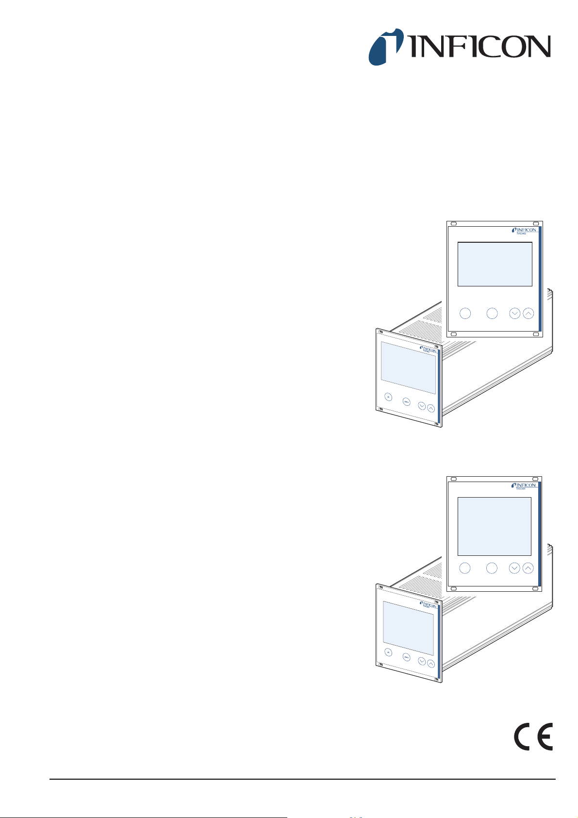
VGC402
Two-Channel Measurement and Control Unit
VGC403
Three-Channel Measurement and Control Unit
tinb07e1-e 2011-07 1
Page 2

Contents
1 Introduction
1.1 Validity . . . . . . . . . . . . . . . . . . . . . . . . . . . . . 4
1.1.1 Part number . . . . . . . . . . . . . . . . . . . . . . . . . . 4
1.1.2 Firmware version . . . . . . . . . . . . . . . . . . . . . . 4
1.1.3 Type label . . . . . . . . . . . . . . . . . . . . . . . . . . . 4
1.2 Intended use. . . . . . . . . . . . . . . . . . . . . . . . . 4
1.2.1 Liability and warranty . . . . . . . . . . . . . . . . . . . 4
1.3 Product versions . . . . . . . . . . . . . . . . . . . . . 4
1.4 Safety . . . . . . . . . . . . . . . . . . . . . . . . . . . . . . 5
1.4.1 Personnel qualifications . . . . . . . . . . . . . . . . . 5
1.4.2 Illustration of residual dangers . . . . . . . . . . . . 5
1.4.3 General safety instructions . . . . . . . . . . . . . . 5
1.4.4 Disconnecting device . . . . . . . . . . . . . . . . . . . 6
2 Technical data
2.1 General data . . . . . . . . . . . . . . . . . . . . . . . . . 7
2.1.1 Mechanical data. . . . . . . . . . . . . . . . . . . . . . . 7
2.1.2 Ambience . . . . . . . . . . . . . . . . . . . . . . . . . . . . 7
2.1.3 Operation . . . . . . . . . . . . . . . . . . . . . . . . . . . . 7
2.2 Mains connection. . . . . . . . . . . . . . . . . . . . . 7
3.3.6 CONTROL . . . . . . . . . . . . . . . . . . . . . . . . . . 14
3.3.7 RS232C . . . . . . . . . . . . . . . . . . . . . . . . . . . . 14
4 Operation
4.1 Front panel . . . . . . . . . . . . . . . . . . . . . . . . . 15
4.1.1 Display . . . . . . . . . . . . . . . . . . . . . . . . . . . . . 15
4.1.2 Control buttons. . . . . . . . . . . . . . . . . . . . . . . 15
4.2 Switching on and off . . . . . . . . . . . . . . . . . 16
4.2.1 Switching on. . . . . . . . . . . . . . . . . . . . . . . . . 16
4.2.2 Switching off. . . . . . . . . . . . . . . . . . . . . . . . . 16
4.2.3 Waiting time . . . . . . . . . . . . . . . . . . . . . . . . . 16
4.3 Operating modes . . . . . . . . . . . . . . . . . . . . 16
4.4 Measurement mode . . . . . . . . . . . . . . . . . . 17
4.4.1 Selection . . . . . . . . . . . . . . . . . . . . . . . . . . . 17
4.4.2 Description . . . . . . . . . . . . . . . . . . . . . . . . . . 17
4.4.3 Control button functions . . . . . . . . . . . . . . . . 17
4.5 Parameter mode. . . . . . . . . . . . . . . . . . . . . 19
4.5.1 Selection . . . . . . . . . . . . . . . . . . . . . . . . . . . 19
4.5.2 Parameter groups . . . . . . . . . . . . . . . . . . . . 19
4.5.3 Basic operation . . . . . . . . . . . . . . . . . . . . . . 20
2.3 Channels. . . . . . . . . . . . . . . . . . . . . . . . . . . . 8
2.3.1 Sensor connections . . . . . . . . . . . . . . . . . . . . 8
2.3.2 Sensor supply . . . . . . . . . . . . . . . . . . . . . . . . 8
2.3.3 Measuring technique . . . . . . . . . . . . . . . . . . . 8
2.4 Switching functions. . . . . . . . . . . . . . . . . . . 8
2.4.1 Switching function relay . . . . . . . . . . . . . . . . . 9
2.4.2 Error signal relay . . . . . . . . . . . . . . . . . . . . . . 9
2.5 Outputs . . . . . . . . . . . . . . . . . . . . . . . . . . . . . 9
2.5.1 Analog output. . . . . . . . . . . . . . . . . . . . . . . . . 9
2.5.2 Recorder output . . . . . . . . . . . . . . . . . . . . . . . 9
2.5.3 Computer interface . . . . . . . . . . . . . . . . . . . . 9
2.6 Scope of delivery . . . . . . . . . . . . . . . . . . . . . 9
3Installation
3.1 Unpacking. . . . . . . . . . . . . . . . . . . . . . . . . . 10
3.2 Mechanical installation . . . . . . . . . . . . . . . 10
3.2.1 Desktop unit . . . . . . . . . . . . . . . . . . . . . . . . . 10
3.2.2 Control panel mounted. . . . . . . . . . . . . . . . . 10
3.2.3 Mounting the unit in a rack. . . . . . . . . . . . . . 11
3.3 Connecting . . . . . . . . . . . . . . . . . . . . . . . . . 11
3.3.1 Back side of the device . . . . . . . . . . . . . . . . 11
3.3.2 Mains connection . . . . . . . . . . . . . . . . . . . . . 12
3.3.3 Ground . . . . . . . . . . . . . . . . . . . . . . . . . . . . . 12
3.3.4 SENSOR . . . . . . . . . . . . . . . . . . . . . . . . . . . 12
3.3.5 RELAY . . . . . . . . . . . . . . . . . . . . . . . . . . . . . 13
5 Parameter
5.1 Switching function parameters (PArA SP)21
5.1.1 Fundamental terms . . . . . . . . . . . . . . . . . . . 21
5.1.2 Configuring switching functions . . . . . . . . . . 22
5.1.3 Adjustment range. . . . . . . . . . . . . . . . . . . . . 22
5.2 Sensor parameters (PArA SEn). . . . . . . . . 23
5.2.1 Measurement filter (FiLt) . . . . . . . . . . . . . . . 23
5.2.2 Gas type (GAS) . . . . . . . . . . . . . . . . . . . . . . 24
5.2.3 Measuring range (FS) . . . . . . . . . . . . . . . . . 24
5.2.4 Offset (oFS) . . . . . . . . . . . . . . . . . . . . . . . . . 24
5.2.5 Degas function (dEGAS) . . . . . . . . . . . . . . . 25
5.2.6 Sensor activation (S-on) . . . . . . . . . . . . . . . 25
5.2.7 Switch-on threshold (t-on) . . . . . . . . . . . . . . 25
5.2.8 Sensor deactivation (S-oFF) . . . . . . . . . . . . 25
5.2.9 Switch-off threshold (t-off) . . . . . . . . . . . . . . 26
5.2.10 Emission (EMi) . . . . . . . . . . . . . . . . . . . . . . . 26
5.2.11 Filament selection (FiL) . . . . . . . . . . . . . . . . 26
5.2.12 Pirani range extension (PrE) . . . . . . . . . . . . 26
5.3 General parameters (PArA GEn) . . . . . . . . 27
5.3.1 Unit of measurement (unit) . . . . . . . . . . . . . 27
5.3.2 Baud rate (bAud) . . . . . . . . . . . . . . . . . . . . . 27
5.3.3 Display format (diGit) . . . . . . . . . . . . . . . . . . 27
5.3.4 Default parameters (dEF). . . . . . . . . . . . . . . 27
5.3.5 Recorder output (Ao) . . . . . . . . . . . . . . . . . . 27
5.3.6 Error signal relay (Err-r) . . . . . . . . . . . . . . . . 29
5.4 Test parameters (PArA tESt) . . . . . . . . . . . 29
2 tinb07e1-e 2011-07 Vacuum Gauge Controller
Page 3

5.4.1 Selection . . . . . . . . . . . . . . . . . . . . . . . . . . . 29
5.4.2 Firmware version (Pnr) . . . . . . . . . . . . . . . . 29
5.4.3 Watchdog control (dt-C). . . . . . . . . . . . . . . . 29
5.4.4 Torr lock (tr-L) . . . . . . . . . . . . . . . . . . . . . . . 30
5.4.5 Parameter setup lock (LoC) . . . . . . . . . . . . . 30
5.4.6 RAM test (rA-t). . . . . . . . . . . . . . . . . . . . . . . 30
5.4.7 EPROM test (EP-t). . . . . . . . . . . . . . . . . . . . 30
5.4.8 EEPROM test (EE-t) . . . . . . . . . . . . . . . . . . 30
5.4.9 Display test (di-t) . . . . . . . . . . . . . . . . . . . . . 30
5.4.10 A/D converter signal (Ad-S). . . . . . . . . . . . . 30
5.4.11 A/D converter ID (Ad-i) . . . . . . . . . . . . . . . . 31
5.4.12 I/O test (io-t). . . . . . . . . . . . . . . . . . . . . . . . . 31
5.4.13 RS232C test (rS-t) . . . . . . . . . . . . . . . . . . . . 31
6 Computer interface
6.1 Basics . . . . . . . . . . . . . . . . . . . . . . . . . . . . . 32
6.1.1 Connection. . . . . . . . . . . . . . . . . . . . . . . . . . 32
6.1.2 Nomenclature . . . . . . . . . . . . . . . . . . . . . . . 32
6.2 Communication . . . . . . . . . . . . . . . . . . . . . 32
6.2.1 Protocol . . . . . . . . . . . . . . . . . . . . . . . . . . . . 32
6.2.2 Sending (Host --> Unit) . . . . . . . . . . . . . . . . 32
6.2.3 Receiving (Unit --> Host) . . . . . . . . . . . . . . . 33
6.2.4 Examples . . . . . . . . . . . . . . . . . . . . . . . . . . . 33
6.2.5 Number formats . . . . . . . . . . . . . . . . . . . . . . 33
6.2.6 Continuous transmission of measurements. 33
6.3.31 TEE . . . . . . . . . . . . . . . . . . . . . . . . . . . . . . . 42
6.3.32 TEP . . . . . . . . . . . . . . . . . . . . . . . . . . . . . . . 42
6.3.33 TID . . . . . . . . . . . . . . . . . . . . . . . . . . . . . . . . 43
6.3.34 TIO . . . . . . . . . . . . . . . . . . . . . . . . . . . . . . . . 43
6.3.35 TKB . . . . . . . . . . . . . . . . . . . . . . . . . . . . . . . 43
6.3.36 TLC . . . . . . . . . . . . . . . . . . . . . . . . . . . . . . . 44
6.3.37 TRA . . . . . . . . . . . . . . . . . . . . . . . . . . . . . . . 44
6.3.38 TRS . . . . . . . . . . . . . . . . . . . . . . . . . . . . . . . 44
6.3.39 UNI. . . . . . . . . . . . . . . . . . . . . . . . . . . . . . . . 44
6.3.40 WDT. . . . . . . . . . . . . . . . . . . . . . . . . . . . . . . 44
7 Maintenance and service
7.1 Maintenance . . . . . . . . . . . . . . . . . . . . . . . . 45
7.1.1 Cleaning. . . . . . . . . . . . . . . . . . . . . . . . . . . . 45
7.2 Program transfer mode . . . . . . . . . . . . . . . 45
7.2.1 Preparations and selection . . . . . . . . . . . . . 45
7.2.2 Program transfer . . . . . . . . . . . . . . . . . . . . . 45
7.2.3 Restarting . . . . . . . . . . . . . . . . . . . . . . . . . . 45
7.3 Calibration . . . . . . . . . . . . . . . . . . . . . . . . . 46
7.3.1 Basics . . . . . . . . . . . . . . . . . . . . . . . . . . . . . 46
7.3.2 CAO . . . . . . . . . . . . . . . . . . . . . . . . . . . . . . . 46
7.3.3 CAF . . . . . . . . . . . . . . . . . . . . . . . . . . . . . . . 46
7.3.4 Calibrating the unit . . . . . . . . . . . . . . . . . . . . 46
6.3 Mnemonics . . . . . . . . . . . . . . . . . . . . . . . . . 34
6.3.1 Overview . . . . . . . . . . . . . . . . . . . . . . . . . . . 34
6.3.2 AOM. . . . . . . . . . . . . . . . . . . . . . . . . . . . . . . 35
6.3.3 BAU . . . . . . . . . . . . . . . . . . . . . . . . . . . . . . . 35
6.3.4 COM . . . . . . . . . . . . . . . . . . . . . . . . . . . . . . 35
6.3.5 COR. . . . . . . . . . . . . . . . . . . . . . . . . . . . . . . 36
6.3.6 DCD . . . . . . . . . . . . . . . . . . . . . . . . . . . . . . . 36
6.3.7 DGS . . . . . . . . . . . . . . . . . . . . . . . . . . . . . . . 36
6.3.8 ERA . . . . . . . . . . . . . . . . . . . . . . . . . . . . . . . 36
6.3.9 ERR . . . . . . . . . . . . . . . . . . . . . . . . . . . . . . . 36
6.3.10 EUM. . . . . . . . . . . . . . . . . . . . . . . . . . . . . . . 37
6.3.11 FIL . . . . . . . . . . . . . . . . . . . . . . . . . . . . . . . . 37
6.3.12 FSR . . . . . . . . . . . . . . . . . . . . . . . . . . . . . . . 37
6.3.13 FUM . . . . . . . . . . . . . . . . . . . . . . . . . . . . . . . 38
6.3.14 GAS . . . . . . . . . . . . . . . . . . . . . . . . . . . . . . . 38
6.3.15 HVC . . . . . . . . . . . . . . . . . . . . . . . . . . . . . . . 38
6.3.16 ITR . . . . . . . . . . . . . . . . . . . . . . . . . . . . . . . . 38
6.3.17 LOC . . . . . . . . . . . . . . . . . . . . . . . . . . . . . . . 38
6.3.18 OFC . . . . . . . . . . . . . . . . . . . . . . . . . . . . . . . 39
6.3.19 OFD . . . . . . . . . . . . . . . . . . . . . . . . . . . . . . . 39
6.3.20 PNR . . . . . . . . . . . . . . . . . . . . . . . . . . . . . . . 39
6.3.21 PR1 . . . . . . . . . . . . . . . . . . . . . . . . . . . . . . . 39
6.3.22 PRE . . . . . . . . . . . . . . . . . . . . . . . . . . . . . . . 40
6.3.23 PRX . . . . . . . . . . . . . . . . . . . . . . . . . . . . . . . 40
6.3.24 RES . . . . . . . . . . . . . . . . . . . . . . . . . . . . . . . 40
6.3.25 SAV . . . . . . . . . . . . . . . . . . . . . . . . . . . . . . . 40
6.3.26 SC1 . . . . . . . . . . . . . . . . . . . . . . . . . . . . . . . 41
6.3.27 SP1 . . . . . . . . . . . . . . . . . . . . . . . . . . . . . . . 41
6.3.28 SPS . . . . . . . . . . . . . . . . . . . . . . . . . . . . . . . 41
6.3.29 TAD . . . . . . . . . . . . . . . . . . . . . . . . . . . . . . . 42
6.3.30 TDI . . . . . . . . . . . . . . . . . . . . . . . . . . . . . . . . 42
8 Troubleshooting
8.1 Fault indication . . . . . . . . . . . . . . . . . . . . . 48
8.2 Error messages . . . . . . . . . . . . . . . . . . . . . 48
8.3 Technical support . . . . . . . . . . . . . . . . . . . 48
9 Storage and disposal
9.1 Packaging . . . . . . . . . . . . . . . . . . . . . . . . . . 49
9.2 Storage . . . . . . . . . . . . . . . . . . . . . . . . . . . . 49
9.3 Disposal . . . . . . . . . . . . . . . . . . . . . . . . . . . 49
Appendix
Conversion tables . . . . . . . . . . . . . . . . . . . 50
Weights . . . . . . . . . . . . . . . . . . . . . . . . . . . . 50
Pressure . . . . . . . . . . . . . . . . . . . . . . . . . . . 50
Linear measures . . . . . . . . . . . . . . . . . . . . . 50
Temperature . . . . . . . . . . . . . . . . . . . . . . . . 50
Default parameters . . . . . . . . . . . . . . . . . . 51
Literature . . . . . . . . . . . . . . . . . . . . . . . . . . 51
Index . . . . . . . . . . . . . . . . . . . . . . . . . . . . . . 52
ETL Certification . . . . . . . . . . . . . . . . . . . . 55
EC Declaration of Conformity. . . . . . . . . . 55
tinb07e1-e 2011-07 Vacuum Gauge Controller 3
Page 4

1 Introduction
Model:
PN:
SN:
V Hz W
1.1 Validity
1.1.1 Part number
This document applies to the following products:
Part number Product
398-020 VGC402
398-021 VGC403
The part number can be found on the type label which is
attached to one side of the unit.
1.1.2 Firmware version
This Operating Manual is based on the firmware version
302-534-D.
If the unit does not work as described, please check if it
is equipped with this firmware version. See Chapter 5.4.2
Firmware version (Pnr), 29.
1.1.3 Type label
There is a type label attached to one side of the unit. In
all communication with INFICON, please state the information on the type label. For this purpose you may want
to copy the information into the space provided below:
1.2 Intended use
The VGC402 and VGC403 Vacuum Gauge Controller is
a display and control unit for vacuum gauges made by
INFICON.
It is used together with vacuum gauges of the PSG, PCG,
PEG, MPG, CDG, BPG, BCG and HPG series and is
used for total pressure measurements. The vacuum
gauges must be operated in accordance with their
respective operating manuals.
In the following, the VGC402 or VGC403 Vacuum Gauge
Controller will be referred to as «Vacuum Gauge Controller».
1.2.1 Liability and warranty
INFICON assumes no liability and the warranty becomes
null and void if the end user or third parties
• Disregard the information in this document
• Use the product in a non-conforming manner
• Make any kind of alterations (modifications, repair
work, etc.) to the product
• Use the product with accessories not listed in the corresponding product documentation
We reserve the right to make technical changes without
prior notice. The figures are non-committal.
1.3 Product versions
The Vacuum Gauge Controller is available in two different versions: VGC402 and VGC403. The two products
differ from each other with regard to:
• Number of channels
Fig. 1-1 Type label (example)
4 tinb07e1-e 2011-07 Vacuum Gauge Controller
• Number of switching functions
• Power consumption
• Weight
See Chapter 2 Technical data, 7.
This Operating Manual describes both the VGC402 and
the VGC403.
Page 5
1.4 Safety
1.4.1 Personnel qualifications
All work described in this document may only be carried
out by persons who have suitable technical training and
the necessary experience or who have been instructed
by the end user of the product.
1.4.3 General safety instructions
For all work you are going to do, adhere to the applicable
safety regulations.
Also observe all safety notes given in this document and
forward the information to all other users of the product.
In particular, pay attention to the following safety notes:
1.4.2 Illustration of residual dangers
This Operating Manual illustrates safety notes concerning residual dangers as follows:
DANGER
DANGER indicates an imminently hazardous
situation which, if not avoided, will result in
death or severe injury.
WARNING
WARNING indicates a potentially hazardous
situation which, if not avoided, could result in
death or severe injury.
CAUTION
CAUTION indicates a potentially hazardous
situation which, if not avoided, may result in
moderate or minor injury or in property damage.
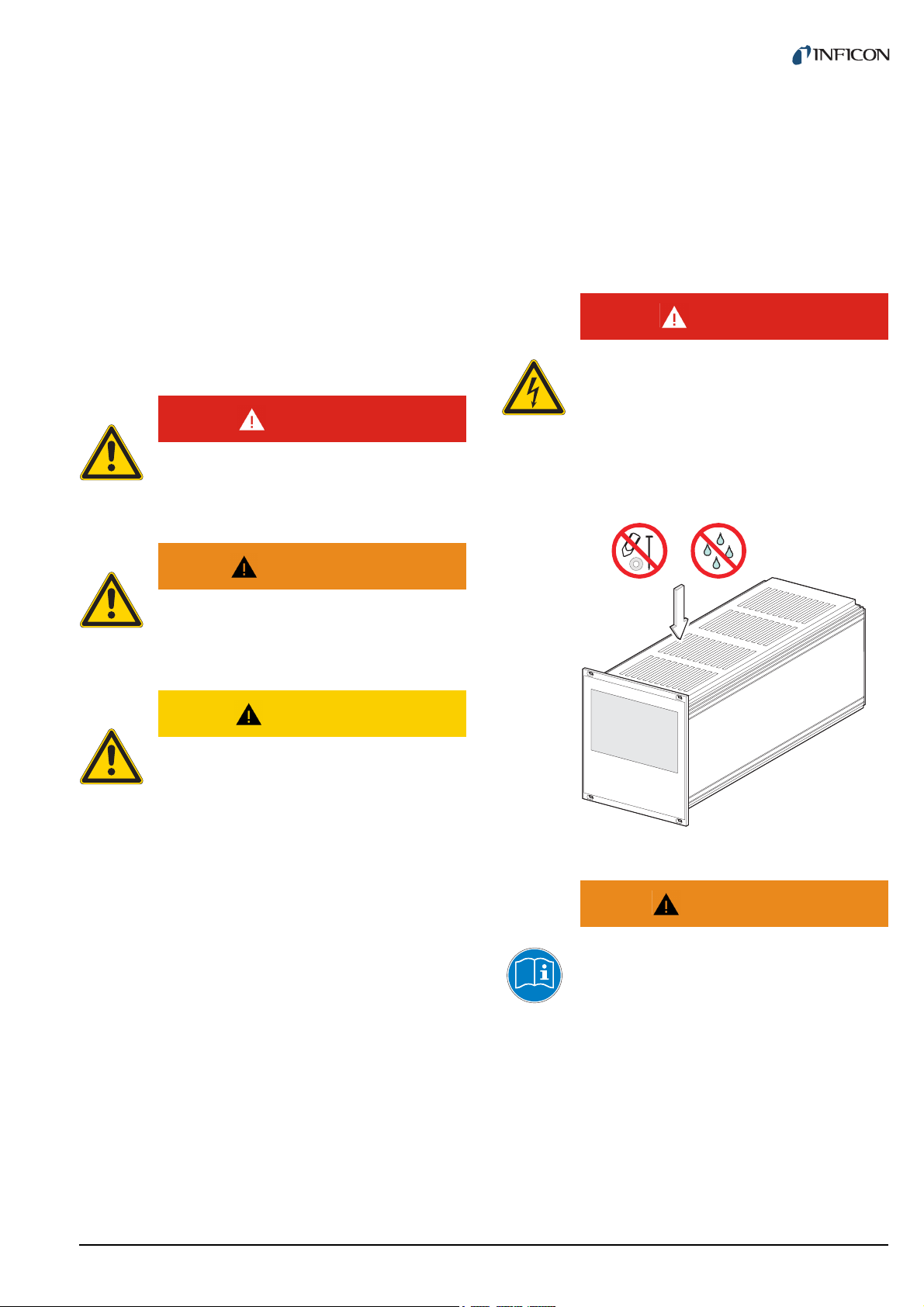
DANGER
Mains power.
The Vacuum Gauge Controller contains parts
which are connected to the mains supply.
Make sure that no objects enter through the
louvers of the unit. Keep the unit dry. Do not
open the unit.
NOTE:
A note such as this one indicates particularly important, but not safety-relevant information.
Fig. 1-2 Do not insert objects through louvers and keep unit dry
WARNING
Improper use.
Improper use can damage the Vacuum
Gauge Controller.
Use the Vacuum Gauge Controller only as intended by the manufacturer. See Chapter 1.2
Intended use, 4.
tinb07e1-e 2011-07 Vacuum Gauge Controller 5
Page 6
WARNING
A
Improper installation and operation data.
Improper installation and operation data may
damage the Vacuum Gauge Controller.
Strictly adhere to the stipulated installation
and operation data.
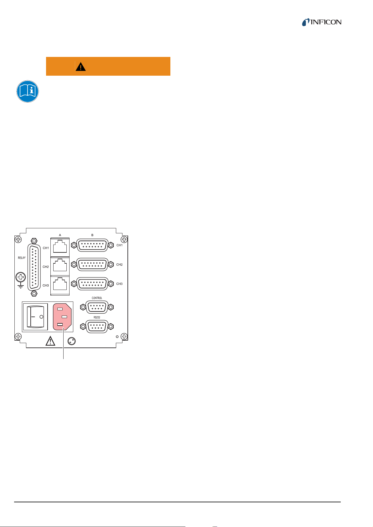
1.4.4 Disconnecting device
The Vacuum Gauge Controller is equipped with a disconnecting device according to EN 61010-1.
The disconnecting device is located at the back of the
Vacuum Gauge Controller. See Fig. 1-3, 6.
The disconnecting device must be readily identifiable and
easily reached by the user.
In order to disconnect the Vacuum Gauge Controller from
mains, you must unplug the mains cable.
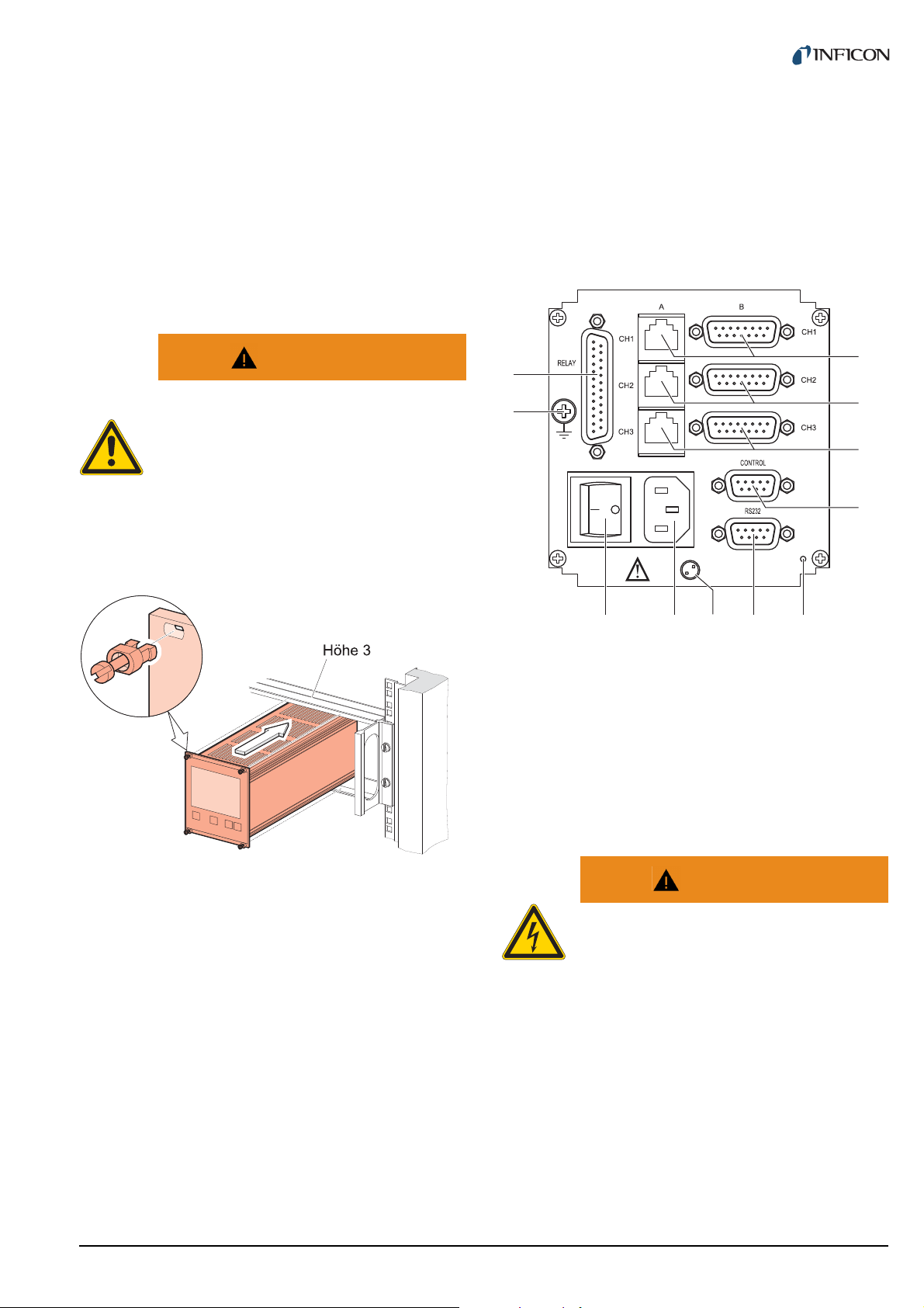
Fig. 1-3 Back side of the VGC403
A Disconnecting device
6 tinb07e1-e 2011-07 Vacuum Gauge Controller
Page 7

2 Technical data
106.3
91.4
3.5
122.5
128.5
103
110
285
204.5
2.5
2.1 General data
2.1.1 Mechanical data
Dimensions Width: 106.3 mm
Height: 128.5 mm (3 HE)
Depth: 207 mm
See Fig. 2-1, 7
Weight VGC402:
1.04 kg
VGC403:
1.16 kg
Use Desktop unit
Control panel mounted
Mounting the unit in a rack
2.1.2 Ambience
Temperature Storage: -20… +60 °C
Operation: +5…+50 °C
Relative humidity Max. 80 % (bis 31 °C),
decreasing to
max. 50 % (above 40 °C)
Use Indoors only
Altitude max. 2000 m NN
Pollution degree II
Protection type IP20
2.1.3 Operation
Manually Via 4 control buttons on the
front panel
Remote control Via RS232C interface
Fig. 2-1 Dimensions (in mm)
2.2 Mains connection
Voltage 90…250 VAC
Frequency 50…60 Hz
Power consumption VGC402:
Max. 45 W
VGC403:
Max. 65 W
Overvoltage category II
Protection class 1
Connection European appliance con-
nector IEC 320 C14
tinb07e1-e 2011-07 Vacuum Gauge Controller 7
Page 8

2.3 Channels
2.3.3 Measuring technique
2.3.1 Sensor connections
Number of channels VGC402: 2
VGC403: 3
Sensor connections per
channel
Compatible sensors Pirani:
RJ45 (FCC 68)
D-Sub, 15 pins, female
(connected in parallel)
PSG400, PSG400-S,
PSG100-S, PSG101-S,
PSG500, PSG500-S,
PSG502-S, PSG510-S,
PSG512-S, PSG550,
PSG552, PSG554
Pirani / Capacitance:
PCG400, PCG400-S,
PCG550, PCG552, PCG554
Cold cathode:
PEG100
Cold cathode / Pirani:
MPG400, MPG401
Capacitance:
CDG025, CDG025D,
CDG045, CDG045D,
CDG100, CDG100D,
CDG160D
Hot ionization / Pirani:
BPG400, BPG402
HPG400
Hot ionization / Pirani /
Capacitance: BCG450
Measuring ranges Sensor dependent
Error of measurement Gain error:
≤ 0.005 % FS
Offset error:
≤ 0.01 % FS
-1
Measuring rate 50 s
Display rate 10 s
Filter time constant Slow:
Unit of measurement mbar, Pa, Torr, Micron
Possible adjustments Linear sensors (CDG):
A/D converter Resolution > 16 bit
NOTE:
The measurements of the BPG/BCG/HPG/CDGxxxD
are transferred digitally.
-1
Approx. 1.0 s (f
Normal (nor):
Approx. 0.3 s (f
Fast:
Approx. 0.06 s (f
Zero-adjust
Logarithmic sensors (PSG,
PCG, PEG, MPG, BPG,
BCG, HPG):
Fixed correction factors for
, Ar, H2, or a variable cor-
N
2
rection factor in the range
0.10…9.99
= 0.16 Hz)
g
= 0.53 Hz)
g
= 2.65 Hz)
g
2.3.2 Sensor supply
2.4 Switching functions
Voltage +24 VDC ±5 %
Current 500 mA
(750 mA short-time)
Fuse 900 mA via PTC element
Self-resetting after switching
the unit off or unplugging the
sensor.
The supply meets the
requirements of a ground
protective extra low voltage
(SELV).
8 tinb07e1-e 2011-07 Vacuum Gauge Controller
Number of switching
functions
Assignment Can be configured any way
Delay time Filter time constant depen-
Adjustment range Sensor dependent
Hysteresis Linear sensors (CDG): ≥ 1
VGC402: 4
VGC403: 6
dent
% FS
Logarithmic sensors (PSG,
PCG, PEG, MPG, BPG,
BCG, HPG):
≥ 10 % of measurement
Page 9

2.4.1 Switching function relay
2.5.2 Recorder output
Contact type Change-over contact, float-
ing
Load (ohmic) Max. 60 VDC, 0.5 A
Max. 30 VAC, 1 A
Lifetime Mechanical:
Connection D-sub, 25 pins, female.
7
cycles
10
Electrical:
5
cycles at maximum load
10
See Fig. 3-8, 13.
2.4.2 Error signal relay
Number 1
Delay time ≤ 20 ms
Contact type Change-over contact, float-
ing
Load (ohmic) Max. 60 VDC, 0.5 A
Max. 30 VAC, 1 A
Lifetime Mechanical:
7
cycles
10
Electrical:
5
cycles at maximum load
10
Number 1
Voltage range 0…10 VDC
Resolution 1 mV
Accuracy ± 20 mV
Internal resistance 3300 Ω
Relation between
voltage and pressure
Connection D-Sub, 9 pins, male.
Programmable
See Fig. 3-9, 14.
2.5.3 Computer interface
Default RS232C
Protocol ACK/NAK
ASCII with 3-character mnemonics. Bidirectional data
flow.
Signals Only TXD and RXD used
Baud rate 9600, 19200, 38400
Connection D-Sub, 9 pins, female.
See Fig. 3-10, 14.
Connection D-sub, 25 pins, female.
See Fig. 3-8, 13.
2.5 Outputs
2.5.1 Analog output
Number 1 per channel
Voltage range 0…10 VDC
Deviation from
displayed value
Internal resistance 47 Ω
Relation between
voltage and pressure
Connection D-Sub, 9 pins, male.
± 50 mV
Sensor dependent
See Fig. 3-9, 14.
2.6 Scope of delivery
Designation Number
Vacuum Gauge Controller
Mains cable 1
Rubber strip
Rubber feet
Collar screws
Plastic sleeves
CD-ROM manual 1
EC Declaration of Conformity
Installation manual 1
1
1
2
4
4
1
tinb07e1-e 2011-07 Vacuum Gauge Controller 9
Page 10
3 Installation
105
91.4
122.5
112
M3 (ø3.5)
3.1 Unpacking
1 Visually inspect the transport packaging for signs
of external damage
2 Unpack the Vacuum Gauge Controller and put the
packaging material aside
NOTE:
Keep the packaging material for later use. The Vacuum Gauge Controller must be stored and transported
in the original packaging material only.
3 Examine the Vacuum Gauge Controller for com-
pleteness
4 Visually inspect the Vacuum Gauge Controller for
signs of damage
WARNING
Damaged product.
Putting a damaged product into operation can
be extremely dangerous.
Never attempt to put a damaged product into
operation. Secure the damaged product from
unintended operation. Send a damage report
to the haulage company or the insurer.
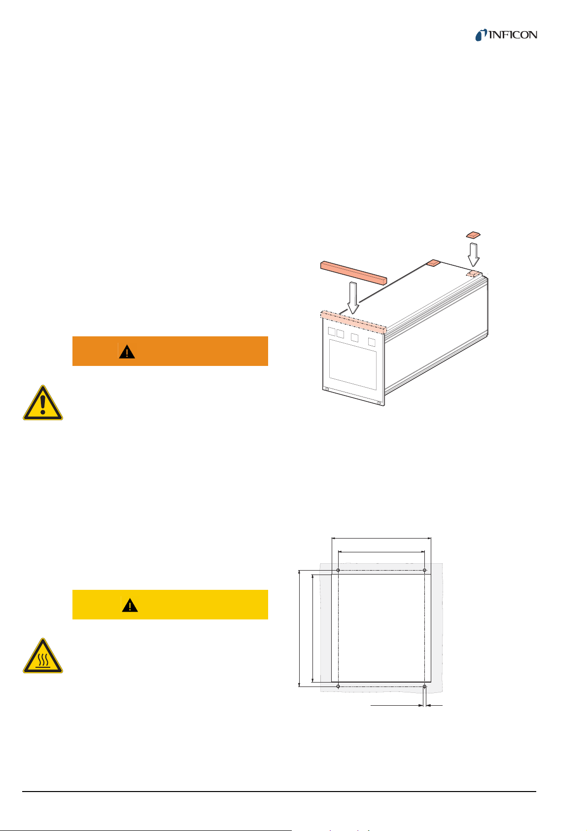
1 Turn the Vacuum Gauge Controller upside down
as shown in Fig. 3-1, 10
2 Push the supplied rubber strip onto the lower edge
of the front panel
3 Stick the supplied rubber feet to the bottom of the
casing
Fig. 3-1 Using the product as a desk-top unit
4 Turn the Vacuum Gauge Controller back to normal
orientation and place it on the required location
3.2 Mechanical installation
The Vacuum Gauge Controller can be used as follows:
As a desk-top unit, mounted in a control panel, or
mounted in a 19" rack. In each of these cases you must
pay attention to the following safety note:
CAUTION
Too high ambient temperature.
Exceeding the maximum permitted ambient
temperature may damage the unit.
Make sure that the maximum permitted ambient temperature is not exceeded and that the
air can flow freely through the louvers. Do not
expose the unit to direct sunlight.
3.2.1 Desktop unit
In order to use the Vacuum Gauge Controller as a desktop unit, proceed as follows:
3.2.2 Control panel mounted
In order to mount the unit in a control panel, the following
cutout is required:
Fig. 3-2 Control panel cutout (in mm)
1 Insert the Vacuum Gauge Controller into the cutout
2 Fasten the unit with four M3 screws
10 tinb07e1-e 2011-07 Vacuum Gauge Controller
Page 11
NOTE:
A
B
C
D
EFGH
I
J
K
In order to reduce the strain on the front panel it is
recommended to support the bottom of the unit.
3.3 Connecting
3.3.1 Back side of the device
3.2.3 Mounting the unit in a rack
The Vacuum Gauge Controller is designed for installation
into a rack chassis adapter according to DIN 41 494 (19",
3 HE). For this purpose, 4 collar screws and 4 plastic
sleeves are supplied with the unit.
WARNING
Lower protection class of the rack.
If the product is installed in a rack, it is likely
to lower the protection class of the rack (protection from foreign bodies and water) e.g.
according to the EN 60204-1 regulations for
switching cabinets.
Take appropriate measures to restore the required protection class of the rack.
Fig. 3-4, 11 shows the back side of the VGC403. The
connection for channel 3 (Pos. C) is not available in the
VGC402.
Fig. 3-4 Back side of the VGC403
A Sensor connection, channel 1
B Sensor connection, channel 2
C Sensor connection, channel 3
D CONTROL connection
E Switch for program transfer mode
F RS232C connection
G Mains connection / disconnecting device
HMains switch
I Ground screw
J RELAY connection
K Screw for internal protective conductor. Do not loosen this screw!
Fig. 3-3 Mounting the unit in a rack
WARNING
NOTE:
In order to reduce the strain on the front panel it is
recommended to equip the rack chassis adapter with
a guide rail.
NOTE:
Screw for internal protective conductor.
The internal protective conductor is connected to the casing with a screw (Pos. K).
Do not turn or loosen this screw.
For safe and easy installation of heavy rack chassis
adapters, it is recommended to equip the rack frame
with slide rails.
1 Fasten the rack chassis adapter in the rack
2 Insert the Vacuum Gauge Controller into the rack
chassis adapter
The configuration of the available connections is
described in the following sections.
3 Fasten the Vacuum Gauge Controller with the sup-
plied collar screws and plastic sleeves to the rack
chassis adapter
tinb07e1-e 2011-07 Vacuum Gauge Controller 11
Page 12
3.3.2 Mains connection
1
8
1
8
9
15
3.3.3 Ground
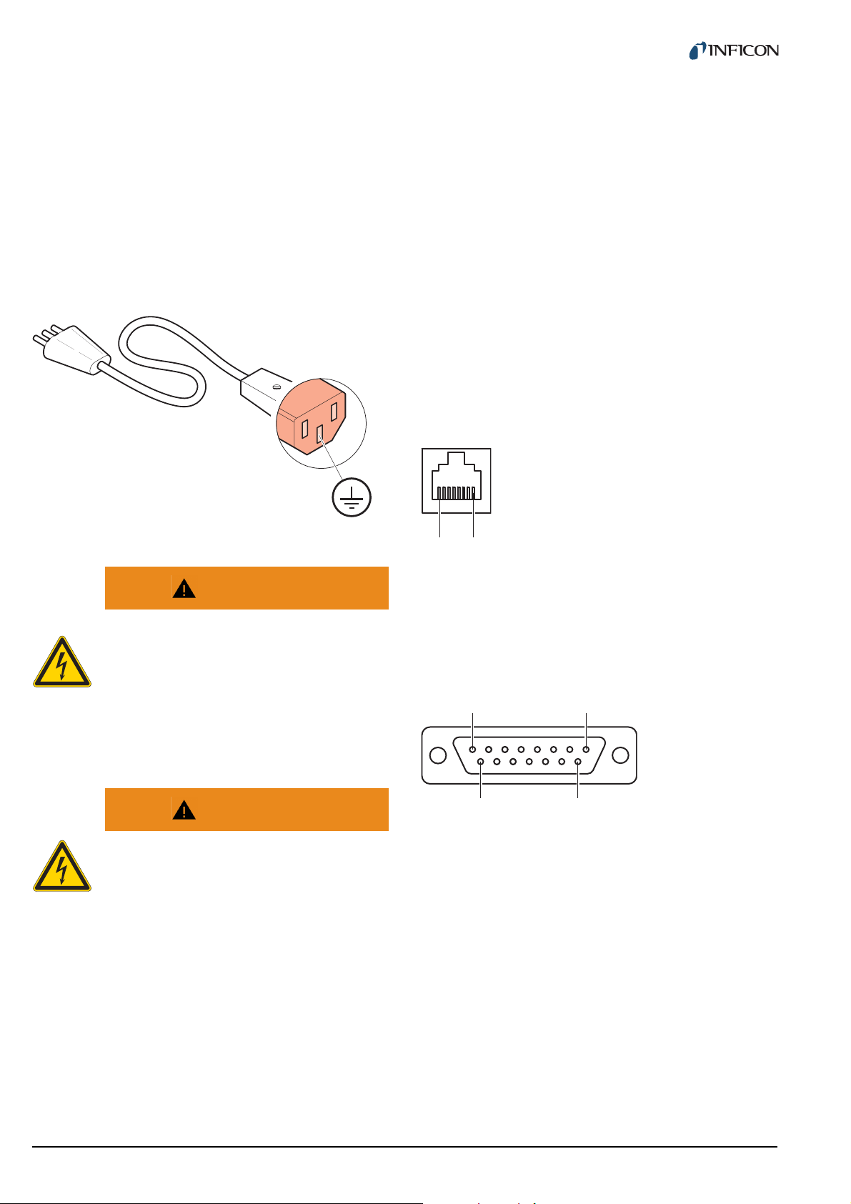
The mains connection (Fig. 3-4, 11, Pos. G) is
designed for a mains cable which contains a European
appliance connector on the device side.
A mains cable is supplied with the unit. If the plug is not
compatible with your wall socket, you have to get a suitable mains cable:
• Three-conductor cable with protective ground
2
• Conductor cross-section 3 × 1.5 mm
Fig. 3-5 Three-conductor cable with protective ground (example)
or larger
The ground screw (Fig. 3-4, 11, Pos. I) can be used to
connect the Vacuum Gauge Controller with the protective
ground of the pumping station.
1 If required: Connect the protective ground of the
pumping station with the ground screw. Use a protective conductor.
3.3.4 SENSOR
The SENSOR connection is used to connect the sensors.
For each channel, there are two connections available
which are connected in parallel: An 8-pin RJ45 appliance
socket and a 15-pin D-Sub appliance socket. See
Fig. 3-4, 11, Pos. A…C.
Pin assignment
WARNING
Mains power.
Improperly grounded devices can be extremely dangerous in the event of a fault.
Use three-wire mains or extension cables
with protective ground only. Plug the mains
cable into wall sockets with protective ground
only.
WARNING
No mains fuse.
The Vacuum Gauge Controller is not
equipped with a mains fuse.
The wall socket must be protected with a fuse
(max. 10 A).
1 Connect the European appliance connector of the
mains cord with the mains connection of the unit
Fig. 3-6 SENSOR appliance socket (RJ45)
1 +24 VDC
2PGND
3 Signal
4 Ident
Fig. 3-7 SENSOR appliance socket (D-Sub, 15-pin)
1 EMI-Status
2 Signal
3 Status
4 HV_EMI
5PGND
6n.c.
7 Degas
8 Supply
5 Signal-GND
6 Status
7HV_L
8 HV_EMI
9n.c.
10 Ident
11 Supply_CDG
12 Signal-GND
13 RXD
14 TXD
15 Chassis
2 Connect the plug of the mains cable with the wall
socket
NOTE:
If the unit is installed in a switching cabinet, the
mains power can be supplied via a switchable central
power distributor.
12 tinb07e1-e 2011-07 Vacuum Gauge Controller
Page 13
CAUTION
1
13
14
25
Improper sensor.
Sensors which are not designed for use with
the Vacuum Gauge Controller may damage
the unit.
Operate the Vacuum Gauge Controller with
proper sensors only. See Chapter 2.3.1 Sensor connections, 8.
CAUTION
Multiple connection.
Only one sensor may be connected to each of
the channels. Otherwise the connected sensors will be damaged.
Never connect more than one sensor per
channel.
Connecting
1 Channel 1: Connect the sensor with to the CH1-A
or CH1-B connection. Use a shielded 1:1 cable.
2 Channel 2: Connect the sensor with to the CH2-A
or CH2-B connection. Use a shielded 1:1 cable.
3 Channel 3: Connect the sensor with to the CH3-A
or CH3-B connection. Use a shielded 1:1 cable.
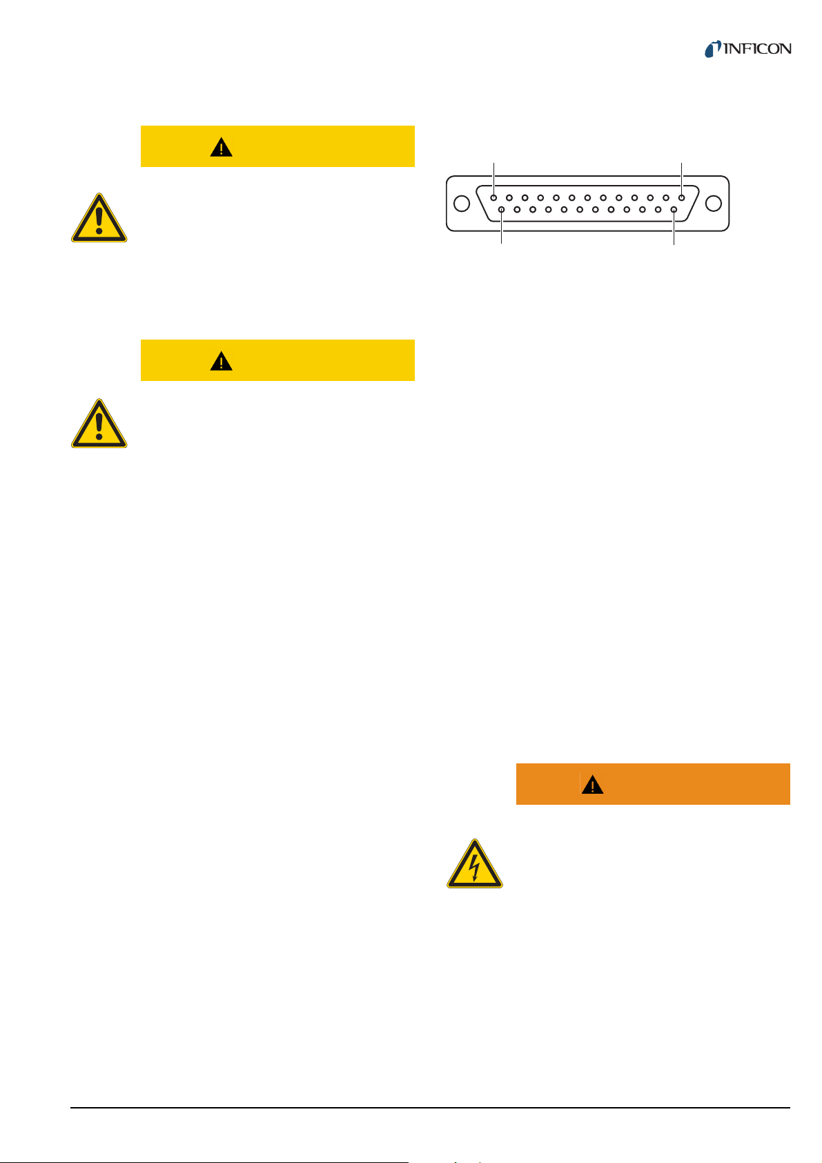
3.3.5 RELAY
The switching functions and the error monitoring system
influence the state of several relays inside of the Vacuum
Gauge Controller. The RELAY connection (Fig. 3-4,
11, Pos. J) allows to utilize the relay contacts for
switching purposes. The relay contacts are potential-free
(floating).
Pin assignment
Fig. 3-8 RELAY appliance socket (D-Sub, 25-pin)
1GND
2n.c.
3 Error break contact (NC)
4 SP 1 break contact (NC)
5 SP 1 common contact
(COM)
6 SP 1 make contact (NO)
7GND
8 SP 2 break contact (NC)
9 SP 2 common contact
(COM)
10 SP 2 make contact (NO)
11 SP 3 break contact (NC)
12 SP 3 common contact
(COM)
13 SP 3 make contact (NO)
n.c. not connected
COM common contact
NC break contact (normally closed)
NO make contact (normally open)
14 Error make contact (NO)
15 Error common contact
(COM)
16 SP 4 break contact (NC)
17 SP 4 common contact
(COM)
18 SP 4 make contact (NO)
19 SP 5 break contact (NC)
20 SP 5 common contact
(COM)
21 SP 5 make contact (NO)
22 SP 6 break contact (NC)
23 SP 6 common contact
(COM)
24 SP 6 make contact (NO)
25 +24 VDC, 200 mA. Meets
the requirements of a ground
protective extra low voltage
(SELV)
NOTE:
Pin 25 is used for supplying relays with a higher
breaking capacity. The supply contact is protected at
200 mA with a PTC element. The element is self-resetting when switching the unit off or unplugging the
RELAY connector.
WARNING
Hazardous voltage.
Voltages above 60 VDC or 30 VAC pose a
shock hazard.
The RELAY connection may be used for
switching voltages of max. 60 VDC or 30 VAC
only. These voltages must meet the requirements of a ground protective extra low voltage (SELV).
1 Connect the peripheral components with the
RELAY connection. Use a shielded connection
cable.
tinb07e1-e 2011-07 Vacuum Gauge Controller 13
Page 14
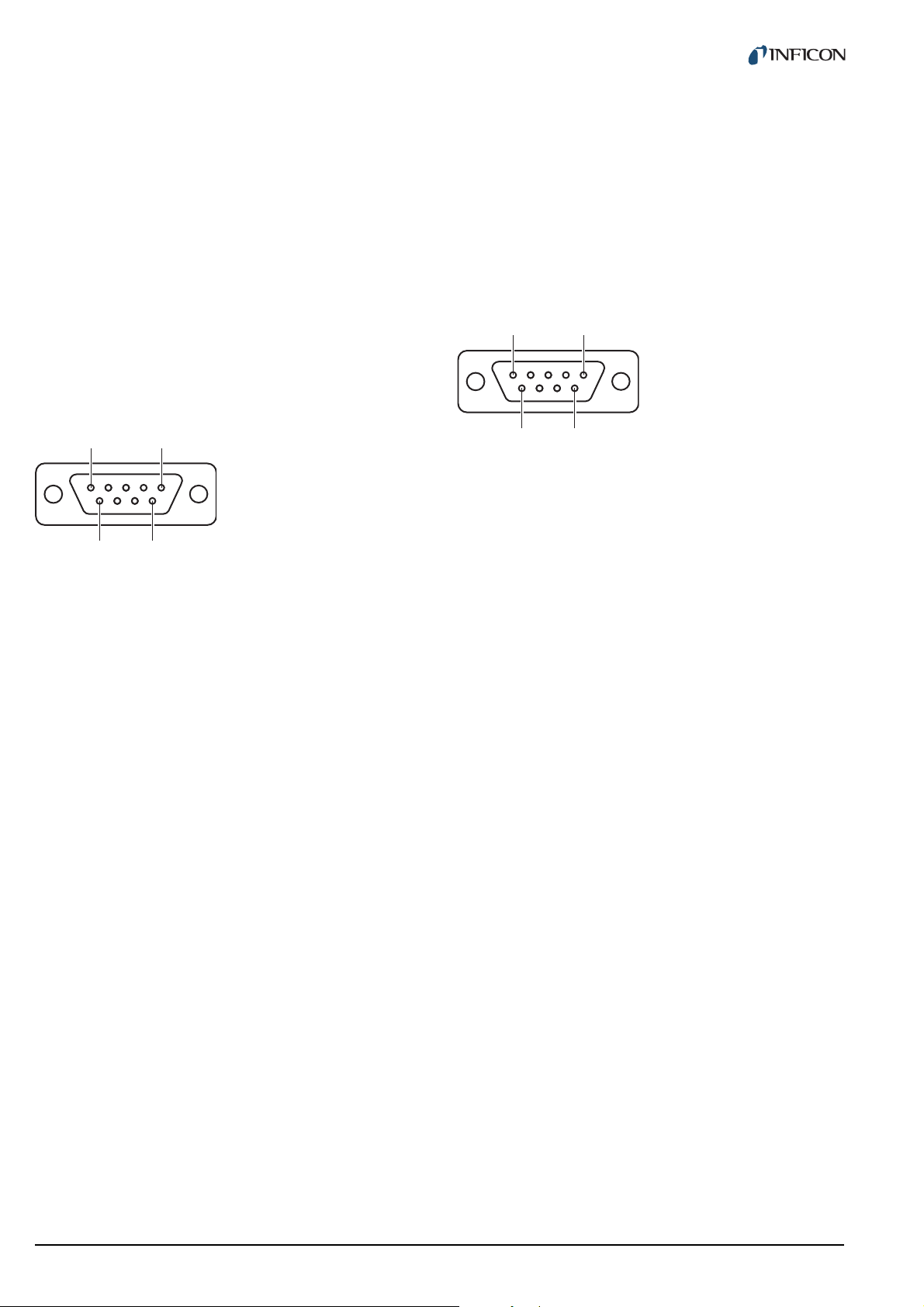
3.3.6 CONTROL
1
5
6 9
1
5
6
9
3.3.7 RS232C
The CONTROL connection (Fig. 3-4, 11, Pos. D) contains the following signal pins:
• Analog outputs for the signals of the individual channels
• Recorder output. This is a programmable analog output which can be assigned to one of the three channels.
• HV-EMI. Used to switch the high-vacuum circuit of the
PEG sensor on and off. The signal levels are: On =
+24 V. Off = 0 V. See Reference [7].
Pin assignment
Fig. 3-9 CONTROL appliance plug (D-Sub, 9-pin)
1 Analog output 1
2 Analog output 3
3GND
4 HV-EMI 3
5 HV-EMI 1
6 Analog output 2
7 Recorder output
8GND
9 HV-EMI 2
1 Connect the peripheral components with the CON-
TROL connection. Use a shielded connection
cable.
The RS232C serial interface (Fig. 3-4, 11, Pos. F)
allows remote control of the unit via a computer or a terminal. See Chapter 6 Computer interface, 32.
In addition, the interface may be used for firmware
updates. See Chapter 7.2 Program transfer mode, 45.
Pin assignment
Fig. 3-10 RS232C appliance socket (D-Sub, 9-pin)
1 n.c. / SUP
2TXD
3RXD
4n.c.
5GND
6DSR
7n.c.
8CTS
9GND
1 Connect the serial interface of the computer with
the RS232C connection. Use a shielded cable.
NOTE:
Use a serial extension cable with a 9-pin plug and a
9-pin socket. The cable must not contain any crossed
wires.
NOTE:
The analog outputs (pins 1, 2, 6) differ from the displayed values by no more than ±50 mV.
14 tinb07e1-e 2011-07 Vacuum Gauge Controller
Page 15
4Operation
parach
ABC
D
E
F
G
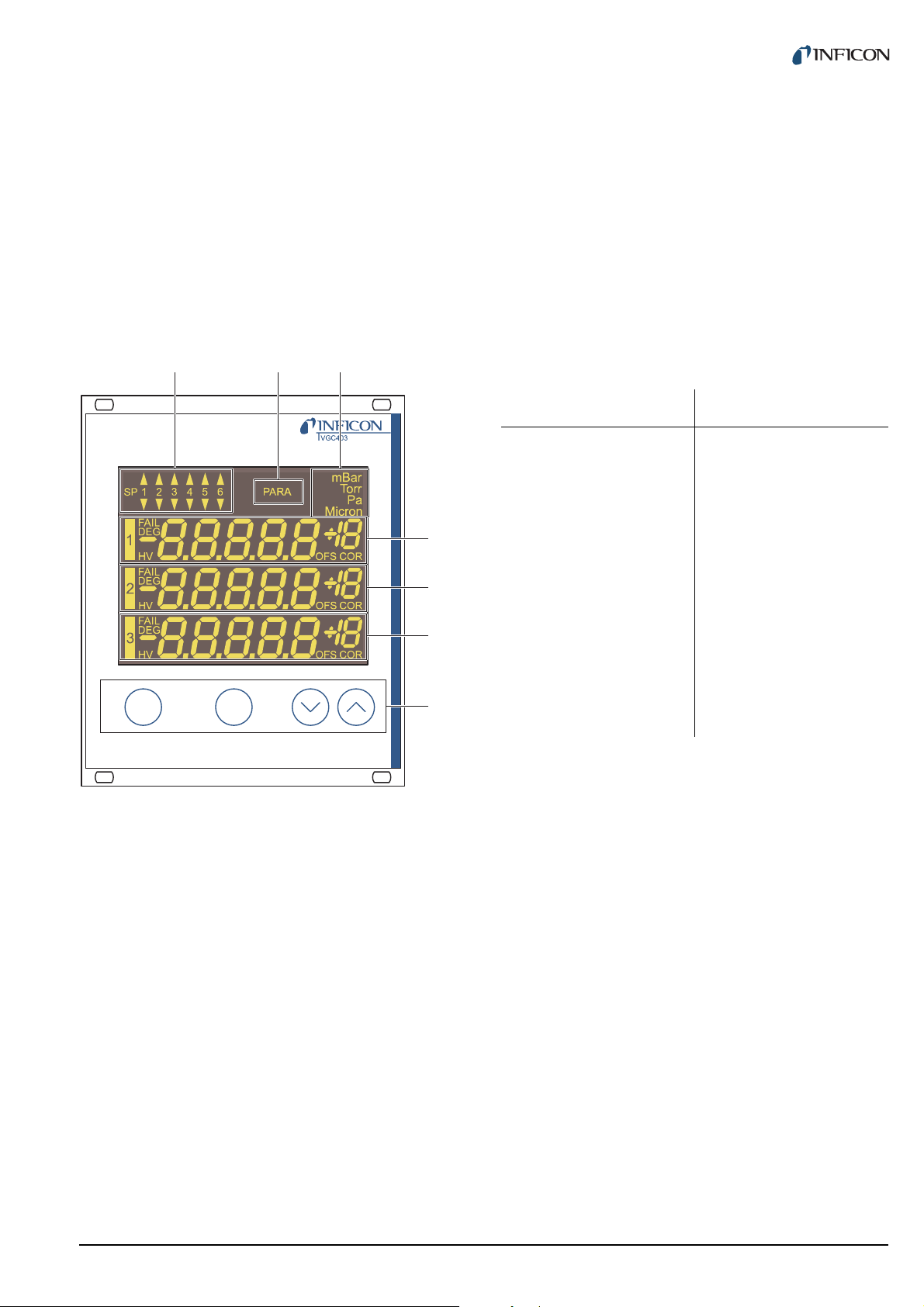
4.1 Front panel
Fig. 4-1, 15 shows the front panel of the VGC403. The
VGC402 is not equipped with the switching points SP5
and SP6 (Pos. A) and the display for the channel 3 (Pos.
F).
Pressure unit
The top right corner (Pos. C) of the display indicates the
pressure unit: mbar, Torr, Pa, or Micron.
Channels
There is a separate display area for each of the available
channels (Pos. D, E, F). From the left to the right, this
area displays the following information:
Display Significance
1, 2, 3 Channel number
FAIL (flashing) Error
DEG (illuminated) Degas function is acti-
vated
HV (illuminated) High-vacuum circuit is
activated
+18
-8.8.8.8.8
Measurement or status
message
OFS (illuminated) Offset correction is acti-
vated
Fig. 4-1 Front panel of the VGC403
A Switching function indicator
B Parameter mode
C Pressure unit
D Display area for channel 1
E Display area for channel 2
F Display area for channel 3
G Control buttons
4.1.1 Display
Switching functions
The top left corner (Pos. A) of the display indicates the
switching function states. An illuminated triangle above a
number indicates that the pressure is above the lower
threshold value. An illuminated triangle below a number
indicates that the pressure is below the upper threshold
value. See Fig. 5-1, 21.
Parameter mode
The PARA indicator (Pos. B) is illuminated when the unit
is set to the parameter mode.
COR (illuminated) Gas type correction is
activated
4.1.2 Control buttons
CH
The CH button is used to select a channel. This may be
necessary e.g. if you want to switch a particular sensor on
or off, or if you want to modify the sensor parameters. The
number of the currently selected channel is flashing for a
few seconds.
PARA
The PARA button is used to select the parameter mode.
The PARA indicator (Pos. B) is illuminated and you can
modify various parameters. See Chapter 4.5 Parameter
mode, 19.
Arrow buttons (DOWN/UP)
The arrow buttons are required for entering data in the
parameter mode. Pressing one of these buttons will
decrease or increase the currently displayed value. In the
following, these buttons will be referred to as DOWN and
UP, respectively.
tinb07e1-e 2011-07 Vacuum Gauge Controller 15
Page 16
4.2 Switching on and off
4.3 Operating modes
4.2.1 Switching on
1 Switch the mains switch on. See Fig. 3-4, 11,
Pos. H.
After switching on, the Vacuum Gauge Controller will perform the following actions:
•Self test
• Identify all sensors
• Restore the previously set parameters
• Activate measurement mode
• Adapt parameters (if a sensor type has changed
meanwhile)
4.2.2 Switching off
1 Switch the mains switch off. See Fig. 3-4, 11,
Pos. H.
4.2.3 Waiting time
CAUTION
Delay time.
The Vacuum Gauge Controller can be set to one of the
following operating modes:
Measurement mode
The measurement mode is the standard operating mode.
It displays the pressure readings of the sensors. In case
of an error, a status message is displayed instead. See
Chapter 4.4 Measurement mode, 17.
Parameter mode
The parameter mode gives you access to various parameters. You can check the parameter settings or modify
them using the arrow buttons. This allows you to configure the Vacuum Gauge Controller. See Chapter 4.5
Parameter mode, 19.
Program transfer mode
The program transfer mode is used to transfer the latest
version of the firmware to the Vacuum Gauge Controller.
See Chapter 7.2 Program transfer mode, 45.
After switching off, the Vacuum Gauge Controller requires approximately 10 seconds to
initialize again.
Wait for at least 10 seconds before you switch
the Vacuum Gauge Controller on again.
NOTE:
If the Vacuum Gauge Controller has been installed in
a control panel or a rack, it can also be switched on
and off via the central power distributor.
16 tinb07e1-e 2011-07 Vacuum Gauge Controller
Page 17
4.4 Measurement mode
parach
parach
parach
4.4.3 Control button functions
4.4.1 Selection
The Vacuum Gauge Controller automatically selects the
measurement mode after it has been switched on.
When the unit is set to the parameter mode, it will automatically return to the measurement mode if no button is
pressed for 10 seconds.
4.4.2 Description
The measurement mode is the standard operating mode.
It displays the pressure readings of the sensors. A status
message is displayed if the pressure exceeds the permissible range. See Tab. 4-1, 17.
Display Pressure
Er Hi Significantly above the permissible
range
The FAIL indicator flashes
The error signal relay switches
Reading In the permissible range
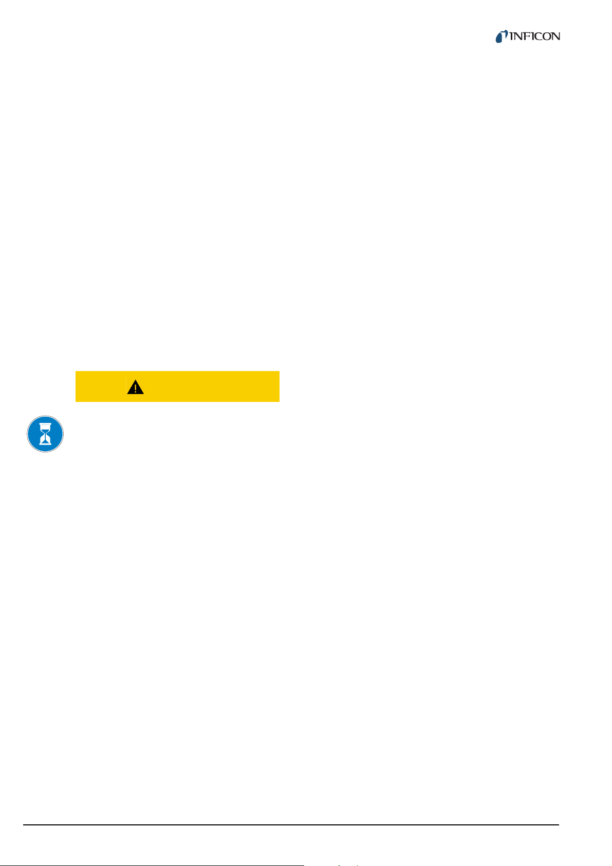
4.4.3.1 Selecting a channel
1 Press the CH button
Fig. 4-2 Pressing the CH button
The unit selects the next channel. The number of the
selected channel is flashing for a few seconds.
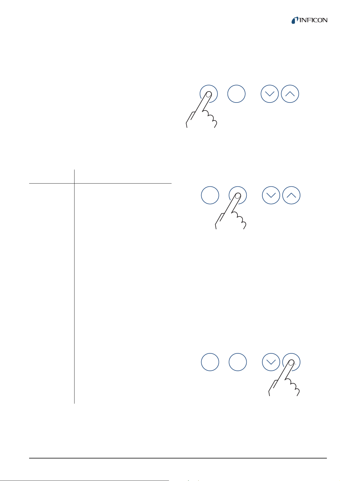
4.4.3.2 Selecting parameter mode
1 Press the PARA button
Er Lo Significantly below the permissible
range
The FAIL indicator flashes
The error signal relay switches
Er x Error message of BPG400/HPG
x = Error code (High-Byte)
Er xx Error message of BCG, BPG402
xxH = Error code
noSEn See Tab. 4-2, 18
noid See Tab. 4-2, 18
oFF See Tab. 5-14, 30
Hot See Chapter 5.2.6, 25
SELF See Chapter 5.2.8, 25
CH 1 See Chapter 5.2.8, 25
CH 2 See Chapter 5.2.8, 25
CH 3 See Chapter 5.2.8, 25
LoC See Chapter 5.4.5, 30
Tab. 4-1 Display when in measurement mode
Channels which are not connected to a sensor display
noSEn. This status message disappears after approximately two minutes.
Fig. 4-3 Pressing the PARA button
The unit changes to the parameter mode. See
Chapter 4.5 Parameter mode, 19. It will automatically
return to the measurement mode if no button is pressed
for 10 seconds.
4.4.3.3 Switching high-vacuum circuit on
The high-vacuum circuit of the following sensors can be
switched on manually: PEG.
For this purpose the sensor control must be set to HAnd.
See Chapter 5.2.6 Sensor activation (S-on), 25.
1 Press the CH button to select the required channel
2 Keep the UP button pressed for approximately 1
second
Fig. 4-4 Press the UP button for 1 second
The sensor on the selected channel is switched on. The
HV indicator is illuminated. The display shows the pressure reading or a status message. See Tab. 4-1, 17.
tinb07e1-e 2011-07 Vacuum Gauge Controller 17
Page 18

4.4.3.4 Switching degas function on
parach
parach
4.4.3.7 Identifying a sensor
The degas function of the following sensors can be
switched on manually: BPG, BCG.
1 Press the CH button to select the required channel
2 Keep the UP button pressed for approximately 1
second. See Fig. 4-4, 17.
The degas function of the sensor on the selected channel
is switched on. The DEG indicator is illuminated.
4.4.3.5 Switching high-vacuum circuit off
The high-vacuum circuit of the following sensors can be
switched off manually: PEG.
For this purpose the sensor control must be set to HAnd.
See Chapter 5.2.8 Sensor deactivation (S-oFF), 25.
1 Press the CH button to select the required channel
2 Keep the DOWN button pressed for approximately
1 second
1 Keep the UP and DOWN buttons pressed for
approximately 1 second
Fig. 4-6 Press the UP and DOWN buttons for 1 second
The display area of the individual sensor shows the connected sensors. See Tab. 4-2, 18.
Display Significance
PSG Pirani gauge (PSG)
PCG Combined gauge
Pirani / Capacitance (PCG)
PEG Cold cathode gauge (PEG)
MPG Combined gauge
Cold cathode / Pirani (MPG)
Fig. 4-5 Press the DOWN button for 1 second
The sensor on the selected channel is switched off. The
HV indicator is dark. The display shows the status oFF.
4.4.3.6 Switching degas function off
The degas function of the following sensors can be
switched off manually: BPG, BCG.
1 Press the CH button to select the required channel
2 Keep the DOWN button pressed for approximately
1 second. See Fig. 4-5, 18.
The degas function of the sensor on the selected channel
is switched off. The DEG indicator is dark.
CDG Capacitive analog gauge, linear
(CDG025, CDG045, CDG100)
CDG d Capacitive digital gauge, linear
(CDG025D, CDG045D, CDG100D,
CDG160D)
bPG Combined gauge
Hot ionization / Pirani (BPG400)
bPG2 Combined gauge
Hot ionization / Pirani (BPG402)
bCG Combined gauge
Hot ionization / Pirani / Capacitance
HPG Combined gauge
Hot ionization / Pirani (HPG)
noSEn No sensor found
noid No sensor identification found
Tab. 4-2 Sensor identification
NOTE:
In the case of BPG/BCG/HPG sensors, the software
version number of the sensor is also shown (e.g.
1.20).
18 tinb07e1-e 2011-07 Vacuum Gauge Controller
Page 19

4.5 Parameter mode
4.5.1 Selection
Pressing the PARA button switches from the measurement mode to the parameter mode. The PARA indicator
is illuminated.
When the unit is set to the parameter mode, it will automatically return to the measurement mode if no button is
pressed for 10 seconds. The PARA indicator is dark.
4.5.2 Parameter groups
The parameter mode gives you access to various parameters. You can check the parameter settings or modify
them using the arrow buttons. This allows you to configure the Vacuum Gauge Controller.
Tab. 4-3, 19 shows all available parameters.
Parameter
group
PArA
SP
PArA
SEn
Parameter
SP1-L
SP1-H
SP2-L
SP2-H
SP3-L
SP3-H
SP4-L
SP4-H
SP5-L
SP5-H
SP6-L
SP6-H
FiLt
GAS
FS
oFS
dEGAS
S-on
S-oFF
EMi
FiL
PrE
Parameter
group
PArA
tESt
Tab. 4-3 Parameter groups and their parameters
The available parameters are subdivided into the following parameter groups:
Switching function parameters (PArA SP)
These parameters are used to assign pressure dependent switching functions to the channels. The switching
points 5 and 6 are only available in the VGC403. See
Chapter 5.1 Switching function parameters (PArA SP),
21.
Sensor parameters (PArA SEn)
These parameters concern the sensor on the currently
selected channel only. There is an individual set of
parameters for each channel. See Chapter 5.2 Sensor
parameters (PArA SEn), 23.
General parameters (PArA GEn)
These parameters are used for general configuration of
the unit. The parameters affect all channels. See
Chapter 5.3 General parameters (PArA GEn), 27.
Test parameters (PArA tESt)
This parameter group is used to check individual system
functions. The parameter group is not required during
normal operation. For this reason it must be accessed in
a special way. See Chapter 5.4 Test parameters (PArA
tESt), 29.
Parameter
Pnr
dt-C
tr-L
LoC
rA-t
EP-t
EE-t
di-t
Ad-S
Ad-i
CALib
io-t
rS-t
PArA
GEn
tinb07e1-e 2011-07 Vacuum Gauge Controller 19
unit
bAud
diGit
dEF
Ao
Err-r
Page 20

4.5.3 Basic operation
Starting at the measurement menu, you can select and
modify a specific parameter as follows:
1 Press the CH button to select the required channel.
(This is only necessary if you want to modify a sensor parameter.)
2 Press the PARA button
• The parameter menu is selected
• The PARA indicator is illuminated
3 Use the arrow buttons to select the required
parameter group
• The name of the parameter group is displayed
4 Press the PARA button to select the required
parameter
• The name and the value of the parameter are
displayed
5 Use the arrow keys (and the CH button, if neces-
sary) to modify the parameter value
• The value of the parameter is changed
6 Repeat the steps 4 and 5 to change further param-
eters of the same parameter group
The unit returns to the measurement mode after the last
parameter of a parameter group has been accessed.
Parameter modifications are effective immediately, and
they are saved in the EEPROM automatically.
20 tinb07e1-e 2011-07 Vacuum Gauge Controller
Page 21

5 Parameter
p
t
SP-H
SP-L
NO
COM
NC
NO
COM
NC
NO
COM
NC
5.1 Switching function
parameters (PArA SP)
This parameter group allows you to configure the switching functions. The following switching function parameters are available in the VGC402:
• SP1-L
• SP1-H
• SP2-L
• SP2-H
• SP3-L
• SP3-H
• SP4-L
• SP4-H
In addition, the VGC403 is equipped with the following
switching function parameters:
• SP5-L
• SP5-H
• SP6-L
• SP6-H
upper threshold value. This means that the common
contact of the relay is connected to the make contact.
Hysteresis
In the pressure range between the two threshold values,
the previous relay state is maintained. The relay does not
switch in this range, and the relay state depends on the
pressure curve history. See Fig. 5-1, 21.
5.1.1 Fundamental terms
Switching functions
The VGC402 is equipped with four relays which switch in
dependance of the measured pressure. The relay contacts are potential-free and can be used for switching via
the RELAY connection. See Chapter 3.3.5 RELAY, 13.
In this context we speak of the switching functions 1 … 4.
The VGC403 contains a total of six switching function
relays, i.e. the switching functions 1 … 6 are available in
this unit.
Fig. 5-1 Behaviour of a switching function when the pressure
changes
pPressure
tTime
NO make contact (normally open)
COM common contact
NC break contact (normally closed)
The region between the threshold values generates a
hysteresis (lag) between activating and deactivating of
the relay. The hysteresis prevents the switching function
from rapidly switching on and off when the pressure is
close to one of the threshold values.
Threshold values
The switching behavior of the individual relays is determined by two parameters each: The lower threshold
value and the upper threshold value of the switching function.
• Lower threshold value SP-L:
The lower threshold value is responsible for activating
the assigned switching function. The relay switches
on as soon as the pressure falls below the lower
threshold value. This means that the common contact
of the relay is connected to the make contact.
• Upper threshold value SP-H:
The upper threshold value is responsible for deactivating the assigned switching function. The relay
switches off as soon as the pressure rises above the
tinb07e1-e 2011-07 Vacuum Gauge Controller 21
Page 22

5.1.2 Configuring switching functions
5.1.3 Adjustment range
Prerequisite: The parameter group SP-P is selected
1 Press the PARA button to select the required
parameter
• The name and the value of the parameter are
displayed
2 Use the CH button to assign the switching function
to a channel
• The switching functions can be assigned to the
channels any way
• The two threshold values of the switching function are always assigned to the same channel
3 Use the arrow buttons to modify the threshold
value
• The value of the parameter is changed
4 Repeat the steps 1 to 3 to change further parame-
ters of the same parameter group
Adjustment range of the lower threshold value
The lower threshold value of a switching function can be
set in the following pressure range:
Sensor
SP-L min.
[mbar]
PSG 2 × 10
PCG 2 × 10
PEG 1 × 10
MPG 5 × 10
-3
*) 5 × 10²
-3
*) 1.5 × 10³
-9
1 × 10⁻²
-9
5 × 10
SP-L max.
[mbar]
2
CDG/CDG d FS/1000 FS
bPG/bPG2 1 × 10
HPG 1 × 10
bCG 1 × 10
Tab. 5-1 Adjustment range of the lower threshold values
*) 2 × 10⁻⁴ mbar if
PrE
is activated (see Chapter 5.2.12, 26)
-8
5 × 10²
-6
1 × 10³
-8
1.5 × 10
3
Adjustment range of the upper threshold value
The upper threshold value of a switching function can be
set in the following pressure ranges:
Sensor
SP-H min.
[mbar]
PSG 1.1 SP-L 5 × 10
PCG 1.1 SP-L 1.5 × 10
PEG 1.1 SP-L 1 × 10
MPG 1.1 SP-L 5 × 10
SP-H max.
[mbar]
2
3
-2
2
CDG/CDG d SP-L + 0.01 FS FS
bPG/bPG2 1.1 SP-L 5 × 10
HPG 1.1 SP-L 1 × 10
bCG 1.1 SP-L 1.5 × 10
Tab. 5-2 Adjustment range of the upper threshold values
2
3
3
This means that the hysteresis amounts to 10 % of the
lower threshold value (logarithmic sensors) or to 1 % of
the full-scale range (linear sensors) at least. If another
sensor type is connected to a channel, the respective
threshold values will be adjusted automatically if necessary.
22 tinb07e1-e 2011-07 Vacuum Gauge Controller
Page 23

5.2 Sensor parameters (PArA SEn)
p
t
p
t
p
t
There is an individual set of sensor parameters for each
channel. Select the required channel before you change
to the parameter menu and modify the sensor parameters.
The number of available parameters depends on the sensor type which is connected to the selected channel. See
Tab. 5-3, 23.
Sensor
FiLt
GAS
FS
oFS
dEGAS
S-on
S-oFF
EMi
FiL
PSG 99 9
PCG 99 9
PEG 99 99
MPG 99
CDG 999
CDG d 999
FASt
Fast. The Vacuum Gauge Controller responds quickly to
signal changes. This makes it rather sensitive to signal
noise.
PrE
Fig. 5-2 Measurement with filter set to FASt (example)
nor
Normal. This is the default setting. It offers a good compromise between the response time and the sensitivity to
noise.
bPG 99
bPG2 9999
bCG 999
HPG 9
Tab. 5-3 Available sensor parameters
5.2.1 Measurement filter (FiLt)
The measurement filter improves measurements when
the signal is noisy or disturbed. The filter affects the readings on the display, the RS232C output, the recorder output, and the switching functions. The analog outputs,
however, are not affected.
The filter can be set to one of the following values:
Fig. 5-3 Measurement with filter set to nor (example)
SLo
Slow. The Vacuum Gauge Controller responds slowly to
signal changes. This makes it less sensitive to signal
noise. This setting is recommended for precise comparison measurements.
Fig. 5-4 Measurement with filter set to SLo (example)
tinb07e1-e 2011-07 Vacuum Gauge Controller 23
Page 24

5.2.2 Gas type (GAS)
Sensors are normally calibrated for a measurement in
nitrogen or in air. The GAS parameter is used to configure
the channel to other gas types.
Display Significance
n2 Nitrogen or air. No correction of any
kind is required.
Ar Argon. The pressure reading is
determined utilizing a correction factor for argon. COR is illuminated.
H2 Hydrogen. The pressure reading is
determined utilizing a correction factor for hydrogen. COR is illuminated.
Cor Other gases. The pressure reading
is determined utilizing a variable
correction factor. COR is illuminated.
Tab. 5-4 GAS parameter settings
Cor
If you want to perform pressure measurements in a gas
type without a fixed correction factor, you may multiply
the pressure reading with a variable correction factor. To
this end proceed as follows:
1 Set the GAS parameter to Cor
2 Press the PARA button
• The correction factor is displayed
3 Use the arrow buttons the modify the correction
factor
• The value of the parameter is changed
• The COR indicator is illuminated
You can adjust the correction factor of a sensor in the
range 0.10… 9.99. The setting 1.00 returns the uncorrected pressure reading.
NOTE:
The gas type correction is effective only for the following pressures: p < 10
sor), p < 10 mbar (PCG sensor), p < 1 mbar (BCG
sensor).
-2
mbar (BPG/HPG/MPG sen-
5.2.3 Measuring range (FS)
Linear sensors (CDG) require specification of the fullscale range. You can set this value using the cursor buttons. The following values are available:
• 0.01 mbar
• 0.01 Torr, 0.02 Torr, 0.05 Torr
• 0.10 mbar, 0.25 mbar, 0.50 mbar
• 0.10 Torr, 0.25 Torr, 0.50 Torr
• 1 mbar, 2 mbar, 5 mbar
• 1 Torr, 2 Torr, 5 Torr
• 10 mbar, 20 mbar, 50 mbar
• 10 Torr, 20 Torr, 50 Torr
• 100 mbar, 200 mbar, 500 mbar
• 100 Torr, 200 Torr, 500 Torr
• 1000 mbar, 1100 mbar
• 1000 Torr
• 2 bar, 5 bar, 10 bar, 50 bar
5.2.4 Offset (oFS)
When the offset correction is activated, a previously
specified offset value will be subtracted from each pressure reading. This allows to conveniently measure the
relative pressure with respect to a reference pressure.
The offset correction affects the readings on the display,
the RS232C output, the recorder output, and the switching functions. The analog outputs, however, are not
affected.
Establishing an offset value and activating the offset
correction
1 Select the oFS parameter
2 Keep the UP button pressed for approximately 2
seconds
• The current pressure reading becomes the new
offset value
• The offset correction is activated
• The OFS indicator is illuminated
Deactivating the offset correction
1 Select the oFS parameter
2 Press the DOWN button
• The offset correction is deactivated
• The display shows oFF
• The OFS indicator is dark
Activating the offset correction
1 Select the oFS parameter
2 Press the UP button
• The offset correction is activated
• The OFS indicator is illuminated
NOTE:
Always deactivate the offset correction before adjusting the offset of a sensor.
24 tinb07e1-e 2011-07 Vacuum Gauge Controller
Page 25

Adjusting the zero point of a digital CDG
1 Select the oFS parameter
2 Keep the DOWN button pressed for approximately
2 seconds
• The zero point of the sensor is adjusted
• The OFS indicator is illuminated after >2 s and
as long as the button is being pressed
NOTE:
First adjust the sensor, then the Vacuum Gauge Controller.
NOTE:
After adjusting the zero point, a zero value is displayed. Due to the measuring resolution of the CDG
(noise, drift), a zero with plus/minus several digits are
displayed.
5.2.5 Degas function (dEGAS)
Ionization sensors with a hot cathode are sensitive with
regard to depositions on the electrodes. These depositions can cause signal fluctuations.
The dEGAS function is to bakeout and thereby clean the
electrode system of the sensor. See Reference [11].
Hot
Hot start. The sensor automatically switches on when the
unit is switched on. After a power failure the measurement will be resumed automatically.
CH 1
By channel 1. The subsequent parameter t-on is used to
specify the switch-on threshold. The sensor is switched
on when the pressure on channel 1 falls below the switchon threshold.
CH 2
By channel 2. The subsequent parameter t-on is used to
specify the switch-on threshold. The sensor is switched
on when the pressure on channel 2 falls below the switchon threshold.
CH 3
By channel 3. This setting is only available if the unit is
equipped with three channels. The subsequent parameter t-on is used to specify the switch-on threshold. The
sensor is switched on when the pressure on channel 3
falls below the switch-on threshold.
5.2.7 Switch-on threshold (t-on)
BPG402 gauge:
The dEGAS function only affects the currently active filament. See Reference [15].
Activating the degas function
1 Select the dEGAS parameter
2 Press the UP button
• The degas function is activated
• The display shows on
• The DEG indicator is illuminated
The cleaning process takes approximately 3 minutes.
Then the degas function switches off automatically. You
may also deactivate this function manually.
Deactivating the degas function
1 Select the dEGAS parameter
2 Press the DOWN button
• The degas function is deactivated
• The display shows oFF
• The DEG indicator is dark
5.2.6 Sensor activation (S-on)
This parameter determines how the sensor is switched
on. The sensor activation can be set to one of the following values:
HAnd
Manually. The sensor can be switched on by pressing the
UP button. See Chapter 4.4.3.3 Switching high-vacuum
circuit on, 17.
This parameter is only available if the sensor activation
parameter is set to CH 1, CH 2 or CH 3. See Chapter 5.2.6
Sensor activation (S-on), 25.
The t-on parameter is used to specify a switch-on threshold. The sensor is switched on when the pressure on the
respective channel falls below the switch-on threshold.
5.2.8 Sensor deactivation (S-oFF)
This parameter determines how the sensor is switched
off. The sensor deactivation can be set to one of the following values:
HAnd
Manually. The sensor can be switched off by pressing the
DOWN button. See Chapter 4.4.3.5 Switching high-vacuum circuit off, 18.
SELF
Self control. The subsequent parameter t-off is used to
specify the switch-off threshold. The sensor is switched
off when the pressure at the sensor exceeds the switchoff threshold.
CH 1
By channel 1. The subsequent parameter t-off is used to
specify the switch-off threshold. The sensor is switched
off when the pressure on channel 1 exceeds the switchoff threshold.
CH 2
By channel 2. The subsequent parameter t-off is used to
specify the switch-off threshold. The sensor is switched
tinb07e1-e 2011-07 Vacuum Gauge Controller 25
Page 26

off when the pressure on channel 2 exceeds the switchoff threshold.
Display Significance
CH 3
By channel 3. This setting is only available if the unit is
equipped with three channels. The subsequent parameter t-off is used to specify the switch-off threshold. The
sensor is switched off when the pressure on channel 3
exceeds the switch-off threshold.
5.2.9 Switch-off threshold (t-off)
This parameter is only available if the sensor deactivation
parameter is set to CH 1, CH 2 or CH 3. See Chapter 5.2.8
Sensor deactivation (S-oFF), 25.
The t-off parameter is used to specify a switch-off threshold. The sensor is switched off when the pressure on the
respective channel exceeds the switch-off threshold.
5.2.10 Emission (EMi)
This parameter defines the rules for switching the emission on.
Display Significance
on Range extension:
• Display down to 5 × 10
• Setpoint adjustment range
down to 2 × 10
Tab. 5-7 PrE parameter values
-4
mbar
-5
mbar
Auto Emission is switched on and off by
the sensor electronics
MAn Emission is switched on and off
manually
Tab. 5-5 EMi parameter values
5.2.11 Filament selection (FiL)
This parameter defines the rules for selecting the active
filament.
Display Significance
Auto The sensor alternately selects one
of the two filaments
Fil 1 Filament 1 ist active
Fil 2 Filament 2 ist active
Tab. 5-6 FiL parameter values
5.2.12 Pirani range extension (PrE)
Extend the display and the setpoint adjustment range.
Display Significance
oFF Normal operation
26 tinb07e1-e 2011-07 Vacuum Gauge Controller
Page 27

5.3 General parameters (PArA GEn)
These parameters are used for general configuration of
the unit. The parameters affect all channels.
5.3.1 Unit of measurement (unit)
Unit of measurement for pressure values. The unit affects
displayed pressure readings, threshold values, etc.
NOTE:
The diGit parameter has no effect on CDG sensors.
NOTE:
When PrE is enabled, the display of PSG and PCG
gauges in the pressure range p < 10
duced by one digit.
-4
mbar is re-
5.3.4 Default parameters (dEF)
Reset all parameters to the default values (factory settings). Please note that this action cannot be undone.
Display Significance
bAr Pressure unit mbar or bar
torr Pressure unit Torr
PASC Pressure unit Pascal
uC Pressure unit Micron
Tab. 5-8 unit parameter values
The unit of measurement is indicated on the display. See
Fig. 4-1, 15, Pos. C. For information on common pressure units refer to Section «Conversion tables», 50.
NOTE:
The pressure unit «Torr» can be locked. In this case
torr is not available for selection. See Chapter 5.4.4
Torr lock (tr-L), 30.
5.3.2 Baud rate (bAud)
Transfer rate of the RS232C interface.
Display Significance
Proceed as follows to reset the parameters:
1 Select the dEF parameter
2 Press both the UP and the DOWN button at the
same time
• The display shows SEt
• All parameters are reset to the default values
5.3.5 Recorder output (Ao)
The recorder output is a programmable analog output.
The recorder output voltage is a function of the pressure
on the sensor. The relation between the pressure and the
voltage is called the characteristic curve of the output. It
can be selected.
Modifying parameter
1 Select the Ao parameter
2 Use the CH button to assign the recorder output to
a channel
3 Use the arrow buttons to select the characteristic
curve of the output
• The value of the parameter is changed
9600 9600 Baud
19200 19200 Baud
38400 38400 Baud
Tab. 5-9 bAud parameter values
5.3.3 Display format (diGit)
Number of digits shown in the display.
Display Significance
2 Two digits
-1
e.g. 2.5
3 Three digits
e.g. 2.47
Tab. 5-10 diGit parameter values
tinb07e1-e 2011-07 Vacuum Gauge Controller 27
or 370
-1
or 373
Characteristic curves
Fundamentally we have to distinguish between logarithmic and linear characteristic curves. A logarithmic characteristic curve is useful if the pressure range covers several orders of magnitude in the measurement. In this case
it is appropriate to take the logarithm of the pressure and
then scale the result in a suitable manner.
A linear characteristic curve is useful if the pressure
range covers only a few orders of magnitude in the measurement. In this case the recorder output voltage is proportional to the pressure value. You can specify which
pressure value will result in the maximum output voltage.
The available characteristic curves will be described in
the following. In each case it is shown how to calculate
the pressure p (in mbar) from the recorder output voltage
U (in volts).
Page 28

LoG
Logarithmic representation of the entire measuring
range.
LoG +0
Logarithmic representation of a part of the measurement
range (2.5 V/decade).
Sensor Pressure (in mbar)
PSG p = 10^[U/(10/7) - 4]
PCG p = 10^[U/(10/7) - 4]
PEG p = 10^[U/(10/7) - 9]
MPG p = 10^[U/(10/12) - 9]
CDG/CDG d p = 10^[U/(10/4) - 4] * FS
bPG/bPG2 p = 10^[U/(10/12) - 9]
bCG p = 10^[U/(10/12) - 9]
HPG p = 10^[U/(10/9) - 6]
LoG A
Logarithmic representation of the entire measuring range
(compatible with VGC012, VGC023, VGC032).
Sensor Pressure (in mbar)
PSG p = 10^[U/(10/6) - 3]
PCG p = 10^[U/(10/7) - 4]
PEG p = 10^[U/(9/7) - 9 - 7/9]
MPG p = 10^[U/(10/11) - 8]
CDG/CDG d p = 10^[U/(10/4) - 4] * FS
bPG p = 10^[(U - 7.75)/0.75]
bPG2 p = 10^[U - 8]
Sensor Pressure (in mbar)
All types p = 10^[U/(10/4) - 4]
LoG +3
Logarithmic representation of a part of the measurement
range (2.5 V/decade).
Sensor Pressure (in mbar)
All types p = 10^[U/(10/4) - 1]
LoGC1
Logarithmic representation matched to the following sensor combination:
• PSG on channel 1
• PEG on channel 2
Sensor Pressure (in mbar)
PSG + PEG p = 10^[U/(10/12) - 9]
LoGC2
Logarithmic representation matched to the following sensor combination:
• CDG on channel 1
• CDG on channel 2
This characteristic curve is only useful if the sensors have
different measuring ranges. The total measuring range of
the sensor combination is represented logarithmically in
the range 0…10 V.
bCG p = 10^[(U - 7.75)/0.75]
HPG p = 10^[U/(10/9) - 6]
LoGC3
Logarithmic representation matched to the following sensor combination:
LoG -6
Logarithmic representation of a part of the measurement
range (2.5 V/decade).
• CDG on channel 1
• CDG on channel 2
• CDG on channel 3
This characteristic curve is only useful if the sensors have
Sensor Pressure (in mbar)
different measuring ranges. The total measuring range of
the sensor combination is represented logarithmically in
All types p = 10^[U/(10/4) - 10]
LoG -3
Logarithmic representation of a part of the measurement
range (2.5 V/decade).
Sensor Pressure (in mbar)
All types p = 10^[U/(10/4) - 7]
the range 0…10 V.
NOTE:
The three sensors must be sorted with regard to their
measuring range (FS). The sort order may be increasing or decreasing.
Lin n
Linear representation. U = 10 V is equivalent of p = 10
n
mbar. The exponent n may be any integer value in the
range -10… +3.
28 tinb07e1-e 2011-07 Vacuum Gauge Controller
Page 29

Sensor Pressure (in mbar)
All types p = U/10 * 10
iM221
Logarithmic representation of the IM221 controller (1
V/decade) U = 8 V is equivalent of p = 10
n
-2
mbar.
5.4 Test parameters (PArA tESt)
This parameter group is intended for test and service purposes. It is used to examine additional system data, to set
basic system parameters, and to check individual system
functions.
The parameter group tESt is not required for normal operation. For this reason it is not accessible normally.
Controller Pressure (in mbar)
IM221 p = 10^[U - 10]
LoGC4
Logarithmic representation of 12 decades (0.83 V /
decade) matched to the following sensor combination:
• PCG on channel 1
• BPG402 on channel 2
Sensor Pressure (in mbar)
PCG+BPG402 p = 10^[U/(10/12) - 9]
U = 10 V is equivalent of p = 1000 mbar. The switching
point between the sensors is 10
PM411
Nonlinear characteristic curve of the output as with the
PM411 board.
-2
mbar.
5.3.6 Error signal relay (Err-r)
The Err-r parameter is used to specify what kind of error
will trigger the error signal relay.
Display Significance
ALL All errors
no SE Device errors
5.4.1 Selection
When switching on
The parameter group tESt becomes available if you
switch on the Vacuum Gauge Controller as follows:
1 Press the PARA button and keep it pressed
2 Switch the mains switch on. See Fig. 3-4, 11,
Pos. H.
• The Vacuum Gauge Controller is switched on
• The parameter group tESt is selected
• The PARA indicator is illuminated
During normal operation
During normal operation it is also possible to activate the
parameter group tESt from the measurement mode:
1 Press the PARA button
• The parameter menu is selected
• The PARA indicator is illuminated
2 Keep the UP and DOWN buttons pressed for
approximately 5 seconds
• The firmware version is displayed
• The parameter group tESt is selected
NOTE:
When the parameter group tESt is selected, the Vacuum Gauge Controller will not automatically return to
the measurement mode. In order to return to the measurement mode, press the PARA button repeatedly
until all test parameters have been run through.
CH 1 Sensor 1 and device errors
CH 2 Sensor 2 and device errors
CH 3 Sensor 3 and device errors
Tab. 5-11 Err-r parameter values
5.4.2 Firmware version (Pnr)
Displays the firmware version number. The last character
represents the modification index.
Example: 302-534-D
5.4.3 Watchdog control (dt-C)
Behavior of the system monitoring system (watchdog
control) in the event of an error.
Display Significance
Auto An error message from the watch-
dog control is acknowledged automatically after 2 seconds
tinb07e1-e 2011-07 Vacuum Gauge Controller 29
Page 30

Display Significance
oFF An error message from the watch-
dog control must be acknowledged
by the user
Tab. 5-12 dt-C parameter values
5.4.7 EPROM test (EP-t)
Test the program memory.
Press the UP button to start the test.
Display Significance
run Test is running
5.4.4 Torr lock (tr-L)
This parameter affects the general parameter unit. When
the lock is activated, the unit of measurement «Torr» cannot be selected. See Chapter 5.3.1 Unit of measurement
(unit), 27.
Display Significance
oFF Unit of measurement «Torr» can be
selected
on Unit of measurement «Torr» cannot
be selected
Tab. 5-13 tr-L parameter values
5.4.5 Parameter setup lock (LoC)
This parameter affects the parameter mode. When the
lock is activated, the user can inspect but not modify
parameter values.
Display Significance
oFF Parameters can be inspected and
modified
on Parameters can be inspected only
Tab. 5-14 LoC parameter values
PASS Test completed without errors
Err Test completed and errors detected.
A four-digit checksum is displayed.
Tab. 5-16 EPROM test
Please contact your local INFICON service center if the
test fails repeatedly.
5.4.8 EEPROM test (EE-t)
Test the parameter memory.
Press the UP button to start the test.
Display Significance
run Test is running
PASS Test completed without errors
Err Test completed and errors detected
Tab. 5-17 EEPROM test
Please contact your local INFICON service center if the
test fails repeatedly.
5.4.9 Display test (di-t)
Test the display. In this test all segments of the display
are illuminated simultaneously at first. Then the individual
segments of the display are activated one after the other.
5.4.6 RAM test (rA-t)
Test the main memory. Press the UP button to start the
test.
Display Significance
run Test is running
PASS Test completed without errors
Err Test completed and errors detected
Tab. 5-15 RAM test
Please contact your local INFICON service center if the
test fails repeatedly.
30 tinb07e1-e 2011-07 Vacuum Gauge Controller
Press the UP button to start the test.
5.4.10 A/D converter signal (Ad-S)
Display the A/D converter output signal (in volts) for each
of the channels. When applying a reference voltage to the
input signal pin of the SENSOR connection, this allows
you to check the A/D converters of the respective channel. See Chapter 3.3.4 SENSOR, 12.
NOTE:
When the signal input is not connected, a quickly
fluctuating value is displayed because of the high
measurement sensitivity of the unit.
Press the UP button to start the test.
Page 31

5.4.11 A/D converter ID (Ad-i)
For each channel, display a signal (in volts) which is
caused by a resistor inside the connected sensor. This
signal is used for identification of the connected sensors.
Press the UP button to start the test.
5.4.12 I/O test (io-t)
Test all relays. In this test the relays are switched on and
off one after the other, and the relay states are shown on
the display. A circuit indicator or an ohmmeter may be
used to verify the relay states on the RELAY connection.
See Chapter 3.3.5 RELAY, 13.
Press the UP button to start the test.
CAUTION
Relay test.
In this test the relays switch irrespective of the
actual pressure. This may cause unintended
switching of devices.
The test starts as soon as the rS-t parameter has been
selected. You may e.g. use a terminal program and input
characters via the keyboard. Each of the input characters
is returned to the terminal from the Vacuum Gauge Controller. The data transfer between the two units is visible
on the terminal screen only.
Press the PARA button to quit the test and to return to the
measurement mode.
Unplug the RELAY connection before performing a relay test.
Display Significance
off All relays switched off
r1-H
r1-L
r2-H
r2-L
r3-H
r3-L
r4-H
r4-L
r5-H
r5-L
r6-H
r6-L
r7-H
r7-L
Switching function 1 relay on
Switching function 1 relay off
Switching function 2 relay on
Switching function 2 relay off
Switching function 3 relay on
Switching function 3 relay off
Switching function 4 relay on
Switching function 4 relay off
Switching function 5 relay on
Switching function 5 relay off
Switching function 6 relay on
Switching function 6 relay off
Error signal relay on
Error signal relay off
Tab. 5-18 Relay test
5.4.13 RS232C test (rS-t)
Test the RS232C interface. In this test, the Vacuum
Gauge Controller echoes each character received from
from the serial interface back to the interface.
tinb07e1-e 2011-07 Vacuum Gauge Controller 31
Page 32

6 Computer interface
6.1 Basics
6.1.1 Connection
The Vacuum Gauge Controller is able to communicate
with a computer via a serial interface (RS232C). The connection socket and the required connection cable are
described in Chapter 3.3.7 RS232C, 14.
6.1.2 Nomenclature
The following terms and symbolic styles will be used in
the description of the computer interface:
Term Significance
Host Computer or terminal
Sending (S) Data transfer from the Host to the
Vacuum Gauge Controller
Receiving (R) Data transfer from the Vacuum
Gauge Controller to the Host
ASCII American Standard Code for Infor-
mation Interchange
Tab. 6-1 Terms
Square brackets [...]
Square brackets identify optional parameters. The items
enclosed by the brackets may appear, but they are not
essential. The brackets are not actually used in the command.
Term Value Significance
<CR> 0Dh Carriage return. Carriage
return.
<NAK> 15h Negative acknowledge.
Negative acknowledge.
Tab. 6-2 Control characters
6.2 Communication
6.2.1 Protocol
The following protocol is used in the communication:
• 8 data bits
• No parity bit
•1 stop bit
The baud rate can be selected. See Chapter 5.3.2 Baud
rate (bAud), 27. Hardware handshake is not used.
Messages are transferred as ASCII strings. Blanks
(spaces) in the string are ignored. The information is
exchanged bidirectionally, i.e. data and control commands can be exchanged in both directions.
The input buffer of the Host must have a capacity of at
least 75 bytes.
6.2.2 Sending (Host --> Unit)
Angle brackets <...>
Abbreviations enclosed by angle brackes identify control
characters. The entire expession including the brackets
is replaced by a numerical value. See Tab. 6-2, 32.
Term Value Significance
<EXT> 03h End of text (Ctrl-C). Reset
the interface. Delete the
input buffer.
<ENQ> 05h Enquiry (Ctrl-E). Request
data transmission.
<ACK> 06h Acknowledge. Positive
acknowledge.
<LF> 0Ah Line feed. Line feed.
32 tinb07e1-e 2011-07 Vacuum Gauge Controller
Messages of the Host are composed of mnemonics and
parameters. Mnemonics are command abbreviations and
always consist of three ASCII characters. See
Chapter 6.3 Mnemonics, 34. The control characters
<CR> or <CR><LF> signal the end of the message.
The Vacuum Gauge Controller checks every message it
receives. Afterwards it sends a positive or a negative
acknowledgement to the Host.
In a symbolic representation this process can be illustrated as follows:
Page 33

S: Mnemonic [parameters]<CR>[<LF>]
S: <ENQ>
R: <ACK><CR><LF> or <NAK><CR><LF>
6.2.3 Receiving (Unit --> Host)
The Host may request data from the unit. To this end the
Host first sends a message which describes what kind of
data is requested. The Vacuum Gauge Controller then
stores the requested data in the output buffer of the interface.
Afterwards the Host sends the control character <ENQ>
to the unit. This prompts the unit to send to contents of
the output buffer to the Host.
In a symbolic representation this process can be illustrated as follows:
S: Mnemonic [parameters]<CR>[<LF>]
R: <ACK><CR><LF>
S: <ENQ>
R: Data<CR><LF>
If the Vacuum Gauge Controller receives a message
which cannot be interpreted (syntax error) it stores the
respective error status in the output buffer. See
Chapter 6.3.9 ERR, 36.
R: 0,9.0000E-01,2.2000E+00<CR><LF>
Setting the filter
S: FIL,1,2,1<CR>[<LF>]
R: <ACK><CR><LF>
S: <ENQ>
R: 1,2,1<CR><LF>
Behavior in case of a syntax error
S: FOL,1,2,1<CR>[<LF>]
R: <NAK><CR><LF>
S: <ENQ>
R: 0001<CR><LF>
6.2.5 Number formats
The following data is always stored in the exponential format in the Vacuum Gauge Controller:
• Pressure values
• Offset values
• Threshold values
6.2.4 Examples
Inquiring the sensor identification
S: TID<CR>[<LF>]
R: <ACK><CR><LF>
S: <ENQ>
R: PSG,CDG,noSen<CR><LF>
Inquiring the sensor status
S: HVC<CR>[<LF>]
R: <ACK><CR><LF>
S: <ENQ>
R: 0,0,0<CR><LF>
Inquiring parameters of the switching function 1
S: SP1<CR>[<LF>]
R: <ACK><CR><LF>
S: <ENQ>
R: 0,2.0000E-01,5.0000E+00<CR><LF>
Inquiring parameters of the switching function 2
S: SP2,0,9E-1,2.2E0<CR>[<LF>]
R: <ACK><CR><LF>
Output
The above data is always output in the exponential format. A five-digit mantissa and a two-digit exponent are
used. Both parts of the number may contain a sign.
Symbolic representation: ±a.aaaaE±aa
Example: 1.2500E-01
In the case of logarithmic sensors (PSG, PCG, PEG,
MPG, BPG, BCG, HPG) the last two digits of the mantissa are always zero. Linear sensors (CDG) use all digits
of the mantissa.
Input
The above data may be input either in the exponential format or in the fixed point format. The input data is automatically converted to the exponential format by the unit.
Example: 1.25E-1 and 0.125 are both valid input data.
6.2.6 Continuous transmission of measurements
After the unit has been switched on, it starts to continuously send measurements to the serial interface. By
default one set of measurements is sent every second.
The continuous measurement transmission stops when
the Host sends a character to the serial interface. The
transmission can be resumed with the COM command.
See Chapter 6.3.4 COM, 35.
tinb07e1-e 2011-07 Vacuum Gauge Controller 33
Page 34

6.3 Mnemonics
Mnemonic Significance
6.3.1 Overview
Mnemonic Significance
AOM Analog output mode. Characteristic
curve of the recorder output.
BAU Baud rate. Transfer rate of the
RS232C interface.
COM Continuous mode. Continuous
transmission of measurements to
the serial interface.
COR Correction factor.
DCD Display control digits. Number of
digits shown in the display.
DGS Degas.
ERA Error relay allocation.
ERR Error status.
EUM Switch the emmision.
FIL Filter. Measurement filter.
FUM Select the filament.
FSR Full scale range. Full scale range of
linear sensors (CDG).
GAS Gas type correction.
HVC High vacuum circuit on/off. Switch
the high vacuum circuit of sensors
on/off.
PRE Pirani range extension.
PRX Pressure sensors. Pressure read-
ings of all sensors.
RES Reset. Reset the serial interface.
SAV Save parameters to EEPROM.
SC1 Sensor 1 control.
SC2 Sensor 2 control.
SC3 Sensor 3 control.
SP1 Setpoint 1. Switching function 1.
……
SP6 Setpoint 6. Switching function 6.
SPS Setpoint status. Switching function
status.
TAD Test A/D converter. Test the A/D
converter.
TDI Test display. Test the display.
TEE Test EEPROM. Test the EEPROM.
TEP Test EPROM. Test the EPROM.
TID Transmitter identification. Sensor
identification.
TIO Test I/O. Test the relays.
TKB Test keyboard. Test the keyboard.
TLC Torr lock.
ITR Read a data string from the
BPG/BCG/HPG/CDGxxxD sensor.
LOC Parameter setup lock.
OFC Offset correction. Offset correction
function for linear sensors (CDG).
OFD Offset display. Offset correction val-
ues for linear sensors (CDG).
PNR Program number. Firmware version
number.
PR1 Pressure sensor 1. Pressure read-
ing of sensor 1.
PR2 Pressure sensor 2. Pressure read-
ing of sensor 2.
PR3 Pressure sensor 3. Pressure read-
ing of sensor 3.
34 tinb07e1-e 2011-07 Vacuum Gauge Controller
TRA Test RAM. Test the RAM.
TRS Test RS232C interface. Test the
RS232C interface.
UNI Unit of measurement.
WDT Watchdog control.
Tab. 6-3 Mnemonics
Page 35

6.3.2 AOM
Analog output mode. Characteristic curve of the recorder
output. See Chapter 5.3.5 Recorder output (Ao), 27.
S: AOM[,a,b]<CR>[<LF>]
R: <ACK><CR><LF>
S: <ENQ>
Parameter Significance
a Transfer rate
0 = 9600 baud (default)
1 = 19200 Baud
2 = 38400 Baud
R: a,b<CR><LF>
Parameter Significance
a Channel number
0 = Channel 1
1 = Channel 2
2 = Channel 3
b Characteristic curve
0 = Logarithmic LoG
1 = Logarithmic LoG A
2 = Logarithmic LoG -6
3 = Logarithmic LoG -3
4 = Logarithmic LoG +0
5 = Logarithmic LoG +3
6 = Logarithmic LoGC1
7 = Logarithmic LoGC2
8 = Logarithmic LoGC3
9 = Linear Lin -10
10 = Linear Lin -9
11 = Linear Lin -8
12 = Linear Lin -7
13 = Linear Lin -6
14 = Linear Lin -5
15 = Linear Lin -4
16 = Linear Lin -3
17 = Linear Lin -2
18 = Linear Lin -1
19 = Linear Lin +0
20 = Linear Lin +1
21 = Linear Lin +2
22 = Linear Lin +3
23 = iM221
24 = Logarithmic LoGC4
25 = PM411
6.3.3 BAU
Baud rate. Transfer rate of the RS232C interface. See
Chapter 5.3.2 Baud rate (bAud), 27.
S: BAU[,a]<CR>[<LF>]
R: <ACK><CR><LF>
S: <ENQ>
NOTE:
The acknowledgement of the BAU command will already be sent with the changed transfer rate.
6.3.4 COM
Continuous mode. Continuous transmission of measurements to the serial interface.
S: COM,a<CR>[<LF>]
R: <ACK><CR><LF>
The acknowledgement is immediately followed by the
continuous measurement transmission. The measurements are always output in the exponential format.
R: b,±c.ccccE±cc,d,±e.eeeeE±ee,f,±g.ggggE±gg
<CR><LF>
Parameter Significance
aPeriod
0 = 100 milliseconds
1 = 1 second (default)
2 = 1 minute
b Status of channel 1
0 = Measurement data ok
1 = Underrange
2 = Overrange
3 = Sensor error
4 = Sensor switched off
5 = No sensor
6 = Identification error
7 = BPG/BCG/HPG error
±c.ccccE±cc Reading of sensor 1 in current unit
of measurement
d Status of channel 2
(see above)
±e.eeeeE±ee Reading of sensor 2 in current unit
of measurement
f Status of channel 3
(see above)
±g.ggggE±gg Reading of sensor 3 in current unit
of measurement
R: a<CR><LF>
tinb07e1-e 2011-07 Vacuum Gauge Controller 35
Page 36

6.3.5 COR
Correction factor. See Chapter 5.2.2 Gas type (GAS),
24.
S: COR[,a.aa,b.bb,c.cc]<CR>[<LF>]
R: <ACK><CR><LF>
Parameter Significance
a Sensor 1
0 = Degassing off (default)
1 = Degassing on
S: <ENQ>
R: a.aa,b.bb,c.cc<CR><LF>
Parameter Significance
a.aa Correction factor of channel 1
0.10…9.99 (default: 1.00)
b.bb Correction factor of channel 2
(see above)
c.cc Correction factor of channel 3
(see above)
NOTE:
The correction factor is only used when the gas type
is set to «Other gas». See Chapter 6.3.14 GAS, 38.
6.3.6 DCD
Display control digits. Number of digits shown in the display. See Chapter 5.3.3 Display format (diGit), 27.
S: DCD[,a]<CR>[<LF>]
R: <ACK><CR><LF>
S: <ENQ>
b Sensor 2
(see above)
NOTE:
The degas function is switched off automatically after 3 minutes. It may be also be stopped prematurely.
6.3.8 ERA
Error relay allocation. See Chapter 5.3.6 Error signal
relay (Err-r), 29.
S: ERA[,a]<CR>[<LF>]
R: <ACK><CR><LF>
S: <ENQ>
R: a<CR><LF>
Parameter Significance
a Error relay allocation
0 = All errors
1 = Device errors
2 = Sensor 1 and device errors
3 = Sensor 2 and device errors
4 = Sensor 3 and device errors
R: a<CR><LF>
Parameter Significance
a Number of digits
2 = 2 digits (default)
3 = 3 digits
NOTE:
When PrE is enabled, the display of PSG and PCG
gauges in the pressure range p < 10
duced by one digit.
-4
mbar is re-
6.3.7 DGS
Degas. See Chapter 5.2.5 Degas function (dEGAS),
25.
S: DGS[,a,b,c]<CR>[<LF>]
R: <ACK><CR><LF>
S: <ENQ>
R: a,b,c<CR><LF>
6.3.9 ERR
Error status.
S: ERR<CR>[<LF>]
R: <ACK><CR><LF>
S: <ENQ>
R: aaaa<CR><LF>
Parameter Significance
aaaa Error status
0000 = No error
1000 = Device error (FAIL illum.)
0100 = Hardware not installed
0010 = Parameter invalid
0001 = Syntax error
NOTE:
The error status is a binary number. It may be com-
36 tinb07e1-e 2011-07 Vacuum Gauge Controller
Page 37

bined by the logical operator OR. Example: 1001 =
Device error and syntax error.
6.3.10 EUM
Switch the emmision. See Chapter 5.2.10 Emission
(EMi), 26.
S: EUM[,a,b,c]<CR>[<LF>]
R: <ACK><CR><LF>
S: <ENQ>
R: a,b,c<CR><LF>
Parameter Significance
a Emission for channel 1
0 = Manually
1 = Automatic (default)
b Emission for channel 2
(see above)
c Emission for channel 3
(see above)
6.3.11 FIL
Filter. Measurement filter. See Chapter 5.2.1 Measurement filter (FiLt), 23.
S: FIL[,a,b,c]<CR>[<LF>]
R: <ACK><CR><LF>
S: <ENQ>
R: a,b,c<CR><LF>
Parameter Significance
a Filter for channel 1
0 = Fast
1 = Medium (default)
2 = Slow
6.3.12 FSR
Full scale range. Full scale range of linear sensors
(CDG). See Chapter 5.2.3 Measuring range (FS), 24.
S: FSR[,a,b,c]<CR>[<LF>]
R: <ACK><CR><LF>
S: <ENQ>
R: a,b,c<CR><LF>
Parameter Significance
a Full scale range of sensor 1
0 = 0.01 mbar
1 = 0.01 Torr
2= 0.02 Torr
3 = 0.05 Torr
4 = 0.10 mbar
5 = 0.10 Torr
6 = 0.25 mbar
7 = 0.25 Torr
8 = 0.50 mbar
9 = 0.50 Torr
10 = 1 mbar
11 = 1 Torr
12 = 2 mbar
13 = 2 Torr
14 = 5 mbar
15 = 5 Torr
16 = 10 mbar
17 = 10 Torr
18 = 20 mbar
19 = 20 Torr
20 = 50 mbar
21 = 50 Torr
22 = 100 mbar
23 = 100 Torr
24 = 200 mbar
25 = 200 Torr
26 = 500 mbar
27 = 500 Torr
b Filter for channel 2
(see above)
c Filter for channel 3
(see above)
b Full scale range of sensor 2
c Full scale range of sensor 3
tinb07e1-e 2011-07 Vacuum Gauge Controller 37
28 = 1000 mbar
29 = 1100 mbar
30 = 1000 Torr
31 = 2 bar
32 = 5 bar
33 = 10 bar
34 = 50 bar
(see above)
(see above)
Page 38

6.3.13 FUM
6.3.15 HVC
Select the filament. See Chapter 5.2.11 Filament selection (FiL), 26.
S: FUM[,a,b,c]<CR>[<LF>]
R: <ACK><CR><LF>
S: <ENQ>
R: a,b,c<CR><LF>
Parameter Significance
a Filament for channel 1
0 = Automatic (default)
1 = Filament 1
2 = Filament 2
b Filament for channel 2
(see above)
c Filament for channel 3
(see above)
6.3.14 GAS
Gas type correction. See Chapter 5.2.2 Gas type (GAS),
24.
High vacuum circuit on/off. Switch the high vacuum circuit
of sensors on/off. See Chapter 4.4.3 Control button functions, 17.
S: HVC[,a,b,c]<CR>[<LF>]
R: <ACK><CR><LF>
S: <ENQ>
R: a,b,c<CR><LF>
Parameter Significance
a Sensor 1
0 = Off
1 = On
b Sensor 2
(see above)
b Sensor 3
(see above)
NOTE:
In order to switch a sensor on/off, the sensor control
must be set to «Hand». See Chapter 6.3.26 SC1, 41.
S: GAS[,a,b,c]<CR>[<LF>]
R: <ACK><CR><LF>
S: <ENQ>
R: a,b,c<CR><LF>
Parameter Significance
a Gas type for channel 1
0 = Nitrogen/air (default)
1 = Argon
2 = Hydrogen
3 = Other gas
b Gas type for channel 2
(see above)
c Gas type for channel 3
(see above)
NOTE:
When «Other gas» is selected, the gas type dependence of the measurements will be corrected by a
variable correction factor. See Chapter 6.3.5 COR,
36.
6.3.16 ITR
Read a data string from the BPG/BCG/HPG/CDGxxxD
sensor.
The measurements of the BPG/BCG/HPG/CDGxxxD are
transferred digitally. A data string consists of 8 bytes
(hexadecimal numbers) which are separated from each
other by a comma. See Reference [11]. The data strings
of the sensors are separated from each other by double
space characters.
S: ITR<CR>[<LF>]
R: <ACK><CR><LF>
S: <ENQ>
R: aa,aa,aa,aa,aa,aa,aa,aa bb,bb,bb,bb,bb,bb,
bb,bb cc,cc,cc,cc,cc,cc,cc<CR><LF>
Parameter Significance
aa,aa,aa,aa,aa,aa,aa,aa Data string of sensor 1
bb,bb,bb,bb,bb,bb,bb,bb Data string of sensor 2
cc,cc,cc,cc,cc,cc,cc,cc Data string of sensor 3
6.3.17 LOC
Parameter setup lock. See Chapter 5.4.5 Parameter
setup lock (LoC), 30.
38 tinb07e1-e 2011-07 Vacuum Gauge Controller
Page 39

S: LOC[,a]<CR>[<LF>]
R: <ACK><CR><LF>
S: <ENQ>
R: a<CR><LF>
Parameter Significance
Parameter Significance
±b.bbbbE±bb Offset value of sensor 2 in current
unit of measurement (see above)
±c.ccccE±cc Offset value of sensor 3 in current
unit of measurement (see above)
a Parameter setup lock
0 = Off (default)
1 = On
6.3.18 OFC
Offset correction. Offset correction function for linear sensors (CDG). See Chapter 5.2.4 Offset (oFS), 24.
S: OFC[,a,b,c]<CR>[<LF>]
R: <ACK><CR><LF>
S: <ENQ>
R: a,b,c<CR><LF>
Parameter Significance
a Offset correction of channel 1
0 = Off (default)
1 = On
2 = Determine the offset value and
activate offset correction function
3 = Adjust the zero point of a
CDGxxxD
6.3.20 PNR
Program number. Firmware version number. See
Chapter 5.4.2 Firmware version (Pnr), 29.
S: PNR<CR>[<LF>]
R: <ACK><CR><LF>
S: <ENQ>
R: a<CR><LF>
Parameter Significance
a Firmware version
Example: 302-534-D
6.3.21 PR1
Pressure sensor 1. Pressure reading of sensor 1.
S: PR1<CR>[<LF>]
R: <ACK><CR><LF>
S: <ENQ>
R: a,±b.bbbbE±bb<CR><LF>
b Offset correction of channel 2
(see above)
c Offset correction of channel 3
(see above)
6.3.19 OFD
Offset display. Offset correction values for linear sensors
(CDG). See Chapter 5.2.4 Offset (oFS), 24.
S: OFD[,±a.aaaaE±aa,±b.bbbbE±bb,±c.ccccE±cc]
<CR>[<LF>]
R: <ACK><CR><LF>
S: <ENQ>
R: ±a.aaaaE±aa,±b.bbbbE±bb,±c.ccccE±cc<CR><LF>
Parameter Significance
±a.aaaaE±aa Offset value of sensor 1 in current
unit of measurement
Default: 0.0000E+00
Parameter Significance
a Status of channel 1
0 = Measurement data ok
1 = Underrange
2 = Overrange
3 = Sensor error
4 = Sensor switched off
5 = No sensor
6 = Identification error
7 = BPG/HPG error
±b.bbbbE±bb Pressure reading of sensor 1 in the
current unit of measurement
NOTE:
The commands PR2 and PR3 concern the sensors 2
and 3, respectively. The commands are analogous to
the PR1 command.
tinb07e1-e 2011-07 Vacuum Gauge Controller 39
Page 40

6.3.22 PRE
Pirani range extension. See Chapter 5.2.12 Pirani range
extension (PrE), 26.
S: PRE[,a,b,c]<CR>[<LF>]
Parameter Significance
±f.ffffE±ff Pressure reading of sensor 3 in the
current unit of measurement
R: <ACK><CR><LF>
S: <ENQ>
R: a,b,c<CR><LF>
Parameter Significance
a Range extension for
Sensor 1
0 = Off (default)
1 = On
b Range extension for
sensor 2 (see above)
c Range extension for
sensor 3 (see above)
6.3.23 PRX
Pressure sensors. Pressure readings of all sensors.
S: PRX<CR>[<LF>]
R: <ACK><CR><LF>
S: <ENQ>
R: a,±b.bbbbE±bb,c,±d.ddddE±dd,e,±f.ffffEff<CR><LF>
Parameter Significance
a Status of channel 1
0 = Measurement data ok
1 = Underrange
2 = Overrange
3 = Sensor error
4 = Sensor switched off
5 = No sensor
6 = Identification error
7 = BPG/BCG/HPG error
±b.bbbbE±bb Pressure reading of sensor 1 in the
current unit of measurement
c Status of channel 2
(see above)
±d.ddddE±dd Pressure reading of sensor 2 in the
current unit of measurement
6.3.24 RES
Reset. Reset the serial interface.
Deletes the input buffer. All queued error messages are
sent to the Host. The unit returns to the measurement
mode.
S: RES[,a]<CR>[<LF>]
R: <ACK><CR><LF>
S: <ENQ>
R: b,c,d,...<CR><LF>
Parameter Significance
a 1 = Perform reset
b,c,d... Queued error messages
0 = No error
1 = Watchdog control has been triggered
2 = Task(s) not executed
3 = EPROM error
4 = RAM error
5 = EEPROM error
6 = Display error
7 = A/D converter error
8 = UART error
9 = Sensor 1 general error
10 = Sensor 1 ID error
11 = Sensor 2 general error
12 = Sensor 2 ID error
13 = Sensor 3 general error
14 = Sensor 3 ID error
6.3.25 SAV
Save parameters to EEPROM.
The command SAV,0 resets all parameters to their
default values (factory settings). See Chapter 5.3.4
Default parameters (dEF), 27.
The command SAV,1 saves parameter values which
have been changed via the serial interface in the
EEPROM. These values will be preserved even when the
unit is switched off.
S: SAV,a<CR>[<LF>]
e Status of channel 3
(see above)
40 tinb07e1-e 2011-07 Vacuum Gauge Controller
R: <ACK><CR><LF>
Page 41

Parameter Significance
a Save parameters
0 = Save default parameters
1 = Save user parameters
6.3.27 SP1
Setpoint 1. Switching function 1. See Chapter 5.1 Switching function parameters (PArA SP), 21.
S: SP1[,a,b.bbbbE±bb,c.ccccE±cc]<CR>[<LF>]
R: <ACK><CR><LF>
NOTE:
Parameters which have been changed manually
(control buttons) are saved in the EEPROM automatically. The SAV command is not required in this case.
6.3.26 SC1
Sensor 1 control. See Chapter 5.2.6 Sensor activation
(S-on), 25 and Chapter 5.2.8 Sensor deactivation (SoFF), 25.
S: SC1[,a,b,c.ccE±cc,d.ddE±dd]<CR>[<LF>]
R: <ACK><CR><LF>
S: <ENQ>
R: a,b,c.ccE±cc,d.ddE±dd<CR><LF>
Parameter Significance
a Sensor activation
0 = Manual (default)
1 = Hot start
2 = By channel 1
3 = By channel 2
4 = By channel 3
b Sensor deactivation
0 = Manual (default)
1 = Self control
2 = By channel 1
3 = By channel 2
4 = By channel 3
S: <ENQ>
R: a,b.bbbbE±bb,c.ccccE±cc<CR><LF>
Parameter Significance
a Switching function assignment
0 = Channel 1
1 = Channel 2
2 = Channel 3
b.bbbbE±bb Lower threshold value in the current
unit of measurement
c.ccccE±cc Upper threshold value in the current
unit of measurement
NOTE:
The commands SP2…SP6 concern the switching
functions 2…6, respectively. The commands are
analogous to the SP1 command.
6.3.28 SPS
Setpoint status. Switching function status. See
Chapter 5.1 Switching function parameters (PArA SP),
21.
S: SPS<CR>[<LF>]
R: <ACK><CR><LF>
S: <ENQ>
R: a,b,c,d,e,f<CR><LF>
c.ccE±cc Activation value in the current unit of
measurement
d.ddE±dd Deactivation value in the current
unit of measurement
NOTE:
The commands SC2 and SC3 concern the sensors 2
and 3, respectively. The commands are analogous to
the SC1 command.
tinb07e1-e 2011-07 Vacuum Gauge Controller 41
Parameter Significance
a Status of switching function 1
0 = Off
1 = On
b Status of switching function 2
(see above)
c Status of switching function 3
(see above)
d Status of switching function 4
(see above)
e Status of switching function 5
(see above)
Page 42

Parameter Significance
f Status of switching function 6
(see above)
6.3.29 TAD
Parameter Significance
a Test status
0 = Off
1 = On
Test A/D converter. Test the A/D converter. See
Chapter 5.4.10 A/D converter signal (Ad-S), 30 and
Chapter 5.4.11 A/D converter ID (Ad-i), 31.
S: TAD<CR>[<LF>]
R: <ACK><CR><LF>
S: <ENQ>
R: ±a.aaaa,±b.bbbb,±c.cccc,±d.dddd,±e.eeee,±f.ffff
<CR><LF>
Parameter Significance
±a.aaaa ADC channel 1 Reading of sensor 1
in volts.
0.0000… +11.0000
±b.bbbb ADC channel 2. Reading of sensor 2
in volts.
0.0000… +11.0000
±c.cccc ADC channel 3. Reading of sensor 3
in volts.
0.0000… +11.0000
±d.dddd ADC channel 4. Identification of
sensor 1 in volts.
0.0000… +5.0000
6.3.31 TEE
Test EEPROM. Test the EEPROM. See Chapter 5.4.8
EEPROM test (EE-t), 30.
CAUTION
EEPROM life.
A large number of write operations will reduce
the EEPROM life.
Do not repeat the EEPROM test more often
than necessary (e.g. in program loops).
S: TEE<CR>[<LF>]
R: <ACK><CR><LF>
S: <ENQ>
R: aaaa<CR><LF>
The control character <ENQ> starts the test. It takes
approximately one second to complete the test.
Parameter Significance
aaaa Error status. See Chapter 6.3.9
ERR, 36.
±e.eeee ADC channel 5. Identification of
sensor 2 in volts.
0.0000… +5.0000
±f.ffff ADC channel 6. Identification of
sensor 3 in volts.
0.0000… +5.0000
6.3.30 TDI
Test display. Test the display. See Chapter 5.4.9 Display
test (di-t), 30.
S: TDI[,a]<CR>[<LF>]
R: <ACK><CR><LF>
S: <ENQ>
R: a<CR><LF>
42 tinb07e1-e 2011-07 Vacuum Gauge Controller
6.3.32 TEP
Test EPROM. Test the EPROM. See Chapter 5.4.7
EPROM test (EP-t), 30.
S: TEP<CR>[<LF>]
R: <ACK><CR><LF>
S: <ENQ>
R: aaaa,bbbb<CR><LF>
The control character <ENQ> starts the test. It takes
approximately 5 seconds to complete the test.
Parameter Significance
aaaa Error status. See Chapter 6.3.9
ERR, 36.
bbbb Check sum (hexadecimal)
Page 43

6.3.33 TID
Transmitter identification. Sensor identification. See
Chapter 4.4.3.7 Identifying a sensor, 18.
S: TID<CR>[<LF>]
R: <ACK><CR><LF>
Parameter Significance
a Test status
0 = Off
1 = On
S: <ENQ>
R: a,b,c<CR><LF>
Parameter Significance
a Identification of sensor 1
PSG
PCG
PEG
MPG
CDG
BPG
BPG402
BCG
HPG
noSen
noid
b Identification of sensor 2
(see above)
c Identification of sensor 3
(see above)
bb Relay status
00 = All relays off
01 = Switching function 1 relay on
02 = Switching function 2 relay on
04 = Switching function 3 relay on
08 = Switching function 4 relay on
10 = Switching function 5 relay on
20 = Switching function 6 relay on
40 = Error signal relay on
7F = All relays on
NOTE:
The relay status is a hexadecimal number. It may be
combined by the logical operator OR. Example: 24 =
Switching functions relays 3 and 6 on.
6.3.35 TKB
Test keyboard. Test the keyboard.
S: TKB<CR>[<LF>]
R: <ACK><CR><LF>
S: <ENQ>
6.3.34 TIO
Test I/O. Test the relays. This command allows to switch
a single relay or several relays at a time.
CAUTION
Relay test.
In this test the relays switch irrespective of the
actual pressure. This may cause unintended
switching of devices.
Unplug the RELAY connection before performing a relay test.
S: TIO[,a,bb]<CR>[<LF>]
R: <ACK><CR><LF>
S: <ENQ>
R: a,bb<CR><LF>
R: aaaa<CR><LF>
The control character <ENQ> starts the test. The Vacuum Gauge Controller polls the keyboard and sends a
message to the computer.
Parameter Significance
aaaa Keyboard status
0000 = No button pressed
1000 = CH pressed
0100 = PARA pressed
0010 = DOWN pressed
0001 = UP pressed
NOTE:
The keyboard status is a binary number. It may be
combined by the logical operator OR. Example: 0011
= DOWN and UP pressed at the same time.
tinb07e1-e 2011-07 Vacuum Gauge Controller 43
Page 44

6.3.36 TLC
Torr lock. See Chapter 5.4.4 Torr lock (tr-L), 30.
S: TLC[,a]<CR>[<LF>]
R: <ACK><CR><LF>
S: <ENQ>
R: a<CR><LF>
Parameter Significance
a Unit of measurement
0 = mbar/bar (default)
1 = Torr
2 = Pascal
3 = Micron
Parameter Significance
aTorr lock
0 = Off (default)
1 = On
6.3.37 TRA
Test RAM. Test the RAM. See Chapter 5.4.6 RAM test
(rA-t), 30.
S: TRA<CR>[<LF>]
R: <ACK><CR><LF>
S: <ENQ>
R: aaaa<CR><LF>
The control character <ENQ> starts the test. It takes
approximately one second to complete the test.
Parameter Significance
aaaa Error status. See Chapter 6.3.9
ERR, 36.
6.3.40 WDT
Watchdog control. See Chapter 5.4.3 Watchdog control
(dt-C), 29.
S: WDT[,a]<CR>[<LF>]
R: <ACK><CR><LF>
S: <ENQ>
R: a<CR><LF>
Parameter Significance
a Error acknowledgement
0 = Manually
1 = Automatic (default)
6.3.38 TRS
Test RS232C interface. Test the RS232C interface. See
Chapter 5.4.13 RS232C test (rS-t), 31.
S: TRS<CR>[<LF>]
R: <ACK><CR><LF>
S: <ENQ>
The control character <ENQ> starts the test. The test can
be stopped by pressing Ctrl-C.
6.3.39 UNI
Unit of measurement. See Chapter 5.3.1 Unit of measurement (unit), 27.
S: UNI[,a]<CR>[<LF>]
R: <ACK><CR><LF>
S: <ENQ>
R: a<CR><LF>
44 tinb07e1-e 2011-07 Vacuum Gauge Controller
Page 45

7 Maintenance and service
7.1 Maintenance
The Vacuum Gauge Controller does not require any special maintenance work.
7.1.1 Cleaning
For cleaning the outside of the unit, a slightly moistened
cloth will usually do. Do not use any aggressive or scouring cleaning agents.
DANGER
Mains power.
The Vacuum Gauge Controller contains parts
which are connected to the mains supply.
Make sure that no objects enter through the
louvers of the unit. Keep the unit dry. Do not
open the unit.
7.2 Program transfer mode
If your Vacuum Gauge Controller requires an updated
firmware version, e.g. for using a new sensor type, please
contact your local INFICON service center. You may also
visit our website www.inficon.com
updates are available for download.
The user parameters set by you are generally still available after the firmware update. It is however recommended that you make a note of the settings before
updating. See Section «Default parameters», 51.
7.2.1 Preparations and selection
where firmware
7.2.2 Program transfer
The firmware for the Vacuum Gauge Controller is delivered as a self-extracting *.exe file or as a packed *.zip file.
1 Copy the *.exe or the *.zip file into an empty direc-
tory
2 Unpack the file. One of the extracted files is a
batch file *.bat.
3 By default, the program transfer is assumed to run
via the COM1 serial interface. Proceed as follows
if you want to use another serial interface:
3.1 Click the batch file with the right mouse button
• A menu appears
3.2 From the menu, select the option «Edit»
• The batch file is loaded into a text editor
3.3 Change the COM1 entry to the interface you
want to use (e.g. COM2)
3.4 Save and close the modified batch file
4 Execute the batch file by double-clicking it with the
mouse
The new firmware is being transferred to the Vacuum
Gauge Controller. You can monitor the individual steps
on the PC screen. After approximately 1 minute the transfer is completed.
7.2.3 Restarting
Proceed as follows after the firmware has been transferred completely:
1 Switch the Vacuum Gauge Controller off
2 Wait at least 10 seconds to make sure that the
Vacuum Gauge Controller can initialize
1 Switch the Vacuum Gauge Controller off
2 Connect the RS232C socket (Fig. 3-4, 11, 2 10,
Pos. F) with a serial interface of the PC (e.g.
COM1). See Chapter 3.3.7 RS232C, 14.
3 Press the button behind the opening (Fig. 3-4,
11, Pos. E) with a pencil and switch the Vacuum
Gauge Controller on
NOTE:
The display remains dark. The Vacuum Gauge Controller is set to the program transfer mode.
tinb07e1-e 2011-07 Vacuum Gauge Controller 45
3 Switch the Vacuum Gauge Controller on again
4 Check if the current parameter settings still agree
with the previous ones. See Section «Default
parameters», 51.
The Vacuum Gauge Controller is ready for operation
again.
Page 46

7.3 Calibration
7.3.1 Basics
The Vacuum Gauge Controller can only measure with
high accuracy when it is calibrated precisely. The Vacuum Gauge Controller is calibrated by INFICON before it
is shipped. Normally there is no need to change the calibration data.
CAUTION
Calibration.
If you input incorrect calibration data, the
Vacuum Gauge Controller cannot perform
accurate measurements anymore.
NOTE:
The CAO command can also be used with other parameters. See Chapter 7.3.4 Calibrating the unit,
46.
7.3.3 CAF
Calibration factor. Calibration factor of the A/D converter.
The command is intended for service technicians of INFICON only.
S: CAF[,a.aaaaE±aa,b.bbbbE±bb,c.ccccE±cc]
<CR>[<LF>]
R: <ACK><CR><LF>
S: <ENQ>
R: a.aaaaE±aa,b.bbbbE±bb,c.ccccE±cc<CR><LF>
The interface commands for calibrating the
unit are intended for service technicians of
INFICON only.
The calibration affects the A/D converters of the individual channels. The measuring curve of an ideal A/D converter is a straight line which has a slope of one and runs
through the origin, i.e.:
• Factor = 1 (slope of the line)
• Offset = 0 (intersection with the y axis)
The curves of real A/D converters differ slightly from
these ideal values. Calibrating the unit means to determine the gain factors and the offset voltages of the individual A/D converters and to store these calibration values.
The interface commands CAF and CAO are used to
access the calibration data of the unit.
7.3.2 CAO
Calibration offset. Calibration offset of the A/D converter.
The command is intended for service technicians of INFICON only.
S: CAO[,±a.aaaaE±aa,±b.bbbbE±bb,±c.ccccE±cc]
<CR>[<LF>]
R: <ACK><CR><LF>
S: <ENQ>
R: ±a.aaaaE±aa,±b.bbbbE±bb,±c.ccccE±cc<CR><LF>
Parameter Significance
±a.aaaaE±aa Calibration offset of channel 1
±b.bbbbE±bb Calibration offset of channel 2
±c.ccccE±cc Calibration offset of channel 3
Parameter Significance
a.aaaaE±aa Calibration factor of channel 1
b.bbbbE±bb Calibration factor of channel 2
c.ccccE±cc Calibration factor of channel 3
NOTE:
The CAF command can also be used with other parameters. See Chapter 7.3.4 Calibrating the unit,
46.
7.3.4 Calibrating the unit
The Vacuum Gauge Controller can be calibrated automatically with the interface commands CAF and CAO.
The following auxiliary tools are required:
• D-Sub plug, 15-pin
• Soldering equipment
• High-precision voltage source for 10 volts
(10.000 V)
Calibration offset
1 Unplug the sensor of the respective channel
2 Connect pin 2 (Signal) and Pin 12 (Signal-GND) of
a 15-pin D-Sub plug with a wire strap. See
Chapter 3.3.4 SENSOR, 12.
3 Put the D-Sub plug with the wire strap onto the
sensor connection of the respective channel
• The input of the A/D converter is short-circuited
4 Use the serial interface to send the command
CAO,a to the unit. For the parameter a, use:
• 0 = Channel 1
• 1 = Channel 2
• 2 = Channel 3
46 tinb07e1-e 2011-07 Vacuum Gauge Controller
Page 47

The calibration offset of the respective channel is determined and stored in the EEPROM.
Calibration factor
5 Remove the D-Sub plug with the wire strap from
the sensor connection of the respective channel
6 Connect pin 2 (Signal) and pin 12 (Signal-GND) of
a 15-pin D-Sub plug with a high-precision voltage
source. See Chapter 3.3.4 SENSOR, 12.
• Pin 2 = +10.000 V
•Pin 12 = GND
7 Put the D-Sub plug with the voltage source con-
nections onto the sensor connection of the respective channel
8 Use the serial interface to send the command
CAF,a to the unit. For the parameter a, use:
• 0 = Channel 1
• 1 = Channel 2
• 2 = Channel 3
The calibration factor of the respective channel is determined and stored in the EEPROM. Now the channel is
calibrated.
tinb07e1-e 2011-07 Vacuum Gauge Controller 47
Page 48

8 Troubleshooting
8.1 Fault indication
A fault in the Vacuum Gauge Controller is indicated as
follows:
• FAIL flashes and the display shows an error message.
See Chapter 8.2 Error messages, 48.
• The error signal relay opens
8.2 Error messages
Display Possible cause and corrective action
SE Sensor error. Error in the connection of
the respective sensor.
Press PARA to acknowledge. If the
cause has not been removed, then
noSEn or noid will be displayed.
dt The watchdog control has been trig-
gered. Severe electrical fault or an operating system error.
Or: The Vacuum Gauge Controller has
been switched off and on without sufficient delay.
Press PARA to acknowledge. The Vacuum Gauge Controller will acknowledge
automatically after 2 s if the watchdog
control is set to auto.
Display Possible cause and corrective action
Er x Error message of BPG400 / HPG.
0 = No communication with the sensor
x = Error code (High-Byte).
See Reference [11], Reference [12].
Er xx Error message of BCG, BPG402.
xxH = Error code.
See Reference [13], Reference [15].
8.3 Technical support
If the fault persists even after the message has been
acknowledged several times and/or the sensor has been
exchanged, please contact your local INFICON service
center.
rA Error in the main memory (RAM).
Press PARA to acknowledge.
EP Error in the program memory (EPROM).
Press PARA to acknowledge.
EE Error in parameter memory (EEPROM).
Press PARA to acknowledge.
di Error in the display driver.
Press PARA to acknowledge.
Ad Error in the A/D converter.
Press PARA to acknowledge.
tF Task fail. Error in the operating system.
Press PARA to acknowledge.
UA Error in UART.
Press PARA to acknowledge.
48 tinb07e1-e 2011-07 Vacuum Gauge Controller
Page 49

9 Storage and disposal
9.1 Packaging
Please keep the original packaging. The packaging is
required for storing the Vacuum Gauge Controller and for
shipping it to an INFICON service center.
9.2 Storage
The Vacuum Gauge Controller may only be stored in a
dry room. The following requirements must be met:
Ambient temperature -20…+60 °C
Humidity As low as possible. Prefera-
bly in an air-tight plastic bag
with a desiccant.
9.3 Disposal
The product must be disposed of in accordance with the
relevant local regulations for the environmentally safe
disposal of systems and electronic components.
tinb07e1-e 2011-07 Vacuum Gauge Controller 49
Page 50

Appendix
Conversion tables
Weights
1 È = ...Æ kg lb oz slug
kg 1 2.205 35.27 6.852 × 10
lb 0.454 1 16 3.108 × 10
oz 28.35 × 10
slug 14.59 32.17 514.8 1
Pressure
1 È = ...Æ Pa (= N/m2) mbar Torr (= mm Hg) psi (= lb/in2)
-3
62.5 × 10⁻³ 1 1.943 × 10⁻³
-2
-2
-2
Pa 1 10
mbar 10
Torr 1.333 × 10
psi 6.895 × 10
2
1 0.75 1.45 × 10⁻²
2
1.333 1 1.934 × 10⁻²
3
68.95 51.71 1
0.987 × 10⁻⁵ 1.45 × 10⁻⁴
Linear measures
1 È = ...Æ mm m inch ft
-3
mm 1 10
m 1000 1 39.37 3.281
inch 25.4 2.54 × 10
ft 304.8 0.3048 12 1
3.937 × 10⁻² 3.281 × 10⁻³
-2
1 8.333 × 10⁻²
Temperature
È = ...Æ Kelvin Celsius Fahrenheit
Kelvin 1 °C + 273.15 (°F + 459.67) × 5/9
Celsius K - 273.15 1 (°F × 5/9) - 17.78
Fahrenheit (K × 9/5) - 459.67 (°C + 17.78) × 9/5 1
50 tinb07e1-e 2011-07 Vacuum Gauge Controller
Page 51

Default parameters
Display Default User
-11
-11
mbar
mbar
SP -L 1 × 10
SP -H 9 × 10
FiLt nor
GAS n2
Cor 1.00
FS 1000 mbar
oFS oFF
0.0000E+00 mbar
[3] Operating Manual
Compact Pirani Gauge PSG500/-S, PSG502-S,
PSG510-S, PSG512-S
tina44e1
INFICON AG, LI–9496 Balzers, Liechtenstein
[4] Operating Manual
Pirani Standard Gauge PSG550, PSG552,
PSG554
tina60e1
INFICON AG, LI–9496 Balzers, Liechtenstein
[5] Operating Manual
Pirani Capacitance Gauge PCG400, PCG400-S
tina28e1
INFICON AG, LI–9496 Balzers, Liechtenstein
S-on HAnd
1.00E-03 mbar
S-oFF HAnd
1.00E-03 mbar
PrE oFF
unit bAr
bAud 9600
diGit 2
Ao LoG
Err-r ALL
dt-C Auto
tr-L oFF
LoC oFF
EMi Auto
FiL Auto
[6] Operating Manual
Pirani Capacitance Diaphragm Gauge PCG550,
PCG552, PCG554
tina56e1
INFICON AG, LI–9496 Balzers, Liechtenstein
[7] Operating Manual
Penning Gauge PEG100
tina14e1
INFICON AG, LI–9496 Balzers, Liechtenstein
[8] Operating Manual
Capacitance Diaphragm Gauge CDG025
tina01e1
INFICON AG, LI–9496 Balzers, Liechtenstein
[9] Operating Manual
Capacitance Diaphragm Gauge
CDG045, CDG045-H
tina07e1
INFICON AG, LI–9496 Balzers, Liechtenstein
[10] Operating Manual
Capacitance Diaphragm Gauge CDG100
tina08e1
INFICON AG, LI–9496 Balzers, Liechtenstein
Literature
The operating manuals listed below can be downloaded
from the website www.inficon.com
[1] Operating Manual
Pirani Standard Gauge PSG400, PSG400-S
tina04e1
INFICON AG, LI–9496 Balzers, Liechtenstein
[2] Operating Manual
Pirani Standard Gauge PSG100-S, PSG101-S
tina17e1
INFICON AG, LI–9496 Balzers, Liechtenstein
tinb07e1-e 2011-07 Vacuum Gauge Controller 51
in the PDF file format.
[11] Operating Manual
Bayard-Alpert Pirani Gauge BPG400
tina03e1
INFICON AG, LI–9496 Balzers, Liechtenstein
[12] Operating Manual
High Pressure / Pirani Gauge HPG400
tina31e1
INFICON AG, LI–9496 Balzers, Liechtenstein
[13] Operating Manual
Triple Gauge BCG450
tina40e1
INFICON AG, LI–9496 Balzers, Liechtenstein
Page 52

[14] Operating Manual
Inverted Magnetron Pirani Gauge
MPG400, MPG401
tina48e1
INFICON AG, LI–9496 Balzers, Liechtenstein
[15] Operating Manual
Bayard-Alpert Pirani Gauge
BPG402
tina46e1
INFICON AG, LI–9496 Balzers, Liechtenstein
Index
A
A/D converter calibration . . . . . . . . . . . . . . . . . . . . . . . 46
A/D converter test . . . . . . . . . . . . . . . . . . . . . . . . . 30
B
Back side. . . . . . . . . . . . . . . . . . . . . . . . . . . . . . . . . . . 11
Baud rate. . . . . . . . . . . . . . . . . . . . . . . . . . . . . . . . 27
, 42
, 35
[16] Operating Manual
Capacitance Diaphragm Gauge CDG025D
tina49e1
INFICON AG, LI–9496 Balzers, Liechtenstein
[17] Operating Manual
Capacitance Diaphragm Gauge CDG045D
tina51e1
INFICON AG, LI–9496 Balzers, Liechtenstein
[18] Operating Manual
Capacitance Diaphragm Gauge CDG100D
tina52e1
INFICON AG, LI–9496 Balzers, Liechtenstein
[19] Operating Manual
Capacitance Diaphragm Gauge CDG160D,
CDG200D
tina53e1
INFICON AG, LI–9496 Balzers, Liechtenstein
C
Calibration . . . . . . . . . . . . . . . . . . . . . . . . . . . . . . . . . . 46
Calibration factor . . . . . . . . . . . . . . . . . . . . . . . . . . . . . 46
Calibration offset . . . . . . . . . . . . . . . . . . . . . . . . . . . . . 46
Characteristic curve of recorder output . . . . . . . . . . . . 27
Cleaning . . . . . . . . . . . . . . . . . . . . . . . . . . . . . . . . . . . 45
Communication . . . . . . . . . . . . . . . . . . . . . . . . . . . . . . 32
Continuous transmission of measurements . . .33
Number formats . . . . . . . . . . . . . . . . . . . . . . . . . . . 33
Protocol . . . . . . . . . . . . . . . . . . . . . . . . . . . . . . . . . 32
Receiving . . . . . . . . . . . . . . . . . . . . . . . . . . . . . . . . 33
Sending . . . . . . . . . . . . . . . . . . . . . . . . . . . . . . . . . 32
Computer interface . . . . . . . . . . . . . . . . . . . . . . . . 14
Resetting . . . . . . . . . . . . . . . . . . . . . . . . . . . . . . . . 40
Testing . . . . . . . . . . . . . . . . . . . . . . . . . . . . . . . 31
Connections
CONTROL . . . . . . . . . . . . . . . . . . . . . . . . . . . . . . . 14
Ground . . . . . . . . . . . . . . . . . . . . . . . . . . . . . . . . . . 12
Mains connection . . . . . . . . . . . . . . . . . . . . . . . . . . 12
RELAY . . . . . . . . . . . . . . . . . . . . . . . . . . . . . . . . . . 13
RS232C . . . . . . . . . . . . . . . . . . . . . . . . . . . . . . . . . 14
SENSOR . . . . . . . . . . . . . . . . . . . . . . . . . . . . . . . . 12
Continuous transmission of measurements . . . . .33
Control buttons . . . . . . . . . . . . . . . . . . . . . . . . . . . . . . 15
CONTROL connection . . . . . . . . . . . . . . . . . . . . . . . . 14
Control panel mounted . . . . . . . . . . . . . . . . . . . . . . . . 10
Conversion tables . . . . . . . . . . . . . . . . . . . . . . . . . . . . 50
Correction factor . . . . . . . . . . . . . . . . . . . . . . . . . . 24
, 35
, 32
, 44
, 35
, 36
D
Declaration of Conformity . . . . . . . . . . . . . . . . . . . . . . 55
Default parameters
Loading . . . . . . . . . . . . . . . . . . . . . . . . . . . . . . 27
Values . . . . . . . . . . . . . . . . . . . . . . . . . . . . . . . . . . 51
Degas function . . . . . . . . . . . . . . . . . . . . . . . . . . . 25
Switching off . . . . . . . . . . . . . . . . . . . . . . . . . . . . . . 18
Switching on . . . . . . . . . . . . . . . . . . . . . . . . . . . . . . 18
Degassing
see degas function
Disconnecting device . . . . . . . . . . . . . . . . . . . . . . . . . . 6
Display
Format . . . . . . . . . . . . . . . . . . . . . . . . . . . . . . . 27
Testing . . . . . . . . . . . . . . . . . . . . . . . . . . . . . . . 30
Display elements . . . . . . . . . . . . . . . . . . . . . . . . . . . . . 15
Disposal. . . . . . . . . . . . . . . . . . . . . . . . . . . . . . . . . . . . 49
52 tinb07e1-e 2011-07 Vacuum Gauge Controller
, 40
, 36
, 36
, 42
Page 53

E
EC Declaration of Conformity . . . . . . . . . . . . . . . . . . . 55
EEPROM test . . . . . . . . . . . . . . . . . . . . . . . . . . . . 30
EPROM test . . . . . . . . . . . . . . . . . . . . . . . . . . . . . 30
Error messages. . . . . . . . . . . . . . . . . . . . . . . . . . . . . . 48
Error signal relay . . . . . . . . . . . . . . . . . . . . . . . . . . 29
Error status . . . . . . . . . . . . . . . . . . . . . . . . . . . . . . . . . 36
ETL Certification . . . . . . . . . . . . . . . . . . . . . . . . . . . . . 55
, 42
, 42
, 36
F
Factory settings. . . . . . . . . . . . . . . . . . . . . . . .27, 40, 51
Fault indication . . . . . . . . . . . . . . . . . . . . . . . . . . . . . . 48
Filament selection . . . . . . . . . . . . . . . . . . . . . . . . . . . . 26
Filter . . . . . . . . . . . . . . . . . . . . . . . . . . . . . . . . . . . 23
Firmware
Update . . . . . . . . . . . . . . . . . . . . . . . . . . . . . . . . . . 45
Version. . . . . . . . . . . . . . . . . . . . . . . . . . . . . 4
Front panel . . . . . . . . . . . . . . . . . . . . . . . . . . . . . . . . . 15
, 37
, 29, 39
G
General parameters . . . . . . . . . . . . . . . . . . . . . . . . . . 27
Baud rate . . . . . . . . . . . . . . . . . . . . . . . . . . . . . . . . 27
Default parameters . . . . . . . . . . . . . . . . . . . . . . . . 27
Display format . . . . . . . . . . . . . . . . . . . . . . . . . . . . 27
Error signal relay . . . . . . . . . . . . . . . . . . . . . . . . . . 29
Recorder output . . . . . . . . . . . . . . . . . . . . . . . . . . . 27
Unit of measurement . . . . . . . . . . . . . . . . . . . . . . . 27
Ground connection . . . . . . . . . . . . . . . . . . . . . . . . . . . 12
H
Hysteresis . . . . . . . . . . . . . . . . . . . . . . . . . . . . . . . . . . 21
Switching the degas function on . . . . . . . . . . . . . . 18
Measuring range . . . . . . . . . . . . . . . . . . . . . . . . . . 24
Mnemonics
Definition . . . . . . . . . . . . . . . . . . . . . . . . . . . . . . . . 32
Overview . . . . . . . . . . . . . . . . . . . . . . . . . . . . . . . . 34
Mounting the unit in a rack . . . . . . . . . . . . . . . . . . . . . 11
, 37
O
Offset. . . . . . . . . . . . . . . . . . . . . . . . . . . . . . . . . . . 24, 39
Operating modes. . . . . . . . . . . . . . . . . . . . . . . . . . . . . 16
Measurement mode . . . . . . . . . . . . . . . . . . . . . . . . 17
Parameter mode . . . . . . . . . . . . . . . . . . . . . . . . . . 19
Program transfer mode . . . . . . . . . . . . . . . . . . . . . 45
P
Parameter groups . . . . . . . . . . . . . . . . . . . . . . . . . . . . 19
Parameter mode . . . . . . . . . . . . . . . . . . . . . . . . . . . . . 19
Basic operation . . . . . . . . . . . . . . . . . . . . . . . . . . . 20
Parameter setup lock . . . . . . . . . . . . . . . . . . . . . . 30
Parameters
General parameters . . . . . . . . . . . . . . . . . . . . . . . . 27
Sensor Parameters . . . . . . . . . . . . . . . . . . . . . . . . 23
Switching function parameters . . . . . . . . . . . . . . . . 21
Test parameters . . . . . . . . . . . . . . . . . . . . . . . . . . . 29
Part number . . . . . . . . . . . . . . . . . . . . . . . . . . . . . . . . . 4
Pin assignment
CONTROL . . . . . . . . . . . . . . . . . . . . . . . . . . . . . . . 14
RELAY . . . . . . . . . . . . . . . . . . . . . . . . . . . . . . . . . . 13
RS232C . . . . . . . . . . . . . . . . . . . . . . . . . . . . . . . . . 14
SENSOR . . . . . . . . . . . . . . . . . . . . . . . . . . . . . . . . 12
Pirani range extension . . . . . . . . . . . . . . . . . . . . . 26
Product versions . . . . . . . . . . . . . . . . . . . . . . . . . . . . . . 4
, 38
, 40
I
I/O test. . . . . . . . . . . . . . . . . . . . . . . . . . . . . . . . . . 31, 43
Identifying sensors . . . . . . . . . . . . . . . . . . . . . . . . . . . 43
Intended use . . . . . . . . . . . . . . . . . . . . . . . . . . . . . . . . . 4
L
Literature . . . . . . . . . . . . . . . . . . . . . . . . . . . . . . . . . . . 51
Lower threshold value . . . . . . . . . . . . . . . . . . . . . . . . . 21
Adjustment range. . . . . . . . . . . . . . . . . . . . . . . . . . 22
M
Mains connection . . . . . . . . . . . . . . . . . . . . . . . . . . . . 12
Maintenance . . . . . . . . . . . . . . . . . . . . . . . . . . . . . . . . 45
Measurement filter . . . . . . . . . . . . . . . . . . . . . . . . 23
Measurement mode . . . . . . . . . . . . . . . . . . . . . . . . . . 17
Identifying a sensor . . . . . . . . . . . . . . . . . . . . . . . . 18
Selecting a channel . . . . . . . . . . . . . . . . . . . . . . . . 17
Status report . . . . . . . . . . . . . . . . . . . . . . . . . . . . . 17
Switching a sensor off . . . . . . . . . . . . . . . . . . . . . . 18
Switching a sensor on . . . . . . . . . . . . . . . . . . . . . . 17
Switching the degas function off . . . . . . . . . . . . . . 18
, 37
R
RAM test . . . . . . . . . . . . . . . . . . . . . . . . . . . . . . . . 30, 44
Range extension . . . . . . . . . . . . . . . . . . . . . . . . . . 26
Recorder output . . . . . . . . . . . . . . . . . . . . . . . . . . 27
RELAY connection . . . . . . . . . . . . . . . . . . . . . . . . . . . 13
Residual dangers . . . . . . . . . . . . . . . . . . . . . . . . . . . . . 5
RS232C connection . . . . . . . . . . . . . . . . . . . . . . . . . . 14
RS232C test . . . . . . . . . . . . . . . . . . . . . . . . . . . . . 31
, 40
, 35
, 44
S
Safety notes . . . . . . . . . . . . . . . . . . . . . . . . . . . . . . . . . 5
Sensor
Degassing . . . . . . . . . . . . . . . . . . . . . . . . . . . . . . . 18
Identifying. . . . . . . . . . . . . . . . . . . . . . . . . . . . . . . . 18
Selecting . . . . . . . . . . . . . . . . . . . . . . . . . . . . . . . . 17
Switching off. . . . . . . . . . . . . . . . . . . . . . . . . . . 18
Switching on. . . . . . . . . . . . . . . . . . . . . . . . . . . 17
SENSOR connection. . . . . . . . . . . . . . . . . . . . . . . . . . 12
Sensor control . . . . . . . . . . . . . . . . . . . . . . . . . . . . 25
Sensor identification . . . . . . . . . . . . . . . . . . . . . . . . . . 18
Sensor parameters . . . . . . . . . . . . . . . . . . . . . . . . . . . 23
Degas function . . . . . . . . . . . . . . . . . . . . . . . . . 25
, 38
, 38
, 41
, 36
tinb07e1-e 2011-07 Vacuum Gauge Controller 53
Page 54

Filament selection . . . . . . . . . . . . . . . . . . . . . . . . . 26
Gas type. . . . . . . . . . . . . . . . . . . . . . . . . . . . . . 24
Measurement filter . . . . . . . . . . . . . . . . . . . . . . 23
Measuring range . . . . . . . . . . . . . . . . . . . . . . . 24
Offset . . . . . . . . . . . . . . . . . . . . . . . . . . . . . . . . 24
Pirani range extension . . . . . . . . . . . . . . . . . . . 26
Sensor activation . . . . . . . . . . . . . . . . . . . . . . . 25
Sensor deactivation . . . . . . . . . . . . . . . . . . . . . 25
Switching the emission. . . . . . . . . . . . . . . . . . . 37
Switching the emission on . . . . . . . . . . . . . . . . . . . 26
Standards . . . . . . . . . . . . . . . . . . . . . . . . . . . . . . . . . . 55
Storage . . . . . . . . . . . . . . . . . . . . . . . . . . . . . . . . . . . . 49
Switching function parameters . . . . . . . . . . . . . . . . . . 21
Switching functions . . . . . . . . . . . . . . . . . . . . . . . . 21
Configuring. . . . . . . . . . . . . . . . . . . . . . . . . . . . . . . 22
Switching off
Degas function . . . . . . . . . . . . . . . . . . . . . . . . . . . . 18
Device . . . . . . . . . . . . . . . . . . . . . . . . . . . . . . . . . . 16
Sensor . . . . . . . . . . . . . . . . . . . . . . . . . . . . . . . 18
Switching on
Degas function . . . . . . . . . . . . . . . . . . . . . . . . . . . . 18
Device . . . . . . . . . . . . . . . . . . . . . . . . . . . . . . . . . . 16
Sensor . . . . . . . . . . . . . . . . . . . . . . . . . . . . . . . 17
Switching the emission on. . . . . . . . . . . . . . . . . . . . . . 26
, 38
, 37
, 37
, 39
, 40
, 41
, 41
, 38
, 41
, 38
, 38
Warranty . . . . . . . . . . . . . . . . . . . . . . . . . . . . . . . . . . . . 4
Watchdog . . . . . . . . . . . . . . . . . . . . . . . . . . . . . . . 29
, 44
T
Technical data . . . . . . . . . . . . . . . . . . . . . . . . . . . . . . . . 7
Test parameters . . . . . . . . . . . . . . . . . . . . . . . . . . . . . 29
A/D converter ID. . . . . . . . . . . . . . . . . . . . . . . . 31
A/D converter signal. . . . . . . . . . . . . . . . . . . . . 30
Display test. . . . . . . . . . . . . . . . . . . . . . . . . . . . 30
EEPROM test. . . . . . . . . . . . . . . . . . . . . . . . . . 30
EPROM test . . . . . . . . . . . . . . . . . . . . . . . . . . . 30
Firmware version . . . . . . . . . . . . . . . . . . . . . . . 29
I/O test . . . . . . . . . . . . . . . . . . . . . . . . . . . . . . . 31
Keyboard test . . . . . . . . . . . . . . . . . . . . . . . . . . . . . 43
Parameter setup lock . . . . . . . . . . . . . . . . . . . . 30
RAM test . . . . . . . . . . . . . . . . . . . . . . . . . . . . . 30
RS232C test. . . . . . . . . . . . . . . . . . . . . . . . . . . 31
Selection . . . . . . . . . . . . . . . . . . . . . . . . . . . . . . . . 29
Torr lock . . . . . . . . . . . . . . . . . . . . . . . . . . . . . . 30
Watchdog control . . . . . . . . . . . . . . . . . . . . . . . 29
Threshold values . . . . . . . . . . . . . . . . . . . . . . . . . . 21
Adjustment range . . . . . . . . . . . . . . . . . . . . . . . . . . 22
Torr lock . . . . . . . . . . . . . . . . . . . . . . . . . . . . . . . . 30
Troubleshooting. . . . . . . . . . . . . . . . . . . . . . . . . . . . . . 48
Type label . . . . . . . . . . . . . . . . . . . . . . . . . . . . . . . . . . . 4
, 42
, 42
, 42
, 42
, 42
, 39
, 43
, 38
, 44
, 44
, 44
, 44
, 41
, 44
U
Unit of measurement . . . . . . . . . . . . . . . . . . . . . . . 27, 44
Update. . . . . . . . . . . . . . . . . . . . . . . . . . . . . . . . . . . . . 45
Upper threshold value . . . . . . . . . . . . . . . . . . . . . . . . . 21
Adjustment range . . . . . . . . . . . . . . . . . . . . . . . . . . 22
W
Waiting time. . . . . . . . . . . . . . . . . . . . . . . . . . . . . . . . . 16
54 tinb07e1-e 2011-07 Vacuum Gauge Controller
Page 55

ETL Certification
3103457
ETL LISTED
The products VGC402 and VGC403 comply with the
requirements of the following standards:
UL 61010-1, Issued: 2004/07/12 Ed: 2
Rev: 2005/07/22
CAN/CSA C22.2#61010-1, Issued: 2004/07/12
EC Declaration of Conformity
We, INFICON, hereby declare that the equipment mentioned below complies with the provisions of the Directive
relating to electrical equipment designed for use within
certain voltage limits 2006/95/EC and the Directive relating to electromagnetic compatibility 2004/108/EC.
Products
VGC402, VGC403
Vacuum Gauge Controller
Part numbers
398-020
398-021
Standards
Harmonized and international/national standards and
specifications:
EN 61010-1:2001 (Safety requirements for electrical
equipment for measurement and control use)
EN 61000-3-2:2006 (EMC, limits for harmonic current
emissions)
EN 61000-3-3:1995 + A1:2001 + A2:2005 (EMC, limitation of voltage changes, voltage fluctuations and flicker)
EN 61000-6-2:2005 (EMC, generic immunity standard)
EN 61000-6-3:2007 (EMC, generic emission standard)
Signatures
INFICON AG, Balzers
November 19, 2008 November 19, 2008
Markus Truniger
Product Manager
Dr. Urs Wälchli
Managing Director
tinb07e1-e 2011-07 Vacuum Gauge Controller 55
Page 56

+423 / 388 3111
+423 / 388 3700
LI-9496 Balzers
Liechtenstein
Tel
Fax
reachus@inficon.com
www.inficon.com
t i nb07e1- e
Original: tinb07d1-e (2011-07)
 Loading...