

Page 1

SQC-222
Thin Film CoDeposition Controller
User’s Guide
Version 3.08
© Copyright Sigma Instruments, Inc. 2002 - 2006
Σ
Σ
ΣΣ
Sigma
instruments
Page 2
Safety Information
Read this manual before installing, operating, or servicing equipment. Do not install
substitute parts, or perform any unauthorized modification of the product. Return the
product to Sigma Instruments for service and repair to ensure that safety features are
maintained.
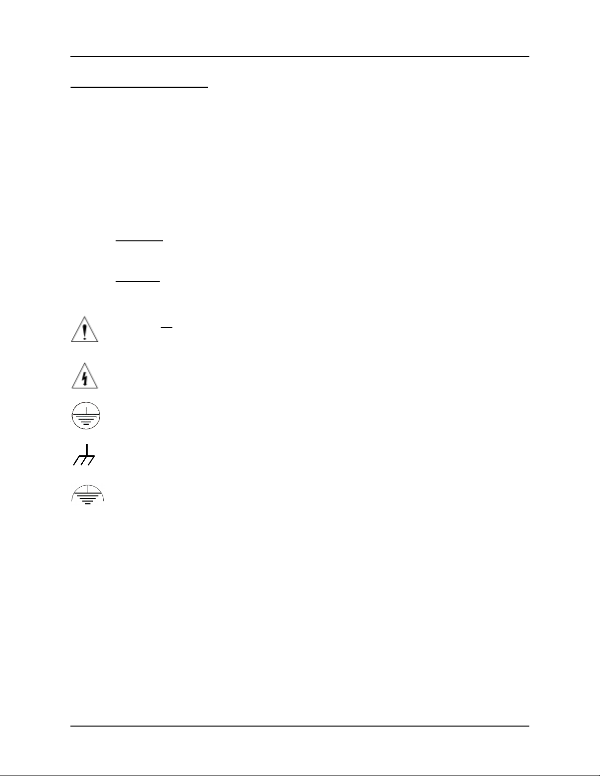
Safety Symbols
WARNING: Calls attention to a procedure, practice, or condition that could
possibly cause bodily injury or death.
CAUTION: Calls attention to a procedure, practice, or condition that could
possibly cause damage to equipment or permanent loss of data.
Refer to all manual Warning or Caution information before using this product
to avoid personal injury or equipment damage.
Hazardous voltages may be present.
Earth ground symbol.
Chassis ground symbol.
Equipotential ground symbol.
Page 3

Warranty Information
This Sigma Instruments product is warranted against defects in material and
workmanship for a period of 2 years from the date of shipment, when used in
accordance with the instructions in this manual. During the warranty period, Sigma
Instruments will, at its option, either repair or replace products that prove to be
defective.
Limitation of Warranty
Defects from, or repairs necessitated by, misuse or alteration of the product, or any
cause other than defective materials or workmanship are not covered by this warranty.
NO OTHER WARRANTIES ARE EXPRESSED OR IMPLIED, INCLUDING BUT NOT
LIMITED TO THE IMPLIED WARRANTIES OF MERCHANTABILIT Y AND FITNESS
FOR A PARTICULAR PURPOSE. UNDER NO CIRCUMSTANCES SHALL SIGMA
INSTRUMENTS BE LIABLE FOR CONS EQUENTIAL OR OTHER DAMAGES
RESULTING FROM A BREACH OF THIS LIMITED WARRANTY, OR OTHERWISE.
Return Policy
The purchaser may return this product in new condition within 30 days after shipment
for any reason. In case of return, purchaser is liable and responsible for all freight
charges in both directions.
Sigma Instruments
120 Commerce Drive, Unit 1
Fort Collins, CO 80524 USA
970-416-9660
970-416-9330 (fax)
Page 4

Table of Contents
Chapter 1 Quick Start
1.0 Introduction...................................................................................................... 1-1
1.1 Front Panel...................................................................................................... 1-1
1.2 Rear Panel.......................................................................................................1-2
1.3 System Connections........................................................................................1-3
1.4 Installation....................................................................................................... 1-4
1.5 Menus.............................................................................................................. 1-5
1.6 Thin Film Process Overview............................................................................1-7
1.7 Building a Process........................................................................................... 1-8
1.8 Depositing a Film............................................................................................. 1-11
Chapter 2 Operation
2.0 Introduction...................................................................................................... 2-1
2.1 Definitions........................................................................................................ 2-1
2.2 Defining a Film.................................................................................................2-1
2.3 Defining a Process.......................................................................................... 2-5
2.4 Sensor Setup................................................................................................... 2-7
2.5 Source Setup................................................................................................... 2-10
2.6 Running a Process..........................................................................................2-11
2.7 Loop Tuning.....................................................................................................2-15
2.8 Troubleshooting............................................................................................... 2-17
Chapter 3 Menus
3.0 Introduction...................................................................................................... 3-1
3.1 Main Menu 1.................................................................................................... 3-2
3.2 Main Menu 2.................................................................................................... 3-3
3.3 Main Menu 3.................................................................................................... 3-4
3.4 Quick Setup Menu........................................................................................... 3-5
3.5 Process Menu..................................................................................................3-7
3.6 Layer Menus.................................................................................................... 3-9
3.7 Cut/Copy Menu................................................................................................3-12
3.8 Film Menu........................................................................................................ 3-14
3.9 System Parameters Menu...............................................................................3-21
3.10 PLC I/O........................................................................................................... 3-26
Page 5

Chapter 4 Maintenance & Installation
4.0 Introduction...................................................................................................... 4-1
4.1 Cleaning.......................................................................................................... 4-1
4.2 Software Upgrades.......................................................................................... 4-2
4.3 Option Card Installation................................................................................... 4-3
4.4 Half-Rack Adapter...........................................................................................4-3
4.5 Full Rack Adapter............................................................................................ 4-4
Chapter 5 Communications
5.0 Introduction...................................................................................................... 5-1
5.1 SQC-222 Comm Program ...............................................................................5-1
5.2 Protocol........................................................................................................... 5-1
5.3 Commands......................................................................................................5-2
Appendix
A. Material Parameters
B. Specifications
C. I/O Connections
D. Handheld Remote Controller
E. Declaratio n of Conformity
Page 6

Page 7
Chapter 1 Quick Start
1.0 Introduction
The SQC-222 is a multi-channel quartz crystal monitor and deposition controller. It
measures two 1 MHz to 6 MHz quartz crystal sensors, and controls up to two
evaporation sources. Eight process control relays, and eight digital inputs are easily
configured to support a broad range of external functions, including source pocket
rotation. The number of sensors, outputs, and digital I/O can be doubled with an
optional expansion card.
This chapter will aid you in the initial setup and operation of your system . Plea se re view
the entire manual for detailed operational, programming, and safety information.
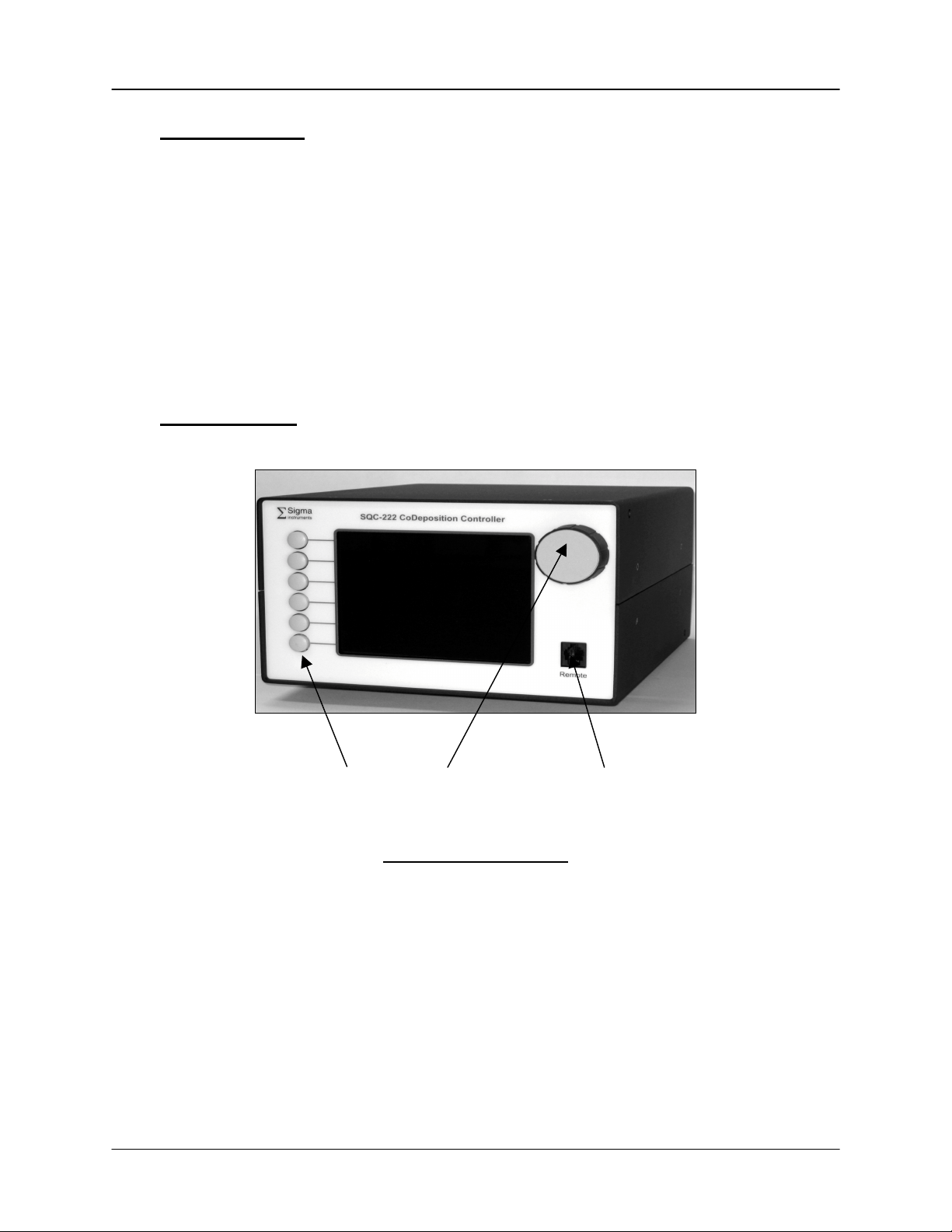
1.1 Front Panel
SoftKeys Control Knob Remote Jack
Front Panel Controls
SoftKeys Provide access to instrument operations and setup menus.
The functions of the SoftKeys change to adapt to different
operations and are displayed on the left of the screen.
Control
Knob
Remote
Jack
Used to adjust values and select menu items. Pushing the
control knob stores the current setting and moves to the next.
Connection jack for the optional handheld remote controller.
See Appendix D.
1-1
Page 8
Chapter 1 Quick Start
1.2 Rear Panel
Manufactured By
Sigma
Σ
instruments
Sensor 3 Sensor 4 Output 3 O utput 4
Sensor 1 Sensor 2 Output 1 O utput 2
SQC-222 D eposition Controller
Serial No.
I/O 9-16
I/O 1 - 8
100-120/200-240 V~
50/60 Hz
25 VA
Fuse T.5A 250V
RS-232
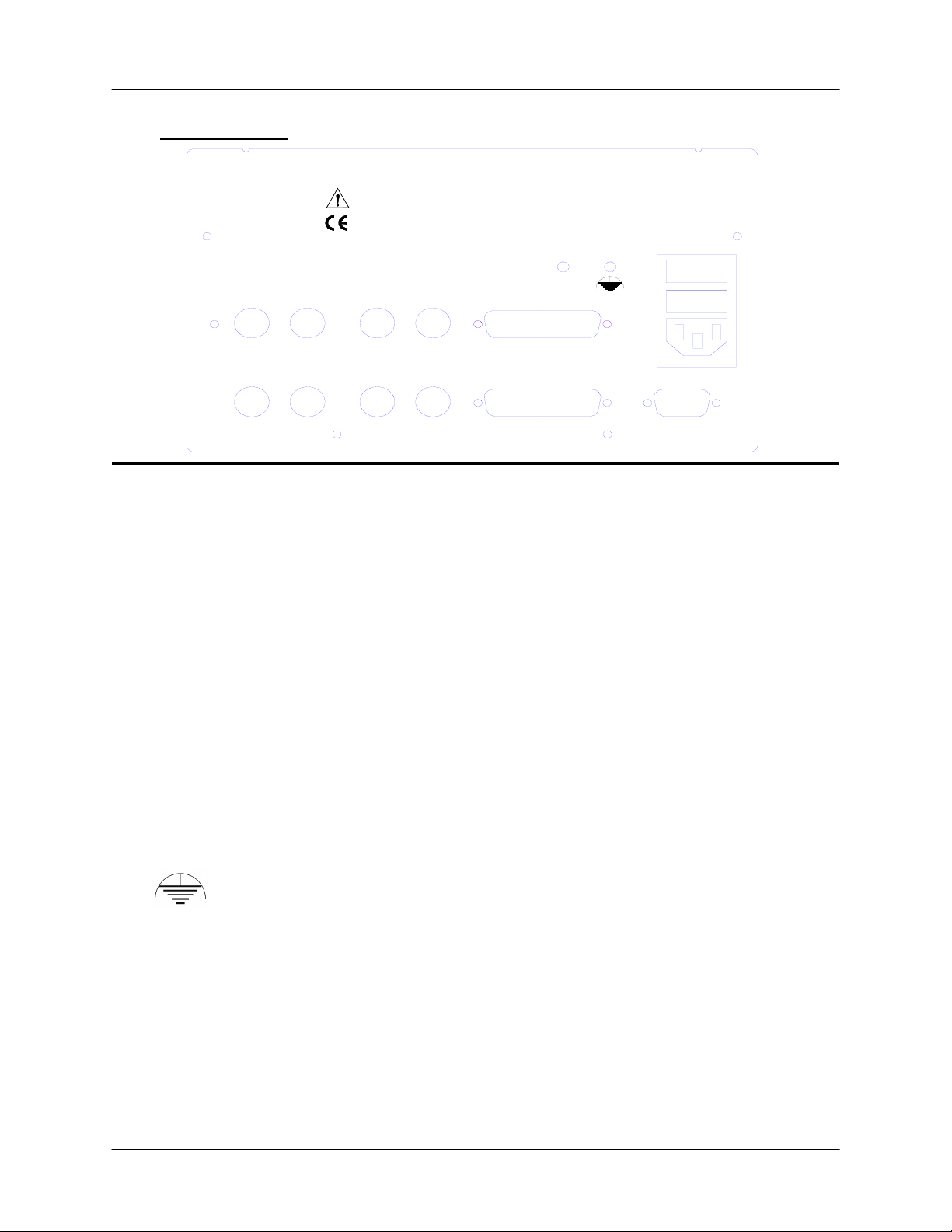
Rear Panel Connections
Sensor 1 & 2 Connects to quartz crystal sensor (see next section).
Output 1 & 2 Connects the SQC-222 output to your evaporation supply
control input (see next section).
I/O (1-8) Connects 8 relays and 8 digital inputs to external equipment for
process control. See Appendix C for connections.
RS-232 Connects to a computer for programming and data acquisition.
Also used for the PLC I/O option.
Sensor 3 & 4,
Output 3 & 4,
Increases the number of input, output, and digital I/O
connections when the optional expansion card is installed.
I/O 9-16
Measurement ground terminal useful for common system and
cable grounding.
1-2
Page 9

Chapter 1 Quick Start
Power Input and
Fuse
Connects to mains power. The SQC-222 automatically detects
mains voltages of 100-120 and 200-240VAC, 50/60 Hz
ARNING: For continued protection, replace fuses with the
W
proper type and rating.
WARNING: Use removable power cords only of the specified
type and rating, attached to a properly grounded receptacle.
1-3
Page 10
Chapter 1 Quick Start
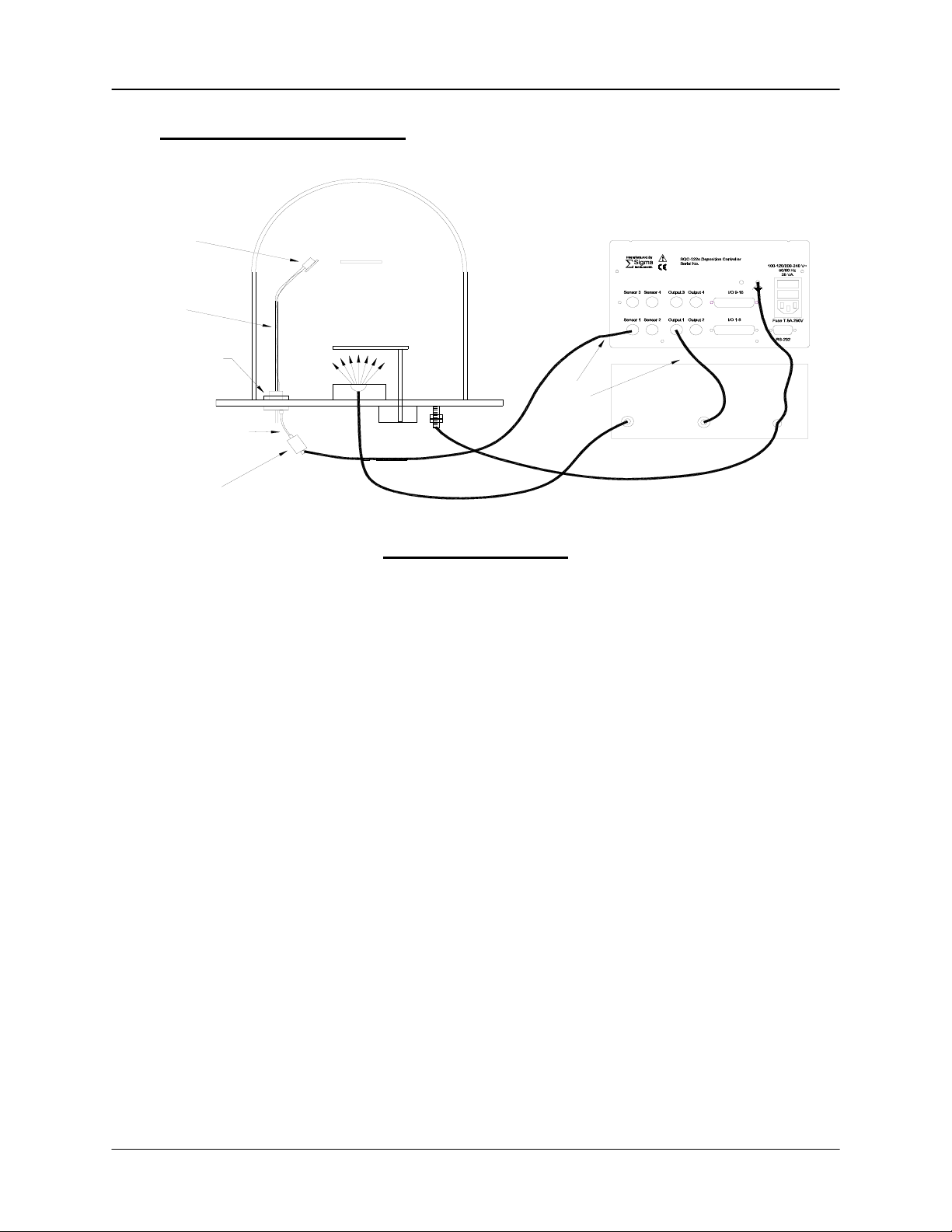
1.3 System Connections
Sensor
In-V ac
Cable
Feedthrough
Source
Shutter
Evaporation Supply
Output Control Input
6" BNC Cable
O s cillat o r
BNC
Cables
Ground Wire
System Components
Sensor Holds the quartz crystal used to measure rate and thickness.
Crystals must be replaced occasionally.
In-Vac Cable A coaxial cable that connects the sensor to the feedthrough.
Feedthrough Provides isolation between vacuum and atmosphere for
electrical and cooling lines.
6” BNC Cable Provides a flexible connection from the feedthrough to the
oscillator. Keep this cable as short as possible.
Oscillator Contains the electronics to operate the quartz crystal. Total
cable length to the crystal should be under 40”.
Sensor Input
BNC Cable
Control Output
BNC Cable
Connects the oscillator to the SQC-222 input. Lengths up to
100’ are acceptable.
Connects the SQC-222 output to the evaporation source’s
control voltage input. Keep the length below 10’.
Ground Wire A wire, typically braided, that connects the vacuum system to
the SQC-222 ground terminal. Important for noise rejection.
1-4
Page 11

Chapter 1 Quick Start
1.4 Installation
WARNING: Care should be exercised to route SQC-222 cables as far as practical from
other cables that carry high voltages or generate noise. This includes other line voltage
cables, wires to heaters that are SCR-controlled, and cables to source power supplies
that may conduct high transient currents during arc down conditions.
Rack
Installation
Power
Connection
Sensor Input
Connections
Source Output
Connections
Digital I/O
Connections
The SQC-222 occupies a 5.25” high, half-rack space. An
optional installation kit is available to adapt to a full rack (see
Chapter 4). Install the unit in a 19” rack with the supplied
hardware.
The SQC-222 automatically detects mains voltages of 100-120
and 200-240VAC, 50/60Hz .
WARNING: Verify that the power cable provided is connected to
a properly grounded mains receptacle.
Connect the BNC cables and oscillators from your vacuum
chamber feedthrough to the desired SQC-222 sensor inputs.
See the previous section for cabling details.
Connect the BNC cables from the SQC-222 output connectors
to your evaporation supply control input. Consult your Power
Supply operator’s manual for control input wiring instructions.
Refer to Appendix C for details on wiring digital I/O to the SQC222 Relay I/O connectors. Appendix C also covers I/O wiring
with the optional PLC.
Computer
Connection
If you would like to use the Windows software to collect data or
program the SQC-222, attach a 9 pin straight-thru cable from
the RS-232 connector to your computer’s serial port. A cable
is supplied with the SQC-222.
1-5
Page 12
Chapter 1 Quick Start
1.5 Menus
At power up the SQC-222 briefly displays initialization and version information, then the
Main screen.
Note: If you are prompted for a password, use the switches along the left of the screen
to enter the password. The top switch is “1”, the bottom switch is “6.” See the System
Parameters section of this manual for password setup information.
Next
Menu
Process 1 : Layer 1 of 1 Run # :0
Stopped
Power (% vs. Time)
100.0
0:00:00
Quick
Edit
Auto /
Manual
50.0
Zero
0.0
Next
Layer
Start
Out#
1
2
3
4
0.0
R a te (A /S )
0.00
0.00
0.00
0.00
6.2
12.5
Dev(%)
00.0
00.0
00.0
00.0
18.8
Thick(kA )
0.000
0.000
0.000
0.000
25.0
Pow(%)
0.0
0.0
0.0
0.0
M a in S c r ee n
The first line of the Main screen shows the name of the currently selected process.
After the process name are the layer that will run when the Start SoftKey is pushed, and
the total number of layers in the process. Further to the right is the number of times this
process has been run.
The second line of the Main screen is a status line. It displays the current phase of the
deposition cycle, and other status or error messages. When the process is running, the
right side of this line shows the process elapsed time.
Three graphs are possible: rate, rate deviation, and output power. The graphs scale the
vertical axis and scroll the horizontal axis based on the data displayed.
Below the graph are two lines that show deposition readings (four lines if the option card
is installed). This section shows current rate, rate deviation, thickness, and output
power as shown above. Alternatively it can show measured rate and thickness versus
rate and thickness setpoints.
1-6
Page 13
Chapter 1 Quick Start
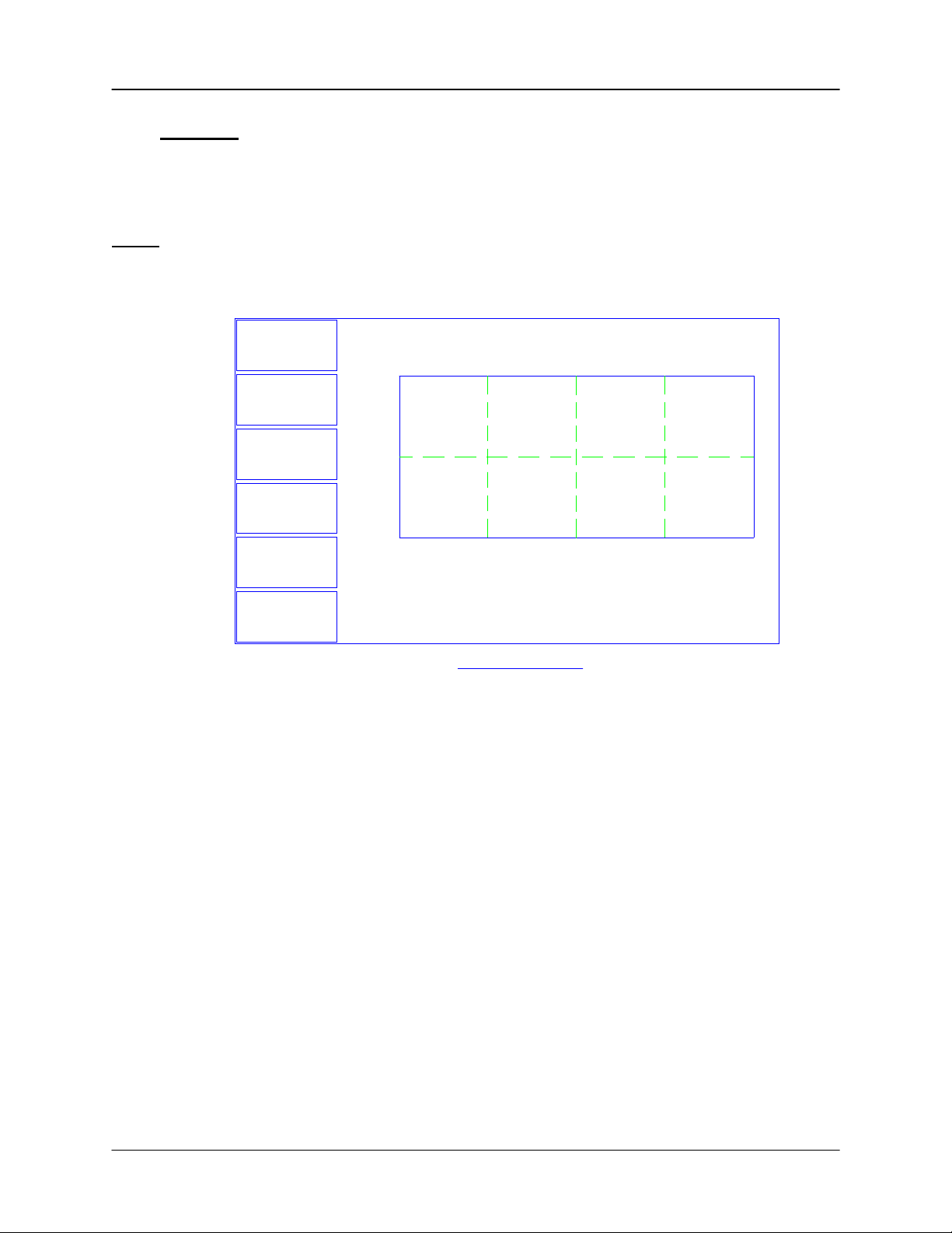
The six SoftKey legends along the left side of the screen will change, depending on the
status of the process and the functions you select. Press Next Menu to display
alternate main screen menus:
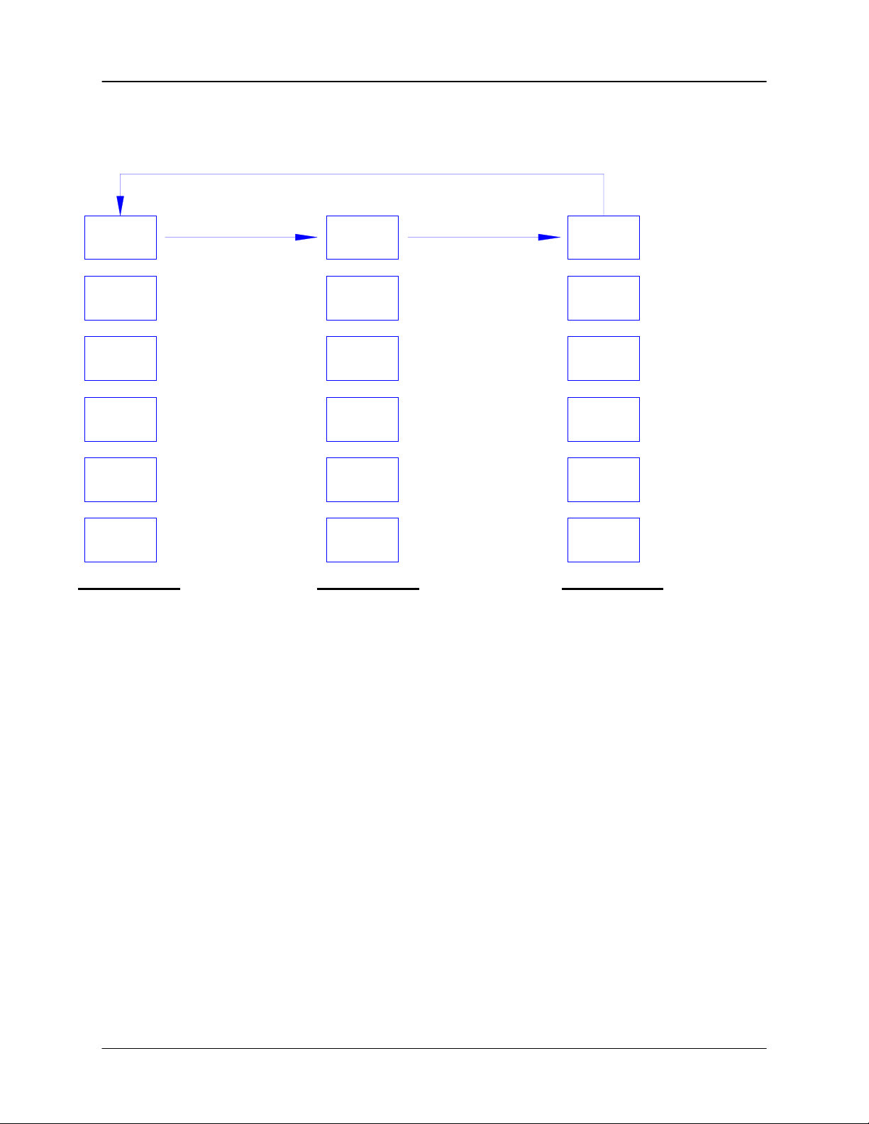
Main Menu 1 Main Menu 2 Main Menu 3
Next
Menu
Quick
Edit
Auto /
Manual
Zero
Next
Layer
Start
Selec t th e n ext la yer
Main Menu 1
Access the most
comm only edited
setting s.
Switch between PID
and Manual power
control.
Zero the thickness
reading on all
channels.
in the process.
Start or Stop the
selected layer.
Next
Menu
Next
Graph
Next
Display
Sensor
Info
Next
Layer
Start
Third menu available only
when process is stopped.
Switch graph between
Main Menu 2
rate, deviation, and
power.
Switch the readout
below the graph.
Dis p lay d eta ile d
sensor information.
Selec t th e n ext la yer
in the process.
Start or Abort the
process.
Next
Menu
Process
Menu
Film
Menu
System
Params
Start
Create or edit process
Create or edit films to
Main Menu 3
layers .
be used as layers.
Modify instrument
related se tting s.
Start the selected
layer.
Because Main Menu 3 provides access to functions that can completely redefine a
process, it is available only when the process is not running.
Spend some time now moving between the three menus. Pay particular attention to the
effects that the Main Menu 2 selections have on the displa y. W e will cover the setu p
parameters of Main Menu 3 in the Building a Process section.
1-7
Page 14
Chapter 1 Quick Start
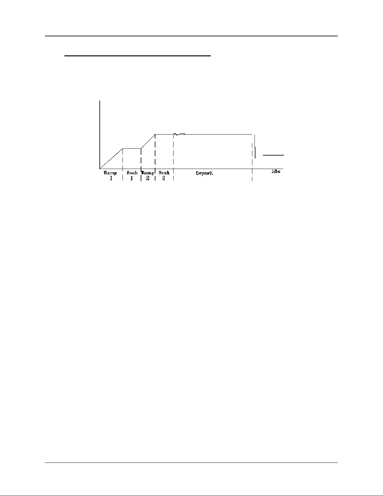
1.6 Thin Film Deposition Overview
The SQC-222 stores the recipes, and provides the operating functions, required to
control thin film deposition processes. A typical thin film deposition cycle is shown
below.
The cycle can be broken into three distinct phases:
• Pre-conditioning (ramp/soak)
• Deposition
• Post-conditioning (feed/idle)
During pre-conditioning, power is supplied in steps to prepare the evaporation source
for deposition. Once the material is near the desired deposition rate, material
deposition begins.
During deposition, the PID loop adjusts the evaporation source power as required to
maintain the desired rate. In CoDeposition multiple films can be deposited
simultaneously.
When the desired thickness is reached, the evaporation source is set to idle power. At
this point the process may be complete, or deposition of another layer may begin.
1-8
Page 15

Chapter 1 Quick Start
1.7 Building a Process
This section presents a brief guide to building and running a simple one layer process.
Chapter 2 covers instrument operation in much greater detail.
Create a
Film
M a in
Screen
Prev
Menu
Edit
Delete
A film is a material to be deposited, and its associated
deposition settings. Initially the list of films may be empty.
Press Next Menu until the Film Menu SoftKey is displayed.
Press Film Menu to view a list of stored films. Turn the setting
knob to scroll to an entry in the list that is currently labeled
<Empty>.
Press the Create SoftKey to create a default film at that
location. Note the film number that you just created. For now,
accept the default film parameters.
Press Main Screen to return to the main screen.
Process 1
S c ro ll film s w ith k n o b .
1. Film 1
2. Film 2
3. Film 3
4 . F ilm 4
5. Film 5
6. Film 6
7 . F ilm 7
8. Film 8
9. Film 9
10. Film 10
11. Film 11
12. Film 12
13. Film 13
F ilm Se le c t Me n u
Now that we are sure that at least one film exists, we will build a simple single layer
process using that film.
1-9
Page 16

Chapter 1 Quick Start
Select
Process
Edit
Process
Insert
Layer
Press the Process Menu SoftKey to view a list of processes.
Turn the setting knob to scroll to an entry in the list that is
labeled <Empty>.
Press the Create SoftKey to create a default process at that
location.
Press the Select SoftKey to make the selection the active
process.
Press the Edit SoftKey to view a list of layers in the selected
process. The layers list should be blank.
Press Insert Layer, then scroll down the list of films to the film
you just created.
Press Insert Normal to insert the selected film as Layer 1.
The display returns to the Layer Select menu.
To
Ma in
Prev
Menu
Edit
Cut /
Paste
Insert
Layer
P ro c e ss 2 5 -> L a ye r 1 -> F ilm 1
Layer
Layer1
Layer S elect Menu
F ilm
F ilm 1
A process consists of one or more layers. Each layer can have a different film, or even
multiple films (CoDeposition). For this example, we will stop with only a single layer.
1-10
Page 17

Chapter 1 Quick Start
Edit
Layer
To
Main
Prev
Menu
Edit
With Layer 1 selected, press Edit to display the Layer Edit
menu for Layer 1.
Process 1 -> Layer 1 -> Film 1
Parameter Value Units
In it R a te 1 0 .0 A /s
Fnl T hk
Tim e Setpoint
Thickness Lim it
Start M ode
Output
Max. Power 90.0
S le w R a te
Sensor 1
Sensor 2
Sensor 3
Sensor 4
Ramp1
0.100
0:00:00 h:m m:ss
0.000
Manual
Out1
90.0
On
Off
Off
Off
Disabled
Layer Edit M enu
k/A
kA
A u to /M a n .
O ut1/O u t2
%
%
O n/O ff
O n/O ff
O n/O ff
O n/O ff
En/Dis
Edit Menu
Operation
Edit
Layer 1
To edit a setting in any menu, turn the control knob to scroll to
the desired setting, then press the Edit SoftKey. The cursor
moves to the setting value, and the SoftKey functions change
to show:
Next: Store the parameter and move to next parameter for
editing.
Cancel: Stop editing and return the selected parameter to its
previous value.
Enter: Stop editing and save values for selected pa rameter.
In Edit mode, adjust the control knob to set the desired
parameter value.
Spend some time navigating through the Layer 1 parameters
and editing values. When you are comfortable, be sure your
values for Layer 1 match those shown above.
Press Main Menu to return to the Main Screen.
We have completed the design of a single layer process.
1-11
Page 18

Chapter 1 Quick Start
1.8 Depositing a Film
Note: You can simulate the steps below, without actually depositing a film, by going to
the System Params Menu and selecting Simulate Mode ON. Simulate mode is useful
for testing processes before applying power to the evaporation supply. See Section 3.6
for detailed System Parameters Menu information.
Verify Sensor
Operation
Show
Power Graph
Verify Output
Operation
Press Next Menu until the Sensor Info option is shown.
Press Sensor Info to display the quartz sensor readings.
Sensor 1 should be ON and display a % life of over 50%. If
not, check your sensor connections (Section 1.3), and refer to
Min/Max Frequency (Section 3.6).
Press Exit to return to the main screen.
Press the Next Graph SoftKey until the graph shows Power (%
vs. Time).
Press the Next Menu SoftKey until the Auto/Manual SoftKey is
displayed. Now press Auto/Manual until Manual/Auto is
displayed. Press Start to begin deposition in manual mode.
Slowly turn the control knob to increase the control voltage to
your evaporation supply. Verify that the Power(%) reading for
Output 1 (lower right, below graph) approximates the actual
output of your evaporation supply. If not, check your hookup
(Section 1.3), and refer to Scale Voltage (S ecti on 3.6) .
Caution: Observe the output power versus your evaporation
supply’s actual output. If there is a problem, press the Stop
SoftKey immediately.
Enter
Auto Mode
Please take time to review the remainder of this manual for detailed operational,
programming, and safety information.
Press the Next Menu key until the Manual/Auto SoftKey is
shown. Press Manual/Auto to change the SoftKey display to
Auto/Manual. This places the output under PID deposition
control.
Press Stop at any time to halt deposition and set output power
to zero.
1-12
Page 19

Chapter 1 Quick Start
1-13
Page 20
Chapter 2 Operation
2.0 Introduction
This chapter describes common tasks associated with operating the SQC-222. It
assumes that you understand basic operation of the menus and parameter setup as
described in Chapter 1. Detailed definitions of each parameter can be found under the
appropriate menu description in Chapter 3.
2.1 Definitions
Several terms will be used repeatedly throughout this manual. It is important that you
understand each of these terms.
Material: A physical material to be deposited. A database of approximately 100
materials is stored in the SQC-222, and additional materials may be added using the
setup software. Three parameters completely define a material: Name, Density, and ZFactor. A table of common materials, their density, and Z-Factor is listed in Appendix A.
Film: A film describes in detail how a material will be deposited. It includes the material
definition and all of the preconditioning, deposition, and post conditioning variables
necessary to accurately deposit the materi al. Bec ause th e film de fini ti on does not
include rate and thickness information, a single film can be used in several different
layers and processes. The SQC-222 stores up to 25 films.
Layer: Layers are the basic building blocks of processes. A layer consists of a film and
the thickness and rate setpoints for that stage of the process. Layers also define which
outputs and sensors will be used at that point in the process. Codeposition of multiple
films occurs when more than one output is active during a layer.
Process: A process is a sequence of layers to be deposited. The SQC-222 can store
up to 25 processes, consisting of a total of 400 layers.
Phase: A step in the deposition cycle. Preconditioning phases include Ramp 1, Soak 1,
Ramp 2, Soak 2. Deposit phases include indexer rotate, shutter delay, deposition, and
deposition rate ramps. Post conditioning phases include Feed Ramp, Feed, and Idle
Power.
2-1
Page 21

Chapter 2 Operation
2.2 Defining a Film
A film is a material to be deposited, plus all of its associated setup parameters. Keep in
mind that a film can be used in multiple layers, or even multiple processes. Editing a
film’s parameters will cause changes to every location where the film is used.
To define a film, press Next Menu until Film Menu is shown (Menu 3). Press Film
Menu. A list of 25 films (or <Empty>) will be displayed. To define a new film, scroll to
<Empty> and press Create. A new Film# is added to the list of existing films (you can
use the SQC-222 setup software later to assign descriptive film names). Press Edit to
display the parameters fo r this film.
To
Main
Prev
Menu
Edit
F ilm
Conds.
Deposit
Controls
P ro c e s s 1 Editin g : F ilm 1
Parameter Value Units
P Term 50 None
I T e rm
D Term 0.0 Sec.
F ilm T oolin g
Pocket
C rystal Qu ality
Crys t a l Stability
Xtal Fail M ode
Material
Density
Z Factor
0.7
100
None
Disabled
Disabled
Halt
Aluminum
2.73
1.08
F ilm E d it M e n u
Sec.
%
gm/cc
P Term is the proportional gain, that is the % process rate change divided by the %
input power change. The I Term (integral) sums the rate deviations over time to more
accurately achieve the rate setpoint. The D Term (derivative) speeds response to
sudden changes in rate. Volumes have been written on determining the proper PID
settings. See the section on Loop Tuning later in this chapter for a common PID loop
tuning procedure. Start with P=25, I=.5, D=0.
Film Tooling adjusts for differences in actual versus measured thickness for this film
(material). This parameter is seldom used, but can adjust for material specific
dispersion patterns. See Xtal Tooling in the System Par a meters menu for the more
commonly used tooling correction.
Pocket selects the source pocket used for this film. This parameter requires that the I/O
Setup section of the System Parameters me nu be pr og r am med for pocket rel ay s .
2-2
Page 22

Chapter 2 Operation
The next chapter covers Crystal Quality, Stability, and Fail Mode. For initial operation
leave Quality and Stability disabled, and Fail Mode set to Halt.
With Material highlighted, press Edit to scroll through the list of available materials.
Select the desired material and press Enter. You could also change the Density and ZFactor for the selected material, but it is unlikely those values are wrong. To add a new
material or edit the name of an existing material, you must use the SQC-222 setup
software.
Film conditioning adjusts the output power level to achieve a desired material state
before and after deposition. Press Film Conds to enter the film conditioning menu.
To
M a in
Prev
Menu
Edit
Process 1 Editing: Film 1
Param eter Value Un its
Ramp1 Power
Ramp1 T ime
Soak1 Time
Ramp2 Power
Ramp2 T ime
Soak2 Time
Feed Power
Ramp Time
Feed Time
Idle Powe r
Ramp Time
Film C onditioning Menu
25.0 %
0:00:10
0:00:05 h:mm:ss
50.0
0:00:05
0:00:05
0.0
0:00:00
0:00:00
0.0
0:00:00
h:mm:ss
%
h:mm:ss
h:mm:ss
%
h:mm:ss
h:mm:ss
%
h:mm:ss
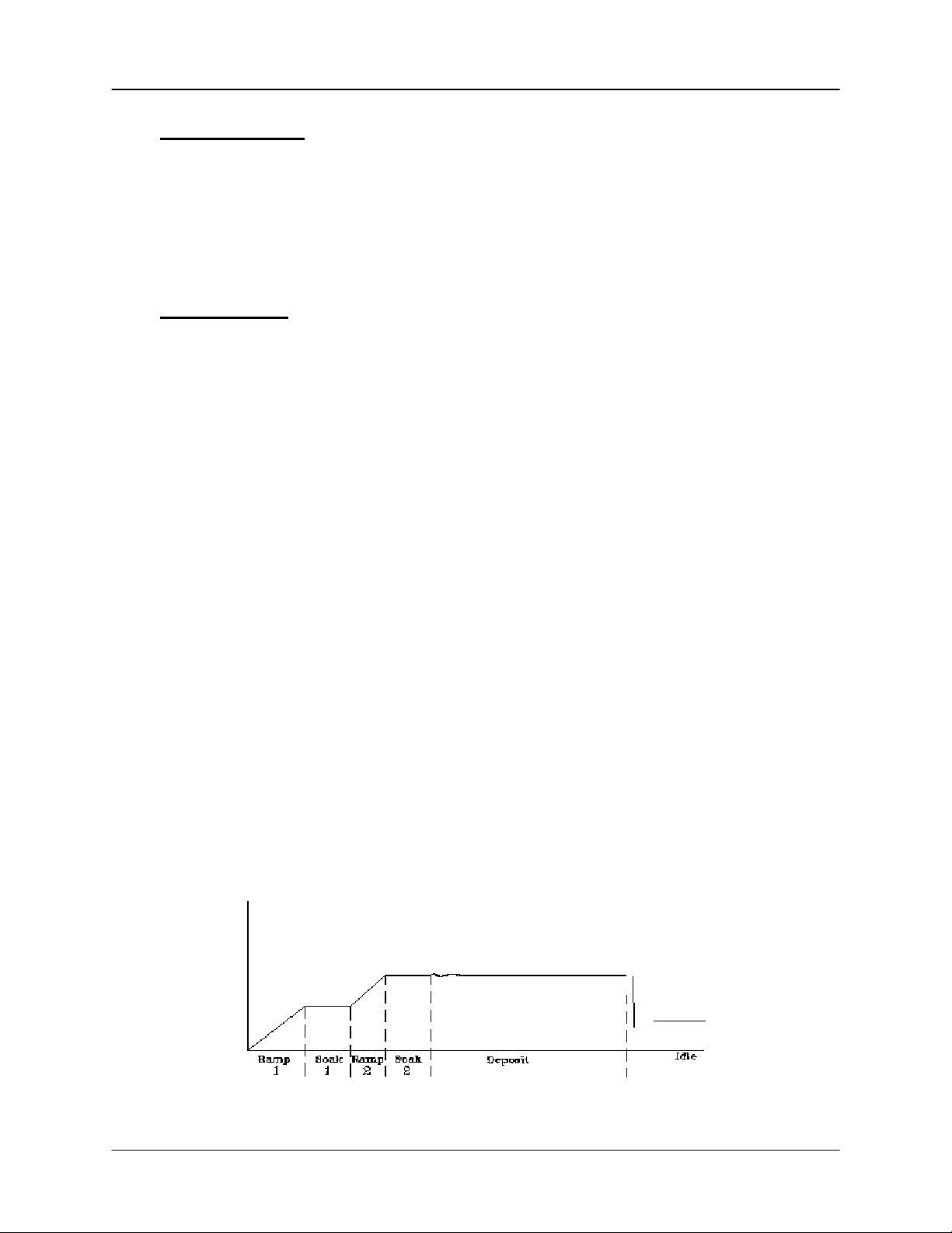
Ramp1 starts at 0% power and increases the power during Ramp1 Time to the Ramp 1
power level. Set the Ramp 1 Power and Time to gradually bring the material to a near
molten state. Set the Soak 1 Time to a value that will allow the material to
homogeneously achieve that state. Ramp 2 is used to slowly bring the material to a
power level that nearly matches the desired deposition power. Use Soak 2 to hold the
material at that level until deposition (i.e. rate control) begins.
If you use wire feed to replenish material after deposition, set the Feed Power and times
as required. The idle conditioning phase typically ramps output power back toward zero
at the end of a process.
From the Film Conds menu, press Prev Menu to return to the main Film Params menu.
2-3
Page 23

Chapter 2 Operation
Now press Deposit Controls. The Deposit Controls menu contains parameters that
modify operation during the deposition phase.
Process 1 Editing: Film 1
To
Main
Prev
Menu
Edit
Shutter delay causes the SQC-222 to delay opening the shutter until the process has
stabilized at the desired deposition rate. Capture is the % rate deviation that must be
achieved to open the shutter and go to the Deposit phase. Shutter delay is the
maximum amount of time to wait for capture to be achieved. Set Shutter Delay and
Capture to zero to disable this feature.
Parameter Value Units
Shutter Delay
Capture
Control Error
Setting
Error
Rate Sampling
Setting
0:00:00 h:mm:ss
0.0
(Ignore, Stop, Hold)
Stop
0.0
(Cont, Time, Acc based)
Continuous
Deposition Controls Menu
%
%
%
During co-deposition, the SQC-222 waits for all films to achieve capture before moving
to the deposit phase. If any film fails to achieve rate capture within its programmed
shutter delay time, an error occurs.
If the SQC-222 is unable to maintain the desired deposition rate (for example, out of
material or a bad sensor), one of three actions is possible. Keep trying (Ignore), set
power to zero to halt deposition (Stop), or maintain constant power (Hold) and
extrapolate thickness from the last good rate reading. Until your process is known and
stable, it is best to leave the Control Error setting on Ignore.
Rate sampling can extend sensor life in high rate processes. Select Cont (continuous)
to disable rate sampling. A Time selection closes the shutter for a fixed time, then
opens the shutter for a fixed time to sample the rate. Acc Based (accuracy based)
sampling closes the shutter for a fixed time, then opens the shutter until the desired rate
is achieved. Rate Sampling assumes a very stable process!
2-4
Page 24

Chapter 2 Operation
2.3 Defining a Process
To define a process, press Next Menu until the Process Menu SoftKey is shown. Press
Process Menu. A list of 25 processes (or <Empty>) will be displayed. To define a new
process, scroll to <Empty> and press Create. A new Process# is added to the list of
existing processes (use the SQC-222 setup software to assign descriptive process
names).
Press Select, then Edit to display the sequence of layers and films that comprise the
selected process.
To add a layer, scroll to the desired location in the layer sequence, and press Insert
Layer. Select a film from the list and press Insert Normal to insert a new layer. Layers
are always inserted at the selected layer. The selected layer and subsequent layers will
be shifted down.
Hint: When building a process it may be easiest to add a “dummy” last layer and keep
inserting above that layer. When the process is complete, delete the “dummy” layer.
To add a film to an existing layer so that materials will be codeposited, highligh t the
layer after the desired codeposition layer. Press Insert Layer, select the desired film,
then press Insert CoDep. The codeposited film will be inserted in the layer above the
selected layer, and indented to show that it is a codeposition film.
The display below shows two films being codeposited with Film1, then a fourth film
being deposited as an additional layer. While layers are always numbered sequentially,
the films are sequential only for this example. Any film can be used in any layer.
To
Ma in
Prev
Menu
Edit
Cut /
Paste
Insert
Layer
P ro c e ss 2 5 -> L a ye r 1 -> F ilm 1
Layer
Layer1
L a y e r2
L a y e r3
Layer4
F ilm
F ilm 1
F ilm 2
F ilm 3
F ilm 4
Layer S elect M enu
2-5
Page 25

Chapter 2 Operation
To delete a layer, highlight it in the Layer Select menu and press Cut/Paste.
On the Cut/Paste menu, press Cut to remove the layer. Press Prev Menu to return to
the Layer Select menu.
To
Main
Prev
Menu
Copy
Cut
P ro c e ss 2 5 -> L a ye r 1 -> F ilm 1
Layer
Layer1
L a y e r2
L a y e r3
Layer4
Cu t/Paste Menu
F ilm
F ilm 1
F ilm 2
F ilm 3
F ilm 4
To move or duplicate a layer, highlight it in the Layer Select menu and press Cut/Paste.
On the Cut/Paste menu, press Cut to remove the layer. A copy of the layer is
automatically saved to copy/paste memory. Press Copy to save a copy to memory
without removing the layer. Without leaving the Cut/Past menu, highlight the layer that
you want to insert the cut layer above and press Paste Normal or Paste CoDep.
Operations on the Cut/Past menu can be repeated several times. Each cut operation
overwrites the cut/paste memory. Pressing Prev Menu on the Cut/Past menu returns to
the Layer Select menu. The contents of copy/paste memory are lost!
Note: Once a film is assigned to a process layer, you cannot change the film. Instead,
cut the layer, then insert a new layer and select the desired film.
2-6
Page 26

Chapter 2 Operation
2.4 Defining a Layer
To edit a Process Layer, press Process Menu. Select the desired process, then press
Edit. Finally, select the desired layer and press Edit.
To
Main
Prev
Menu
Edit
Process 1 -> Layer 1 -> Film 1
Parameter Value Units
In it R a te 1 0 .0 A /s
Fnl Thk
Tim e Setpoint
Thickness Lim it
Start Mode
Output
Max. Power 90.0
S le w R a te
Sensor 1
Sensor 2
Sensor 3
Sensor 4
Ramp1
0.100
0:00:00 h:mm :ss
0.000
Manual
Out1
90.0
On
Off
Off
Off
Disabled
k/A
kA
A u to /M a n .
O ut1/O u t2
%
%
O n/O ff
O n/O ff
O n/O ff
O n/O ff
En/Dis
Layer Edit M enu
Initial Rate and Final Thickness are the main process setpoints for the film used in this
layer. Time Setpoint and Thickness Limit are secondary values that will activate a rela y
when they are reached.
Start Mode controls operation in multi layer processes. In Auto Start the layer starts
immediately on completion of the previous layer. Manual Start waits for a user signal
via the front panel, RS-232, or digital input to start the layer. Don’t confuse this Manual
Start mode with the Manual Power SoftKey function.
The Output entry assigns the layer/film parameters to a specific SQC-222 rear panel
output. The layer and film parameters for power, preconditioning, PID settings, etc. will
be applied to the selected output. Assign the Max Power and Slew Rate appropriate for
this material and your power supply. For now, set both to 100%. Set them to lower
values if you find that small power changes cause excessively large changes in
deposition rate.
The SQC-222 can use multiple sensors to measure a film’s deposition rate and
thickness. If multiple sensors are selected, an average of the sensors is used. Set
each sensor that will be used to measure this film to ON.
Rate Ramps allow the PID controlled deposition rate to change over time, under PID
control. Each rate ramp has a starting thickness, an elapsed time to ramp to the new
rate, and a new rate setpoint. Each process layer can have up to two rate ramps.
2-7
Page 27

Chapter 2 Operation
2.5 Sensor Setup
Sensor setup involves selecting the sensor(s) to be used, setting the Min/Max crystal
frequencies, and adjusting the Tooling Factor.
In the System Params menu, Max Frequency is the initial frequency of a new crystal,
typically 6.0e+06 Hz (6 MHz). Due to manufacturing tolerances, some crystals may
oscillate above 6MHz initially, which would be detected a s a senso r error. S etting the
Max Frequency slightly above the nominal value, to say 6.1 MHz will avoid this problem.
Min Frequency is the frequency where the SQC-222 will flag a sensor as bad. For a
6 MHz crystal, the Min Frequency is typically 5 MHz. Crystal failure is often predicted
by periods of “mode hopping,” where the crystal briefly makes an abrupt change in
frequency, or stops oscillating altogether. Some materials will cause crystals to fail or
mode hop well before 5 MHz. It is good practice to set the Min Frequency to a value
that indicates crystal failure in you process well before crystals actually fail.
To better determine impending crystal failure, Crystal Quality and Stability parameters
are also available for each Film. See Chapter 3, Film Menus, for more information on
setting Crystal Quality and Stability.
Sensor Tooling and System Tooling (System Params menu) adjusts for the difference
in measured deposition rate between the sensor and the substrate being coated.
Substrate
Substrate
Tooling
Over 100%
In the left illustration above, the sensor will measure less rate o r thickness than is
actually deposited on the substrate because of its positio ning. In the right illustration,
the sensor will measure high. Tooling is the ratio of the actual substrate deposition rate
or thickness, to that measured by the sensor.
Tooling
Under 100%
Let’s assume that at the end of deposition the sensor measures a thickness of 1.000
kA. But, suppose the actual substrate is deposited to 1.100 kA thickness (as
2-8
Page 28

Chapter 2 Operation
determined by some other means, such as a stylus profilometer). Then the tooling for
this sensor would be:
(1.100 / 1.000) x 100 = 110
A simple rule to remember is: If the rate/thickness reading is low, then increase the
tooling value. If the rate/thickness reading is high, then lower the tooling value.
Xtal Tool 1 and 2 adjust the tooling for each individual sensor. It is particularly important
when using sensor averaging to balance multiple sensors so that their measurements
match. System Tooling applies to the overall Rate and Thickness measurements of all
sensors. It is sometimes used to adjust for some systematic difference in the actual vs.
measured readings. In general, Crystal Tooling (Xtal Tool 1 and 2) should be used
instead.
Multi Xtal Count sets the number of crystals in a multi-crystal sensor head. For a
standard single or dual sensor head, leave the value at 0.
Once the sensor parameters are set, test your sensor setup to assure reliable readings
at the SQC-222. Press Next Menu until the Sensor Info option is shown, then press
Sensor Info.
Any connected sensor (whether programmed On or Off) should display its frequency
and % remaining life, as defined by Min and Max Frequency setup. For a new sensor,
the value should be near 100%. If the % Life is 0.00% or jumps around, check your
cabling and the installation of the sensor in its holder.
Sigma supplies a small 5.5 MHz “test crystal adapter” with each oscillator. If the % Life
reading is not correct, remove the 6” BNC that is connected to your feedthrough at the
oscillator. Connect the test crystal and adapter to the oscillator connector labeled
Feedthrough. For a typical setup of 6 MHz Max Frequency and 5 MHz Min Frequency,
the % Life display should be near 50%.
Sensors are assigned to each Layer, as described in the Chapter 3, Layer Edit.
More information on locating system and sensor problems is described in the
Troubleshooting section, later in this chapter.
2-9
Page 29

Chapter 2 Operation
2.6 Source Setup
The SQC-222 controls deposition rate by varying the control voltage to an external
evaporation (source) supply.
The SQC-222 output voltage range is set in the Systems Params menu. For the
supply connected to each output, set the Scale to the control voltage that corresponds
to 100% output on the source supply. The SQC-222 uses 0 volts as 0% output, and the
programmed value as 100% output. Scale values from –10 volts to 10 volts are
possible.
If you find that very small changes in control voltage yield large changes in deposition
rate, you can lower the Scale value to decrease the dynamic range. Also, each Film
has a Max Power and Slew Rate parameter that may be used to customize response to
that film.
2-10
Page 30

Chapter 2 Operation
2.7 Running a Process
Once a Process is defined with the desired Layers, and the sensors and source supply
are properly connected, the deposition process is ready to run. This section describes
the steps to select, start, and stop a process.
There are three Main Menu screens while the process is stopped (two when it is
running). Pressing the Next Menu SoftKey accesses the three screens. Next Menu is
the first SoftKey in each of the three menus. Likewise, Start/Stop is the last SoftKey on
each Main Menu. Main Menu 1 displays the SoftKeys used to control the process.
Next
Menu
Process 1 : Layer 1 of 1 Run # :0
Stopped
Power (% vs. Tim e)
100.0
0:00:00
Quick
Edit
Auto /
Manual
50.0
Zero
0.0
Next
Layer
Start
Out#
1
2
3
4
0.0
R a te (A /S )
0.00
0.00
0.00
0.00
6.2
12.5
Dev(%)
00.0
00.0
00.0
00.0
18.8
Thick(kA)
0.000
0.000
0.000
0.000
25.0
Pow(%)
0.0
0.0
0.0
0.0
M a in S c re e n
The Quick Edit SoftKey (available while the process is running) provides easy access
to the most commonly set process parameters.
To
Main
Edit
Next
Layer
Process 1 --> Layer 1 --> Film 1
Parameter Value Units
Init Rate 0.2 A/s
Fnl Thk
P Term 70 None
I Term
D Term
Max. Powe r
Slew Rate
Material
Density
Zfactor 1.00
3.0
0.1
0.0
99.0
99.0
Aluminum
2.73
kA
Sec.
Sec.
%
%
gm/cm^2
Quick Edit Menu
Press Next Layer and Prev Layer on the Quick Edit screen to review each layer.
Press To Main to return to the Main screen.
2-11
Page 31

Chapter 2 Operation
Next
Menu
Process 1 : Layer 1 of 1 Run # :0
Stopped
Power (% vs. Time)
100.0
0:00:00
Quick
Edit
Auto /
Manual
50.0
Zero
0.0
Next
Layer
Start
Out#
1
2
3
4
0.0
R a te (A /S )
0.00
0.00
0.00
0.00
6.2
12.5
Dev(%)
00.0
00.0
00.0
00.0
18.8
Thick(kA )
0.000
0.000
0.000
0.000
25.0
Pow(%)
0.0
0.0
0.0
0.0
M a in S c r ee n
The Auto/Manual key alternates between Automatic (PID) output control and Manual
(user) output control. In Manual mode, the SQC-222 immediately starts the deposition
phase for the current layer, whether the process was stopped or running. However, the
PID loop is disabled and the front panel control knob controls output power.
In Manual Mode, you will usually display the Rate Graph, an d manually adjust the
output power to achieve the desired deposition rate. It is easy to exceed a layer’s Final
Thickness in Manual mode, so watch the Thickness reading carefully. Manual mode is
particularly useful for determining preconditioning power levels, and loop tuning.
Moving from Manual mode to Auto mode places the SQC-222 into automatic (PID)
control. The PID control loop will try to achieve ra te setpoint, so there may be a rapid
change in output power.
Note: Don’t confuse the Manual/Auto power SoftKey with a layer’s Manual and Auto
Start. Manual/Auto Start modes are a Layer setup parameter that tells the SQC-222 to
wait for operator intervention before starting a Layer.
The Zero SoftKey can be used to zero the thickness reading at any time. It is not
normally needed, since the SQC-222 automatically zeroes the thickness at the
beginning of each layer. However, it is useful when simulating a process, and when
operating in Manual mode.
Next Layer moves the starting point for the Start SoftKey to the next layer, wrapping
back layer 1 at the end of the process.
The last SoftKey on this menu is used to Start and Stop the deposition cycle. Press
Start to start the layer shown on the first line of the screen at the preconditioning phase.
2-12
Page 32

Chapter 2 Operation
Press Stop to halt the current layer. You can restart the current layer pressing Start.
Press Next Layer, then Start, to start any other process layer.
Note: It is best (and safest!) to place the SQC-222 in Simulate mode when a process is
first run. If the bottom SoftKey does not show Start Simulate, press System Params
and turn Simulate Mode ON.
Enough preliminaries, let’s start the process!
Press Start to start deposition. If the first layer Start mode was programmed as
Manual, you will need to press the Start Layer SoftKey now to start the layer.
Next
Menu
Process 1 : Layer 1 of 1 Run # :1
Soak 2
Power ( % vs. Time)
100.0
0:25:00
Quick
Edit
Auto /
Manual
50.0
Zero
0.0
Start
Layer
Start
Out#
1
2
3
4
0.0
Rate(A/S)
1.20
0.00
0.00
0.00
6.2
12.5
Dev( %)
00.0
00.0
00.0
00.0
18.8
Thick(kA)
0.085
0.000
0.000
0.000
25.0
Pow( %)
75.0
0.0
0.0
0.0
Preconditioning
The process starts with the first layer preconditioning phase. When preconditioning is
complete, the deposition phase begins. The deposition phase ends when Final
Thickness is reached for the layer, then Feed and Idle phases run (if programmed).
If the second layer is Auto Start, its cycle begins immediately when the first layer is
complete. If the second Layer is Manual Start, or it’s the last layer in the process, the
process halts and waits for operator intervention.
2-13
Page 33

Chapter 2 Operation
While the process is running, a Stop Layer SoftKey is shown (see above). Pressing
Stop Layer temporarily halts the current Layer.
Next
Menu
Process 1 : Layer 1 of 1 Run # :1
Layer Stopped
R a t e (A/s v s . T im e )
10.0
0:42:00
Quick
Edit
Auto /
Manual
5.0
Zero
0.0
Next
Layer
Start
Out#
1
2
3
4
0.0
R a te (A /S )
4.91
0.00
0.00
0.00
6.2
12.5
Dev(%)
- 1.8
00.0
00.0
00.0
18.8
Thick(kA )
0.095
0.000
0.000
0.000
25.0
Pow(%)
75.0
0.0
0.0
0.0
Layer Stopped
Start repeats the stopped layer, beginning with preconditioning. Next Layer allows you
to select another layer to start.
Note: Pressing the Abort SoftKey on Main Menu 2 at any time completely aborts the
process.
Spend some time in Simulate mode verifying that the process sequences through each
phase of each layer as expected. If not, use the Quick Setup, Process, and Film menus
to make corrections.
Because the process is being “simulated,” some parameters will not be correct for your
process (particularly PID). However, you can become familiar with the effect of each
parameter in this simulated process. Also practice using the Next Menu options,
especially Auto/Manual modes.
Once you have verified the process in Simulate Mode, you may return to the System
Params menu and turn Simulate OFF to start testing your process. Use the next
section to finalize the loop PID settings.
2-14
Page 34

Chapter 2 Operation
2.8 Loop Tuning
This section will help you adjust your control loop PID parameters to achieve a stable
deposition process. Keep in mind that there is no “best” way to determine PID
parameters, and no one set of settings that are best.
Set System Parameters: Be sure that the output Scale and crystal Min/Max Frequency
parameters are accurate for your system. All Tooling parameters are best set to 100%
for now. A Period of .25 seconds is also a good starting point. Simulate should be
OFF.
Create a One-Layer Test Process: Create a new film with all default values. Create a
new process that has the new film as its only layer, and select it as the current process.
In the Quick Setup menu set Init Rate to your desired rate and Final Thickness to a
large value, say 10X your desired Final Thickness. Select the proper Sensor(s), Output,
and Material. Set Max Power to 100% and Slew Rate to 100%.
Test the Setup: Press Auto/Manual to start the layer in Manual mode. Slowly turn the
control knob to a power of 10%, and verify that your power supply output is about 10%
of full scale. Continue to turn the control knob until a Rate(A/s) above 0 is shown.
Again, verify that the power supply output agrees with the SQC-222 Power(%) reading.
If the readings don’t agree, check your wiring and process setup. In particular, verify
that the System Parameters output scale agrees with your power supply input
specifications.
Determine Open Loop Gain: Slowly adjust the control knob until the Rate(A/s) reading
approximately matches your desired rate (Init Rate in the Quick Setup menu). Record
the desired rate Power(%) reading as PWRDR. Slowly lower the power until the
Rate(A/s) reading is just at (or near) zero. Record the zero rate Power(%) reading as
PWR0R.
Determine Open Loop Response Time: Calculate 1/3 of your desired rate (RATE
and 2/3 of the desired rate (RATE
Rate(A/s) matches RATE
. Get ready to record the loop’s response to an input
1/3
change. Quickly adjust Power(%) to PWR
reading to reach RATE
. You may want to do this several times to get an average
2/3
) for this layer. Slowly increase the power until
2/3
. Measure the time for the Rate (A/s)
DR
1/3
),
response time reading. Displaying the Rate graph will also help. Twice the measured
time is the step response time, TIMESR. TIMESR is typically .7 to 1.5 seconds for EBeam evaporation, 5 to 20 seconds for ther mal ev ap or ation.
Return the output power to 0%, then press Manual/Auto to return to Auto mode. Follow
these steps to set the loop PID parameters:
Set PID Values: In the Quick Setup menu set P=25, I= TIME
, D=0. Exit the Quick
SR
Setup menu. Press Start and observe the Power graph. The power should rise from
0%, and stabilize near PWRDR with little ringing or overshoot. If there is more than
2-15
Page 35

Chapter 2 Operation
about 10% overshoot, lower the P Term. If the time to reach PWRDR is very slow,
increase the P Term. A lower I Term will increase response time, a higher value will
eliminate ringing and setpoint deviations. It is unlikely you will need any D Term.
Continue to Start the process and adjust PID until steady-state response is smooth and
the step response is reasonably controlled. You don’t need to totally eliminate ringing
during the step if the steady-state response is smooth, preconditioning will minimize
step changes.
Set Preconditioning: The power level you recorded as PWR0R is the power where
deposition just begins. That’s a good value for Ramp 1 power in the Film Conds menu.
PWRDR, or slightly less, is a good value for Ramp 2 Power. This will eliminate a large
step change when entering the deposition phase.
Once PID terms are established for a material, they will typically be similar for other
materials. Only the P Term and preconditioning power levels may need adjustment.
2-16
Page 36

Chapter 2 Operation
2.9 Troubleshooting
Most SQC-222 problems are caused by defective crystals or improper film setup,
particularly incorrect PID settings for the control loop. Follow the procedures below to
identify and correct common problems.
2.9.1 No Readings, or Erratic Readings from Sensors:
Disconnect the deposition source supply. This eliminates the possibility that a noisy
source, or poor loop tuning, are causing an unstable PID loop.
Verify that the sensors, oscillator and cab ling are connected as shown in Section 1.5.
Assure that a good ground connection has been made to the SQC-222 chassis.
Replace the quartz crystal. Crystals sometimes fail unexpectedly, or exhibit erratic
frequency shifts before total failure. Depending on the material, crystals may fail well
before the typical 5 MHz value. If you find that crystals consistently fail early, you may
want to set Min Frequency in the System Menu to a value higher then 5 MHz.
In the System Menu, assure that Simulate Mode is OFF, and Frequency Min/Max are
set properly for your crystals (typically Freq Min=5.0 MHz, Freq Max=6.0 MHz). Some
manufacturer's crystals exceed 6MHz when new. Setting Frequency Max to 6.1 MHz
will correct that problem, with no bearing on instrument accuracy.
Press Film Menu, Edit, and assure that the proper sensors are enabled. Press Exit to
Main, then Next Menu until the Sensor Info SoftKey shows. Press Sensor Info to show
sensor Frequency and % Life.
While not depositing, observe the % Life display for each active sensor. The value
should be stable, between 20% and 100%.
If the % Life reading is zero or unstable: Recheck the wiring from the sensor to the
SQC-222, and verify that the SQC-222 is properly grounded. Also check that the
crystal is seated properly in the sensor head.
Swap the sensor to the other SQC-222 input. If both SQC-222 inputs show zero or
unstable readings, the problem is almost certainly a wiring or sensor problem.
If the % Life is less than 50%: Replace the crystal and assure that % Life is near
100%, very stable. If % Life is not near 100%, check the Frequency Min/Max limits.
If the problem is not corrected: Referring to Section 1.5, disconnect the 6” M/F BNC
cable from the external oscillator module. A 5.5 MHz test crystal and BNC barrel
adapter is supplied with each oscillator. Attach the test crystal to the oscillator
Sensor connector. The display should read about 5.5 MHz, very stable. If not,
contact Sigma Instruments technical support.
2-17
Page 37

Chapter 2 Operation
When the frequency reading is stable, reconnect the source supply. Start the
deposition process in Manual mode with 0% power. The % Life readings should remain
stable.
Slowly raise the % Power until a rate reading is displayed above the graph. As material
is deposited on the crystal, the % Life reading should remain stable, or drop slowly and
consistently. If not, check your source supply for erratic output. Also assure that the
sensor is not too close to the source (particularly in sputtering).
2.9.2 Incorrect Rate or Thickness Measurement:
First, complete the procedures in Section 2.9.1 to assure reliable sensor operation.
Set the Xtal Tooling as described in the System Menu section of Chapter 3. Incorrect
Xtal Tooling values will cause consistently low or high rate/thickness values for every
material.
Once the Xtal Tooling is set, set Film Tooling in the Film Menu to 100% unless you are
certain that another value is needed for a specific film.
Verify that the Density and Z-Factor values match those in the Materials Parameters
Appendix. If the material is not listed, check a materials handbook. Density has a
significant effect on rate/thickness calculations.
Z-Factor corrects for stresses as a crystal is coated. If readings are initially accurate,
but deteriorate as crystal life drops below 60-70%, you need to adjust the Z-Factor or
replace crystals more frequently. The relationship between Z-Factor and Acoustic
Impedance is discussed in the Materials Appendix.
2.9.3 Poor Rate Stability:
First, be sure that a stable rate can be achieved in Manual mode, as explained in
Section 2.9.1. Once a stable rate is achieved in Manual mode, follow the Loop Tuning
procedures of Section 2.8.
2-18
Page 38

Chapter 2 Operation
2-19
Page 39

Chapter 3 Menus
3.0 Introduction
Three menus on the Main Screen control SQC-222 operation. The SoftKeys associated
with each of these menus leads to sub menus. This chapter describes the function of
each setting in each menu. It is arranged by Main Screen menus, then by major sub
menus.
The power-up screen for the SQC-222 is shown below.
Next
Menu
Process 1 : Layer 1 of 1 Run # :0
Stopped
Power (% vs. Time)
100.0
0:00:00
Quick
Edit
Process
Menu
50.0
Film
Menu
0.0
System
Params
Start
Out#
1
2
3
4
0.0
R a te (A /S )
0.00
0.00
0.00
0.00
6.2
12.5
Dev(%)
00.0
00.0
00.0
00.0
18.8
Thick(kA )
0.000
0.000
0.000
0.000
25.0
Pow(%)
0.0
0.0
0.0
0.0
M a in S c re e n
At the top of the screen you will find informa tion about the current process, layer, and
run status. Immediately below is the current deposition phase and error conditions.
The central graph displays either Rate, Rate Deviation, or Output Power. If multiple
materials are being deposited, the graph shows each material in a different color.
Below the graph is a display of deposition readings. This display always shows the
current rate and thickness readings. The remaining columns can be set to display
either Power and Deviation readings or Rate and Thickness setpoints. For a standard
SQC-222 there will be two lines, corresponding to the two control outputs. With an
expansion card installed there will be four lines, as shown.
The Main Screen SoftKey legends will change based on the Menu selection and the
current process status. The three different menus for the main screen are accessed by
press Next Menu SoftKey.
3-1
Page 40

Chapter 3 Menus
3.1 Main Screen, Menu 1
The table below describes the function of each SoftKey on Main Screen, Menu 1.
Next
Menu
Quick
Edit
Auto / Manual
Zero Zeros the thickness reading. Useful for resetting or extending
Next
Layer
Start
Layer
Sequences through each of the three Main Screen menus.
Displays the Quick Setup Menu of commonly changed process
values. If this key is not visible, the active process has no
layers defined.
Toggles between Auto and Manual power control. When
Auto/Manual is shown, output power is set by the SQC-222 to
achieve the programmed deposition rate. When Manual/Auto
is shown, the control knob sets the output power.
the current deposition layer.
Sequences through each process layer. Use this key to start
or restart the process at any layer. Only visible when the
process is stopped.
Each layer in a process can be defined as Auto Start or Manual
Start. Auto Start layers begin immediately on completion of the
previous layer. Manual start layers wait for the operator to
press Start Layer. Only visible when waiting to start a Manual
Start layer.
Start/Stop Starts or halts the current process. Sets all outputs to zero.
3-2
Page 41

Chapter 3 Menus
3.2 Main Screen, Menu 2
The table below describes the function of each SoftKey on Main Screen, Menu 2.
Next
Sequences through each of the three Main Screen menus.
Menu
Next
Graph
Sequences through the graph options for the Main Screen.
Choose between Rate, Rate Deviation, and Power graphs.
The Y axis of the Rate Deviation graph can be scaled in the
System Params menu. A fourth “graph” screen displays rate,
thickness, and power in large text format for easy viewing.
Next
Displays
Toggles between data display options at the bottom of the
Main Screen. The first display option shows Rate, Rate
Deviation, Thickness, and Power readings. The second option
shows Rate measurements in the first column; Rate setpoints
in the second column. Thickness measurements are shown in
the third column, then Thickness setpoints in the fourth.
Sensor Info Replaces the Main Screen with the Sensor screen.
Sensor #
Exit
Enable
Freq
Life
Sensor Info
Next
Layer
Start Layer
Sequences through each process layer. Use this key to start
or restart the process at any layer.
Each layer in a process can be defined as Auto Start or Manual
Start. Auto Start layers begin immediately on completion of the
previous layer. Manual start layers wait for the operator to
press Start Layer. Only visible when waiting to Manual Start.
Start/Stop Starts or halts the current process. Sets all outputs to zero.
3-3
Page 42

Chapter 3 Menus
3.3 Main Screen, Menu 3
Menu 3 is can accessed only while the process is stopped. This menu gives access to
process, film, and system setup parameters that cannot be altered while a process is
running.
To change these parameters when a process is running: Stop the process; modify the
parameters; then restart the process at the desired layer.
The table below describes the function of each SoftKey on Main Screen Menu 3.
Next
Menu
Process
Menu
Film
Menu
System
Params
The remainder of this chapter provides a detailed explanation of each sub menu and its
settings.
Sequences through each of the three Main Screen menus.
A process is a sequence of layers of deposited film(s). The
Process Menu selection allows you to build and edit the
sequence of process layers.
A film is basically a material plus the setup information
necessary to deposit that material. Settings on the Film Menu
include pre/post conditioning, deposition error controls, and the
physical chamber setup for that material.
System parameters control the overall operation of the SQC-
222. Tooling, crystal frequency, and operating modes are
examples of settings found on the System Para me ter s Men u.
3-4
Page 43

Chapter 3 Menus
3.4 Quick Setup Menu
The Quick Setup Menu provides access to the most commonly adjusted parameters for
the current process and layer.
Process 1 --> Layer 1 --> Film 1
Parameter Value Units
Init R ate 0.2 A/s
Fnl Thk
P Term 70 None
I Ter m
D Term
Max. Power
Slew Rate
Material
Density
Zfac to r 1.0 0
3.0
0.1
0.0
99.0
99.0
Aluminum
2.73
Q u ic k Ed it Men u
kA
Sec.
Sec.
%
%
gm/cm^2
To
To
M a in
Edit
Next
Layer
Returns to the Ma in Screen Menu 1.
Main
Edit Selects the highlighted parameter for edit. SoftKey functions
change to:
Next: Store parameter and move to next for editing.
Cancel: Stop editing and undo changes to selected parameter.
Enter: Stop editing and save values for selected pa rameter.
Control Knob: Turn to adjust value. Push to store value and
move to next parameter.
Prev Layer Displays the parameters for the previous layer in the process.
Next Layer Displays the parameters for the next layer in the process.
Quick Setup parameters are described below:
Initial Rate: The beginning rate of deposition for this layer.
Final Thickness: The desired final thickness of this layer. The deposition phase of this
layer will end when this thickness is reached.
3-5
Page 44

Chapter 3 Menus
P Term: Sets the gain of the control loop. High gains yield more responsive (but
potentially unstable) loops. Try a value of 50, then gradually increase/decrease the
value to respond to step changes in rate setpoint.
I Term: The integral term controls the time constant of the loop response. A small I
term, say .5 to 1 seconds, will smooth the response of most loops.
D Term: The differential term causes the loop to respond quickly to changes. Use 0 or
a very small value to avoid oscillations.
Max Power: The maximum output power allowed for the selected output. The Scale
output voltage is a function of the deposition power supply input specifications, and is
set in the System Parameters menu. Max Power controls the maximum power that can
be used by this process layer.
Slew Rate: The maximum pow er change al l owed on an output, per second. If power or
rate ramps exceed this value, an error will occur.
Material: Selects a material assigned to this film. As materials change, their density
and Z-Factor are updated.
Density: Sets the density for this material. Material density has a significant impact on
deposition calculations.
Z-Factor: Sets the Z-factor, an empirically determined measure of a material’s effect on
quartz crystal frequency change. Z-Factor is the ratio of the acoustic impedance of the
sensor to that of the deposited material. It is used to match the acoustic (oscillation)
properties of the material to the quartz sensor. If you know the “acoustic impedance” of
your material, divide it by 8.83 (the acoustic impedance of SiO2) to obtain the material’s
Z-Factor.
3-6
Page 45

Chapter 3 Menus
3.5 Process Menus
There are several tiers of Process Menus. The first menu (shown below) selects the
current process. The current process is the process that is ready to run, and also the
process that is selected for editing.
Main Screen
Prev
Menu
To
M a in
Prev
Menu
Edit
Film
Conds.
Deposit
Controls
Process 1
Scroll Processes with Knob
1. Process1
2. <E mpty >
3. <E mpty >
4. <E mpty >
5. <E mpty >
6. <E mpty >
7. <E mpty >
8. <E mpty >
9. <E mpty >
10. <Empty>
11. <Empty>
12. <Empty>
13. <Empty>
Process Select Menu
Returns to the Ma in Screen, Menu 3.
Steps back through the sequence of process menus: Process
Select <–> Layer Select <–> Layer Edit. On this topmost
Process Menu, returns to the Main Menu.
Select /
Edit
Select sets the highlighted process as the current process.
Edit displays the Layer Select Menu for the current process.
Delete Deletes the highlighted process and all of its layers.
3-7
Page 46

Chapter 3 Menus
Selecting Edit on the Process Select Menu shows the se quence of layers that will be
deposited in the selected process.
Main
Screen
Prev
Menu
M a in
Screen
Prev
Menu
Edit
Cut /
Paste
Inse rt
Layer
Process 1 -> Layer 1 -> Film 1
Layer Value
Layer 1
Layer Select Menu
Film 1
Returns to the Ma in Screen Menu 3.
Returns to the Process Select Menu.
Edit Displays the Layer Edit Menu for the highlighted layer (see the
next section).
Cut /
Paste
Used to develop the sequence of layers in a process. Pressing
Cut/Paste displays a sub menu.
The highlighted layer may be Cut (removed from the process)
or Copied to the clipboard. The layer on the clipboard can then
be Pasted anywhere in the list of layers (see next page).
Insert
Layer
Shows the list of 25 films. Select a film, then press Insert
Normal or Insert CoDep to insert the film as a new layer.
3-8
Page 47

Chapter 3 Menus
3.6 Layer Edit Menu
Each layer consists of a film (i.e. a material), plus the deposition rate and thickness that
are desired for the layer. The Layer Edit Menu provides access to these layer
parameters:
To
Main
Prev
Menu
Edit
To
Process 1 -> Layer 1 -> Film 1
Parameter Value Units
Init Rate 0.0
Fnl Thk
Time Setpoint
Thickness Limit
Start Mode
Ramp1
Ramp2
0.000
0:00:00 h:mm :ss
50.0
Manual
Disabled
Disabled
Layer Edit Menu
Returns to the Main Menu.
A/s
k/A
%
Au to/Man.
En/Dis
En/Dis
Main
Prev
Returns to the Layer Select Menu.
Menu
Edit Selects the highlighted parameter for edit. SoftKey functions
change to:
Next: Store parameter and move to next for editing.
Cancel: Stop editing and undo changes to selected parameter.
Enter: Stop editing and save values for selected pa rameter.
Control Knob: Turn to adjust value. Push to store value and
move to next parameter.
Control Knob Scrolls through the list of layer parameters.
A description of each parameter on the Layer Edit Menu follows:
Initial Rate: The beginning rate of deposition for this layer.
Final Thickness: The desired final thickness of this layer. The deposition phase of this
layer will end when this thickness is reached.
3-9
Page 48

Chapter 3 Menus
Time Setpoint: Sets an arbitrary time, after deposition begins, when the time setpoint
relay is activated.
Thickness Limit: Sets an arbitrary thickness when the thickness limit relay is activated.
Start Mode: Determines whether a layer begins automatically upon completion of the
previous layer. If Manual start is selected, the previous layer ends at its idle power and
waits for the user to push the Start button.
Output: Selects the control voltage output that is active for the selected layer.
Max Power: The maximum output power allowed for the selected output. The Scale
output voltage is a function of the deposition power supply input specifications, and is
set in the System Parameters menu. Max Power controls the maximum power that can
be used by this process layer.
Slew Rate: The maximum pow er change al l owed on an output, per second. If power or
rate ramps exceed this value, an error will occur.
Sensor 1-4: Allows each quartz crystal Sensor to be selected for the selected film. If
multiple sensors are assigned to a film, their readings are averaged. If multiple sensors
are assigned to a film, and one fails, it is excluded from measur e me nts.
Other selections, besides Sensor On/Off, may appear if certain relays or inputs are
assigned in the System Parameters, I/O Setup menu:
If a Dual Crystal Shutter relay is assigned to Sensor 1 or 3 in the I/O Setup Menu,
Sensor 1 or 3 becomes the primary sensor and Sensor 2 or 4 are a secondary sensor.
If the primary sensor fails, measurement automatically switches to the secondary
sensor. The secondary sensor will be used until the process completes or is aborted.
The next process run will return to the primary sensor.
If a Multi Crystal Move relay is assigned to a sensor in the I/O Setup Menu, a Xtal
Switch selection is also shown in this menu. If a sensor fails, a relay is pulsed to move
to the next sensor in the head. Selection continues until a good sensor is found, or all
crystals in the multi-crystal head have failed.
If Multi Xtal Ready inputs are assigned in I/O Setup, you can select a specific crystal of
the multi-crystal head for each layer. This is useful for depositing only one type of
material on each crystal. If a specific sensor of a multi-crystal head is selected, and that
sensor fails, the process halts or goes into timed power.
3-10
Page 49

Chapter 3 Menus
Ramp 1: During the deposition of a layer, it may be desirable to change the deposition
rate. For example, you may want to deposit slowly at first, then increase the rate once
an initial thickness is reached. Enabling rate ra mps provides that capability. Once
enabled, these parameters are added to the list.
Start Thickness: The deposited thickness at which the new rate will begin.
Ramp Time: Time allowed for the rate to change from initial rate to new rate.
New Rate: The rate of deposition, which is reached at the end of Ramp 1.
Ramp 2: Two rate ramps are available for each layer. The start thickness for Ramp 2
should be greater than the start thickness for Ramp 1.
3-11
Page 50

Chapter 3 Menus
3.7 Cut/Copy and Insert Menus
Cut/Copy and Insert menus are used to build and edit a sequence of process layers.
The Layer Select Menu below shows a process consisting of four layers. The first three
layers will be co-deposited with Layer 1 (note the indentation of layers 2 and 3). The
fourth layer will be deposited after layers 1-3 are codeposited.
To
Process 1 -> Layer 1 -> F ilm 1
Main
Prev
Menu
Layer
Layer1
Layer2
Layer3
Layer4
F ilm
F ilm 1
F ilm 2
F ilm 3
F ilm 5
Edit
Cut /
Paste
Insert
Layer
Layer S elect M enu
To remove (or duplicate) a layer highlight it , then press Cut/Paste.
To
Main
Prev
Menu
Copy
Process 1 -> Layer 1 -> F ilm 1
Layer
Layer1
Layer2
Layer3
Layer4
F ilm
F ilm 1
F ilm 2
F ilm 3
F ilm 5
Cut
Cut/Paste Menu
3-12
Page 51

Chapter 3 Menus
On the Cut/Paste menu, highlight a layer and press Cut to remove the layer. The cut
layer is removed from the process and placed on the clipboard. Highlight a layer and
press Copy to place a copy on the clipboard without removing the layer.
The display changes to the Insert Layer Menu. The Paste Normal and Paste CoDep
SoftKey may not be visible if the operation is not legal for the selected layer.
To
M a in
Prev
Menu
Paste
Normal
Paste
CoDep
Process 1 -> Layer 1 -> Film 1
Layer
Layer1
Layer2
Layer3
Layer4
Insert Layer Men u
F ilm
F ilm1
F ilm2
F ilm3
F ilm5
Remember that layers are always pasted at the highlighted layer. That is, the pasted
layer will have the same numbe r is the highlighted layer, and the highlighted layer will
move down one layer.
Hint: When building a process it is easiest to add a “dummy” last layer and keep
inserting above that layer. When the process is complete, delete the “dummy” layer.
For example, to insert a new Layer 1, highlight Layer 1 and press Paste Normal. The
layer is as Layer 1. The existing Layer 1 becomes Layer 2. Layer 2 becomes Layer 3,
etc.
To insert a codep layer with Layers 1-3, highlight Layer 4 and press Insert CoDep. The
new layer will be inserted as a codep Layer 4 (indented and below Layer 3). The
existing Layer 4 becomes Layer 5.
Note: Each codep layer must be assigned to a different output and sensor. A warning
message is displayed if there is a conflict. Highlight each codep layer, press Edit, and
assign unique sensors and outputs.
3-13
Page 52

Chapter 3 Menus
3.8 Film Menus
Each film has certain characteristics that determine how it should be deposited. The
Film Menus allow you to set parameters that regulate the deposition of each film.
These parameters apply anytime this film is used (in any process).
M a in
Screen
Prev
Menu
Edit
Delete
Process 1
S c ro ll film s w ith k n o b .
1. Film 1
2. Film 2
3. Film 3
4 . F ilm 4
5. Film 5
6. Film 6
7 . F ilm 7
8. Film 8
9. Film 9
10. Film 10
11. Film 11
12. Film 12
13. Film 13
F ilm Se le c t Me n u
Main Screen Returns to the Main Menu.
Prev
Menu
Steps back through the film menus: Film Select <–> Film Edit
<-> Film Conds/Deposit Controls. On the topmost Film Menu,
returns to the Main Menu.
Edit Displays the Film Edit Menu fo r the h ighlighted film.
Delete Deletes the highlighted film. (Note: Films cannot be deleted if
they are used in any process.)
Press Edit to view the setup parameters for the selected film.
3-14
Page 53

Chapter 3 Menus
The parameters on the Film Edit Menu are those most commonly modified. Additional
film parameters are available by pressing Film Conds. and Deposit Controls. An
explanation of each parameter is listed at the end of this section.
To
M a in
Prev
Menu
Edit
Film
Conds.
Deposit
Controls
Process 1 Editing: Film 1
Parameter Value Units
P Term 50 None
I T e rm
D T erm 0.0 Sec.
F ilm To o lin g
Pocket
Crystal Qua lity
C r y s ta l St a b ility
Xtal F ail M ode
Material
Density
Z Factor
0.7
100
None
Disabled
Disabled
Halt
Aluminum
2.73
1.08
F ilm E d it Men u
Sec.
%
gm/cc
Exit to Main Returns to the Main Menu.
Prev
Returns to the Film Select Menu.
Menu
Edit Selects the highlighted parameter for edit. SoftKey functions
change to:
Next: Store parameter and move to next for editing.
Cancel: Stop editing and undo changes to selected parameter.
Enter: Stop editing and save values for selected pa rameter.
Control Knob: Turn to adjust value. Push to store value and
move to next parameter.
Film Conds. Displays pre/post conditioning settings (See 2.6).
Deposit Controls Displays deposition control settings (See 2.2).
Press Film Conds to display the Film Conditioning Menu.
3-15
Page 54

Chapter 3 Menus
The Film Conditioning Menu contains the power settings used before and after
deposition. Definitions of each parameter appears later in this section.
To
Main
Prev
Menu
Edit
Process 1 Editing: Film 1
Parameter Value Units
Ramp1 Power
Ramp1 Time
Soak1 Time 0:00:05 h:mm:ss
Ramp2 Power
Ramp2 Time
Soak2 Time
Feed Power
Ramp Time
Feed Time
Idle Power
Ramp Time
25.0
0:00:10
50.0
0:00:05
0:00:05
0.0
0:00:00
0:00:00
0.0
0:00:00
Film Conditioning Menu
Exit to Main Returns to the Main Menu.
Prev Menu Returns to the Film Edit Men u.
%
h:mm:ss
%
h:mm:ss
h:mm:ss
%
h:mm:ss
h:mm:ss
%
h:mm:ss
Edit Selects the highlighted parameter for edit. SoftKey functions
change to:
Next: Store parameter and move to next for editing.
Cancel: Stop editing and undo changes to selected parameter.
Enter: Stop editing and save values for selected pa rameter.
Control Knob: Turn to adjust value. Push to store value and
move to next parameter.
3-16
Page 55

Chapter 3 Menus
The Deposit Controls Menu contains the settings used to control shutters and
instrument response during error conditions. Definitions of each parameter appears
later in this section.
To
Main
Prev
Menu
Edit
Process 1 Editing: Film 1
Parameter Value Units
Shutter Delay
Capture
Control Error
Setting
Error
Rate Sampling
Setting
Deposition Controls Menu
0:00:00 h:mm:ss
0.0
(Ignore, Stop, Hold )
Stop
0.0
(Cont, Time, Acc based)
Continuous
%
%
%
Exit to Main Returns to the Main Menu.
Prev Menu Returns to the Film Edit Men u.
Edit Selects the highlighted parameter for edit. SoftKey functions
change to:
Next: Store parameter and move to next for editing.
Cancel: Stop editing and undo changes to selected parameter.
Enter: Stop editing and save values for selected pa rameter.
Control Knob: Turn to adjust value. Push to store value and
move to next parameter.
3-17
Page 56

Chapter 3 Menus
A description of each film parameter follows:
P Term: The proportional term sets the gain of the control loop. High gains yield more
responsive (but potentially unstable) loops. Try a value of 50, then gradually
increase/decrease the value to respond to step changes in rate setpoint.
I Term: The integral term controls the time constant of the loop response. A small I
term, say .5 to 1 seconds, will smooth the response of most loops.
D Term: The differential term causes the loop to respond quickly to changes. Use 0 or
a very small value to avoid oscillations.
Film Tooling: Compensates for sensor sensitivity to the selected material. Use Xtal
Tooling in the System Params menu to compensate for each sensor individually.
Pocket: Indicates which pocket (1-8) should be used. For this parameter to have an
effect, you must assign the Pocket Relays and Pocket Ready input in System
Parameters I/O setup (see section 3.7).
Crystal Quality: The maximum allowed rate deviation, from the rolling average of the
previous 16 rate readings. Each time the rate deviation exceeds the selected percent
value, a counter is incremented. Each time the deviation is within the selected value,
the counter is decremented (to 0 minimum). If the counter reaches 100 during a
process, the process is aborted. Crystal Quality settings from 0 to 9 indicate:
0 Disabled 5 12.5%
1 30.0% 6 10.0%
2 25.0% 7 7.5%
3 20.0% 8 5.0%
4 15.0% 9 2.5%
Note: The Crystal Quality setting is very sensitive to PID loop tuning. It is best to leave
Crystal Quality disabled until you are confident of your process and PID settings.
Crystal Stability: As material is deposited on the crystal, the frequency normally
decreases. However arcing, mode hopping, or external stresses may cause the crystal
frequency to increase. If the accumulated value of these positive frequency shifts (or a
single large positive shift) exceeds a threshold during a process, a crystal fail condition
is indicated.
0 Disabled 5 200 Hz
1 5000 Hz (1250 Hz single shift) 6 200 Hz (100Hz single shift)
2 1000 Hz 7 100 Hz
3 500 Hz 8 100 Hz (50Hz single shift)
4 400 Hz 9 25Hz
3-18
Page 57

Chapter 3 Menus
Xtal Fail Mode: Programs the action when the last sensor assigned to a film fails.
Selecting Halt stops the process. When Timed Power is selected, the instrument uses
the last valid rate, thickness, and power readings to calculate the time required to reach
final thickness. The power is fixed at the last valid reading and deposition continues for
the calculated time. Because there are no sensor readings, this is only a rough
estimate. The more stable the process, the more accurate the estimate.
Material: Selects a material assigned to this film. As materials change, their density
and Z-Factor are updated.
Density: Sets the density for this material. Material density has a significant impact on
deposition calculations.
Z-Factor: Sets the Z-Factor, an empirically determined measure of a material’s effect
on quartz crystal frequency change.
Ramp 1: Ramp power sets the power level desired at the end of the ramp phase, in %
of Scale 1,2. Ramp time sets the time to ramp linearly from the initial power to the Ramp
power. Soak time sets the time the output remains at the ramp power level.
Ramp 2: Ramp 2 functions are the same as Ramp 1. Typically, Ramp 2 power is set
near the power level required to achieve the desired initial deposition rate.
Feed: The feed phase holds output power at the level and time required to wire feed
new material.
Idle: Idle power ramps output power back to zero, or holds the material at a state that is
ready for deposition (usually the same as Ramp 2 power).
Shutter Delay: It is often desirable to obtain deposition control before the substrate
shutter opens. Enabling shutter delay requires that the system reach a specific capture
accuracy before the shutter opens. If the capture accuracy is not reached within the
shutter delay time, the process halts. Otherwise, the substrate shutter opens and
deposition begins when control accuracy has been maintained for 5 seconds. The
thickness reading is zeroed at the end of the shutter delay period.
Capture: The control accuracy (%) that must be reached to end the shutter delay.
Control Error: If the control loop cannot maintain the desired deposition rate, due to
loss of source material, excess rate ramps, or equipment malfunction, a control error
occurs. The error condition can be ignored, the process stopped (output power to 0%),
or the output power held at the same level as when the error occurred. If hold is
selected, PID control is abandoned, but the process will continue to be monitored for
thickness setpoint.
3-19
Page 58

Chapter 3 Menus
Rate Sampling: Rate sampling can extend the life of crystals. With rate sampling, the
deposition rate is sampled for a period of time, then the sensor shutter is closed. Power
is then held at the same level as the final power setting during the sample period.
• Continuous selects no sampling, the sensor shutter remains open during deposition.
• Time based sampling opens the shutter for a fixed period of time, then closes it for a
˛fixed time.
• Accuracy based sampling opens and closes the shutter at the rate required to
maintain the desired accuracy during the hold phase.
3-20
Page 59

Chapter 3 Menus
3.9 System Parameters Menu
The System Parameters Menu contains settings that affect the basic operation of the
SQC-222. System parameters generally pertain to the physical setup of your vacuum
system equipment.
To
Main
Edit
Input
Setup
Relay
Setup
PLC
Inputs
PLC
Relays
Process 1 -> Editing -> Film 1
Parameter Value Units
Period 1.00
Simulate Mode
Xtal Tool 1 100 %
Xtal Tool 2
Xtal Tool 3
Xtal Tool 4
Scale 1
Scale 2
Scale 3
Scale 4
Multi Xtal Count 1
Multi Xtal Count 2
Edit System Params Menu
On
100
100
100
0.5
0.5
10.0
10.0
0
0
Sec
On/Off
%
%
%
Volts
Volts
Volts
Volts
Exit to Main Returns to the Main Menu.
Edit Selects the highlighted parameter for edit. SoftKey functions
change to:
Next: Store parameter and move to next for editing.
Cancel: Stop editing and undo changes to selected parameter.
Enter: Stop editing and save values for selected pa rameter.
Control Knob: Turn to adjust value. Push to store value and
move to next parameter.
Input Setup Displays menu for mapping digital inputs to process events.
Relay Setup Displays menu for mapping relays to process events
PLC Inputs Displays menu for mapping PLC inputs to process events. See
the PLC appendix for more information.
PLC Relays Displays menu for mapping PLC relays to process events. See
the PLC appendix for more information.
3-21
Page 60

Chapter 3 Menus
Descriptions of each System Parameter follows:
Period: Sets the measurement period between .1 second (10 readings per second) and
1 second. A longer period gives higher reading accuracy, especially in low rate and low
density applications.
Period Frequency
(seconds) Resolution (Hz)
.1 .3
.25 .12
.5 .06
.75 .04
1 .03
Simulate Mode: Normal mode uses the quartz crystals as inputs to the SQC-222 for
PID calculations and source output control. Simulate mode simulates the quartz
crystals based on the crystal frequencies set on this. Simulate mode is useful for
debugging process recipes.
System Tooling: Adjusts for overall sensor deposition rates that differ from the
measured substrate deposition rate.
Xtal Tool 1-2: Adjusts for sensor deposition rates that differ from the measured
substrate deposition rate, because of sensor location. If the rate/thickness reading is
low, then increase the tooling value. If the rate/thickness reading is high, then lower the
tooling value
Scale 1 -2: The input voltage required by the deposition source power supply to
produce 100% output power. Positive or negative Scale 1,2 values are possible.
Multi Xtal Count 1-2: Specifies the number of crystal positions available in a multicrystal sensor head. For a six-sensor head, set the value to six. . For standard single
or dual crystal sensor heads, leave the value at 0.
Min/Max Frequency: The frequency values for the quartz crystal sensors used as
inputs to the SQC-222. The maximum frequency should be set to the frequency of a
new crystal, typically 6MHz. Sensor readings outside the min/max values cause an
error.
Pocket Relay: Select Single to assign a single relay to each source pocket. Select
Multi to allow relays to represent the BCD encoded value of the selected pocket.
For example, assume that a film has its Pocket parameter set to 3. In I/O Setup, set
Relay 1, 2, & 3 to Pocket 1, 2, & 3. Then if this parameter is set to Single, Relay 3 will
close when deposition begins. If this parameter is set to Multi then Relays 1 & 2 will
close (representing a binary 3).
3-22
Page 61

Chapter 3 Menus
Pocket Wait: This parameter has two functions, depending on the setting of the Pocket
Ready signal in I/O setup. If no Pocket Ready input is programmed for an output, then
this is the time the program waits for the indexer to complete its move. After the wait
time, deposit begins.
If a Pocket Ready input is programmed for an output, then this is a timeout value. If the
pocket ready signal is not received within Time Wait, then an error occurs.
Dev Graph Limit: Sets the upper limit for the Rate Deviation graph Y axis.
Rate Alarm Low: Sets the % deviation below rate setpoint that causes an audible
alarm.
Rate Alarm High: Sets the % deviation above rate setpoint that causes an audible
alarm. The tone of the high rate alarm is lower than that of the low rate alarm.
Password Enable: If Password is enabled, the Quick Start, Film and System Menus
require a password. The Process Menu can be used to select a process, but a
password is required to make any changes on the Process Menu.
Password: If password is enabled, this parameter sets the sequence of SoftKeys to
press to enter menus. Press the desired sequence to set the password. Holding down
the top and bottom switch while powering up the SQC-222 sets the password to “1111.”
System Time: Sets the SQC-222 clock to your local time. System time is battery
backed up. Does not compensate for daylight savings time.
System Date: Sets the SQC-222 date to your local time. System date is battery
backed up.
3-23
Page 62

Chapter 3 Menus
The Input and Relay SoftKeys of the System Parameters Menu allows you to map the
eight digital inputs and the eight digital outputs (16 of each if the option card is
installed). The I/O can be expanded with more relays and inputs, and significant logic
capabilities, by using the external PLC option .
The Relay screen has an additional Softkey that allows each relay to be toggled
manually. Relays are returned to their proper defined state on exit from the Relay
screen.
To
Main
Prev
Menu
Edit
To
Process 1 -> Layer 1 -> Film 1
Parameter Value
Input 1
Input 2
Input 3
Input 4
Input 5
Input 6
Input 7
Input 9
Input 10
Input 11
Input 12
Input 13
I/O Mapping Menu
Returns to the Main Menu.
None
None
None
None
None
None
None
None
None
None
None
None
Main
Prev
Returns to the System Parameters Menu.
Menu
Edit Selects the highlighted parameter for edit. SoftKey functions
change to:
Next: Store parameter and move to next for editing.
Cancel: Stop editing and undo changes to selected parameter.
Enter: Stop editing and save value for selected parameter.
Control Knob: Turn to adjust value. Push to store value and
move to next parameter.
3-24
Page 63

Chapter 3 Menus
In the I/O Setup Menu, any number of “events” can be mapped to the physical inputs
and relays. Options are set by selecting a relay or input and then turning the control
knob to select the desired event. The following table explains each event:
Inputs Explanation (low to high transition causes)
Start Process Start the process at Layer 1.
Abort Process Abort the process. Can only restart at Layer 1.
Start Layer Start the active layer.
Stop Layer Stop the active layer.
Start Next Layer Start the next layer.
Force Final Thickness End deposition.
Start Process 1-25 Start the selected process.
Soak Hold Delay the start of deposition.
Zero Thickness Reset thickness reading to zero.
Zero Time Reset time setpoint counter to zero.
Output Pocket Ready The output’s source indexer is on the desired pocket.
Multi Xtal Ready A multi-crystal sensor head is on the selected crystal.
None This input is not assigned.
Relays Explanation (closes when)
Source 1-4 Shutter Deposit phase for films set to Output.
Sensor 1-4 Shutter Shutter Delay and Deposit phases of films set to Sensor.
Sensor 1-4 Fail Sensor is assigned to this layer, and has failed.
All Crystal Good All sensors assigned to this layer are OK.
All Crystal Fail All sensors assigned to this layer have failed.
Process Hold Process is stopped (waiting for Start Layer).
Deposit Phase Process is in Deposit phase.
PreCond Phase Process is in Ramp1, Soak1, Ramp2, or Soak2 phase.
SoakHold Phase Process is in Soak/Hold phase.
Process Active Process is running (not stopped).
Manual Mode Process is in Manual mode (not under PID control).
Max Power Active output is at maximum power (out of material?).
Process Stopped Process is stopped (not running).
Time Setpoint The process has been in Deposit phase the indicated time.
Thickness Setpoint Thickness setpoint reached. Resets on start of next Layer.
Final Thickness Final thickness reached. Resets on start of next Layer.
Dual Crystal Shutter Primary sensor failed, switch to secondary.
Multi Xtal Move 1-4 1 sec. pulse to move a multi-crystal head to next position.
Output Pocket 1-8 Source pocket # (Single Mode) or BCD bit # (Multi mode)
None This relay is not assigned to any event.
3-25
Page 64

Chapter 3 Menus
3.10 PLC I/O
The standard I/O of the SQC-222 is adequate for most applications. Applications that
require additional I/O points, or extensive I/O logic capabilities, can use the low cost
PLC option to extend the instrument’s process control capabilities.
An inexpensive Omron CPM2 series PLC extensive I/O processing capabilities through
its ladder logic programming.
There are several benefits to using the PLC. First, noisy high voltage wiring can be
placed near the control sources, rather than routed to the SQC-222 controller back
panel. Only a single serial cable runs from the PLC to the SQC-222. The PLC also
provides electrical isolation from the process for the SQC-222. And finally, the PLC’s
ladder logic programming provides fail-safe process protection and allows I/O to be
easily tailored to each end user’s installation.
The functions of the standard PLC program supplied by Sigma extend the SQC-222
standard I/O as shown below:
PLC Input 0.00 to 0.11 Functions mapped by SQC-222 system setup screen
1.00 Pocket ready signal from Indexer 1
PLC Relay 10.00 to 10.07 Functions mapped by SQC-222 system setup screen
11.00 to 11.03 Pocket 1 to 4 select signal for Indexer 1
The PLC runs a small ladder logic program that communicates with the SQC-222
through several internal registers on the PLC. These PLC registers contain information
about the SQC-222 operating state, the selected sensors and outputs, and indexer
status. The ladder logic program can be modified to perform additional I/O, logic and
timing functions using Omron’s CX-Programmer software. Contact Sigma Instruments
for more information on programming your PLC.
3-26
Page 65

Chapter 3 Menus
For those developing their own PLC program, the SQC-222 updates/reads the internal
PLC registers with the events shown below. .
PLC Register SQC-222 Function
200 Layer/Phase Register
Bits 0-9 are BCD layer number running
Bits 10-15 are BCD Phase# as shown below
00 Not Used 09 ShutterDelay Phase
01 Not Used 10 Deposit Phase
02 Not Used 11 Layer Stopped
03 Not Used 12 Layer Starting
04 Process Stopped 13 Not Used
05 Precondition Phase 14 Feed Ramp Phase
06 Not Used 15 Feed Hold Phase
07 Not Used 16 Idle Ramp Phase
08 Not Used 17 Idle Phase
201 Sensors/Outputs 1-4 Register (updated each layer)
Bits 0-3 are sensors used (1=used, 0=unused)
Bits 12-15 are outputs used, 12 is Out1, 13 is Out2, etc.
220 Source Index Register (updated each layer)
Bits 0-3 are BCD of Output 1 source index
Bits 4-7 are BCD of Output 2 source index
Bits 8-11 are BCD of Output 3 source index
Bits 12-15 are BCD of Output 4 source index
221 Source Indexer Done Flag
Bit 0 is Source Indexer 1 (1= Indexer Done, 0=Not Done)
Bit 1 is Source Indexer 2
Bit 2 is Source Indexer 3
Bit 3 is Source Indexer 4
222 Relays 1-16
Bit 0 is Relay 1, etc.
224 Inputs 1-12
Bit 0 is Input 1, etc.
3-27
Page 66

Chapter 3 Menus
3-28
Page 67

Chapter 4 Maintenance
4.0 Introduction
This section covers maintenance, cleaning, software upgrades, and the installation of
optional accessories.
WARNING: There are no adjustments or user-serviceable parts inside the SQM-160.
For maintenance or repair, contact
Sigma Instruments
120 Commerce Drive, Unit 1
Fort Collins, CO 80524 USA
970-416-9660
4.1 Cleaning
Use a damp cloth, wetted with water or a mild detergent, to clean the outer surfaces.
4-1
Page 68

Chapter 4 Maintenance
4.2 Software Upgrades
The SQC-222 firmware (Flash software) can be upgraded through its RS-232 port. The
upgrade program, SigmaFlash.exe, is on the Utility CDROM shipped with the SQC-222.
The latest firmware file (SQC222.BIN) can be found our web site, www.sig-inst.com.
Compare the version of the web site’s file with the version shown on the SQC-222 at
power on. Upgrade only if the BIN file on our web site is a higher number.
To upgrade the SQC-222 firmware:
1. Download the BIN file from our web site to your computer.
2. Start the SigmaFlash program.
3. Click File... and load the BIN file that you downloaded.
4. Connect the SCQ-222 to your computer with the cable provided (a straight-thru
RS-232 cable). Select the computer Comm port in the dropdown box in SigmaFlash.
5. Be sure the SQC-222 is turned OFF.
6. Click Program, then turn on the SQC-222.
7. SigmaFlash should find the SQC-222 and load the new program.
6. When the upgrade is complete, the SQC-222 will restart. Verify that the SQC-222
startup screen shows the new firmware version.
4-2
Page 69

Chapter 4 Maintenance
4.3 Option Card Installation
The option card adds two additional sensor inputs, two control out puts, and 8 digital I/O
signals to the SQC-222. To install the option card follow these steps.
1. Unplug the SQC-222 from the main pow er !
2. Remove (and save) the eight screws securing the top cover. Remove the cover.
2. Remove the three screws securing the option cover plate to the back panel.
3. Remove the screws from the two 5/8” standoffs near the rear of the main PCB.
4. Plug the short ribbon cable into the connector on the main PCB.
5. Slide the option card PCB into the back panel.
6. Secure the option card PCB to the main PCB with two 2” screws and lockwashers.
7. Screws the four BNC hex nuts to the back panel.
8. Screw the two jack screws and washers into the back panel I/O connector.
9. Replace and attach with the eight screws saved in step 1.
10. At turn on the SQC-222 will now display four channels on the main display.
4.4 Half Rack Adapter Installation
The Half Rack Adapter option (PN 900-016) adapts the SQC-222 to many other 5 1/4”
high half rack instruments.
The option consists of two standard rack mount ears and an adapter bracket. Attach
one of the standard rack mount ears to the SQC-222 with the 10-32 flat head screws
supplied. Attach the adapter bracket to the other side of the SQC-222.
Place the other instrument so that its rack mount ear matches the two threaded 10-32
holes on the adapter bracket. Attach the other instrument to the adapter bracket with
two standard 10-32 rack mount screws (not supplied).
4-3
Page 70

Chapter 4 Maintenance
4.5 Full Rack Extender Installation
The Full Rack Extender option (PN 900-007) mounts an SQC-222 into a full width 19”
rack space. Assemble the two 3” x 5¼” Extender Kit side panels and the larger front
and rear panels into a box configuration using the eight 6-32 flat-head screws.
Thread two 10-32 shoulder screws from the inside of one of the box sides until the
threads extend fully to the outside. Now attach the Extender Kit to the SQC-222 by
threading the shoulder screws into the matching holes in the SQC-222 covers.
Attach the rack mounting ears with the 10-32 flat-head screws provided. Carefully lift
the assembly into a full width, 5¼” high rack space. Attach the assembly to the rack
with the 10-32 Phillips screws (not provided).
4-4
Page 71

Chapter 5 Communications
5.0 Introduction
This section covers external control of the SQC-222 by RS-232 commands.
5.1 SQC222 COMM.EXE
SQC222 Comm .exe is found on the Utility and Demo disk supplied with your SQC-222.
A more current version may be available on www.sig-inst.com.
The program provides instrument control and data graphing. It also allows you to set
process, layer, film, and material parameters, download them to the SQC-222 and save
them to disk. This program is written in Visual Basic. Contact Sigma Instruments if you
would like the source code for this program.
5.2 Communications Protocol
The SQC-222 communicates with a host computer via an ASCII based protocol. The
instrument defaults to 19200 baud, 8 data bits, and no pari ty. The basic protocol is:
<sync character> <length character> <1 to n data characters> <CRC1><CRC2>
Once a valid command has been transmitted to the SQC-222, a response is returned.
The structure of the packet is identical in both the command and response. In the
response, the first character is a Response Status. These are summarized in the
following table.
Response Letter Meaning
A Command understood, normal response
B Command understood, but instrument reset
C Invalid command
D Problem with data in command
E Instrument in wrong mode for this command
The sync character is an exclamation point ‘!’. Anytime this character is received, the
communications buffer of the SQC-222 is reset for a new packet.
Following the sync character is the length character. This is the number of characters in
the packet starting with the length and counting the 2 CRC characters. This character
has a decimal 34 added to it so there cannot accidentally be a sync character
embedded in the packet.
5-1
Page 72

Chapter 5 Communications
The two character CRC is computed using the following algorithm:
1. The CRC is initialized to 3FFF hex.
2. Each character in the message is examined, bit by bit, and added to the CRC
in the following manner:
a) The character is exclusive or’d with the CRC.
b) The CRC is shifted right one bit position.
c) If the character’s least significant bit is a 0 then the CRC is exclusive or’d
with 2001 hex.
d) Steps b and c are repeated for each of the 8 bits in the character.
The CRC contains 14 significant bits. This is split into two characters of 7 bits each,
and then a decimal 34 is added to offset the character outside the range of the Sync
Character.
5.3 Commands
The examples represent the data commands only (less sync, length, and CRC
characters) for clarity. The Utility and Demo CDROM includes a demonstration program,
MessageGen.EXE, that allows you to view the complete send/receive commands.
Command: @
Parameters: None
Description: Returns the model number and software version number. Use this
command to test for correct communications with the instrument.
Example: @ SQC222 Ver 1.0
Command: A
Parameters: [1..9], Values | ?
Description: Film parameters. The parameters available for change or inspection are
Label, Density, Tooling, Z-Factor, Final Thickness, Thickness Setpoint,
Time Setpoint, Sensor Average
5-2
Page 73

Chapter 5 Communications
The parameters are sent/retrieved in that order. The label is a maximum of
8 characters, and is terminated by a space character. If you want to send
a space embedded in a Label, use an underscore character ‘_’. Each
parameter is separated by a space.
Each film’s parameters are accessed by using the film’s number directly
after the Command. The parameters are edited by adding a value after the
command film number.
The parameters are inspected by issuing a command, film number, then a
question mark.
Example: A4LENS_1 6.23 125 1.05 1.525 0.450 30 1
A4? ALENS 1 6.23 125 1.05 1.525 0.450 30 1
Command: B
Description: System 1 parameters. The parameters available for change or inspection
are Time Base, Simulation Mode, Frequency Mode, Rate Resolution, Rate
Filter, Crystal Tooling and the parameters are sent/retrieved in that order.
Example: B? A0.25 0 0 0 8 100 100 100 100 100 100
Command: C
Description: System 2 parameters. The parameters available for change or inspection
are Minimum Frequency, Maximum Frequency, Minimum Rate, Maximum
Rate, Minimum Thickness, Maximum Thickness, Etch Mode and the
parameters are sent/retrieved in that order.
Example: C? 5.000 6.000 0.000 100.00 0.000 1.000 0
Command: J
Parameters: None.
Description: Read the number of channels installed. The number of channels will be
either an ASCII two or six.
Example: J A2 The unit has two channels available.
5-3
Page 74

Chapter 5 Communications
Command: L
Parameters: [1..6]
Description: Read the current Rate for a channel.
Example: L1 A9.32 Channel one’s rate is 9.32 Angstroms/S
Command: M
Parameters: None.
Description: Read the current Average Rate.
Example: M A10.42 Average Rate is 10.42 Angstroms/S
Command: N
Parameters: [1..6]
Description: Read the current thickness for a channel.
Example: N4 A1.187 Channel four’s Thickness is 1.187 Kilo Angstroms.
Command: O
Parameters: None.
Description: Read the current Average Thickness
Example: O A2.376 The current Average Thickness is 2.376 kilo
Angstroms.
Command: P
5-4
Page 75

Chapter 5 Communications
Parameters: [1..6]
Description: Read the current Frequency for a channel.
Example: P2 A5701563.2 Channel two’s current Frequency 5701563.2Hz
Command: R
Parameters: [1..6]
Description: Read the Crystal Life for a channel.
Example: R3 A57.82 Channel three’s remaining life is 57.82%.
Command: S
Parameters: None.
Description: Zero Average Thickness and Rate.
Example: S A
Command: T
Parameters: None.
Description: Zero Time
Example: T A Zeroes time display on unit.
Command: U
Parameters: 0,1, or ?
Description: Toggles shutter open/closed or reads shutter state.
Example: U1 A Shutter is opened
U? A1 Shutter Status is open
5-5
Page 76

Chapter 5 Communications
U0 A Shutter is closed.
Command: Y
Parameters: None.
Description: Read the Power-Up Reset flag. The Power-Up Reset flag is set during
boot-up of the unit and stays set until read through the RS-232 interface.
After the flag is read, it is reset and will not be set again until the unit is
power cycled.
Example: Y A1 Power-Up Reset flag is set.
Y A0 Power-Up Reset flag is reset.
Command: Z
Parameters: None.
Description: Se t all Film and System parameters to defaults.
Note that this command can take over 1 second to complete
Example: Z A All Film and System parameters are set to
defaults.
5-6
Page 77

Appendix
A. Material Parameters
Material Density ZFactor Material Density ZFactor
Aluminum 2.73 1.08 Magnesium Fluoride 3 1
Aluminum Oxide 3.97 1 Manganese 7.2 0.377
Antimony 6.62 0.768 Manganese Sulfide 3.99 0.94
Arsenic 5.73 0.966 Mercury 13.46 0.74
Barium 3.5 2.1 Molybdenum 10.2 0.257
Beryllium 1.85 0.543 Neodymium Fluoride 6.506 1
Bismuth 9.8 0.79 Neodymium Oxide 7.24 1
Bismuth Oxide 8.9 1 Nickel 8.91 0.331
Boron 2.54 0.389 Niobium 8.57 0.493
Cadmium 8.64 0.682 Niobium Oxide 4.47 1
Cadmium Selenium 5.81 1 Palladium 12 0.357
Cadmium Sulfide 4.83 1.02 Platinum 21.4 0.245
Cadmium Teluridium 5.85 0.98 Potassium Chloride 1.98 2.05
Calcium 1.55 2.62 Rhenium 21.04 0.15
Calcium Fluoride 3.18 0.775 Rhodium 12.41 0.21
Carbon Diamond 3.52 0.22 Samarium 7.54 0.89
Carbon Graphite 2.25 3.26 Scandium 3 0.91
Cerium Fluoride 6.16 1 Selenium 4.82 0.864
Cerium Oxide 7.13 1 Silicon 2.32 0.712
Chromium 7.2 0.305 Silicon Dioxide 2.2 1.07
Chromium Oxide 5.21 1 Silicon Oxide 2.13 0.87
Cobalt 8.71 0.343 Silver 10.5 0.529
Copper 8.93 0.437 Silver Bromide 6.47 1.18
Copper Sulfide 4.6 0.82 Silver Chloride 5.56 1.32
Copper Sulfide B 5.8 0.67 Sodium 0.97 4.8
Copper Sulfide A 5.6 0.69 Sodium Chloride 2.17 1.57
Dysprosium 8.54 0.6 Sulfur 2.07 2.29
Erbium 9.05 0.74 Tantalum 16.6 0.262
Gadolinium 7.89 0.67 Tantalum Oxide 8.2 0.3
Gallium 5.93 0.593 Tellurium 6.25 0.9
Gallium Arsenide 5.31 1.59 Terbium 8.27 0.66
Germanium 5.35 0.516 Thallium 11.85 1.55
Gold 19.3 .381 Thorium Fluoride 6.32 1
Hafnium 13.1 0.36 Tin 7.3 0.724
Hafnium Oxide 9.63 1 Titanium 4.5 0.628
Holnium 8.8 0.58 Titanium Oxide 4.9 1
Indium 7.3 0.841 Titanium Oxide IV 4.26 0.4
Indium Intimnide 5.76 0.769 Tungsten 19.3 0.163
Indium Oxide 7.18 1 Tungsten Carbide 15.6 0.151
Iridium 22.4 0.129 Uranium 18.7 0.238
Iron 7.86 0.349 Vanadium 5.96 0.53
Lanthanum 6.17 0.92 Ytterbium 6.98 1.13
Lanthanum Fluoride 5.94 1 Yttrium 4.34 0.835
Lanthanum Oxide 6.51 1 Yttrium Oxide 5.01 1
Lead 11.3 1.13 Zinc 7.04 0.514
Lead Sulfide 7.5 0.566 Zinc Oxide 5.61 0.556
Lithium 0.53 5.9 Zinc Selenide 5.26 0.722
Lithium Fluoride 2.64 0.774 Zinc Sulfide 4.09 0.775
Magnesium 1.74 1.61 Zirconium Oxide 5.6 1.001
Page 78

B. Specifications
Measurement
Number of Sensors
Frequency Range
Frequency Accuracy
Frequency Resolution
Rate Accuracy
Rate Resolution
Thickness Accuracy
Thickness Resolution
Measurement Period
Source
Number of Sources
Control Voltage
Resolution
Digital I/O
Digital Inputs
Functions
Input Rating
Appendix
2 (+2 optional)
4.0 MHz to 6.0 MHz
.001%
.05 Hz @ 2 readings/sec
.5% typical
.01 Å/s
.5% typical
1 Å
.1 to 1 sec.
2 (+2 optional)
0 to ±10V into 2kΩ load
15 bits
8 (+8 optional)
User Selected (See Chapter 3)
5VDC, non-isolated
Relay Outputs
Functions
Relay Rating
General Specifications
Mains Power Supply
Power Consumption
Operating & Transportation
Environment
Storage Environment
Rack Dimensions (HxWxD)
Weight
8 (+8 optional)
User Selected (See Chapter 3)
30Vrms or 30VDC, 2A maximum
100-120/200-240~, ±10% nominal
50/60 Hz, auto detect
25W
0°C to 50°C
0 to 80% RH non-condensing
0 to 2,000 meters
Indoor Use Only
Class 1 Equipment (Grounded Type)
Suitable for Continuous Operation
Ordinary Protection (not protected
˛against harmful ingress of moisture)
Pollution Degree II
Installation (Overvoltage) Category II
˛for transient overvoltages
-40°C to 70°C
5.23 in. x 8.4 in. x 10.0 in.
132.8mm x 213.4m x 254.0mm
4 pounds (1.8 kg)
Page 79

Appendix
Display
Graphs Rate, Deviation, Power
Readouts Thickness, Rate, Power
Process Parameters (a Process is a sequence of layers)
# Processes 25
# Films 25
# Layers (total all processes) 400
Layer Parameters (Layer is a Film, plus these values)
Initial Rate
Final Thickness
Time Setpoint 0 to 30000 sec.
Thickness Limit
Start Mode Auto/Manual
Output Select 1, 2, 3, 4
Max Power 0.0 to 100.0 %
Slew Rate 0.0 to 100.0 %/sec.
Sensor Select (1 to 4) On/Off
# Rate Ramps 2
Rate Ramp Start
Rate Ramp Time 0 to 1000 sec.
New Rate
Film Parameters (Film is a Material, plus these values)
Material 100 stored
Density 0.40 to 99.99 gm/cm
Z-Factor 0.100 to 9.900
P Term 1 to 9999
I Term 0 to 99.9 sec.
D Term 0 to 99.9 sec.
Tooling 10 to 400
Pocket 1 to 8
Crystal Quality Disabled to 30%
Crystal Stability Disabled to 5000 Hz
Crystal Fail Mode Halt or Timed Power
Ramp1, Ramp2, Feed Ramp, Feed, Idle Ramp Time 0 to 30000 sec.
Soak1, Soak2, Feed, Idle Power 0.0 to 100.0 %
Shutter Delay Time 0 to 200 sec.
Shutter Delay Error 0.0 to 30.0 %
Control Error Ignore/Stop/Hold
Control Error Setting 0 to 30.0 %
Rate Sampling Continuous/Time/Accuracy
Sample Time 10.0 to 999.0 sec.
Hold Time 10.0 to 999.0 sec.
0.0 to 999.9 Å/sec.
0.0 to 999.9 Å
0.0 to 999.9 Å
0.0 to 999.9 Å
0.0 to 999.9 Å/sec.
3
Page 80

Appendix
C. I/O C onnections
A 25 pin D-sub connector, located on the rear of the SQC-222, provides Input/Output
connections. Refer to Section 3.6 for relay and input functional assignments.
Inputs can be activated either by connecting to a switch and shorting to Ground, or they
can be driven by a TTL compatible signal.
WARNING: These are not isolated inputs! The voltage level applied must be limited to
between 0 and +5 volts with respect to Ground.
WARNING: Output relays are rated for 30Vrms or 30VDC, at 2A maximum. Proper
fusing, and adequate wiring insulation and separation, should be provided to assure
these limits are not exceeded.
The pin assignments for the rear panel mounted I/O connector are shown below:
113
14
25
I/O Connector Wiring
Relay Pins Input Pins
Relay 1 14,15 Input 1 16
Relay 2 1,2 Input 2 17
Relay 3 3,4 Input 3 18
Relay 4 5,6 Input 4 19
Relay 5 7,8 Input 5 20
Relay 6 9,10 Input 6 21
Relay 7 11,12 Input 7 22
Relay 8 13,25 Input 8 23
Ground 24
Page 81

Appendix
PLC Connections
If you are using the optional PLC for I/O, you must first connect the PLC to the RS-232
connector on the SQC-222. The single RS-232 connector of the SQC-222 supports two
serial connections – one for the PLC, the other for computer communications. Sigma
cable PN 505-053 is a “Y” cable for connecting both. The pinout is shown below.
Signal SQC-222 PLC Computer
Tx Data 1 2 2
Rx Data 1 3 3
Tx Data 2 7 2
Rx Data 2 1 3
Ground 5 9 5
Connector DB-9P DB-9P DB-9S
CAUTION: Both the SQC-222 and the Omron PLC use a special RS-232 pinout. Do not
use a standard serial cable. Damage to the SQC-222 or the PLC could result.
Mount the PLC controller near the devices it is controlling and sensing. Connect the
PLC to a properly grounded power source. See the PLC User Manual on the Sigma
CD-ROM for detailed PLC mounting and connection information. Connect the serial
cable from the PLC serial port to the SQC-222 serial por t.
Input Wiring: PLC Inputs are mapped to events in the SQC-222 System Setup, PLC
Inputs menu. SQC-222 Inputs 1 to 12 correspond to Omron Inputs 0.0 to 0.11.
Omron PLC input wiring is shown below.
Page 82

Appendix
Output Wiring: PLC Relays are mapped to output events in the SQC-222 Systems
Setup, PLC Relays menu. SQC-222 Relays 1 to 8 correspond to Omron PLC relays
10.00 to 10.07.
Omron PLC output wiring is illustrated above. Notice that some relays (i.e. 02/03 and
04/05/06/07 share a common terminal).
Note: The internal 24VDC, .3A supply of the Omron PLC is NOT adequate to serve as
the supply shown in the diagram above.
Page 83

Appendix
D. Handheld Remote Controller
The Handheld Controlle r provides the capability of adjusting output power remotely
when the SQC-222 is in Manual Mode.
ABORT
Sigma
instruments
Σ
Handheld C o ntroller
To use the handheld controller, attach the cable from the handheld controller to the
Remote jack on the SQC-222 front panel. Select a Process using the SQC-222 front
panel SoftKeys. Press Next Menu until the Auto/Manual SoftKey is displayed. Press
Auto/Manual to change to Manual power mode (SoftKey shows Manual/Auto). Press
Start to begin the film deposition.
You can now use either the front panel Control Knob or the Handheld Controller to
adjust output power. Pressing Abort on the handheld controller stops the layer and
returns output power to 0%.
Page 84

E. EC Declaration of Conformity
Manufacturer’s Name: Sigma Instruments
Manufacturer’s Address:120 Commerce Drive, Unit 1
Fort Collins, CO 80524 USA
declares that the product:
Product Name: Deposition Rate Controller
Product Model: SQC-222
Product Options: All Options
conforms to the following Directives:
Appendix
73/23/EEC (93/68/EEC) Low Voltage Directive
89/336/EEC Electromagnetic Compatibility Directive
uses the following standards:
EN 61010-1 Safety of Electrical Equipment for
Measurement, Control, and Laboratory Use
EN 50081-2 Generic Standard for Emissions
EN 55011 Radiated and Conducted Emissions (Class A)
EN 50082-2 Generic Standard for Immunity
EN 61000-4-2 Electrostatic Discharge
EN 61000-4-3 Radiated RF Electro-Magnetic Field
EN 61000-4-4 Electrical Fast Transient/Burst
EN 61000-4-6 Conducted RF
ENV 50204 Radiated RF
and complies with the Essential Health and Safety Requirements.
Gary L. Halcomb
President
 Loading...