

Page 1
OPERATING MANUAL
Sputtering Crystal Sensor
IPN 074-157
Page 2

Page 3

OPERATING MANUAL
Sputtering Crystal Sensor
IPN 074-157L
Page 4

Trademarks
The trademarks of the products mentioned in this Operating Manual are held by the companies that
produce them.
INFICON® is a trademark of INFICON Inc.
Viton® is a registered trademark of E. I. duPont de Nemours Company.
CAJON® is a registered trademark of Swagelok, Co.
ConFlat® is a registered trademark of Varian Corporation.
Microdot® is a registered trademark of Microdot Corp.
All other brand and product names are trademarks or registered trademarks of their respective companies.
The information contained in this Operating Manual is believed to be accurate and reliable. However, INFICON
assumes no responsibility for its use and shall not be liable for any special, incidental, or consequential
damages related to the use of this product.
©2001 All rights reserved.
Reproduction or adaptation of any part of this document without permission is unlawful.
Page 5

Registration Card
Thank you for selecting INFICON instrumentation.
®
Please fill out and return this postage paid card as soon as possible.
Model
Serial #
Name
Title
Company
Address
City
Country
State Zip
Fax# Email
Bldg./MS
Phone #
Your help is very important in our continuing efforts to improve our manuals.
Using the table below, please circle the appropriate rank for each aspect.
In the Importance column, please indicate the importance of each aspect.
Manual Title
Very
VD
VD
074-
Dissatisfied
D
D
No
Opinion
NO
NO
Satisfied
S
S
Very
Satisfied
VS
VS
(ranked from
1 to 5, where
1 is low and
Part # (see Title Page)
Aspect
Found everything
I needed
Easy to read
Dissatisfied
Importance
5 is high)
Easy to use
Relevant to
my work
Accurate
information
Well-written
Well-organized
Technical Enough
Helped me
solve problems
VD
VD
VD
VD
VD
VD
VD
D
D
D
D
D
D
D
NO
NO
NO
NO
NO
NO
NO
S
S
S
S
S
S
If you have additional comments, please contact INFICON.
GLOBAL HEADQUARTERS:
Two Technology Place, East Syracuse, NY 13057 USA
Tel: +1.315.434.1100 Fax: +1.315.437.3803 E-mail: reachus@inficon.com
Visit us on the web at:
©2004 INFICON
www.inficon.com
VS
S
VS
VS
VS
VS
VS
VS
®
Page 6

BUSINESS REPLY MAIL
FIRST CLASS PERMIT NO. 49 EAST SYRACUSE, NEW YORK
POSTAGE WILL BE PAID BY ADDRESSEE
INFICON INC.
Two Technology Place
East Syracuse, New York 13057-9714
Page 7

Warranty
WARRANTY AND LIABILITY - LIMITATION: Seller warrants the products
manufactured by it, or by an affiliated company and sold by it, and described on
the reverse hereof, to be, for the period of warranty coverage specified below, free
from defects of materials or workmanship under normal proper use and service.
The period of warranty coverage is specified for the respective products in the
respective Seller instruction manuals for those products but shall not be less than
one (1) year from the date of shipment thereof by Seller. Seller's liability under this
warranty is limited to such of the above products or parts thereof as are returned,
transportation prepaid, to Seller's plant, not later than thirty (30) days after the
expiration of the period of warranty coverage in respect thereof and are found by
Seller's examination to have failed to function properly because of defective
workmanship or materials and not because of improper installation or misuse and
is limited to, at Seller's election, either (a) repairing and returning the product or
part thereof, or (b) furnishing a replacement product or part thereof, transportation
prepaid by Seller in either case. In the event Buyer discovers or learns that a
product does not conform to warranty, Buyer shall immediately notify Seller in
writing of such non-conformity, specifying in reasonable detail the nature of such
non-conformity. If Seller is not provided with such written notification, Seller shall
not be liable for any further damages which could have been avoided if Seller had
been provided with immediate written notification.
THIS WARRANTY IS MADE AND ACCEPTED IN LIEU OF ALL OTHER
WARRANTIES, EXPR ESS OR IMP LIED, WHETH ER OF MERCHANTABILITY OR
OF FITNESS FOR A PARTICULAR PURPOSE OR OTHERWISE, AS BUYER'S
EXCLUSIVE REMEDY FOR ANY DEFECTS IN THE PRODUCTS TO BE SOLD
HEREUNDER. All other obligations and liabilities of Seller, whether in contract or
tort (including negligence) or otherwise, are expressly EXCLUDED. In no event
shall Seller be liable for any costs, expenses or damages, whether direct or
indirect, special, incidental, consequential, or other, on any claim of any defective
product, in excess of the price paid by Buyer for the product plus return
transportation charges prepaid.
No warranty is made by Seller of any Seller product which has been installed,
used or operated contrary to Seller's written instruction manual or which has been
subjected to misuse, negligence or accident or has been repaired or altered by
anyone other than Seller or which has been used in a manner or for a purpose for
which the Seller product was not designed nor against any defects due to plans or
instructions supplied to Seller by or for Buyer.
This manual is intended for private use by INFICON® Inc. and its customers.
Contact INFICON before reproducing its contents.
NOTE: These instructions do not provide for every contingency that may arise in
connection with the installation, operation or maintenance of this equipment.
Should you require further assistance, please contact INFICON.
GLOBAL HEADQUARTERS:
Two Technology Place, East Syracuse, NY 13057 USA
Tel: +1.315.434.1100 Fax: +1.315.437.3803 E-mail: reachus@inficon.com
Visit us on the web at:
©2004 INFICON
www.inficon.com
Page 8

Page 9

Contact List
For Customer Support, contact the INFICON office nearest to you.
Customer Support information is also available at www.inficon.com.
North America
USA — East Syracuse, NY
Phone: +1.315.434.1100
Fax: +1.315.437.3803
Email: service.usa@inficon.com
USA — Santa Clara, CA
Phone: +1.408.361.1200
Fax: +1.408.362.1556
Email: service.usa@inficon.com
USA — Austin, TX
Phone: +1.512.448.0488
Fax: +1.512.448.0398
Email: service.usa@inficon.com
Europe
Germany — Koeln
Phone: +49.221.347.42222
Fax: +49.221.347.42221
Email: leakdetection.service@inficon.com
Principality of Liechtenstein — Balzers
Phone: +423.388.3111
Fax: +423.388.3700
Email: service.europe@inficon.com
Asia / Pacific
China — Beijing
Phone: +86.10.6590.0164
Fax: +86.10.6590.0521
Email: reach.china@inficon.com
China — Guangzhou
Phone: +86.20.8723.6963
Fax: +86.20.8723.6003
Email: reach.china@inficon.com
China — Hong Kong
Phone: +852.2520.2880
Fax: +852.2865.6883
Email: reach.china@inficon.com
China — Shanghai
Phone: +86.21.6209.3094
Fax: +86.21.6295.2852
Email: reach.china@inficon.com
Japan — Yokohama
Phone: +81.45.471.3328
Fax: +81.45.471.3327
Email: reach.japan@inficon.com
Korea — Seongnam
Phone: +82.31.783.2941 ext. 4
Fax: +82.31.783.2945
Email: reach.korea@inficon.com
Korea — Service Center — Suwon
Phone: +82.31.206.2890
Fax: +82.31.206.3058
Email: reach.korea@inficon.com
Singapore
Phone: +65.890.6250
Fax: +65.890.6266
Email: reach.singapore@inficon.com
Taiwan — HsinChu
Phone: +886.3.552.5828
Fax: +886.3.552.5829
Email: reach.taiwan@inficon.com
Middle East / Africa
Israel
Phone: +972.3.534.6822
Fax: +972.3.534.2589
South Africa
Phone: +27.11.793.6831
Fax: +27.11.793.7172
Turkey
Phone: +90.216.327.4041
Fax: +90.216.327.4046
Latin America
Argentina
Phone: +54.11.4701.6200
Fax: +54.11.4702.2546
Bolivia
Phone: +59.12.32.2198
Fax: +59.12.32.9751
Brazil
Phone: +55.11.41544888
Fax: +55.11.41544888
Email: pv@prestvacuo.com.br
Chile
Phone: +56.2.235.9686
Fax: +56.2.235.1680
Columbia
Phone: +57.1.335.1100
Fax: +57.1.269.6923
Email: reciend@colomsat.net.co
Ecuador
Phone: +59.32.22.7174
Fax: +59.32.50.2996
Mexico
Phone: +52.5.752.6746
Fax: +52.5.754.8664
Email: meisaventas@infosel.net.mx
Peru
Phone: +51.14.51.8947
Fax: +51.14.64.1820
Venezuela
Phone: +58.2.944.2010
Fax: +58.2.944.3123
Page 10

Page 11

Sputtering Crystal Sensor Operating Manual
Table Of Contents
Chapter 1
Sensor Specifications
1.1 Specifications for the
Sputtering Crystal Sensor. . . . . . . . . . . . . . . . . . . . . . . . . . . . . . . . . . . . . . .1-1
1.1.1 Installation Requirements. . . . . . . . . . . . . . . . . . . . . . . . . . . . . . . . . . . . . . . 1-1
1.1.2 Materials. . . . . . . . . . . . . . . . . . . . . . . . . . . . . . . . . . . . . . . . . . . . . . . . . . . . 1-2
1.1.3 Unpacking Instructions . . . . . . . . . . . . . . . . . . . . . . . . . . . . . . . . . . . . . . . . . 1-2
1.1.4 Inventory. . . . . . . . . . . . . . . . . . . . . . . . . . . . . . . . . . . . . . . . . . . . . . . . . . . .1-2
1.2 Troubleshooting . . . . . . . . . . . . . . . . . . . . . . . . . . . . . . . . . . . . . . . . . . . . . .1-5
1.3 Specifications for the Shutter Assembly. . . . . . . . . . . . . . . . . . . . . . . . . . . . 1-8
Chapter 2
Sensor Installation
2.1 Introduction. . . . . . . . . . . . . . . . . . . . . . . . . . . . . . . . . . . . . . . . . . . . . . . . . .2-1
2.2 Pre-installation Sensor Check . . . . . . . . . . . . . . . . . . . . . . . . . . . . . . . . . . .2-1
2.2.1 IC/5 Deposition Controller . . . . . . . . . . . . . . . . . . . . . . . . . . . . . . . . . . . . . . 2-1
2.2.2 Applies to Sensor Installation with an IC-6000 or
XTC Deposition Controller . . . . . . . . . . . . . . . . . . . . . . . . . . . . . . . . . . . . . .2-2
2.2.3 Applies to Sensor Installation with an IC/4 or
IC/4 PLUS Deposition Controller . . . . . . . . . . . . . . . . . . . . . . . . . . . . . . . . . 2-2
2.2.4 Applies to Sensor Installation with an
XTC/2 or XTC/C Deposition Controller, or
XTM/2 Deposition Controller . . . . . . . . . . . . . . . . . . . . . . . . . . . . . . . . . . . . 2-3
2.3 General Guidelines. . . . . . . . . . . . . . . . . . . . . . . . . . . . . . . . . . . . . . . . . . . .2-4
2.3.1 Crystal Sensor Installation . . . . . . . . . . . . . . . . . . . . . . . . . . . . . . . . . . . . . . 2-5
2.4 Installing the Sputtering Sensor . . . . . . . . . . . . . . . . . . . . . . . . . . . . . . . . . .2-6
2.5 Sensor Shutter Function Check . . . . . . . . . . . . . . . . . . . . . . . . . . . . . . . . .2-10
2.6 Sputtering Sensor Shutter Module
IPN 074-157L
2.6.1 Introduction. . . . . . . . . . . . . . . . . . . . . . . . . . . . . . . . . . . . . . . . . . . . . . . . . 2-11
2.6.2 Installation . . . . . . . . . . . . . . . . . . . . . . . . . . . . . . . . . . . . . . . . . . . . . . . . . 2-12
Installation Instructions. . . . . . . . . . . . . . . . . . . . . . . . . . . . . . . . . . . . . . . . 2-11
Chapter 3
3.1 Introduction. . . . . . . . . . . . . . . . . . . . . . . . . . . . . . . . . . . . . . . . . . . . . . . . . .3-1
3.2 Installation with 1" Bolts . . . . . . . . . . . . . . . . . . . . . . . . . . . . . . . . . . . . . . . . 3-1
3.3 Installation with 2 3/4" Feedthrough . . . . . . . . . . . . . . . . . . . . . . . . . . . . . . .3-2
3.4 Electrical and Pneumatic Connections. . . . . . . . . . . . . . . . . . . . . . . . . . . . . 3-3
3.4.1 Electrical. . . . . . . . . . . . . . . . . . . . . . . . . . . . . . . . . . . . . . . . . . . . . . . . . . . . 3-3
3.4.2 Pneumatic. . . . . . . . . . . . . . . . . . . . . . . . . . . . . . . . . . . . . . . . . . . . . . . . . . .3-3
Installation of the Solenoid Valve Assembly
TOC - 1
Page 12

Chapter 4
4.1 General Precautions. . . . . . . . . . . . . . . . . . . . . . . . . . . . . . . . . . . . . . . . . . . 4-1
4.1.1 Handle the Crystal with Care . . . . . . . . . . . . . . . . . . . . . . . . . . . . . . . . . . . . 4-1
4.1.2 Maintain the Temperature of the Crystal . . . . . . . . . . . . . . . . . . . . . . . . . . . 4-1
4.1.3 Use the Optimum Crystal Type . . . . . . . . . . . . . . . . . . . . . . . . . . . . . . . . . . 4-1
4.1.4 Crystal Concerns when Opening the Chamber . . . . . . . . . . . . . . . . . . . . . . 4-2
4.1.5 Care of the Ceramic Retainer. . . . . . . . . . . . . . . . . . . . . . . . . . . . . . . . . . . . 4-2
4.1.6 Leaf Spring Concerns. . . . . . . . . . . . . . . . . . . . . . . . . . . . . . . . . . . . . . . . . . 4-2
4.2 Crystal Replacement Instructions. . . . . . . . . . . . . . . . . . . . . . . . . . . . . . . . . 4-3
4.3 Retainer Spring Adjustment Instructions . . . . . . . . . . . . . . . . . . . . . . . . . . . 4-4
4.4 Crystal Holder Maintenance. . . . . . . . . . . . . . . . . . . . . . . . . . . . . . . . . . . . . 4-5
4.5 Sputtering Sensor Shutter Maintenance . . . . . . . . . . . . . . . . . . . . . . . . . . . 4-5
Chapter 5
5.1 List of Supplied Drawings. . . . . . . . . . . . . . . . . . . . . . . . . . . . . . . . . . . . . . . 5-1
Sputtering Crystal Sensor Operating Manual
Maintenance
Feedthrough Outline Drawings
TOC - 2
IPN 074-157L
Page 13
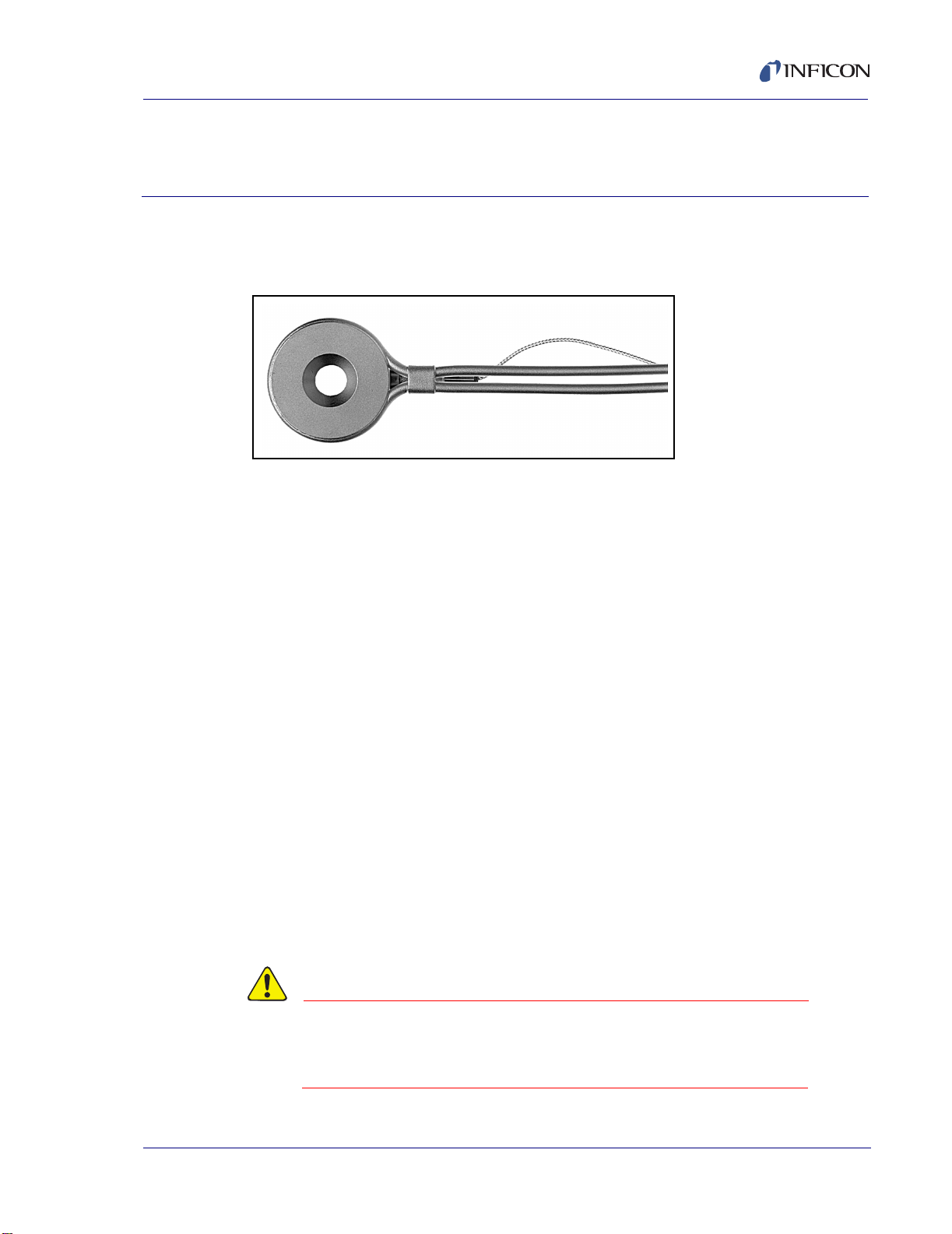
1.1 Specifications for the Sputtering Crystal Sensor
Figure 1-1 Sputtering Crystal Sensor (IPN 750-618-G1)
Maximum bakeout temp
with no water: . . . . . . . . . . . . . . . . . . 105 °C
Size (maximum envelope):. . . . . . . . 1.36" OD x 0.69" high (3.45 cm x 1.75 cm)
Water, air and coax length:. . . . . . . . Standard 30" (76.2 cm)
Crystal exchange:. . . . . . . . . . . . . . . Rear-loading
Sputtering Crystal Sensor Operating Manual
Chapter 1
Sensor Specifications
Mounting: . . . . . . . . . . . . . . . . . . . . . Customer supplied
1.1.1 Installation Requirements
Feedthrough . . . . . . . . . . . . . . . . . . . 2 pass water with coax connector
2-3/4" ConFlat® Flange - IPN 002-043
1" Bolt - IPN 002-42
Other . . . . . . . . . . . . . . . . . . . . . . . . 1. Customer to provide vacuum-tight braze
joints or connectors for the water tubes.
2. XIU or Oscillator designed to interface with
the specific deposition controller.
IPN 074-157L
Water Flow Rate. . . . . . . . . . . . . . . . Minimum water flow 750 cc/min, 30 °C max
Coolant should not contain chlorides as
stress corrosion cracking may occur. If the
water tube passes through a cryoshroud,
drain the tubes if the water flow is stopped for
any reason.
CAUTION
Do not allow water tubes to freeze. This may happen if the
tubes pass through a cryogenic shroud and the fluid’s
flow is interrupted.
1 - 1
Page 14

1.1.2 Materials
Body and Holder . . . . . . . . . . . . . . . Au plated Be-Cu
Springs, Electrical Contacts . . . . . . . Au plated Be-Cu
Water tubes . . . . . . . . . . . . . . . . . . . Au plated Be-Cu,
Connector. . . . . . . . . . . . . . . . . . . . . 304 Stainless steel
Sputtering Crystal Sensor Operating Manual
0.125" (0.32 cm) O.D.
Insulators . . . . . . . . . . . . . . . . . . . . . 99% Al
Wire . . . . . . . . . . . . . . . . . . . . . . . . . Teflon insulated copper
Solder. . . . . . . . . . . . . . . . . . . . . . . . Cadmium free silver and
Crystal . . . . . . . . . . . . . . . . . . . . . . . 0.550" (1.4 cm) Diameter
Magnet . . . . . . . . . . . . . . . . . . . . . . . ALNICO 5 Alloy
1.1.3 Unpacking Instructions
The sensor and accessories are packaged in a single cardboard carton with rigid
foam inserts.
Carefully remove the packaged accessories before removing the
plastic sensor box.
1.1.4 Inventory
In addition to the basic transducer, the complete shipping package
includes the following:
Table 1-1 Shipping Package Contents
2O3
indium alloys
1 - 2
Qty IPN Description
1 074-5000-G1 Thin Film Manuals CD
1 008-009-G10 Assembly, Sputtering Crystal 6MHz
1 750-037-G1 *Spring Tube Bender Kit
1 008-007 Crystal Snatcher
1 750-191-G1 *Molybdenumdisulfide in Alcohol
*Provided with Pneumatic Shutter Module
IPN 074-157L
Page 15
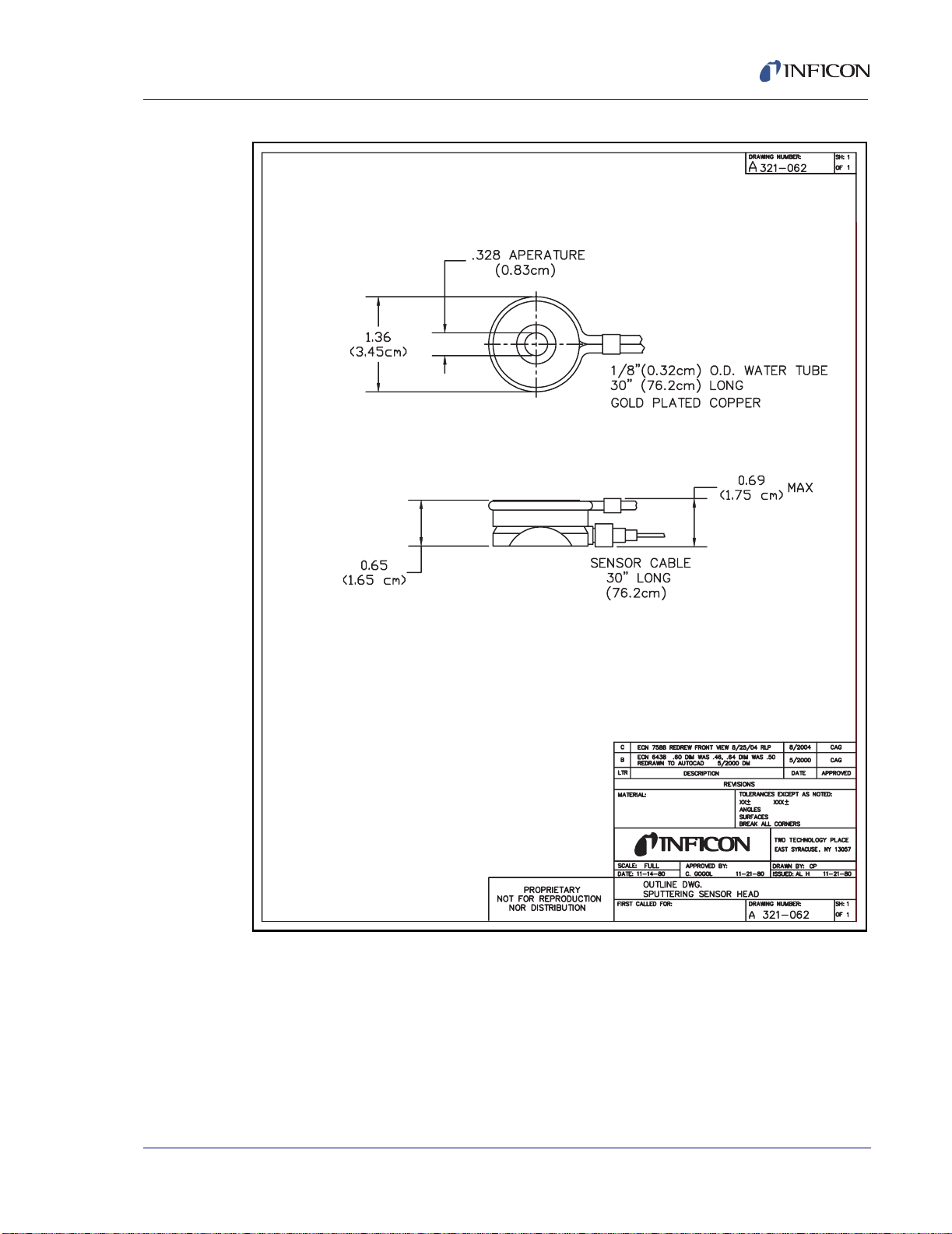
Sputtering Crystal Sensor Operating Manual
Figure 1-2 Sputtering Crystal Sensor Head
IPN 074-157L
1 - 3
Page 16
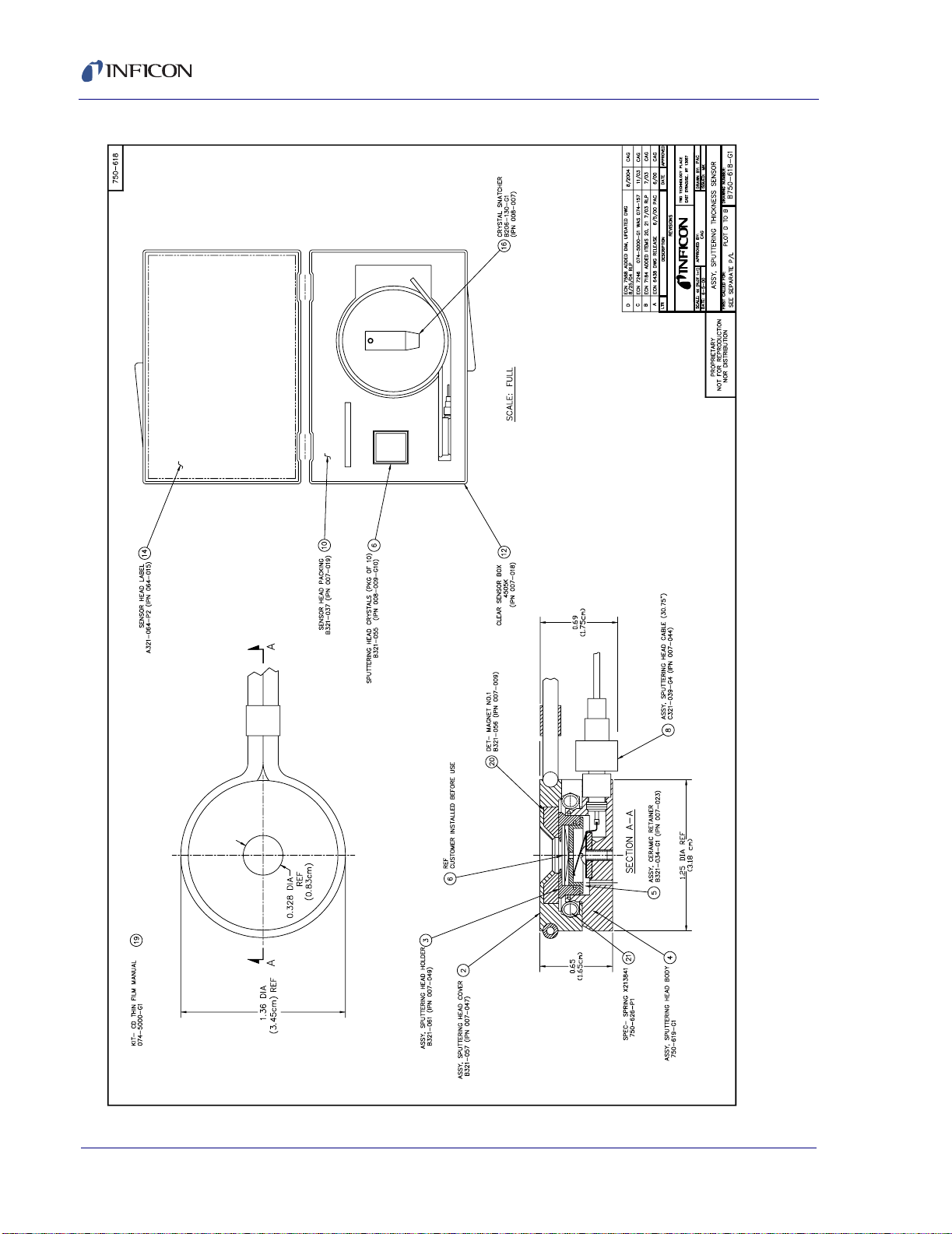
Sputtering Crystal Sensor Operating Manual
1 - 4
Figure 1-3 Sputtering Crystal Head Assembly
IPN 074-157L
Page 17

1.2 Troubleshooting
The most useful tool for diagnosing sensor head problems is the DVM (Digital Volt
Meter). Disconnect the short oscillator cable from the feedthrough and measure the
resistance from the center pin to ground. If the reading is less than 1-2 megohms
the source of the leakage should be found and corrected. Likewise, with the
vacuum system open, check for center conductor continuity, a reading of more than
1
Ω from the feedthrough to the transducer contact indicates a problem. Cleaning
contacts or replacing the in-vacuum cable may be required.
Another useful diagnostic is to continuity-test the sensor head without a crystal.
Install the ceramic retainer (item 5) into the Sputtering Head (item 3) holder without
a crystal (item 6) and place into the Sputtering Head body (refer to Figure 1-3 on
page 1-4). The DVM will measure 1
to ground. Replacing the in-vacuum cable may be required
Table 1-2 Symptom - Cause - Remedy Chart
SYMPTOM CAUSE REMEDY
Sputtering Crystal Sensor Operating Manual
Ω or less from the center pin of the feedthrough
Large jumps of thickness
reading during deposition.
IPN 074-157L
Mode hopping due to
damaged crystal.
Crystal is near the end of its
life.
Scratches or foreign particles
on the crystal holder seating
surface.
Improper crystal seating. Check and clean the crystal
Small pieces of material fell
on the crystal (for crystal
facing-up situation).
Small pieces of magnetic
material being attracted by
the sensor magnet and
contacting the crystal.
Replace the crystal.
Use ModeLock
measurement system.
Replace the crystal.
Clean or polish the crystal
seating surface on the crystal
holder.
seating surface.
Check the crystal surface
and blow it off with clean air.
Check the sensor opening
hole and remove any foreign
material.
1 - 5
Page 18

Sputtering Crystal Sensor Operating Manual
Table 1-2 Symptom - Cause - Remedy Chart (continued)
SYMPTOM CAUSE REMEDY
Crystal ceases to oscillate
during deposition before it
reaches its “normal” life
Crystal is being hit by small
droplets of molten material
from the evaporation source.
Use a shutter to shield the
sensor during initial period of
evaporation; move the
sensor further away.
Damaged crystal. Replace the crystal.
Built-up material on edge of
crystal holder is touching the
crystal.
The crystal cover can not
have a build up of blown in
deposition material. This
material may create an
unreliable connection to the
crystal. Removal of the
deposition material is a
maintenance necessity.
Material on crystal holder is
Clean the crystal holder.
partially masking the full
crystal area.
NOTE: Crystal life is highly dependent on process conditions of rate,
power radiated from source, location, material, and
residual gas composition.
Crystal does not oscillate or
oscillates intermittently (both
in vacuum and in air).
Damaged crystal. Replace the crystal.
Existence of electrical short
or poor electrical contacts.
Check for electrical continuity
and short in sensor cable,
connector, contact springs,
and the connecting wire
inside the sensor; check for
electrical continuity in
feedthroughs.
1 - 6
NOTE: Spring conditions are observed as part of a routine maintenance. Insufficient
bends or deformities in the spring contacts in the sensor body are common
“crystal problems". Lift each spring up approximately 60°.
Crystal oscillates in vacuum
but stops oscillation after
open to air.
Crystal was near the end of
its life; opening to air causes
film oxidation, which
Replace the crystal.
increases film stress.
Excessive moisture
accumulation on the crystal.
Turn off cooling water to
sensor before opening it to
air; flow hot water through
the sensor when the
chamber is open.
IPN 074-157L
Page 19

Sputtering Crystal Sensor Operating Manual
Table 1-2 Symptom - Cause - Remedy Chart (continued)
SYMPTOM CAUSE REMEDY
Thermal instability: large
changes in thickness reading
during source warm-up
(usually causes thickness
reading to decrease) and
after the termination of
deposition (usually causes
thickness reading to
increase).
Poor thickness
reproducibility
Large drift of thickness
reading (greater than 200Å
for density reading = 5.00
gm/cc) after termination of
sputtering.
Crystal not properly seated. Check and clean the crystal
seating surface of the crystal
holder.
Excessive heat input to the
crystal.
If heat is due to radiation
from the evaporation source,
move sensor further away
from source.
No cooling water. Check cooling water flow rate
(refer to see page 1-1).
RF interference from the
sputtering power supply.
Check groundings; change
location of instrument and
oscillator; connect
instrument to different power
line.
Material does not adhere to
the crystal.
Check the cleanliness of the
crystal surface; evaporate an
intermediate layer of proper
material on the crystal to
improve adhesion.
Crystal heating due to poor
thermal contact.
External magnetic field
interferes with the sensor
magnetic field.
Check and clean the crystal
seating surface.
Rotate the sensor magnet to
a proper orientation with
respect to the external
magnetic field.
Sensor magnet defective
(cracked or demagnetized)
Check sensor magnet field
strength; if a gaussmeter is
available, the maximum field
IPN 074-157L
at the center of the opening
hold should give a reading of
700 gauss or greater.
1 - 7
Page 20

Sputtering Crystal Sensor Operating Manual
1.3 Specifications for the Shutter Assembly
Figure 1-4 Pneumatic Shutter Module (750-005-G1) with Sputtering Sensor
1 - 8
Temperature: . . . . . . . . . . . . . . . . . . 130 °C
Materials: . . . . . . . . . . . . . . . . . . . . . 300 series stainless steel
Pressure: . . . . . . . . . . . . . . . . . . . . . 90-95 PSIG (6.2-6.55 bar) [620-655 kPa]
operation 110 PSIG (7.6 bar) [760 kPa]
maximum
Shutter:. . . . . . . . . . . . . . . . . . . . . . . Pneumatically operated
Braze:. . . . . . . . . . . . . . . . . . . . . . . . Vacuum process high temperature
Ni-Cr Alloy
IPN 074-157L
Page 21

Sputtering Crystal Sensor Operating Manual
Figure 1-5 Sputtering Crystal Head w/Pneumatic Shutter
IPN 074-157L
1 - 9
Page 22

Sputtering Crystal Sensor Operating Manual
1 - 10
Figure 1-6 Pneumatic Shutter Module for Sputtering Unit Assembly
IPN 074-157L
Page 23

2.1 Introduction
A choice of sensor type must be determined by the type of process to be
performed, the type of material to be evaporated, and the physical characteristics
of the process chamber.
CAUTION
Sputtering Crystal Sensor Operating Manual
Chapter 2
Sensor Installation
The sensor head, water tubes, cable, etc., should be
clean and grease free when installed in the vacuum
chamber. These parts should be handled while wearing
clean nylon gloves. If parts do become contaminated,
clean them thoroughly using a suitable solvent to avoid
outgassing.
2.2 Pre-installation Sensor Check
Prior to installing the sensor in the vacuum system, you should make certain that it
is in proper working condition by following the appropriate procedure.
2.2.1 IC/5 Deposition Controller
1 Connect the in-vacuum sensor head cable to the feedthrough or a coax adapter
(microdot/BNC).
2 Connect one end of the 6" XIU cable (IPN 755-257-G6) to the BNC connector
IPN 074-157L
or the feedthrough.
3 Connect the other end of the 6" XIU cable to the connector of the XIU/5 (IPN
760-600-G1).
4 Connect one end of the XIU/5 cable (IPN 600-1039-Gxx) to the mating
connector of the XIU/5.
5 Connect the other end of the XIU/5 cable to a sensor channel at the rear of the
controller.
6 Install the crystal as instructed by section 4.2 on page 4-3.
7 Connect power to the controller and set the power switch to ON. Set density at
1.00 gm/cc, and zero thickness. The display should indicate
0 or +/-.001 KÅ. Crystal life should read from 0 to 5%.
2 - 1
Page 24

Sputtering Crystal Sensor Operating Manual
8 Breathe heavily on the crystal. A thickness indication of 1.000 to 2.000 KÅ
should appear on the display. When the moisture evaporates, the thickness
indication should return to approximately zero.
If the above conditions are observed, you can assume the sensor is in proper
working order and may be installed.
2.2.2 Applies to Sensor Installation with an IC-6000 or XTC Deposition Controller
1 Connect the in-vacuum sensor head cable to the feedthrough or coax adapter
(Microdot/BNC).
2 Connect one end of the 6" OSC cable (IPN 013-070) to the receptacle on the
feedthrough.
3 Connect the other end of the 6" OSC cable to the receptacle marked XTAL on
the oscillator (IPN 013-001).
4 Connect the end of the oscillator source/sensor cable (IPN 013-067) to the
remaining BNC receptacle on the oscillator.
5 Connect the other end of the OSC source/sensor cable to the receptacle
marked OSC on the rear panel of the controller.
6 Install the crystal as instructed by section 4.2 on page 4-3.
7 Connect power to the controller and set the power switch to ON. Set density at
1.00 gm/cc and zero the thickness. The display should indicate 0 or ±0.001KÅ.
Crystal life should read from 0 to 4%.
8 Breathe heavily on the crystal. A thickness indication of 1.000 to 2.000 KÅ
should appear on the display. When the moisture evaporates, the thickness
indication should return to approximately zero.
If the above conditions are observed, you can assume the sensor is in proper
working order and may be installed.
2.2.3 Applies to Sensor Installation with an IC/4 or IC/4 PLUS Deposition Controller
1 Connect the in-vacuum sensor head cable to the feedthrough or a coax adapter
(microdot/BNC).
2 Connect one end of the 6" XIU cable (IPN 755-257-G6) to the BNC connector
or the feedthrough.
IPN 074-157L
2 - 2
3 Connect the other end of the 6" XIU cable to the connector of the XIU (IPN
755-252-G1).
4 Connect one end of the 15’ long XIU cable (IPN 755-258-G15) to the mating
connector of the XIU.
Page 25

Sputtering Crystal Sensor Operating Manual
5 Connect the other end of the XIU cable to a sensor channel at the rear of the
controller.
6 Install the crystal as instructed by section 4.2 on page 4-3.
7 Connect power to the controller and set the power switch to ON. Set density at
1.00 gm/cc, and zero thickness. The display should indicate 0 or ±001. Crystal
life should read from 0 to 3%.
8 Breathe heavily on the crystal. A thickness indication of 1.000 to 2.000 KÅ
should appear on the display. When the moisture evaporates, the thickness
indication should return to approximately zero.
If the above conditions are observed, you can assume the sensor is in proper
working order and may be installed.
2.2.4 Applies to Sensor Installation with an
XTC/2 or XTC/C Deposition Controller, or
XTM/2 Deposition Controller
1 Connect the in-vacuum sensor head cable to the feedthrough or a coax adapter
(microdot/BNC)
2 Connect one end of the 6" XIU cable (IPN 755-257-G6) to the BNC connector
or the feedthrough.
3 Connect the other end of the 6" XIU cable to the connector of the XIU (IPN
575-302-G1).
4 Connect one end of the “XX” long XIU cable (IPN 757-303-GXX) to the mating
connector of the XIU.
5 Connect the other end of the XIU cable to a sensor channel at the rear of the
controller.
6 Install the crystal as instructed by section 4.2 on page 4-3.
7 Connect power to the controller and set power switch to ON. Set density at 1.00
IPN 074-157L
gm/cc, and zero thickness. The display indicate 0 or ±.001. Crystal life should
read from 0 to 4%.
8 Breathe heavily on the crystal. A thickness indication of 1.000 to 2.000 KÅ
should appear on the display. When the moisture evaporates, the thickness
indication should return to approximately zero.
If the above conditions are observed, you can assume the sensor is in proper
working order and may be installed.
2 - 3
Page 26

2.3 General Guidelines
Figure 2-1 shows the typical installation of an INFICON® water-cooled crystal
sensor in the vacuum process chamber. Use the illustration and the following
guidelines to install your sensors for optimum performance and convenience.
Figure 2-1 Typical Installation
Sensor
Shutter
Source to Sensor
10" Minimum
Sputtering Crystal Sensor Operating Manual
Mounting Bracket
Coax Cable
(Routed with
Water Tubes)
Brazing
Adapters
Or,
Customer Supplied
Cajon Coupling
Pneumatic
Actuator
Instrument Chassis
Source
Shutter
Source
To
Source Controller
IPN 750-420-G1
Shutter
Solenoid
Assembly
Water In
Water Out
XIU (Oscillator)
Air, 80 PSIG, 110 PSIG Max.
90-95 PSIG for Sputtering Shutter 750-005
To
Sensor
Shutter
IPN 074-157L
2 - 4
Page 27

2.3.1 Crystal Sensor Installation
Generally, install the sensor as far as possible from the evaporation source (a
minimum of 10" or 254 mm) while still being in a position to accumulate thickness
at a rate proportional to accumulation on the substrate. Figure 2-2 shows proper
and improper methods of installing sensors.
Figure 2-2 Sensor Installation Guidelines
Sputtering Crystal Sensor Operating Manual
Correct
Incorrect
Obstruction
Incorrect
Incorrect
Source
Correct
To guard against spattering, use a source shutter to shield the sensor during the
initial soak periods. If the crystal is hit with a minute particle of molten material, it
may be damaged and stop oscillating. Even in cases when it does not completely
stop oscillating, it may immediately become unstable, or shortly after deposition
begins instability may occur.
Plan the installation to insure that there are no obstructions blocking a direct path
IPN 074-157L
between the sensor and the source.
Install sensors in such a manner that the center axis of the crystal is aimed directly
at the source to be monitored. Verify that the angle of the sensor location (with
reference to the source) is well within the evaporant stream.
Assemble the sensor mounting bracket on the process system. With the bracket in
place, temporarily position and attach the sensor head as outlined in the general
guidelines above. Next, temporarily install the feedthrough. You may now form,
measure, and mark the sensor tubes.
Build the Sensor/Feedthrough Assembly. Remove the sensor and the feedthrough,
cut the water cooling tubes and air tubes to the proper length and connect them
directly to the feedthrough or use vacuum rated couplings.
2 - 5
Page 28

Sputtering Crystal Sensor Operating Manual
CAUTION
To prevent damage to the feedthrough or sensor during
brazing, insure that at least one inch of water tube is left
between the sensor and the feedthrough.
After cutting the water and air tubes, verify that they are clear of metal particles by
forcing compressed air through the tubing. Torch brazing is acceptable for
connecting the sensor to the feedthrough water tube.
Vacuum rated connectors, such as CAJON® are recommended for use between
the sensor and the feedthrough to speed maintenance. If brazing adapters are to
be used, attach them to the sensor water-cooling tubes prior to connection to the
feedthrough. Make connections as follows:
1 Clean the water tube and adapter surfaces with solvent if necessary.
2 Apply brazing flux to surfaces being joined.
3 Braze the connections using a flame temperature appropriate for the brazing
material being used.
CAUTION
Excessive application of brazing material, or excessive
heat due to brazing, may result in blockage of the water
tube.
4 Verify that each joint is not blocked by blowing compressed air through the
cooling tubes.
5 Thoroughly clean the braze joint and helium leak test before installing the
sensor and feedthrough into the process chamber.
2.4 Installing the Sputtering Sensor
NOTE: For best process reproducibility, rigidly support the sensor so that it cannot
move during maintenance and crystal replacement.
The sputtering sensor can be installed in any position, and supported by the
water-cooling tube. Cut the water-cooling tube to the proper length and connect it
to the feedthrough with brazing adapters or vacuum couplings. Avoid exposing the
sensor cable to the glow discharge by wrapping the cable around the water-cooling
tube and covering it with aluminum foil. Figure 2-3 shows several possible
locations for the sensor in various sputtering systems.
IPN 074-157L
2 - 6
Page 29

Sputtering Crystal Sensor Operating Manual
Figure 2-3 Suggested Sensor Locations in Sputtering System
Because of geometric factors, variations in surface temperature, and differences in
IPN 074-157L
electrical potential, the crystals and substrates often do not receive the same
amount of material. If you want the thickness indication on the unit to represent the
thickness on the substrates, calibration is required to determine the tooling. Refer
to the instrument manual for calibration procedures. The following precautions
must be observed when installing the sputtering sensor.
1 Use water cooling during the sputtering process. Approximately 0.2 gpm (750
cc/min) at 30 °C maximum temperature water flow should be sufficient for most
applications. Always check the water flow before starting the glow discharge.
2 In sputtering systems which use a substrate shutter, the sensor should be
mounted in a location where it is always exposed to glow discharge. If it is not,
and the shutter is covering the sensor, there will be a small thickness jump
when the shutter is opened, caused by thermal stress in the crystal.
2 - 7
Page 30

Sputtering Crystal Sensor Operating Manual
3 The sensor contains a permanent magnet, see Figure 2-4. If the sensor is to
be installed in a sputtering system which employs external magnetic fields,
make sure the magnetic field direction of the sensor is not opposing the
external magnetic field, see Figure 2-5.
Figure 2-4 Sensor Magnet and Field Configuration
Magnetic
Field Direction
Side
View
Magnetic
Field
Direction
View
From
Inside
Magnet can be rotated
inside the cover.
To secure the magnet, insert a
thin piece of non-ferrous metal
wire or sheet into the gap between
the circumference of the magnet
and its opposing wall.
IPN 074-157L
2 - 8
Page 31

Sputtering Crystal Sensor Operating Manual
Figure 2-5 Orientation of Sensor Magnetic Field in a Sputtering System
Employing External Magnetic Field
The cancellation of magnetic fields near the sensing crystal may cause
undesirable heating of the crystal. Use a small magnet to determine the field
IPN 074-157L
direction and rotate the magnet in the sensor to a desirable position. The
sensor magnet can be held in position by inserting a small piece of thin
non-magnetic wire or sheet into the gap between the circumference of the
magnet and the opposing wall. The sensor’s magnetic field is localized, and will
not affect the external magnetic field to any extent.
4 The sensor is always at ground potential and cannot be made floating. In
sputtering systems where the substrate holder (anode) is biased, the sensor
should be located where it is electrically isolated from the substrate holder and
where it does not affect the electric field near substrates.
5 Be sure both the sensor and the vacuum system are adequately grounded.
2 - 9
Page 32

2.5 Sensor Shutter Function Check
Temporarily connect an air supply — (90-95 PSIG (6.2-6.55 bar) [620-655 kPa];
110 PSIG (7.6 bar) [760 kPa] maximum) — to the actuator air line and test
operation (10-15 cycles). When actuated, shutter movement should be smooth,
rapid, and complete, and should contract completely from the crystal opening.
When deactivated, the shutter should completely cover the crystal opening. If
operation is impaired, lubricate the moving parts, in areas specified on Figure 1-6
on page 1-10, with molybdenumdisulfide or its equivalent. If the function check
was successful, make appropriate pneumatic, water, and coax cable connections
using a suitable feedthrough assembly. Consult section 4.5 on page 4-5 for
information regarding maintenance of the sensor shutter.
WARNING
Do not exceed the maximum pressure rating of 110 PSIG
(7.6 bar) [760 kPa]. Connection to excessive pressure
may result in personal injury or equipment damage.
Sputtering Crystal Sensor Operating Manual
2 - 10
IPN 074-157L
Page 33

Sputtering Crystal Sensor Operating Manual
2.6 Sputtering Sensor Shutter Module
Installation Instructions
2.6.1 Introduction
The Sputtering Shutter Module installation kit was designed to facilitate the
mounting of a pneumatic shutter module onto a sputtering sensor. The pneumatic
shutter module is assembled and tested prior to shipment.
To install the pneumatic shutter module, you must have the parts shown
in Table 2-1.
Table 2-1 Parts Required to Install the Pneumatic Shutter Module
Qty. Description IPN
1 Pneumatic Shutter Assembly 750-005-G1 (refer to section 1.3 on
1 Sputtering Sensor Assembly 750-618-G1 (refer to Chapter 1)
NOTE: The following parts are listed as suggested equipment and may be
ordered separately.
page 1-8)
1 1” Crystal Feedthrough with Airline
(or equivalent)
OR
1 2-3/4” Dual Coaxial Instrumentation
Feedthrough Copper Gasket with
Airline
1 Solenoid Valve Assembly 750-420-G1 (see Chapter 3)
IPN 074-157L
750-030-G1 (see Figure 5-2 on
page 5-3)
002-080-G1 (see Figure 5-4 on
page 5-5)
2 - 11
Page 34

2.6.2 Installation
Before you begin the installation, refer to the illustrations to get an idea of how the
parts are assembled. The shutter assembly may be installed onto a new Sputtering
sensor or a used sensor in good condition.
1 Remove the actuator cover screw (4-40 x 3/16) on the shutter assembly and
remove the actuator cover. See Figure 2-6.
Figure 2-6 Top-View
Sensor Cover
Sputtering Crystal Sensor Operating Manual
Actuator Cover
Shutter
Actuator
Mounting
Screws
Actuator Cover Screw
2 Remove two water tube clamp screws (4-40 x 1/4) (not shown) and remove the
clamp. See Figure 2-7.
3 Remove the sensor body assembly from the sensor cover and set it in a clean
safe place. This is to protect the head during the installation. See Figure 2-7.
Figure 2-7 Side View
Sensor Cover
Water Tube
Clamp
Sensor Body
Assembly
Cable
IPN 074-157L
2 - 12
Page 35

Sputtering Crystal Sensor Operating Manual
Figure 2-8 Bottom View
Stop Screw
Shutter Pivot
Actuator
Mounting Bracket
Water Tube ClampStop Screw
4 Place the sensor cover on the shutter module assembly as shown in Figure
2-8. The sensor water lines will fit between the shutter pivot and the stop screw.
Carefully bend the water lines as shown.
5 Position the water line clamp on the shutter assembly and install the two
mounting screws. Tighten the screws finger tight.
6 Position the sensor cover as shown in Figure 2-6. The shutter should cover the
sensor cover as shown. It may be necessary to align the sensor slightly to
achieve correct positioning.
7 The plane of the shutter and sensor cover should be parallel as shown in
Figure 2-7. Again, it may be necessary to align the sensor slightly to achieve
correct positioning.
8 Tighten the two water tube clamp screws.
9 Manually rotate the shutter away from the sensor cover as shown in Figure 2-6
and then let it go; the return operation should be smooth and unobstructed.
10 Install the actuator cover on the shutter actuator assembly and install the
actuator cover screw (4-40 x 3/16). (Refer to Figure 2-6.)
11 Install the sensor body assembly into the sensor cover. The assembly will now
appear as shown in Figure 2-7.
IPN 074-157L
2 - 13
Page 36

Sputtering Crystal Sensor Operating Manual
This page is intentionally blank.
2 - 14
IPN 074-157L
Page 37

Installation of the Solenoid Valve Assembly
3.1 Introduction
The solenoid valve assembly and the feedthrough should be installed at the same
time. The same valve assembly is used for both the 1" and the (recommended) 2
3/4" feedthroughs. However, if the assembly is to be used with the 2 3/4"
feedthrough, you will need to modify the valve bracket as follows. See Figure 5-6
on page 5-7.
1 Align the score line on the valve assembly bracket over the edge of a table or
other square edge.
2 Using pliers, grasp the part of the bracket extending over the edge and push
down. The assembly will break along the score line. Use a file to smooth any
rough edges which occur along the break.
Sputtering Crystal Sensor Operating Manual
Chapter 3
3.2 Installation with 1" Bolts
If you are installing the solenoid valve assembly for utilization with a dual sensor,
you will need two 1" bolts. (IPN 002-042 — see Figure 5-1 on page 5-2.) Use the
first as is; on the second, one water tube must be plugged, the other must have a
fitting adapter (IPN 007-133) soldered to it. (This part is only available from
INFICON.)
If you are installing the solenoid valve assembly for utilization with any other
sensor, you will need only one 1" bolt feedthrough (IPN 750-030-G1, see Figure
5-2 on page 5-3.)
Follow the steps below:
1 Ensure that the o-ring is in place on the bolt. Insert the 1" bolt such that the
IPN 074-157L
hexagonal shaped end of the bolt is on the vacuum side of the chamber.
2 Add the Bracket.
3 Add the Washer.
4 Add the Nut.
5 Tighten the feedthrough nut.
6 Install the air fitting to the tube which has the female thread adapter installed.
7 Connect the 1/8" air tube from the valve to the just installed fitting.
3 - 1
Page 38

Sputtering Crystal Sensor Operating Manual
CAUTION
Applicable to sensor 750-446 only: Use of more than 80"
(2 meters) of 1/8" tubing between the valve and the
bellows may cause switcher failure because of the time
required to bleed out sufficient air during
de-pressurization. If tubing greater than 1/8" is used, the
maximum length must be reduced proportional to the
additional volume.
8 Attach the valve’s intake (normally closed (NC) port) to the 80-90 PSIG (5.5-6.2
bar) [550-620 kPa] source of air. Or, 90-95 PSIG (6.2-6.55 bar) [620-655 kPa]
air supply for the Sputtering Shutter (IPN 750-005).
3.3 Installation with 2 3/4" Feedthrough
If you are installing the solenoid valve assembly with a dual sensor, a
2 3/4" feedthrough inclusive of two coaxial feedthroughs (IPN 002-080, see Figure
5-4 on page 5-5) is required. All other shuttered sensors utilizing 2 3/4"
feedthroughs require only a single coaxial feedthrough. The second coaxial
feedthrough is not used, and should be protected from damage as a result of
process material. Follow the steps below:
1 Install the Feedthrough.
2 Add the valve bracket (modified) to the desired location utilizing two of the
flange’s 1/4" clamp bolts.
3 Tighten the flange bolts.
4 Install the air fitting to the female thread adapter.
5 Connect the 1/8" air tube from the valve outlet to the feedthrough fitting. See
the caution at the top of this page.
6 Attach the valve’s intake (normally closed (NC) port) to the 80-90 PSIG (5.5-6.2
bar) [550-620 kPa] source of air. Or, 90-95 PSIG (6.2-6.55 bar) [620-655 kPa]
air supply for the Sputtering Shutter (IPN 750-005).
NOTE: Maximum temperature for the shutter control valve assembly is 105 °C for
bakeout and operation.
IPN 074-157L
3 - 2
Page 39

Sputtering Crystal Sensor Operating Manual
3.4 Electrical and Pneumatic Connections
3.4.1 Electrical
To complete installation of the assembly, make electrical connections where
indicated in Figure 5-5 on page 5-6 to either 24 V(ac) or V(dc). Current required
is approximately 70 mA.
CAUTION
Maximum applied voltage must not exceed 26 V(ac).
3.4.2 Pneumatic
Figure 3-1 Pneumatic Solenoid Tube Connections
Figure 3-1a
Solenoid Valve
Without Orifice
(As Supplied)
P SUPPLY
(Normally Closed)
80-90 PSIG
AIR SUPPLY
90-95 PSIG for the
Sputtering Shutter
IPN 750-005
TUBE FITTING
(Provided with Valve)
Figure 3-1b
Solenoid Valve
With Orifice
(Installed by User)
IPN 074-157L
Figure 3-1b shows the proper installation for
all CrystalSix applications.
EXHAUST
(Normally Open)
A OUTPUT
PORT
TO AIR
FITTING OF
FEEDTHROUGH
EXHAUST
(Normally Open)
80-90 PSIG
AIR SUPPLY
P SUPPLY
(Normally Closed)
TUBE FITTING
(Provided with Valve)
A OUTPUT
PORT
TO AIR
FITTING OF
FEEDTHROUGH
ORIFICE (059-189)
(Provided with Accessory Kit 750-268-G1)
3 - 3
Page 40

Sputtering Crystal Sensor Operating Manual
This page is intentionally blank.
3 - 4
IPN 074-157L
Page 41

4.1 General Precautions
4.1.1 Handle the Crystal with Care
Always use clean nylon lab gloves and clean plastic tweezers when handling the
crystal. Handle the crystals only by their edges. Anything that comes in contact with
the crystal surfaces may leave contamination, which may lead to poor film
adhesion. Poor film adhesion will result in high rate noise and premature crystal
failure.
CAUTION
Do not use metal tweezers to handle crystals. Metal
tweezers may chip the edge of the crystal.
Sputtering Crystal Sensor Operating Manual
Chapter 4
Maintenance
4.1.2 Maintain the Temperature of the Crystal
Periodically measure the water flow rate through the crystal sensor to verify that it
meets or exceeds the value specified on see page 1-1. Depending upon the
condition of the cooling water used, the addition of an in-line water filtering
cartridge system may be necessary to prevent flow obstructions. Many system
coaters use parallel water supply taps that provide high total flows. An obstruction
or closed valve in the pipe that supplies water to the sensor head would not result
in a noticeable reduction of total flow. The best test is to directly monitor the flow
leaving the sensor.
The crystal requires sufficient water cooling to sustain proper operational and
IPN 074-157L
temperature stability. Ideally, a constant heat load is balanced by a constant flow of
water at a constant temperature. INFICON’s quartz crystals are designed to
provide the best possible stability under normal operating conditions. No crystal
can completely eliminate the effects of varying heat loads. Sources of heat
variation include radiated energy emanating from the evaporant source and from
substrate heaters.
4.1.3 Use the Optimum Crystal Type
Silver crystals are recommended for sputtering applications. Certain materials,
especially dielectrics, may not adhere strongly to the crystal surface and may
cause erratic readings. For many dielectrics, adhesion is improved by using
crystals with silver coated electrodes. Gold is preferred for other applications.
4 - 1
Page 42

Sputtering Crystal Sensor Operating Manual
4.1.4 Crystal Concerns when Opening the Chamber
Thick deposits of some materials, such as SiO, Si and Ni will normally peel off the
crystal when it is exposed to air, due to changes in film stress caused by gas
absorption. When peeling material is observed, replace the crystal.
4.1.5 Care of the Ceramic Retainer
CAUTION
Do not use excessive force when handling the Ceramic
Retainer Assembly since breakage may occur. Always
use the crystal snatcher.
To prevent scratching the crystal electrode, do not rotate
the ceramic retainer after installation.
Always use clean nylon lab gloves and plastic tweezers
for handling the crystal. This avoids contamination which
may lead to poor adhesion of deposited material to the
electrode.
4.1.6 Leaf Spring Concerns
Spring conditions should be observed as part of the routine maintenance interval.
Insufficient bends or deformities in the spring contacts in the sensor body are
common causes of crystal problems. Lift each leaf spring up approximately 60°.
Figure 4-1 Shaping the Leaf Spring
Avoid kinking
leaf spring
IPN 074-157L
Leaf
Spring
60°
4 - 2
Page 43

Sputtering Crystal Sensor Operating Manual
4.2 Crystal Replacement Instructions
Follow the steps below to replace the crystals: (Refer to Figure 1-3 on page 1-4).
Observe the general precautions (refer to section 4.1 on page 4-1) for replacing
crystals.
1 Grip the crystal holder with your fingers and pull it straight out to separate it from
the water-cooled front part. (You may have to disconnect the sensor cable in
order to separate the parts.)
2 Pull the crystal holder straight out from the front of the sensor.
3 Insert the tapered end of the crystal snatcher (part number 008-007) into the
ceramic retainer (Figure 4-2-A) and apply a small amount of pressure. This
locks the retainer to the snatcher and allows the retainer to be pulled straight
out (Figure 4-2-B).
Figure 4-2 Using the Crystal Snatcher
4 Invert the crystal holder and the crystal will drop out.
5 Prior to installing the new crystal, review section 4.1.1, Handle the Crystal
with Care, on page 4-1.
6 Using clean nylon gloves, grasp the edge of the new crystal with a clean pair of
plastic tweezers. Orient the crystal so the patterned electrode is facing up.
IPN 074-157L
Gently insert the edge of the crystal beneath one of the wire segments that
protrude into the crystal cavity. Release the crystal.
7 Replace the ceramic retainer. Initially orient it at an angle to displace the spring
wire segments in the crystal holder.
8 Release the crystal snatcher with a slight side-to-side rocking motion. Using the
backside of the crystal snatcher, push on the ceramic retainer to ensure it is
completely seated.
9 Put the holder into the front cover of the sensor.
10 Align the position of the back part so that the connector matches with the notch
on the front of the sensor. Snap the two parts together. Reconnect the sensor
cable if it has been disconnected.
4 - 3
Page 44

Sputtering Crystal Sensor Operating Manual
4.3 Retainer Spring Adjustment Instructions
Occasionally, you may become dissatisfied with the way the ceramic retainer is
secured in the crystal holder. To alter the magnitude of the retaining force, use the
following procedure.
Tools Required
Scribe or other pointed tool
Needle nose pliers (two required)
Procedure
1 Position the crystal holder with the crystal aperture oriented downward.
2 Insert the point of the scribe between the inside edge of the crystal holder cavity
and one of the two wire segments that protrude into the crystal cavity (Figure
4-3-a).
Figure 4-3 Location of the Transition Point
Wire
Scribe
Crystal Holder
Move location of transition point in this
direction to decrease retainer retention force.
Move location of transition point in this
direction to increase retainer retention force.
Location of Transition Point
3 Using the scribe, gently remove the spring from its groove in the crystal holder
cavity.
4 Consult Figure 4-3-b to determine the direction in which the ‘transition point’
must be relocated, to attain the desired retention forces. Moving this transition
point approximately 1/16" is generally sufficient.
IPN 074-157L
4 - 4
5 Grasp the spring, with the pliers, just below the transition point. Using the
second set of pliers, bend the spring as illustrated by the dashed line in Figure
4-3-c to remove the existing transition point.
Page 45

Sputtering Crystal Sensor Operating Manual
6 Use both pliers to form a new transition point according to Figure 4-3-b, thus
returning the spring to a shape similar to the solid line delineation of
Figure 4-3-c.
7 Reinstall the spring into the groove provided in the crystal cavity.
8 Determine if the retention force is acceptable and that the wire does not impede
crystal insertion. Repeat these instructions if unacceptable retention forces
persist.
4.4 Crystal Holder Maintenance
In dielectric coating applications, the surface where the crystal contacts the crystal
holder may require periodic cleaning. Since most dielectrics are insulators, any
build-up due to blow-by will eventually cause erratic or poor electrical contact
between the crystal and the sensor body. This build-up will also cause a reduction
in thermal transfer from the crystal to the sensor body. Both of these will result in
noisy operation and early crystal failure.
Cleaning may be accomplished by gently buffing the crystal holder to crystal
seating surface with a white Scotch-Brite™ pad followed by an ultrasonic bath in
soap solution followed by thorough rinsing in deionized water and drying or by
ultrasonic cleaning and rinsing only.
NOTE: The crystal holder seating surface is machined to a very fine finish (16
micro inches rms). This high quality finish is essential to provide good
electrical and thermal contact with the crystal. Applying excessive force
during cleaning or using overly abrasive cleaning materials may damage
this finish and reduce sensor performance.
4.5 Sputtering Sensor Shutter Maintenance
The sensor shutter should be dismantled approximately every 2000 strokes for
lubrication with molybdenum disulfide in alcohol (IPN 750-191-G1) or equivalent in
IPN 074-157L
the areas specified on Figure 1-6 on page 1-10. Failure to lubricate may
significantly reduce life of operation or cause the assembly to become totally
inoperative.
4 - 5
Page 46

Sputtering Crystal Sensor Operating Manual
This page is intentionally blank.
4 - 6
IPN 074-157L
Page 47

Feedthrough Outline Drawings
5.1 List of Supplied Drawings
The following Feedthrough Outline Drawings provide dimensions and other
pertinent data necessary for planning equipment configurations.
Figure 5-1 . . . . . . . . . . . . . . . . . . . . 1" Crystal Feedthrough (002-042) (contains
Figure 5-2 . . . . . . . . . . . . . . . . . . . . 1" Crystal Feedthrough w/Air Tube (IPN
Figure 5-3 . . . . . . . . . . . . . . . . . . . . Standard 2 3/4" ConFlat® (IPN
Sputtering Crystal Sensor Operating Manual
Chapter 5
one coaxial and two water tubes)
750-030-GI) (contains one coaxial, two water
tubes and one air tube).
002-043/002-044) (contains one coaxial and
two water tubes).
002-043 utilizes copper gasket
002-044 utilizes Viton® gasket
Figure 5-4 . . . . . . . . . . . . . . . . . . . . Standard 2 3/4" ConFlat® Flange (002-080)
(contains two coaxials, two water tubes and
one air tube).
Figure 5-5 . . . . . . . . . . . . . . . . . . . . 2 3/4" Dual Coaxial Feedthrough and Valve
Assembly
Figure 5-6 . . . . . . . . . . . . . . . . . . . . Solenoid Valve Assembly
IPN 074-157L
5 - 1
Page 48

Figure 5-1 1" Crystal Feedthrough (002-042)
1" WASHER
MICRODOT CONNECTOR
0.75
Sputtering Crystal Sensor Operating Manual
HEX NUT
BNC CONN.
SEAMLESS TUBE
0.188 O.D., 0.131 I.D.
1.50
0.156
0.2
5.00
0.2
0.4
2.00
5.00
0.75
5 - 2
IPN 074-157L
Page 49

Sputtering Crystal Sensor Operating Manual
Figure 5-2 1" Crystal Feedthrough with Air Tube (750-030-G1)
1" CRYSTAL FEEDTHROUGH W/AIR TUBE
0.75
5.00
MICRODOT CONNECTOR
0.38
0.50
0.25
0.125
13.00
0.188
2.00
BNC CONNECTOR
1
0.28
SEAMLESS TUBE
0.188 O.D., 0.131 I.D.
# 10-32 INTERNAL THREAD
1.00
.
5
0
0.312 HEX
IPN 074-157L
5 - 3
Page 50

Figure 5-3 2 3/4" Single Coaxial Feedthrough
(002-043 - Copper Gasket)
(002-044 - Viton)
Sputtering Crystal Sensor Operating Manual
2-3/4 CONFLAT FLANGE
BNC CONNECTOR
2.75
5.00
0.30
0.5
0.265 DIA. (6)
0.20
CONNECTOR MICRODOT
9.00
0.40
SEAMLESS TUBE (3)
0.188 O.D., 0.131 I.D.
0.60
IPN 074-157L
5 - 4
Page 51

Sputtering Crystal Sensor Operating Manual
Figure 5-4 2 3/4" Dual Coax Feedthrough with Air Tube (002-080)
2-3/4 CONFLAT FLANGE
BNC CONNECTOR
#10/32 INTERNAL THREAD
2.15
0.265 DIA. (6)
0.40
0.20
5.00
0.40
0.45
0.5
0.312 HEXAGONAL
0.45
CONNECTOR MICRODOT
9.00
0.90
2.75
SEAMLESS TUBE (3)
0.188 O.D., 0.131 I.D.
IPN 074-157L
5 - 5
Page 52

Sputtering Crystal Sensor Operating Manual
5 - 6
Figure 5-5 2 3/4" Dual Coaxial Feedthrough and Valve Assembly
IPN 074-157L
Page 53

Sputtering Crystal Sensor Operating Manual
Figure 5-6 Solenoid Valve Assembly
IPN 074-157L
5 - 7
Page 54

Sputtering Crystal Sensor Operating Manual
This page is intentionally blank.
5 - 8
IPN 074-157L
 Loading...